

Page 1
Operating Manual
PMS, HTE and MobiScan Family
with Standard Program Version 6
Page 2
Operating Manual
PMS, HTE and MobiScan Family
with Standard Program Version 6
Page 3

We do not only deliver our mobile Terminals with
Standard Software...
we are also developing custom specific
applications for these devices,
•
PC applications,
•
hardware
•
and consult you concerning
• creation of mobile data capturing concepts,
• questions coming up with barcodes,
• hardware problems,
PC problems.
•
Please contact:
aitronic GmbH
Max-Planck-Str. 19
D-33104 Paderborn
Phone: +49(0)5254/9969-0
Fax: +49(0)5254/9969-40
Internet: http://www.aitronic.de
eMail: [email protected]
__________________________________________________________
Copyright aitronic GmbH, 2004
All rights reserved, especially also excerpts for translation, printing, copying
or similar processes.
Possibility of delivery and technical modification reserved.
Page 4

Contents _________________________________________________________________
1
1. Introduction .................................................................... 1-1
2. Warning Hints................................................................. 2-1
Laser Scanner Module............................................................................... 2-1
Accus......................................................................................................... 2-1
3. Security & Regulatory.................................................... 3-1
4. Care Instructions............................................................ 4-1
Care of the Scanner .................................................................................. 4-1
Dealing with the Devices Markings............................................................ 4-1
Repairing Screen Damages....................................................................... 4-1
5. Communication/Charging Adapter............................... 5-1
6. Installation of PC Software MTWIN............................... 6-1
7. Introduction to Operation .............................................. 7-1
Switching on/off ......................................................................................... 7-3
LCD Displays............................................................................................. 7-3
Scanner Handling ...................................................................................... 7-4
Manually Data Entry .................................................................................. 7-5
Deleting Characters................................................................................... 7-5
Deleting Entry Field ................................................................................... 7-5
Select next Entry Field............................................................................... 7-6
Closing Entry and storing the Record ........................................................ 7-6
8. System Functions .......................................................... 8-7
8.1 Cold Start / Initialization.......................................................................... 8-7
8.2 Reset Button ............................................................................................ 8-9
Warm Start .............................................................................................. 8-11
Cold Start / Initialization........................................................................... 8-11
Calling the Boot Program......................................................................... 8-11
8.3 Battery Low Procedure ......................................................................... 8-12
8.4 Menu System ......................................................................................... 8-13
Calling/leaving the Menu System............................................................. 8-13
Selecting Menus ...................................................................................... 8-13
Selecting Menu Functions ....................................................................... 8-14
____________________________________________________________________ aitronic
Page 5

_________________________________________________________________ Contents
2
Executing Menu Functions .......................................................................8-14
Returning to Menu System.......................................................................8-14
Menü: 1 APPLICATION............................................................................8-14
Menü: 2 DATA MEMORY.........................................................................8-15
Menü: 3 COMMUNICATION ....................................................................8-15
Sub-Menü: 3 DECT Functions..................................................................8-16
Menü: 4 SETUP .......................................................................................8-17
8.5 Function Barcodes.................................................................................8-18
Commands...............................................................................................8-18
Program Selection....................................................................................8-19
Standard Barcode Menu ..........................................................................8-20
8.6 Charging the integrated Accumulators ................................................8-26
8.7 Error Messages ......................................................................................8-27
8.8 Error Diagnostics ...................................................................................8-31
9. Software Update ............................................................. 9-1
10. Technical Data ......................................................... 10-1
Mobile Terminals PMS 1200/1500 ...........................................................10-1
Mobile Terminals HTE 1800/1900 and MobiScan-6x/8x...........................10-2
Scanner Modules .....................................................................................10-3
11. Accessories ............................................................. 11-1
Protection cap for PMS ............................................................................11-1
Belt Holster for MobiScan 6x....................................................................11-1
Redirection Optic for HTE ........................................................................11-1
RS-232 Cable for HTE and MobiScan......................................................11-2
2-Bay Charging Cradle for HTE 1900.......................................................11-2
Cradle MobiScan 6x PTR.........................................................................11-2
2-Bay Cradle MobiScan 6x/8x UDS..........................................................11-3
1-Bay Cradle UDS with RS-232 and LAN Interface..................................11-3
Cradle 1-fach UDS ...................................................................................11-3
Accesspoint for DECT RF Network ..........................................................11-4
12. Recycling Orders..................................................... 12-1
Battery Order............................................................................................12-1
IT Salvage Devices Order ........................................................................12-1
13. Additional Manuals
A
PPLICATION PROGRAMMING MANUAL
CONNECTIVITY & APPLICATIONS ...................................................................13-1
aitronic
___________________________________________________________________
ECHNICAL MANUAL
..........................................................13-1
..................... 13-1
Page 6

Contents _________________________________________________________________
3
WIND
DECT RF N
.................................................................................................. 13-1
ECT
ETWORK
................................................................................. 13-1
14. Standard Program MTSTD...................................... 14-1
Initialization following Cold Start .............................................................. 14-1
Data Capturing ........................................................................................ 14-2
Displaying Records.................................................................................. 14-3
Modifying/deleting/undeleting a Record................................................... 14-3
Function Keys.......................................................................................... 14-3
Data Transmission................................................................................... 14-4
Erasing the Data Memory........................................................................ 14-6
Test Barcodes ......................................................................................... 14-7
____________________________________________________________________ aitronic
Page 7

__________________________________________________________________________
Before working with your device you should study this manual carefully.
All informations in this manual are given without any guarantee and may be altered
by us without any prejudice. We take care to keep our products errorfree and on the
latest technical level. As possible we try to stay compatible to our delivered
products. Although we take much care in producing and testing our software it is not
possible to guarantee the functionality allways and completely under all thinkable
operating conditions.
Attention
responsible for compliance could void the user's authority to operate the equipment.
: Changes or modifications not expressly approved by the party
For personal or material damage resulting directly or indirectly from the usage of our
devices or software aitronic GmbH cannot take over liability.
This manual or parts of it are not allowed by aitronic GmbH to be copied or mailed in
any way. Copies of the software may only be used for backup purposes but may be
not given to third ones.
Trade-marks and trade-names in this manual which are not specially be marked are
only therefore not free of any rights.
We are willingly to help you with any problems or questions concerning our
products. Please consult:
aitronic GmbH
Max-Planck-Str. 19
D-33104 Paderborn
Phone: +49(0)5254/9969-0
Fax: +49(0)5254/9969-40
Internet: http://www.aitronic.de
eMail: [email protected]
____________________________________________________________________ aitronic
Page 8

Introduction______________________________________________________________
1-1
1. Introduction
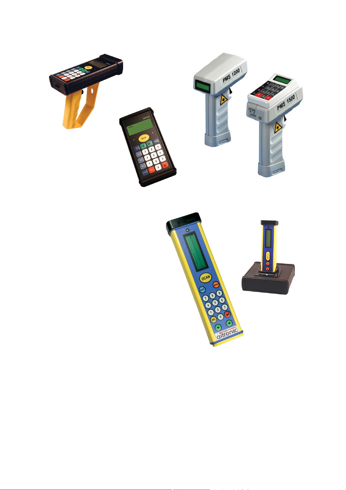
The mobile terminals
are usable in several ways for scanning barcodes and manually data capturing.
Different device types and options are available (refer to
chapter
Depending on the type of the serial interface off- and online network applications
can be implemented.
For all devices in this manual the designation MT (Mobile Terminal) is used.
All
device types are named
of devices without keyboard. In function descriptions which concern only to devices
with keyboards a particular reference is made.
1 Device Types
PMS 1200/1500
PMS 1200/1500, HTE 1800/1900
).
device types in this manual are named
. In general devices with keyboard include all functions
HTE
and
MobiScan
PMS
from aitronic
Technical Manual
, all
HTE 1800/1900
,
____________________________________________________________________ aitronic
Page 9

Warning Hints____________________________________________________________
2-1
2. Warning Hints
Laser Scanner Module
The mobile terminals
diode for visible light. The wave length is 650 nm and the nominal laser power is 1,2
mW. The laser scanner meets the CDRH/IEC Class II requirements.
As with other strong light sources the operator should avoid looking directly into the
laser beam. Occasionally irradiation with CDRH/IEC Class II laser light is not known
to be injurious.
The required security labels are located below the laser light window.
Never open the laser module or perform any maintenance work at the module
because the laser security specification may be injured. The laser module may only
be repaired in the factory.
PMS/HTE/MobiScan
are equipped with a low power laser
Accus
Attention!
explosion. In case of waste disposal of used accus you should pay attention to the
Recycling Orders (look for chapter
At this point we want to explicitly attention
guarantee for damages which are the consequence of wrong dealing with the
devices.
In case of improper handling of the accus there will be danger of
Recycling Orders/Battery Order
to that we don’t overtake
).
____________________________________________________________________ aitronic
Page 10

Security & Regulatory______________________________________________________
3-1
3. Security & Regulatory
This device complies with Part 15 of the FCC Rules. Operation is subject to the
following two conditions:
(1) this device may not cause harmful interference, and
(2) this device must accept any interference received, including interference that
may cause undesired operation.
____________________________________________________________________ aitronic
Page 11

Care Instructions _________________________________________________________
4-1
4. Care Instructions
Your data capturing device with integrated laser scanner module is a high grade
and robust unit consisting of electronic and laser optic devices. An faulty treatment
of this device can considerable affect function and efficiency. To guarantee lasting
and constant operation you should consider the following care instructions!
Care of the Scanner
The red scanner screen of your terminal forms and the inner resided scanner
module form an optical unit. This screen is provided with a special coating. A
damage of this coating i.e. by scratches may lead to problems when scanning
barcodes. Because of this a clean and moist cloth should be used when cleaning
the screen. Before rough dirt may be removed with a soft brush. Cleaning agents
may not be used for the screens care and cleaning.
Terminal of the MobiScan family habe an aluminum case. All other scanners from
ours have a plastic case. Although both are robust materials for cleaning only a soft
cleaning angent should be used.
Dealing with the Devices Markings
The attached marking labels (warning and security labels) may not be removed on
principle. They are the legitimation for the operation with this terminal. Making the
terminals data plate or informations on the data plate (i.e. the serial number)
unrecognizable should be avoided. Missing information on the data plate may lead
to a more difficult identification. This may further lead to problems which couldn’t be
solved by telephone. In this case the terminal must be sent in.
Further we recommend the attachment of additional information (i.e. department or
personal numbers) labels with plastic back. Simple paper back labels aren’t durable
enough. In that way sticking parts may smudge the scanner screen. In this case on
the one hand the scanner function will be affected, on the other hand a cleaning
without ignoring the above instructions woun’t possible because a solvent would be
required.
Repairing Screen Damages
In case of overstress the screen may be loosen. We explicitly attention to that self
repairing with short time glue may affect in such strong way that the screen or the
casing must be changed.
____________________________________________________________________ aitronic
Page 12
Communication/Charging Adapter ____________________________________________
5-1
5. Communication/Charging Adapter
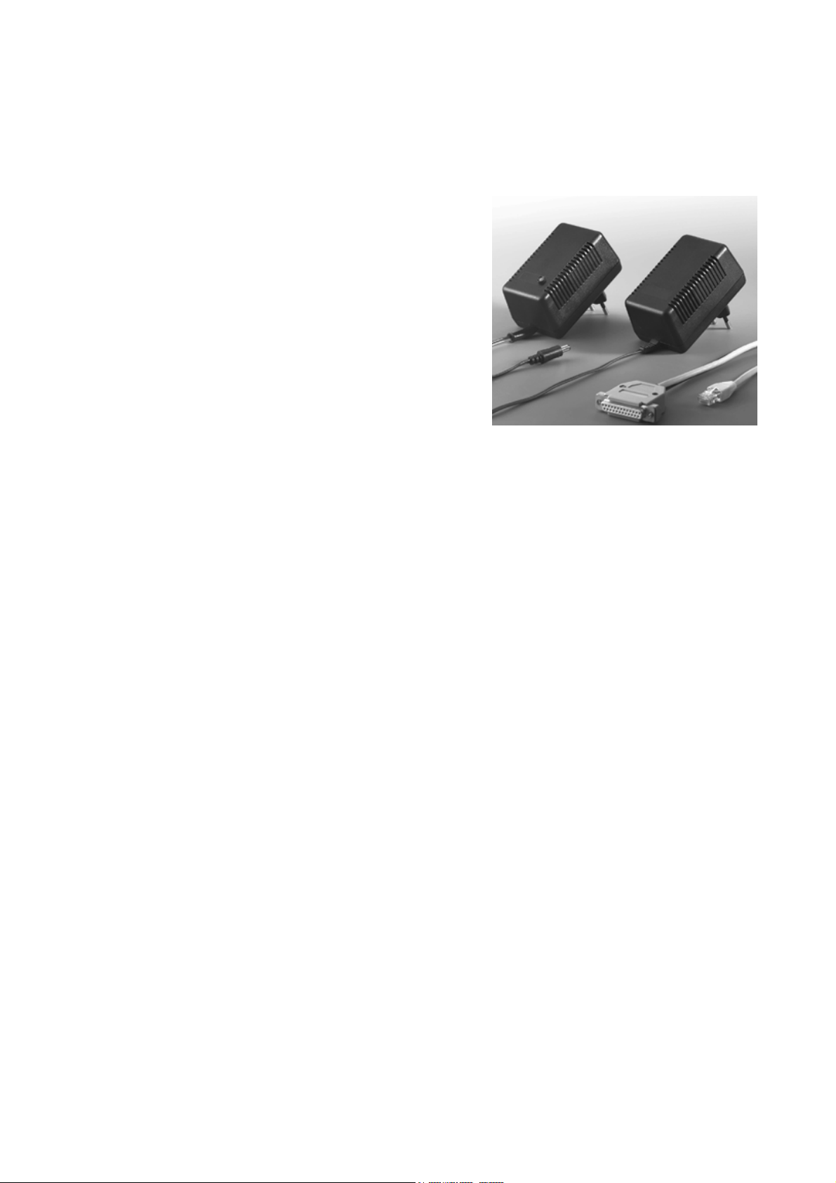
The Communication/Charging-Adapter deals
for connection a mobile terminal to an RS232 port of a PC or other computer. The
Communication/Charging-Adapter is equipped with a fast charging device, which also
deals for loading the integrated mobile
teriminal accus.
Starting Operation
1. Switch of your computer.
2. Connect the RS-232 cable to the desired COM port of your PCs.
3. Connect the Communication/Charging-Adapters main plug to a 220 V AC outlet.
The ground protection must be connected. The Communication/ ChargingAdapters LED glowes green.
4. Now switch on your computer an start your application program.
5. Connect the mobile terminal to the am Communication/Charging-Adapter. The
Communication/Charging-Adapters LED now glows orange. The trickle charging
mode is active an the mobile terminal is ready for data communication.
____________________________________________________________________ aitronic
Page 13

Installation of PC Software MTWIN ___________________________________________
6-1
6. Installation of PC Software MTWIN
The PC Software MTWin is used for data exchage with mobile terminals.
To install the software execute SETUP.EXE in the directory MTWin of the supplied
CD and follow the installation instructions.
You also can download MTWIN from our website www.aitronic.de
Service/Downloads/Communcation Software.
and then
____________________________________________________________________ aitronic
Page 14

System Functions_________________________________________________________
7. Introduction to Operation
The following table shows the standard key functions of devices with
keyboard:
Key Function without Shift Key Function with Shift Key
numerical
7-1
...
0
9
*
SHIFT SHIFT
C CE CANCEL
+ ENTER
By means of the
can be performed as with the keyboard. This can be required with devices missing a
keyboard (
In case of empty entry mask:
In decimal entry fields (quantity
field in Standard Program1):
scan one position backward
scan one position forward
Standard Barcode Menu
PMS 1200
Digits 0 - 9
decimal point.
).
MENU
.
(refer to page 8-20) the same functions
Holding down the shift key and
inputting a decimal number from
32 to 127 any printable ASCII
character can be entered in input
fields which allow these kind of
input.
OFF
HOME
END
____________________________________________________________________ aitronic
Page 15
7-2
_______________________________________________________ System Functions
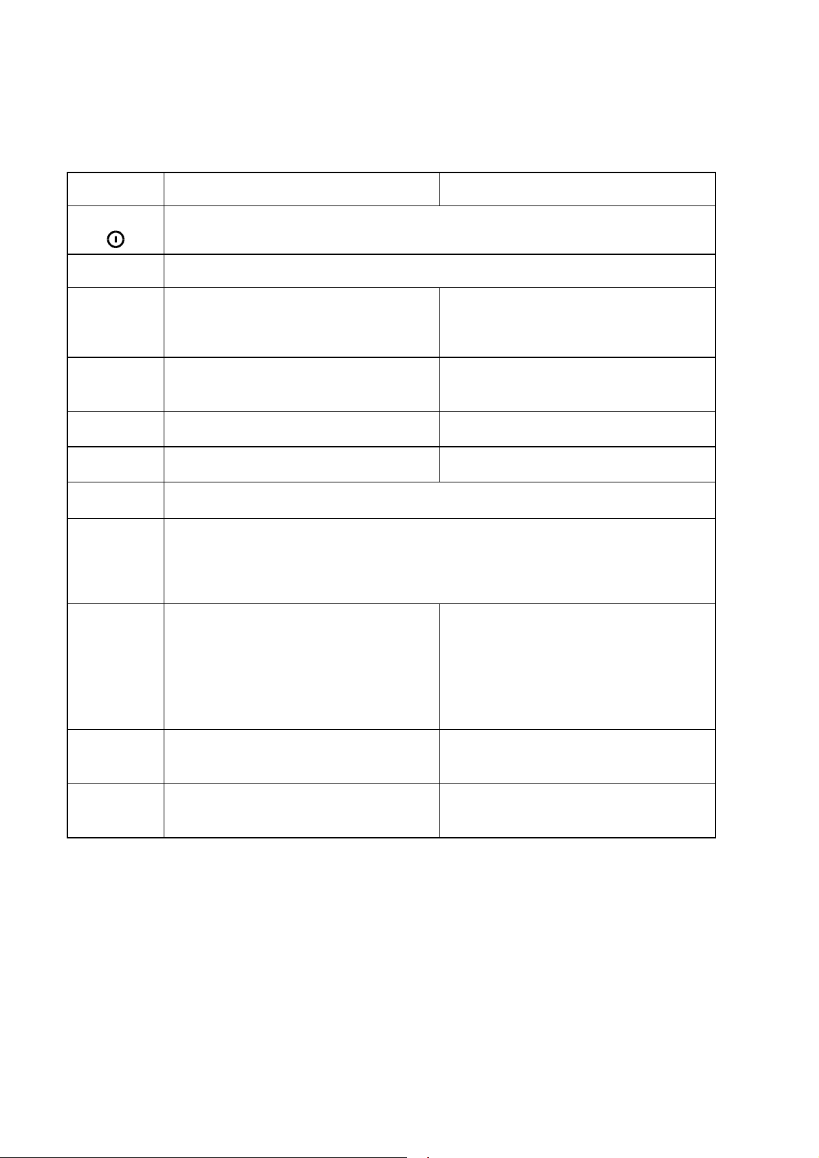
The following table shows the standard key functions of devices with
numerical
Key Function without Shift Key Function with Shift Key
keyboard:
On/Off
SHIFT
0...9
Sonderzeichen
CLR
DEL
↵
Characters 0 - 9
Special Character Alpha Character
CE Alpha Character
CANCEL Alpha Character
Shift
Alpha Character
ENTER
alpha-
MENU
F1...F8
In case of empty entry mask:
In decimal entry fields (quantity field in Standard Program1): decimal
point.
Function Keys
Are not used in the Standard
Software but can be used in the
application programming.
scan one position backward
scan one position forward
Input Mask:
Data memory:
Input Mask:
Data memory:
MENU
Alpha Character
.
Alpha Character
HOME
Alpha Character
END
aitronic ____________________________________________________________________
Page 16

System Functions_________________________________________________________
7-3
Switching on/off
The device switches on in case of
• hitting the keyboard (devices with numerical keyboard) respectively the power on
key (upper left, devices with alphanumerical keyboard),
• pressing the scanner switch,
• connecting the serial interface to a PC where an application is active which has
activated the RTS signal of the serial interface (
and LAP-EC).
In case of inactive signal CTS (this means: no charging/ transmission adapter is
connected or on the PC no application is active which has set the serial interfaces
signal RTS) and for the duration which is adjusted with configuration parameter
Power Off Time
data transmssion with a RF device) the device powers off automatical to economize
the integrated accumulators and therefore to guarantee an long operation time.
Manually switching off is performed by
no operation is performed (hitting of keyboard/scanner switch or
with devices with RF module
not
• holding down key
numerical keyboard
pressing the power on key (upper left) in case of using a device with
•
alphanumerical keyboard
SHIFT
. After releasing both keys the device switches off itself.
and pressing key
.
in case of using a device with
*
LCD Displays
Normally the actual entry mask for article number (Standard Program 1 and 2) and
quantity (only Standard Program 1) is shown. Another display content (program
message or the a stored record in case of scanning through data memory) keeps
staying on LCD until the scanner switch or the keyboard is hit or until the device is
switched off.
With RF devices (only in case of an actual entry mask) the data net activity is shown
on the last LCD position. The symbol ∗ indicates that the device was polled from the
RF server with its address (serial no.). The symbol o indicates that the device was
polled from the RF server with the login address (000000). Normally this two
symbols are changing alternately in case of an logged in device. If only the symbol o
is shown the device is not logged in. If a device resides outside the active RF area
or the RF server is not active no one of those two symbols are shown.
____________________________________________________________________ aitronic
Page 17

7-4
_______________________________________________________ System Functions
Scanner Handling
Testing the Scanner
Hold the scanner above a light surface and press the trigger. Now you should se the
red laser beam on the surface and with the
on.
PMS 1500
Scanning Barcodes
Hold the scanner in front of a barcode and press the trigger. Notice the fol-lowing
operating tips:
• Vary the scanner position in that way that the laser beam sweeps the middle of
the barcode and overlaps it at both sides.
• The larger the barcode, the farther away you should hold the scanner.
• Hold the scanner closer for barcodes which are printed with a higher density.
Hold the scanner not in a right angle to the barcode. In this position light can
•
bounce back into the scanner and influence the decoding perfor-mance or even
prevent decoding at all.
When the scanner has read the barcode
• you will hear the 'Decode Beep' (standard configuration: short double beep),
with the
•
configuration: 3 seconds),
and the laser beam will be switched off.
•
If you follow these instructions and fail to scan read section "If nothing functions"
below.
PMS 1500
the LED 'Good Read' will turn on for a short time (standard
What does the different beeps mean?
Listen to the 'Decode Beep' (standard configuration: short double beep). This
means that the barcode has been decoded successfully.
A long error beep means that the selected function respectively the read barcode is
not valid.
If nothing functions
If you follow previous instructions and fail to scan:
Ensure that the accumulators are charged.
•
• Make sure that the MT is configured for the barcode type which should be read.
• Make sure that the barcodes are not demaged or dirty. Check the barc-ode print
quality.
If you have performed these checks and the barcode still cannot be decoded
contact your authorized distributor.
the LED 'Scanning' should be
aitronic ____________________________________________________________________
Page 18

System Functions_________________________________________________________
7-5
What should be notice with laser light devices
The laser scanners use a low-powerlaser diode for visible laser light. As wiht any
bright light source the user should avoid staring directly into the laser beam.
Momentary exposure to a CDRH Class II laser is not known to be harmful.
The required safety labels are placed below the laser light window and above the
trigger switch.
Manually Data Entry
Enter article number and quantity manual with keys 0…9 The cursor points to the
next entry position.
Use key C (respectiveley
delete the character left beside the cursor.
Use key + to close the entry of the article number and to go to the quanity entry
field.
Use key * (respectiveley
enter the point in case of decimal entries.
Pressing key + when the cursor resides in the quanity entry field the article number
and the quantity will be stored into data memory and the empty entry mask is shown
again.
MENU
in case of devices with alphanumeric keyboard) to
CLR
in case of devices with alphanumeric keyboard) to
Deleting Characters
By pressing key C (respectiveley
keyboard) the character left beside the cursor is deleted. In case of empty entry field
the cursor jumps to the previous entry field. Single digits of a scanned barcode can't
be deleted. In this case there is only the option to delete the entire entry field.
in case of devices with alphanumeric
CLR
Deleting Entry Field
Devices with numerical Keyboard
By holding down key
cursor resides is deleted.
Devices with alphanumerical Keyboard
Press key
instead of
DEL
SHIFT
and pressing key C the entire entry field in which the
SHIFT C
____________________________________________________________________ aitronic
Page 19

7-6
_______________________________________________________ System Functions
Select next Entry Field
If there has been at least one digit entered in the article number field and there is a
quantity field available (Standard Program 1) this may be selected by pressing key
.
+
Closing Entry and storing the Record
If there has been at least one digit entered in the last entry field the whole entry is
closed by pressing key +.
Storing
• the configuration parameter
•
The record is transmitted to the serial interface if the configuration parame-ter
Destination SIO
After storing respectively transmitting the record to the serial interface the next
empty entry mask is shown.
of the record is performed if
Data Destination Memory
or the configuration parameter
signal DTR is not active.
is set and the RS-232 signal DTR is active
Data Destination SIO
.
is set,
is set but the RS-232
Data
aitronic ____________________________________________________________________
Page 20

System Functions_________________________________________________________
8. System Functions
8.1 Cold Start / Initialization
Enable Function Barcodes
8-7
Ö€$X1@ä
Initialization (Cold Start)
Ö€öö$$$$$+ä
Disable Function Barcodes
Ö€$X0<ä
At first power up of the
voltage the initialization takes place with the execution of the following steps:
Boot program start and initialization.
•
• Indication of hardware type with a distinct count of clicks:
2 clicks:
3 clicks:
Test of keyboard/display interface in case of devices with keyboard,
•
Output of a long beep,
•
• RAM Check, is indicated by a distinct count (depends on the size of data
memory) of short beeps:
2 short beeps: 32 K data memory,
8 short beeps: 128 K data memory,
32 short beeps: 512 K data memory.
Flash ROM Check.
•
• In case of errorfree checksums of all 4 Flash ROM Banks the operating system
is started and initialized. Otherwise the device remains in the boot program and
the required software update must be loaded.
Display of the Device Information.
•
−
− Application program name and version (AP),
− Operating System name and version (OS),
− Decoding Software name and version (DS),
−
−
PMS/HTE
PMS 1200
PMS 1500, HTE 1800/1900, MobiScan
Device name and size of data memory,
Boot Program name and version (BP),
Library name and version (LB).
after a software update or after loss of the RAM
,
ATTENTION
be lost and the device will be
initialized completely.
:Stored data will
,
____________________________________________________________________ aitronic
Page 21

8-8
_______________________________________________________ System Functions
− Keyboard Controller name and version (KC).
Loading of
•
user configuration
• Optional input of a
password
.
up to 15 digits (only devices with keybard; with
devices without keyboard the password must be entered via the appropriate
menu function). The password must be confirmed by entering it a second time.
Only in case of confirmity the password is stored. If there is no password used
both inputs can be skipped with key +. The password is used by the operating
system to protect the distinct menu functions.
• RF communication devices now perform an automatic login into the RF net in
case of configuration parameter 'Auto Login' set (is set in the Standard
Program). In case of configuration parameter 'Manual Login' set the login must
be performed via the appropriate menu function.
aitronic ____________________________________________________________________
Page 22

System Functions_________________________________________________________
8.2 Reset Button
8-9
ATTENTION
Don't
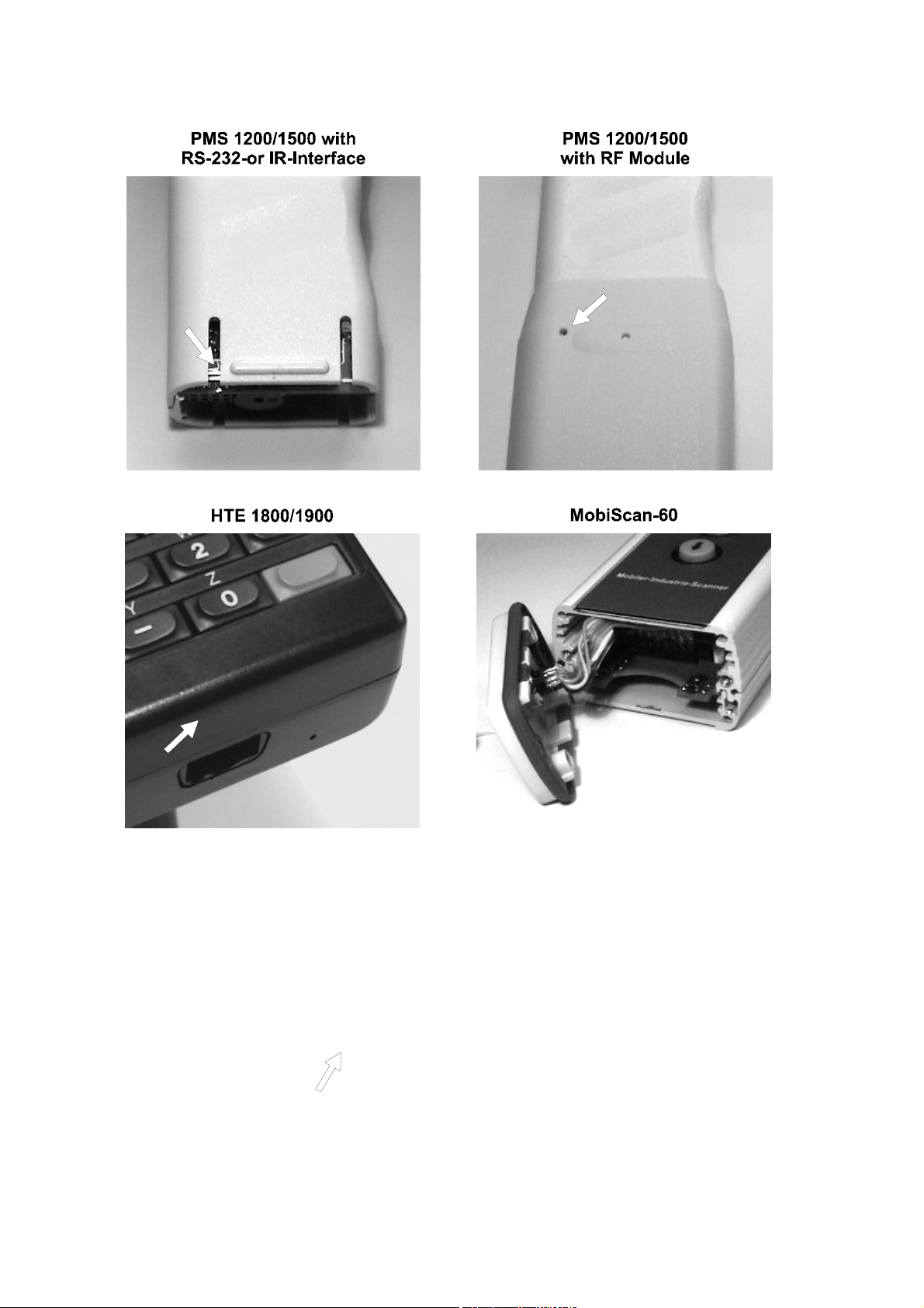
By means of the reset button
•
•
• the boot program can be called.
In this way the device can be resetted. This function is only required when the
device not reacts when the keyboard is hit or when it receives a SIO command.
Two pages ahead this three functions are described detailed.
To get to the reset button
•
•
With all other Mobile Terminals the reset button can be pressed by means of a thin
tool (i.e. bowed up paper clip) through a little hole in the housing. The pictures on
the next page show the position of the reset button at the different Mobile Terminals
types.
press the reset button during the device programmes a Flash ROM sector
(i.e. at software update or when saving the User Configuration). Otherwise the
Flash ROM sector will be destroyed and the software must be loaded new. In
case of sector 1 (contains the boot program) the Flash ROM must be changed.
a warm start can be performed,
a cold start can be performed,
of Mobile Terminals from type PMS 1200/1500 with RS-232- or IR-Interface the
handle grip cap must be removed.
of Mobile Terminals from type MobiScan-60 the casing lid on the right side
must be removed.
____________________________________________________________________ aitronic
Page 23
8-10
_______________________________________________________ System Functions
aitronic ____________________________________________________________________
Page 24

System Functions_________________________________________________________
Warm Start
• Switch device on,
press reset button only
•
• wait until device powers off,
• switch device on. Device works as it was powered off and on again.
one time
,
Cold Start / Initialization
Switch device on,
•
• press reset button,
• wait until device powers off,
• switch device on and press reset button once more during "
press RESET...
• switch device on.
" is displayed (is displayed about 3 seconds),
For Cold Start
8-11
Calling the Boot Program
Perform a cold start (as described above),
•
• Press reset button once more within the RAM test phase.
• If the User Configuration was active "
tion..
Configuration was active "
the User Configuration is activated.
• The device programmes the serial interface with the selected parameters,
remains in the boot program and is ready to load software.
• The configuration for the boot program which was selected in this way is stored
into Flash ROM and is conserved for a new start of the boot program.
• If the default configuration is active a star is displayed at the end of the boot
program name.
." is shown and the Default Configuration is activated. If the User
Saving User Konfiguration..
Saving Default Konfigura-
." is shown and
____________________________________________________________________ aitronic
Page 25

8-12
_______________________________________________________ System Functions
8.3 Battery Low Procedure
In order to continue operation for a distinct time after the battery low level is reached
the first time (either about 3 minutes without switching on the scanner or switching
on the scanner about 25 times), the following 3-Phase-Procedure was implemented:
Phase 0
Phase 1
the Battery Low Counter is incremented if the supply voltage further
or
the Battery Low Counter is decremented if the supply voltage is
Phase 2
the Battery Low Counter is decremented if the supply voltage is
or
if the supply voltage one more time reaches the battery low level the
Normal operation, supply volage above battery low level, internal
Battery Low Counter = 0. If the battery low level is reached the first
time
− the message "
displayed,
− the internal Battery Low
− a change to
Each 7 seconds respectively each time switching on the scanner
stays beyond the battery low level. If the Battery Low Counter
reaches the value 50 "
to
Phase 2
above the battery low level. A change to
Battery Low Counter reaches the value 0.
Each 7 seconds respectively each time switching on the scanner
above the battery low level. A change to
Battery Low Counter reaches the value 0.
Battery Low Counter is set to the value 565, "
is displayed and the device is switched off.
happens and the device is switched off.
Battery gets low, Close Operation!
is set to 25,
" is displayed, a change
Phase 0
Phase 0
Charge Battery!!
happens if the
happens if the
Phase 1
Charge Battery!!
Counter
happens.
" is
"
aitronic ____________________________________________________________________
Page 26

System Functions_________________________________________________________
8-13
8.4 Menu System
The menu system consists of 4 singel menus and has the following structure:
1 APPLICATION 2 DATA MEMORY 3 COMMUNICATION 4 SETUP
Not available! 1 Data Records 1 SIO Parameter 1 SW-Version
2 Data Mem./Byte 2 Hndshk/Prot. 2 Seriennr.
3 Del. Data Mem. 3 Timeouts 3 Datum/Uhrzeit
4 PROT/AutoLogin 4 Password
5 PROT.-Monitor 5 Initialisieren
3 DECT Functions
1 DECT-IPUI
2 DECT-RFPI
3 DECT-RSS/RLQ
4 DECT-Cfg.prog.
5 DECT-Cfg.snd.
6 LAP Monitor
7 DECT-SubsOnAir
In case of an entered password the menu items marked grey can be executed only
by entering this password.
Calling/leaving the Menu System
Devices with numerical Keyboards
The menu system is called with key
*
and also left in this way. Calling the menu
system is only possible in case of empty entry mask. When entering the menu
system the menu item which was selected when leaving the menu system the last
time is displayed.
Devices with alphanumerical Keyboards
*
Press key
MENU
instead of key
.
Selecting Menus
Selecting the next menu is done by holding down key
SHIFT
Leaving menu 4 menu 1 is selected. Selecting the previous menu is done by holding
down key
SHIFT
and pressing key
. Leaving menu 1 menu 4 is selected. In each
menu the last menu item keeps selected.
The desired menu can also be selected directly by holding down key
pressing key 1…4.
and pressing key.
SHIFT
and
____________________________________________________________________ aitronic
Page 27

8-14
_______________________________________________________ System Functions
Selecting Menu Functions
The next menu item is selected with key
menu item of the next menu is selected. The previous menu item is selected with
key
selected.
The desired menu item can also be selected directly with keys 1...9. If the desired
menu item is not available the last menu item of the actual menu is selected.
. Leaving the first menu item the last menu item of the previous menu is
. Leaving the last menu item the first
Executing Menu Functions
The actual menu function is executed with key +.
Returning to Menu System
After execution of menu functions which don't leave the menu system respectively
which lead to other display outputs an exit from the the menu system can be
performed by
• pressing key
when using
• pressing key +, CLR (only if this key isn't used for other functions) or DEL when
using
devices with alphanumerical keyboard
devices with numerical keyboard
(only if this key isn't used for other functions) or
+, C
.
.
SHIFT C
Menü: 1 APPLICATION
Not available!
This menu is normally not available. But it may be configured by means of PC
programs MTWIN 2.0 whereby all of the system menu functions can be used (refer
to
ECHNICAL MANUAL
T
).
aitronic ____________________________________________________________________
Page 28

System Functions_________________________________________________________
8-15
Menü: 2 DATA MEMORY
1 Data Records
2 Data Mem./Byte
Displaying the amount of occupied and free data memory in byte. The
3 Del. Data Mem.
Displaying the amount fo stored and deleted records. The appropriate
function keys return back to the menu system.
appropriate function keys return back to the menu system.
After confirming the question "
the data memory is deleted and the first input mask of the selected
+
program is displayed. Any other key returns back to the menu system.
Delete Data Memory?
" with function key
Menü: 3 COMMUNICATION
1 SIO Parameter
Displaying the adjusted baudrate and parity bit. The appropriate function
keys return back to the menu system.
2 Hndshk/Prot.
Displaying the adjusted SIO handshake respectively protocol. The
appropriate function keys return back to the menu system.
3 Timeouts
Displaying the adjusted timeout(s) depending on the SIO handshake re-
spectively protocol. The appropriate function keys return back to the menu
system.
4 DECT Functions
Calling sub menu ‚DECT Functions’.
____________________________________________________________________ aitronic
Page 29

8-16
_______________________________________________________ System Functions
Sub-Menü: 3 DECT Functions
1 DECT-IPUI
Displaying the IPUI (International Portable User Identification) of the
integrated DECT module.
2 DECT-RFPI
Displaying the 6 entered RFPI (Radio Fixed Part Identification) of the
integrated DECT module, as well as the status (0=inactive, 1=active) right
below on the LCD. The base stations RFPI, to which an active connection
existst, is marked with *. When pressing key
displayed. After pressing key C resp.
With
SHIFT C
resp.
the function will be leaved.
DEL
CLR
ENTER
the actual entry may be modified.
3 DECT-RSS/RLQ
Displaying the
DECT connection. This function may be used to „measure out“ the area in
which the DECT communication should take place ,.
adio Signal Strength and the Radio Link Quality of the active
R
4 DECT-Cfg.prog.
Programming the loaded Konfiguration into the DECT module.
5 DECT-Cfg.snd.
Sending the loaded DECT module configuration via the serial interface.
6 LAP Monitor
Displaying the amount of the sent/received LAP-EC protocol data blocks as
well as the repeated data blocks.
7 DECT-SubsOnAir
Calliing the DECT
connection to next reachable base station which RFPI is entered and
activated will be established automatical.
Subs
cription on
procedure. With this procedure a
Air
the next RFPI will be
aitronic ____________________________________________________________________
Page 30

System Functions_________________________________________________________
8-17
Menü: 4 SETUP
1 SW Version
Displaying the device information on the LCD. The device information con-
sists of three displays and is scrolled forward by function key +. With devices
missing a keyboard the scrolling happens automatical.
2 Serial Number
Displaying the 6 digit serial number which is permanently stored in Flash-
ROM. The appropriate function keys return back to the menu system.
3 Date/Time
Conitinous displaying of date and time. By pressing key C (respectively
pressing key
date/time can be modified. The appropriate function keys return back to the
menu system.
4 Password
Displaying the password. By pressing key C (respectively pressing key
when using
modified. To confirm this input the password must be entered a second time.
The appropriate function keys return back to the menu system.
devices with alphanumerical keyboard
5 Initialize
After confirming the question "
the boot program is called (→ software update). Any other key returns
+
back to the menu system. This command can only be executed in case of
empty or transmitted data memory.
After calling the boot program initialization of the device takes place (→ cold
start) even if there was no software update loaded.
when using
CLR
devices with alphanumerical keyboard
) the password can be
Exec. Boot Prog/Initialize?
" with key
)
CLR
____________________________________________________________________ aitronic
Page 31

8-18
_______________________________________________________ System Functions
8.5 Function Barcodes
Commands
Show Software Version
Öü$I5ä
Transmit Data
Öü$D&ä
Set Data Transmission Lock
Öü$F1pä
Reset Data Transmission Lock
Öü$F0lä
Displaying the device information. With a
ling can be stopped with the scanner switch.
Transmits data via the serial interface (as SIO com-
mand D).
Setting the Data Transmission Lock (as SIO com-mand
T1
Resetting the Data Transmission Lock (as SIO com-
mand T0).
).
PMS
scrol-
Enable Function Barcodes _____________________________________________
Öü$X1?ä
aitronic ____________________________________________________________________
Page 32

System Functions_________________________________________________________
8-19
Program Selection
The selection of another program is only allowed in case of empty data memory!
The selection of application programs 1 - 10 requires a special application pro-gram
which provides this function.
Standard Program 1 Standard Program 2
Article Number/Quantity Article Number
Öü$A0]ä
Appl.-Prog. 1 Appl.-Prog. 6
Öü$A1aä
Appl.-Prog. 2 Appl.-Prog.7
Öü$A2eä
Appl.-Prog. 3 Appl.-Prog. 8
Öü$A3iä
Appl.-Prog. 4 Appl.-Prog. 9
Öü$AA:ä
Öü$A6uä
Öü$A7yä
Öü$A8}ä
Öü$A4mä
Appl.-Prog. 5 Appl.-Prog. 10
Öü$A5qä
____________________________________________________________________ aitronic
Öü$A9ä
Öü$A:…ä
Page 33

8-20
_______________________________________________________ System Functions
Standard Barcode Menu
Öüö1Lä
1 *
Öüö2Oä
2 SHIFT
Öüö3Rä
3 SHIFT
Öüö4Uä
4
Öüö5Xä
5
Öüö6[ä
6
Öü$Zhä
Öü$KAXä
Öü$KEhä
Öü$KUAä
Öü$KIxä
Öüö7^ä
7
Öüö8aä
8 C
Öüö9dä
9 SHIFT C
Öüö0Iä
0 +
Öü$H2ä
Öü%A†ä
Öü$MAä
aitronic ____________________________________________________________________
Page 34

System Functions_________________________________________________________
Function Keys
8-21
Öü$0Qä
SHIFT 0
Öü$1Tä
SHIFT 1
Öü$2Wä
SHIFT 2
Öü$3Zä
SHIFT 3
Öü$4]ä
SHIFT 4
Öü$5`ä
SHIFT 5
Öü$6cä
SHIFT 6
Öü$7fä
SHIFT 7
Öü$8iä
SHIFT 8
Öü$9lä
SHIFT 9
____________________________________________________________________ aitronic
Page 35

8-22
Alpha Characters
_______________________________________________________ System Functions
Öüö032!ä
Space *
Öüö033&ä
! +
Öüö034+ä
" ,
Öüö0350ä
# -
Öüö0365ä
$ .
Öüö042%ä
Öüö043*ä
Öüö044/ä
Öüö0454ä
Öüö0469ä
Öüö037:ä
% /
Öüö038?ä
& :
Öüö039Dä
' ;
Öüö040‚ä
( <
Öüö041öä
) =
Öüö047>ä
Öüö058Gä
Öüö059Lä
Öüö060#ä
Öüö061(ä
aitronic ____________________________________________________________________
Page 36

System Functions_________________________________________________________
8-23
Öüö062-ä
> I
Öüö0736ä
Öüö0632ä Öüö074;ä
? J
Öüö0647ä Öüö075@ä
@ K
Öüö065<ä Öüö076Eä
A L
Öüö066Aä
B M
Öüö077Jä
Öüö067Fä
C N
Öüö068Kä
D O
Öüö069Pä
E P
Öüö070'ä
F Q
Öüö071,ä
G R
Öüö078Oä
Öüö079Tä
Öüö080+ä
Öüö0810ä
Öüö0825ä
Öüö0721ä
H S
____________________________________________________________________ aitronic
Öüö083:ä
Page 37

8-24
_______________________________________________________ System Functions
Öüö084?ä
T -
Öüö085Dä
U `
Öüö086Iä
V a
Öüö087Nä
W b
Öüö088Sä
X c
Öüö095Hä
Öüö096Mä
Öüö097Rä
Öüö098Wä
Öüö099\ä
Öüö089Xä
Y d
Öüö090/ä
Z e
Öüö0914ä
[ f
Öüö0929ä
\ g
Öüö093>ä
] h
Öüö100uä
Öüö101zä
Öüö102üä
Öüö103„ä
Öüö104"ä
Öüö094Cä
^ i
aitronic ____________________________________________________________________
Öüö105'ä
Page 38

System Functions_________________________________________________________
8-25
Öüö106,ä
j u
Öüö1071ä
k v
Öüö1086ä
l w
Öüö109;ä
m x
Öüö110yä
n y
Öüö1175ä
Öüö118:ä
Öüö119?ä
Öüö120}ä
Öüö121‚ä
Öüö111~ä
o z
Öüö112ƒä
p {
Öüö113!ä
q |
Öüö114&ä
r }
Öüö115+ä
s ~
Öüö122öä
Öüö123%ä
Öüö124*ä
Öüö125/ä
Öüö1264ä
Öüö1160ä
t
____________________________________________________________________ aitronic
Page 39

8-26
_______________________________________________________ System Functions
8.6 Charging the integrated Accumulators
The integrated accus should be charged periodical (in case of intensive usage at
least once a day). If the accu capacity runs empty because the accus were not
charged the device displays the message "
Operation!
tively the device can be operated with still for about 3 minutes. Then the device
displays the message "
Detailed informationen concerning special charging devices refer to the
MANUAL FOR MOBILE TERMINALS OF PMS, HTE AND MOBISCAN SERIES
". After this message about 25 barcodes can be still read respec-
Charge Battery!!!" and switches off automatical.
Battery gets low, Close
TECHNICAL
.
aitronic ____________________________________________________________________
Page 40

System Functions_________________________________________________________
8.7 Error Messages
Error Message Description Cause respectively Help
8-27
Battery gets low
Close Operation!
Charge
Battery!!!
BP: MTBOT vvv
Err nn, load SW!
The accus only contain a
remaining capacity. The first
time this message is
displayed with a 5 seconds
long pulsing beep sequence.
Within this duration the Good-
Read-LED is switched on.
During the following operation
this message is displayed
with a shorter beep sequence
every 7 seconds respectively
after each scan.
The accus doesn't supply the
required voltage.
An error was detected during Flash-ROM-Check. The error
code nn contains the number(s) of the
(bitmapped). Perhaps a software update was broken or a
Software Module is missing.
Help: Execute software update once more.
In case of error code Bit 4 = 1 a boot program checksum error
was detected. In this case the boot program must be loaded
once more.
The current procedure should
be closed and the MT should
be connected to mains by
means of the
Charging/Transmission Adpater
because after this error
message only about 25
barcodes can be scanned
respectively there is only a
remainding operation time of
about 3 minutes before the
device displays the error
"
message
Battery
Connect
Charging/Transmission Adapter
erroneous
Charge
"
and then powers
off.
MT
with
to mains.
banks
BP Version < 5.0
required!
Data Memory
contains Data!
Data Memory
full!
Error Message Description Cause respectively Help
____________________________________________________________________ aitronic
An attempt was made to load
an operating system version
< 5.0.
A function that requires the
data memory cannot be
executed because data are
stored.
Data memory is full.
At first load the required boot
program version, then repeat
the operating system software
update..
Transmit data and execute
desired function once again.
Transmit data and delete data
memory.
Page 41

8-28
_______________________________________________________ System Functions
Receive
Timeout!
Function not
implemented!
Handshake
Timeout!
When receiving data (i.e.
software update) there was a
delay longer than Rx
Timeout
Selected function is not
implemented in used device
The RS-232 Handshake
(XON/XOFF respectively
RTS/CTS) was missing for a
duration longer than
programmed under HndShk
Timeout (configuration
(configruation
parameter).
type.
parameter).
Check Computer and
Charging/Transmission
Adapter. Perhaps enlarge Rx
Timeout
parameter). Execute desired
function once again.
Selected function cannot be
executed (i.e. switching LCD
ilumination on/off with
The connected computer
(application) is not active
anymore, doesn't handle the
handshake correct, produces to
long time delays or the
Charging/Transmission-Adapter
Try to enlarge
Timeout
(configruation
PMS 1200
is erroneous.
(configuration
parameter).
).
HndShk
Invalid
AP Version!
Invalid
DS Version!
No connection!
Mask Buffer
Overflow!
An attempt was made to load
an application which was
compiled for another
operating system version.
An attempt was made to load
a Decoding Software version
which was compiled for
another operating system
version.
Missing RS-232 signal CTS.
The mask buffer got
overflowed.
At first load the required
operating system version, then
repeat the loading of the
application.
At first load the required
operating system version, then
repeat the loading of the
Decoding Software .
The connected computer
(application) is not active
anymore or the Charging/
Transmission Adapter is
erroneous.
Error in the application
program. When buffering input
masks there must also be
precautions of removing mask
numbers from the mask buffer
again.
Error Message Description Cause respectively Help
aitronic ____________________________________________________________________
Page 42

System Functions_________________________________________________________
8-29
Not possible
with S/N:000000!
No OS loaded!
Par.Overr.Fram.
Error!
Protocol
abort!
S-File Checksum
Error!
S-File Format
Error!
Transmission
Timeout!
The device resides in Test
Mode (serial no. '000000' ).
The executed function
requires a serial no. different
from '000000' (i.e. LAP-EC).
An attempt was made to start
a non existing operating
system.
A character with erroneous
parity or stop bit was received
via the serial interface.
XModem or LSV-2 protocol
was aborted.
Error in S-File-Checksum
detected.
Erroneous S-File fomat. Check S-File and execute
While communicating via
LAP-EC the transmission
buffer was full for a duration
longer than the time defined
Tx Timeout/LAP-EC
by
(configuration parameter).
Program serial no. and execute
desired function once more.
Load operating system and
application.
Check SIO parameter and set it
to the correct values. Start
aborted procedure once more.
Start aborted procedure once
more.
Check S-File and execute
software update once more.
software update once more.
The application which
communicates with MT
produces to long time delays
while receiving data. Try to
enlarge Tx Timeout/ LAP-EC
(configuration parameter) or
solve the problem in the
application.
LAP-EC: Blkcnt
Error, press +
LAP-EC: Block
Counter Error!
LAP-EC: No
Communikation!
LAP-EC
not active!
Fatal error while
communicating via LAP-EC in
the operating system.
Fatal error while
communicating via LAP-EC in
the boot program.
RF net not active respectively
MT resides outside of the RF
area.
Refer to explanation (1).
Selected function requires
LAP-EC.
MT
The
function) logged in again. Start
PC software again. The block
counters will be resetted in that
Perform cold start of the MT.
Start PC software again. The
block counters will be resetted
Check NARF and RF module of
respectively return with MT
back to the active RF area.
Activate LAP-EC and execute
desired function once more.
must be manual (menu
way.
in that way.
MT and start PC software
____________________________________________________________________ aitronic
Page 43

8-30
_______________________________________________________ System Functions
Error Message Description Cause respectively Help
LAP-EC:
Not logged in!
Line Buffer
Overflow!
MT not logged in.
Refer to explanation (1).
The line buffer for the serial
interface has got overflowed
because there were more
than 255 charcters received
without a CR.
Check initialization file on the
PC and start PC software
again, the RF Scanner will be
logged in again.
The application which
communicates with MT sends
more than 255 characters
without a CR.
Explanations
(1) These error messages are not displayed with the Standard Program but can be
activated in a special application by means of the corresponding configuration
parameter.
aitronic ____________________________________________________________________
Page 44

System Functions_________________________________________________________
8-31
8.8 Error Diagnostics
The following table should help with errors that are not indicated by an error message but appearing as unexpected behaviour of the MT.
Symptom Cause respectively Help
Barcodes are read badly
Serial communication
is erroneous
Serial communication
doesn't work at all
•
Screen at the front of the device (PMS) has become dirty or
scratched,
•
Barcode printed badly, dirty or scratched.
•
Too much barcode types activated. Activate only those
barcode types which are required.
Serial interface parameters (baudrate, parity at MT or PC side
or both) are not selected correct .
With Charging/Communication Adapter (RS-232)
•
Charging/Transmission Adapter not connected to mains,
•
Connector of Charging/Transmission Adapter not
connected completely to the device,
•
Charging/Transmission Adapter not connected correctely to
the PC,
•
Serial interface of MT or PC erroneous.
With Infrared Cradle
•
Device not pushed completely into the Cradle,
•
Cradle not connected correctely to the PC,
•
Infrared interface of MT or Cradle dirty or erroneous,
•
Serial interface of the PCs erroneous.
With RF or RS-485-Cradle or INAP and LAP-EC
•
NARF respectively. NAC not switched on or not connected
correctly,
•
LAP-EC and/or concerning application on PC not active,
•
Device is not logged in (at the right bottom of LCD only the
symbol o is shown),
•
Device resides outside the RF area (at the right bottom of
LCD neither o nor * is shown),
____________________________________________________________________ aitronic
Page 45

_________________________________________________________ Software Update
9-2
For a software update the following steps must be performed:
• Connect device via charging/transmission-adapter to the desired COM to the
PC.
• Start program MTCON on the PC.
• If COM2 should be used this must be selected under
faces
• Read the two following function barcodes:
Enable Load default
Function Codes Configuration
.
Options/Serial Inter-
Öü$X1?ä
• Load desired S-File with function
If the required boot program version isn't already loaded (refer to table on
•
previous page) load boot program MTBOT.S with function
Update/S-File
• When the boot program prompts ready load standard software MTSTDxxx.S
with function
Although the standard software MTSTD is configurable concerning hard- and
software (exception: MTSTD can't be configured for the PSC Scanner with serial
LCD interface, with this device the special S-File must be loaded) for the different
device and communication types S-files are available. The nomenclature of the Sfiles conforms to the following sheme:
MTSTDgp.S
Device Type
_ PMS 1200, PMS 1500
P
The underline '_' is only used if there are more parameters different from the
underline before the file extension.
Functions/Software Update/S-File
.
Functions/Soft-ware Update/S-File
SIO Protocol
no SIO Protocol,
_
F
G
H
LAP-EC/RF,
LAP-EC/RS-485-Cradle,
LAP-EC/INAP.
PSC Scanner
with serial LCD interface.
and hardware compatible devices,
Öüö*/öööösä
.
Functions/Soft-ware
.
aitronic ____________________________________________________________________
Page 46

Software Update__________________________________________________________
9-3
Examples:
MTSTD.S
Standard Software for
PMS 1200/1500
and
compatible devices without SIO Protocol for
software update with
MTCON
or terminal
emulation program.
MTSTD_G.S
Standard-Software für
PMS 1200/1500
and
compatible devices for connection to a RS485-Network. A software update must be
performed with
MTCON
or a terminal
emulation program.
The boot program (from v4.4) runs the software update with the actual parameters
(SIO parameter, protocol), so that it is possible to load software update via LAP-EC.
When the boot program is called it stores the actual parameters in Flash-ROM, so
that even after breaking off a software update a new run with these parameters is
possible. If it is not possible to run the software update with the actual parameters
the boot program can be set to the standard parameters if the reset button is
pressed during the RAM test after cold start.
____________________________________________________________________aitronic
Page 47
Technical Data ___________________________________________________________
10. Technical Data
Mobile Terminals PMS 1200/1500
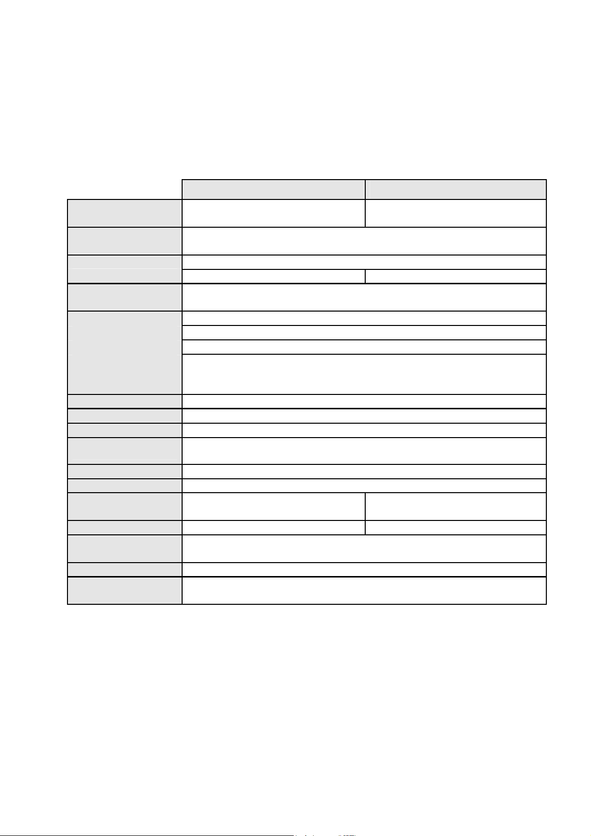
PMS 1200 PMS 1500
10-1
Keyboard
[Rows x Columns]
LC Display
[Lines x Character]
Data Memory
(RAM)
Program Memory
(Flash ROM)
Serial
Interface
Real Time Clock
Power Supply
Audio Signal
Barcode Formats
Parametrization
Programming
Measures
LxBxH [mm]
Weight
Environmental
Temperature.
Storing
Relative
Humidity
- 4x4
2x16 with background illumination
128 K
512 K
128 K for System Software and Application Program
RS-232, 300 - 19200 Bd
RS-485, 300 - 19200 Bd
Face-to-Face Infrared with IR Cradle, 300 - 9600 Bd
connectable RF transceiver module, carrier frequency 433 or 434 MHz,
active area up to 200 m (depending on environment), 4800 Bd,
weight 50 g, length 60 mm
day of week, date and time with seconds resolution
5 NiCd cells 1.2 V, 600 mAH, quick chargable
beeper, configurable volume
EAN/UPC, CODE 39, CODE 128, Code 2 of 5 int/std/matrix, Codabar,
CODE 93, Code 11
with barcode menu or PC software MTWIN (v2.0 and higher).
free application programming with C Development Tool MTC
100x70x170 100x70x185
340 g 400 g
5 - 50º C
-40 - 70º C
5 - 95%, not condensing
____________________________________________________________________aitronic
Page 48
__________________________________________________________ Technical Data
10-2
Mobile Terminals HTE 1800/1900 and MobiScan-6x/8x
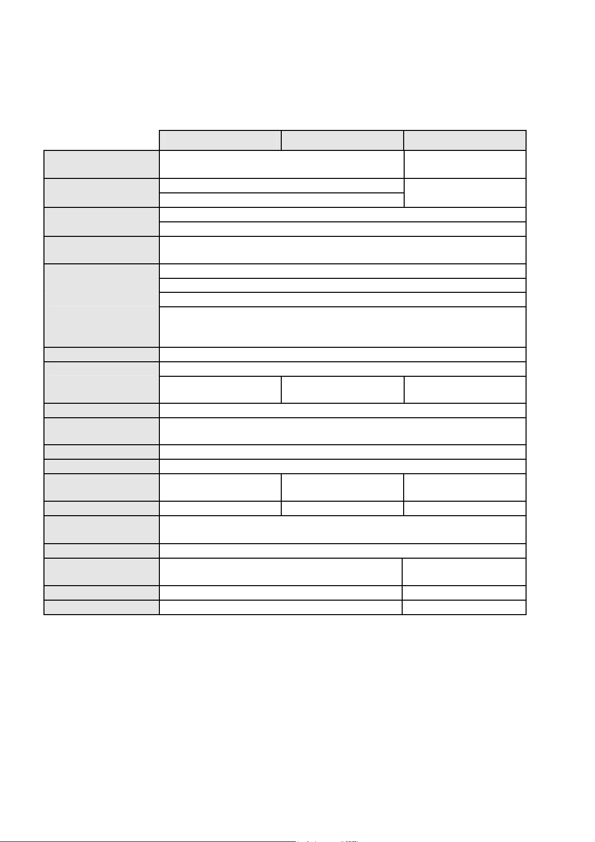
HTE 1800 HTE 1900 MobiScan-6x
Keyboard
[Rows x Columns]
LC Display
[Lines x Character]
Data Memory
(RAM)
Program Memory
(Flash-ROM)
Serial
Interface
Infrared up to a distance to about 50 cm with INAP, 19200 Bd
Real Time Clock
Power Supply
changable 9 V block
Audio Signal
Barcode Formats
Parametrization
Programming
Measures
LxBxH [mm]
Weight
Environmental
Temperature.
Storing
Relative
Humidity
Housing Material
Protection Class
2x16 without background illumination 2x16 with back-
4x20 with background illumination ground illumin.
128 K for System Software and Application Program
Only HTE 1900 with NiMH-Accus
frequency 433 or 434 MHz, active area up to 200 m
day of week, date and time with seconds resolution
3 NiMH cells 1.2 V, 580 mAH, quick chargable
EAN/UPC, CODE 39, CODE 128, Code 2 aus 5 int/std/matrix,
with barcode menu or PC software MTWIN (v2.0 and higher).
free application programming with C Development Tool MTC
156x76x35 156x76x160 220x60x35
295 g 380 g 450 g
5 - 95%, not condensing
7x4 + 2 2
128 K
512 K
RS-232, 300 - 19200 Bd
RS-485, 300 - 19200 Bd
: RF transceiver module, carrier
(depending on environment), 4800 Bd.
battery
beeper, configurable volume
Codabar, CODE 93, Code 11
5 - 50º C
-40 - 70º C
no restriction
ABS Aluminium
- IP 65
aitronic ____________________________________________________________________
Page 49

Technical Data ___________________________________________________________
10-3
Scanner Modules
Mobile
Terminals
Resolution
5,0 mil/0,13 mm 5,7 - 6,4 cm 5,7 - 6,4 cm
6,0 mil/0,15 mm 8 - 13 cm
7,5 mil/0,19 mm 5 - 20 cm 4,5 - 15 cm 4,5 - 15 cm
10 mil/0,25 mm 2.5 - 25 cm 4,1 - 18 cm 4,1 - 18 cm
100% UPC 4,7 - 25 cm 4,7 - 25 cm
20 mil/0,51 mm 0 - 36 cm 0 - 16 cm 0 - 16 cm
30 mil/0,76 mm 13 - 76 cm
40 mil/1,02 mm 0 - 51 cm 0 - 51 cm
55 mil/1,40 mm 0 - 64 cm 0 - 64 cm
Scan Distance
Laser Power
Printing Contrast
Scan Rate
Scan Angle
max. Pitch
max. Scew
Laser Diode
Wave Lenght
Sun Light
Halogen Light
Flourec. Light
Standard Optic
PSC-
PMS 1200/1500 HTE 1800/1900
0,94 mW
min. 50 % min. 20 % min. 20 %
35 Scans/s
bis 60º bis 60º
±
55º
±
65º
670 nm 650 nm 650 nm
Immunity against environmental light
107640 Lux 107640 Lux
4844 Lux 4844 Lux
1)
1) The technical data of the other types are contained in the appropriate PSC data
sheets.
2) The laser beam of this module can picture a narrow ellipses instead of a
horizontal line. There can also be a picture of a small dot near the laser beam
line. These phenomens don't prejudice the scanning performance at all.
Symbol
SE 900
Depth of Field
±
0,06 mW
36 (±3) Scans/s 36 (±3) Scans/s
±
60º
±
65º
Symbol
SE 923
HTE 1800/1900,
MobiScan-6x/8x
0,94 mW
±
0,06 mW
±
60º
±
65º
____________________________________________________________________aitronic
Page 50
Accessories _____________________________________________________________
11. Accessories
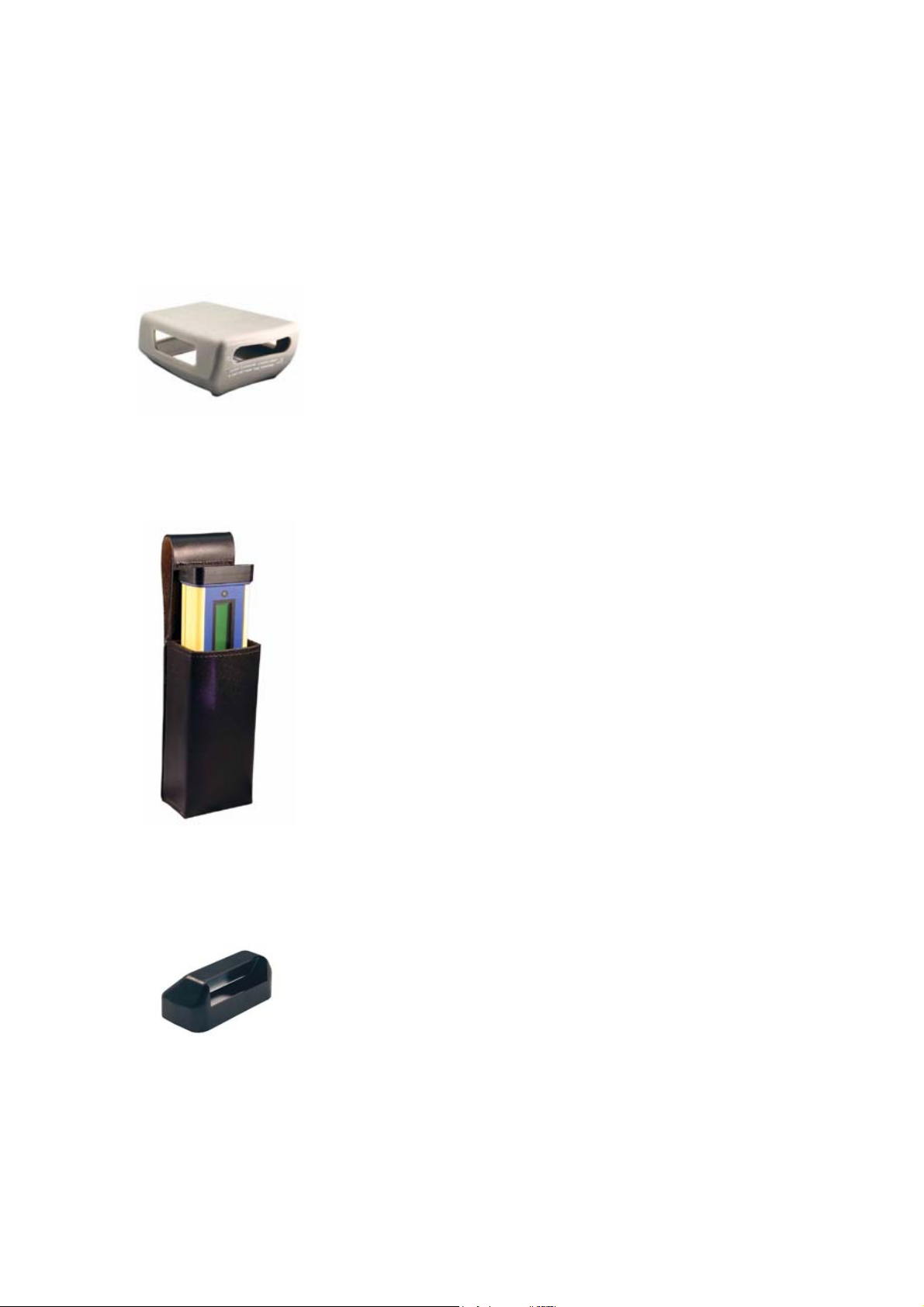
Protection cap for PMS
Rubber protection cap to soften beats onto the PMS
Belt Holster for MobiScan 6x
11-1
The belt holster made of leather makes it possible
carrying the MobiScan at the belt, i.e. when both
hands must be free for working.
Redirection Optic for HTE
The mirror optic for the laser scanner makes it
possible to scan horziontal oriented barcodes in an
ergonomic way (i.e. out of order lists).
____________________________________________________________________aitronic
Page 51
____________________________________________________________ Accessories
11-2
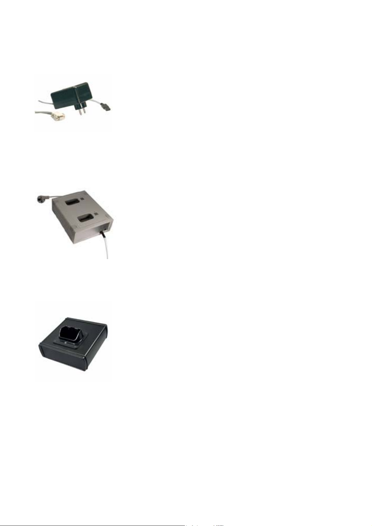
RS-232 Cable for HTE and MobiScan
Steckverbindung:
zum Scanner: HCL Interconnectron
zum Computer: SubD 9 pol.
2-Bay Charging Cradle for HTE 1900
Fast Charging Cradle for HTE 1900
Max. charging time 1,5 h
Interface: RS-232, RS-485, LAN (Ethernet)
Cradle MobiScan 6x PTR
Communication/Charging Cradle for MobiScan 6x
Max. charging time 1,5 h
Interface: RS-232, LAN (Ethernet)
aitronic ____________________________________________________________________
Page 52
Accessories _____________________________________________________________
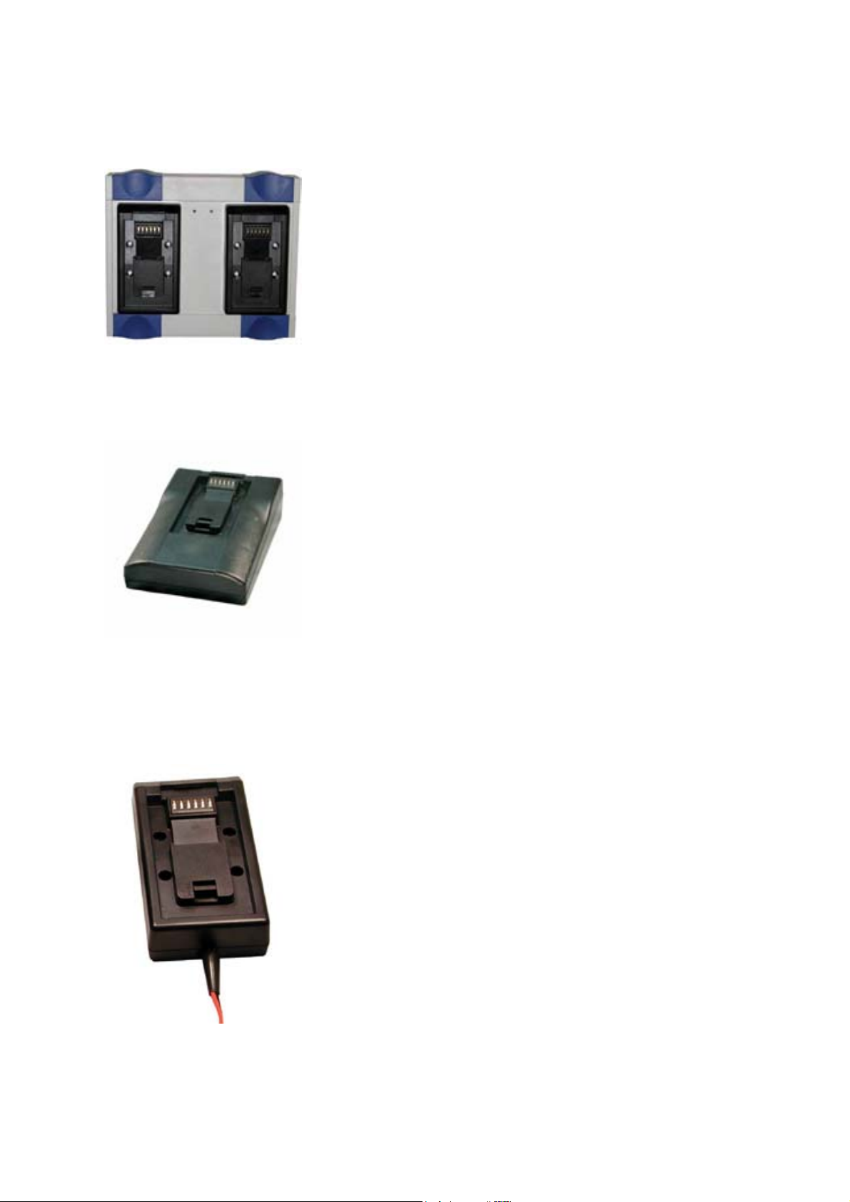
2-Bay Cradle MobiScan 6x/8x UDS
Charging Cradle with two UDS connectors
Charging Time: 1,5 h
Interface: RS-232, RS-485, LAN (Ethernet)
1-Bay Cradle UDS with RS-232 and LAN Interface
Charging Cradle with UDS connector
Charging Time: 1,5 h
Interface: RS-232, LAN (Ethernet)
11-3
Cradle 1-fach UDS
Charging Cradle with UDS connectors
Charging Time: 1,5 h
Accesspoint for DECT RF Network
____________________________________________________________________aitronic
Page 53

____________________________________________________________ Accessories
11-4
RF Module: MD-32
Interfaces: RS-232, LAN
Connection up to 16 mobile terminals per each
Accesspoint possible
aitronic ____________________________________________________________________
Page 54

Recycling Orders _________________________________________________________
12-1
12. Recycling Orders
Battery Order
Following the 'Verordnung über die Rücknahme und Entsorgung gebrauchter
Batterien und Akkumulatoren’ (shortcut: Batterieverordnung - BattV) BGBl I page
658 from 27.3.1998 manufacturers and distributors only may put batteries and
accumulators containing poisonous material into circulation if they ensure that the
consumer may return it back after usage. This Battery Order is also valid for salvage
devices which contain fixed installed batteries and accumulators.
In the same manner the consumer is bound to recycle used batteries and
accumulators following this Battery Order.
The complete (german) Battery Order may be inspected under Internet address
http://www.umweltrecht.de/recht/abfall/bat.htm
Our home page contains a corresponding link.
Therefore we offer a feeless returning back service (free to the door) for used
batteries and accumulators coming from our devices and also for complete salvage
devices coming from us which contain fixed installed batteries and accumulators to
our clients.
IT Salvage Devices Order
At the time this manual was printed only a draft of the ‘Verordnung über die
Entsorgung von Geräten der Informations-, Büro- und Kommunikationstechnik’ (ITAltgeräte-Verordnung - ITV) which was passed from the Bundeskabinett at
19.5.1998. Following this draft manufacturers and importers must take back salvage
IT devices to recycle it.
The draft of the IT Salvage Devices Order may be inspected under Internet address
http://www.nordschwarzwald.ihk.de/umwelt/un-na2-98.htm
Our home page contains a corresponding link.
We offer to our clients already now a feeless returning back service (free to the
door) for salvage devices which come from our production.
____________________________________________________________________aitronic
Page 55

Additional Manuals ________________________________________________________
13-1
13. Additional Manuals
for Mobile Terminals of PMS, HTE, and MobiScan Series,
Single Connection Components, Network Components
and Accu Charging Devices
Manual for device administrators and service purposes.
A
PPLICATION PROGRAMMING MANUAL
for Mobile Terminals of PMS, HTE, and MobiScan Series
This manual is included in the standard delivery package of
Kit for MTs) and deals as a reference for MT application programmer.
C
ONNECTIVITY
with Mobile Terminals of PMS, HTE, and MobiScan Series,
Single Connection Components, Network Components
and Accu Charging Devices
This manual contains an overview about Mobile Terminals of PMS, HTE and
MobiScan Series, about the single connection components Communication/
Charging Adapter and IR Cradle, about network components NAC, NARF, IR
Cradle, INAP, NA-485 and about accu charging devices and shows the application
of these devices. Another chapter contains applications examples.
& A
PPLICATIONS
ECHNICAL MANUAL
MTC
(C-Development-
WIND
FileExchLib, ODBCLib, COMLib, PortServ
Windows-Software-Paket für den Betrieb eines DECTFunknetzwerkes mit den mobilen Terminals der PMS-, HTE-,
MobiScan- und PocketScan-Reihe
This manual documents the functionality and parametrization of the WinDECT
Software.
DECT RF N
Concept & Installation
for mobile Terminals of PMS, HTE, MobiScan and PocketScan Family
This manual introduces the concept of the RF Networ and contains instructions for
the installation of it.
ECT
ETWORK
____________________________________________________________________aitronic
Page 56
Standard Program MTSTD__________________________________________________
14. Standard Program MTSTD
Initialization following Cold Start
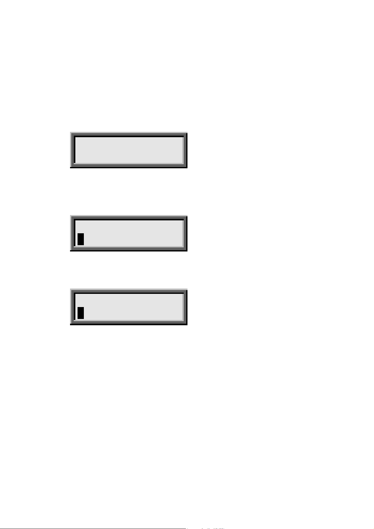
After the device performed cold start datum and time will be displayed:
14-1
Date
Time
With key + resp.
done by pressing key C (devices with numerical keyboard) resp.
alphanumerical keyboard). After entering date/time a password map be entered.
ww tt.mm.jj
hh:mm:ss
ENTER
datum/time can be overtaken. Changing date/time can be
(devices with
CLR
Set Password
_______________
Entry is optional an may be stepped over with + resp.
must be confirmed :
ENTER
. An entered password
Confirm Password
_______________
After confirming the entered password the entry mask for data capturing will be
shown.
____________________________________________________________________aitronic
Page 57
_________________________________________________ Standard Program MTSTD
14-2
Data Capturing
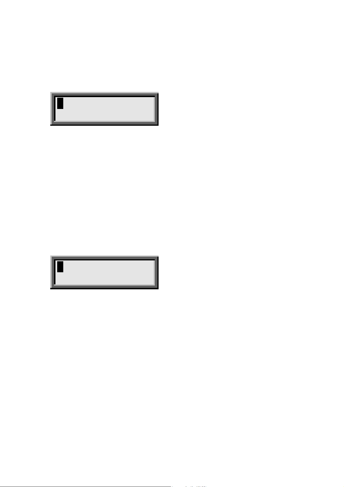
After entering date/time and password the Standard Program mask is shown.
Standard Program 2
deals to capture article numbers and quantities.
________________
_______ _______
When the cursor resides in the empty article number field an article number can be
read by pressing the trigger switch.
The scanned article number is shown on the LCD with quantity "
the last position on the LCD shows that an article number was scanned just now.
When pressing the trigger switch or any key again this symbol vanishes. The cursor
resides under the "
following entry.
The record may be stored into data memory by pressing key + or by the scanning
the next article number.
Standard Programm 2
" in the quantity field, so that this could be overwritten by the
1
deals to capture article numbers.
". The symbol ∗ at
1
________________
_______________
When the article number field ist empty an article number can be scanned.
The scanned article number will be shown on the LCD an is stored into data
memory. The article number keeps staying on the display, the cursor is switched off
and symbol ∗ at the last position on the LCD shows that an article number was
scanned just now. By pressing the trigger switch the next time the empty input mask
with the cursor at the first position is shown again.
The keys 0...9 deal for manually data entry. In case of devices with numerical
keyboard the entry of alphanumerical characters can be done by entering the
decimal ASCII Code by means of the
Menu.
SHIFT
key or with the Standard Barcode
aitronic ____________________________________________________________________
Page 58

Standard Program MTSTD__________________________________________________
14-3
Displaying Records
With the keys and
through data memory.
By holding down key
respectively to the end of data can be performed. In case of devices with
alphanumerical keyboard key
executed.
The selected record ist shown and the cursro is switched off. When the trigger
switch or any key is pressed the actual input mask is shown again..
record by record can be scanned forward and backward
SHIFT
and pressing key Taste ora jump to the beginning
or
must pressed before this function can be
Modifying/deleting/undeleting a Record
Devices with numerical Keyboard
The actual input mask must be empty for this functions. Display the record you want
to change, delete or undelete (as described in previous section). Press key
and hold it down. Press key C as often until the desired function:
"Change Record?", "Delete Record?" or "Undelete Record?" is displayed in line 2
of the LCD. Release both keys. If you now confirm with key +, the displayed function
is executed. Each other key breaks the function. Deleted records are displayed with
the symbol # at the last cursor position of the LCD.
Geräte with alphanumerical Keyboard
Press key
By pressing key + the displayed function will be performed. Each other key lead to
cancelling the function. Deleted records are shown with symbol # at the last LCD
position, in case of selected configuration parameter
instead of keys
DEL
SHFIT C
.
Show deleted Record
SHIFT
.
Function Keys
Functions are performed by holding down key
key 0 to 9.
____________________________________________________________________aitronic
SHIFT
and pressing the appropriate
Page 59

_________________________________________________ Standard Program MTSTD
14-4
Data Transmission
Data transmission can be done with MTWIN or a client specific application.
With Charging/Communication Adapter or Infrared Cradle (offline)
Connect the charging/communication adapter or the infrared cradle to the
appropriate interface (default for MTWIN is COM1) of the PC and start MTWIN on
the PC.
With RS-485 Cradle or LAP-EC (offline)
Connect the RS-485-Cradle (resp. the RS-485 network) to the appropriate interface
(COM1 or COM2) of the PC and start PRONET on the PC.
With RF Modue and LAP-EC (online)
Connect the RF base station (accesspoint) to the appropriate interface (COM1 or
COM2) of the PC and start PRONET on the PC (refer to
PRONET M
ANUAL
).
With Charging/Communication Adapter (RS-232) or Infrared Cradle
The data transmission may be performed in several ways:
• Manual data transmission with the appropriate function codes or the appropriate
menu function.
• Calling the data via the serial interface from PC program MTWIN or from a client
specific application.
• In case of configuration parameter
CTS or SIO Command
"
Ready for Data Transmission
set after switching on the terminal via interface line DTR
Start Data Transmission: PowerOn+
" will be show on the LCD.
At the beginning of data transmission "
Data Transmission active...
shown an the captured data are transmitted.The end of data transmission will be
shown with "
Data Transmission completed
" angezeigt.
If the terminal is connected to the serial interface during data capturing and therefor
switched on all the time, the captured data may be called using the appropriate SIO
command.
ATTENTION
: In case of infrared data transmission a finally error rate can’t be
prevented (below 1 promille). Therefor when using an infrared cradle the XModemprotocol
muss
be used for data transmission!
" will be
aitronic ____________________________________________________________________
Page 60

Standard Program MTSTD__________________________________________________
14-5
With RF Communication or RS-485 Network and LAP-EC
In case of active LAP-EC the captured data are first stored in data memory. The
data transmission is then performed in background to the PC. An established data
connection between terminal and PC is required. This data connection is active
when the terminal is logged in and right below on the LCD the symbol o is shown.
When using an RS-485 cradle the terminal must be put into the cradle.
After the data transmission is successful performed the data transmission lock
should be set by SIO command T1 ("
Data transmitted
condition the data memory may be cleared by SIO command
holding down key
SHIFT
and pressing key C (resp. key
" will be shown). In this
CLRMEM
in case of
DEL
or by
alphanumerical keyboard).
The transmitted data have the following format:
%%STX-
artical no.
<
artical no.
<
%%ETX-
ssssss/rrrrr/tt.mm.jjjj/hh:mm:ss
M
cccc
><HT><
M
><HT><
<CR><LF>
quantity
M
quantity
><CR><LF>
M
M
><CR><LF>
<CR><LF>
rrrrr
ssssss
tt.mm.jjjj
hh:mm:ss
Time of data transmission,
cccc
Amount of the following data records,
Devices serial number (refer to data plate),
Date of data transmission,
16-Bit checksum in hex format. The checksum is calculated
starting with "
%STX
" up to "
%%ETX-
" included by adding all
printable ASCII characters (hex codes $20 up to $7E included).
____________________________________________________________________aitronic
Page 61

_________________________________________________ Standard Program MTSTD
14-6
Erasing the Data Memory
To clear the data memory manually the "
Data transmitted
required. This condition is reached after a succesful data transmission and/or by
setting the data transmission lock by SIO command T1.
Devices with numerical Keyboard
By holding down key
SHIFT
and pressing key C "
Delete Data Memory?
shown. After confirming with key + data memory will be cleared. All other key will
cancel this function.
Devices with alphanumerical Keyboard
Press key
instead of key
DEL
SHIFT C
.
". Condition is
" will be
aitronic ____________________________________________________________________
Page 62

Standard Program MTSTD__________________________________________________
Test Barcodes
Code 39
14-7
*CODE-39P*
CODE-39
*01234A*
01234
__________________________________________________________________________
UPC
1<MCDEFG=hijabn>2
__________________________________________________________________________
EAN
<CDEF=ghif> 2<DEQRHT=jabcde>
__________________________________________________________________________
Code 2/5 int.
ÄNdz&ä
4567890
Ä!-8CNYdpä
01223344556677
____________________________________________________________________aitronic
Page 63

_________________________________________________ Standard Program MTSTD
14-8
Code 2/5 std.
<01236>
0123
<1234565>
123456
__________________________________________________________________________
Code 128
ÖCode-128:ä
Code-128
Öabc-ABC-123_ä
abc-ABC-123
aitronic ____________________________________________________________________
 Loading...