

Page 1

TB-01 Specification V1.0
I
TB-01 Specification
Version V1.0
Copyright ©2019
Copyright © 2019 Shenzhen Ai-Thinker Technology Co., Ltd All Rights Reserved
Page 2

TB-01 Specification V1.0
II
Disclaimer and Copyright Notice
The information in this article, including URL addresses for reference, is subject to change without notice.
This document is provided "as is" without warranty of any kind, including any warranty of merchantability,
fitness for a particular purpose, or non-infringement, and any warranty of any proposal, specification, or
sample mentioned elsewhere. No liability is assumed in this document, including any infringement of any
patent rights arising out of the use of the information in this document. No license is granted by estoppel or
otherwise in this document, either express or implied.
The test data obtained in this article are all obtained from the testing performed by Anxinke Labs. Actual
results may vary slightly.
The Bluetooth Alliance member logo is owned by the Bluetooth Alliance.
All trademark names, trademarks and registered trademarks mentioned in this article are the property of
their respective owners and are hereby declared.
The final interpretation right belongs to Shenzhen Anxinke Technology Co., Ltd.
Pay attention
The contents of this manual may be changed due to product version upgrades or other reasons. Shenzhen
Anxinke Technology Co., Ltd. reserves the right to modify the contents of this manual without any notice or
prompt. This manual is only used as a guide. Shenzhen Anxin Ke Technology Co., Ltd. makes every effort to
provide accurate information in this manual, but Shenzhen An Xin Ke Technology Co., Ltd. does not ensure
that the content of the manual is completely error-free. All statements and information in this manual And
recommendations do not constitute any express or implied warranty.
FCC WARNING STATEMENT
Changes or modifications not expressly approved by the party responsible for compliance could void the
user’s authority to operate the equipment. This equipment has been tested and found to comply with the
limits for a Class B digital device, pursuant to Part 15 of the FCC Rules. These limits are designed to provide
reasonable protection against harmful interference in a residential installation. This equipment generates
uses and can radiate radio frequency energy and, if not installed and used in accordance with the
instructions, may cause harmful interference to radio communications. However, there is no guarantee
that interference will not occur in a particular installation. If this equipment does cause harmful
interference to radio or television reception, which can be determined by turning the equipment off and
on, the user is encouraged to try to correct the interference by one or more of the following measures: -Reorient or relocate the receiving antenna.
-- Increase the separation between the equipment and receiver.
-- Connect the equipment into an outlet on a circuit different from
that to which the receiver is connected.
-- Consult the dealer or an experienced radio/TV technician for help.
This device complies with Part 15 of the FCC Rules. Operation is subject to the following two conditions:
(1) This device may not cause harmful interference, and
(2) This device must accept any interference received, including interference that may cause
undesired operation.
Copyright © 2019 Shenzhen Ai-Thinker Technology Co., Ltd All Rights Reserved
Page 3
TB-01 Specification V1.0
III
Version
Date
Revised content
Maker
Approve
V1.0
2019.11.25
First developed
Yiji Xie
Document development/revision/revocation resume
Copyright © 2019 Shenzhen Ai-Thinker Technology Co., Ltd All Rights Reserved
Page 4

IV
CONTENT
TB-01 Specification V1.0
一、 INTRODUCTION
二、 SPECIFICATION
三、 DIMENSION
.............................................................................................
四、PIN DEFINITION
五、SCHEMATIC
六、DESIGN GUIDE
...............................................................................................
...........................................................................................
七、REFLOW PROFILE
八、PACKAGING
九、CONTACT US
...............................................................................................
.............................................................................................
.......................................................................................
........................................................................................
错误!未定义书签。
错误!未定义书签。
错误!未定义书签。
..................................................................................................................
错误!未定义书签。
错误!未定义书签。
...............................................................................................................
错误!未定义书签。
错误!未定义书签。
VIII
XIII
Copyright © 2019 Shenzhen Ai-Thinker Technology Co., Ltd All Rights Reserved
Page 5

TB-01 Specification V1.0
Copyright © 2019 Shenzhen Ai-Thinker Technology Co., Ltd All Rights Reserved
V
1.INTRODUCTION
The TB-01 intelligent lighting module is a Bluetooth module based on the EP2S12F40 chip
and compatible with BT 4.2 low-power Tmall Genie Mesh. This module supports the Bluetooth
module directly controlled by Tmall Genie and has a Bluetooth mesh networking function.
Peer-to-peer network communication, using Bluetooth broadcast for communication, can
ensure timely response in the case of multiple devices. It is mainly used in intelligent light
control, which can meet the requirements of low power consumption, low latency, and
short-range wireless data communication.
Features
Can be directly controlled by Tmall Elf without a gateway
2.0mm pitch pin vertical solder package
2 positive white warm white PWM outputs
With on-board antenna, no need to design antenna
Brightness (duty cycle) adjustment range 5% -100%
Factory default 50% duty cycle for cool and warm colors
PWM output power 1KHz
With night light function
With wall switch to switch color temperature function
Page 6
Copyright © 2019 Shenzhen Ai-Thinker Technology Co., Ltd All Rights Reserved
VI
LIST 1 Main Parameters
Model Name
TB-01
Size
22.0*14.0*2.0(±0.2)MM
Wireless Standard
Bluetooth V4.2
Frequency Range
2400 ~ 2483.5MHz
Output Power
10dBm
Max Sensitivity
-92dBm
Interface
PWM
Work Temperature
-20℃ ~ 70 ℃
Store Temperature
-40 ℃ ~ 125 ℃ , < 90%RH
Voltage Range
Voltage 2.7V ~ 3.6V, Current≥50mA
Power
Deep Sleep Mode:0.9uA
Sleep Mode:1.9uA
Mesh Mode:30mA
Transmission
distance
80m ~ 150m
TB-01 Specification V1.0
Page 7
TB-01 Specification V1.0
Copyright © 2019 Shenzhen Ai-Thinker Technology Co., Ltd All Rights Reserved
VII
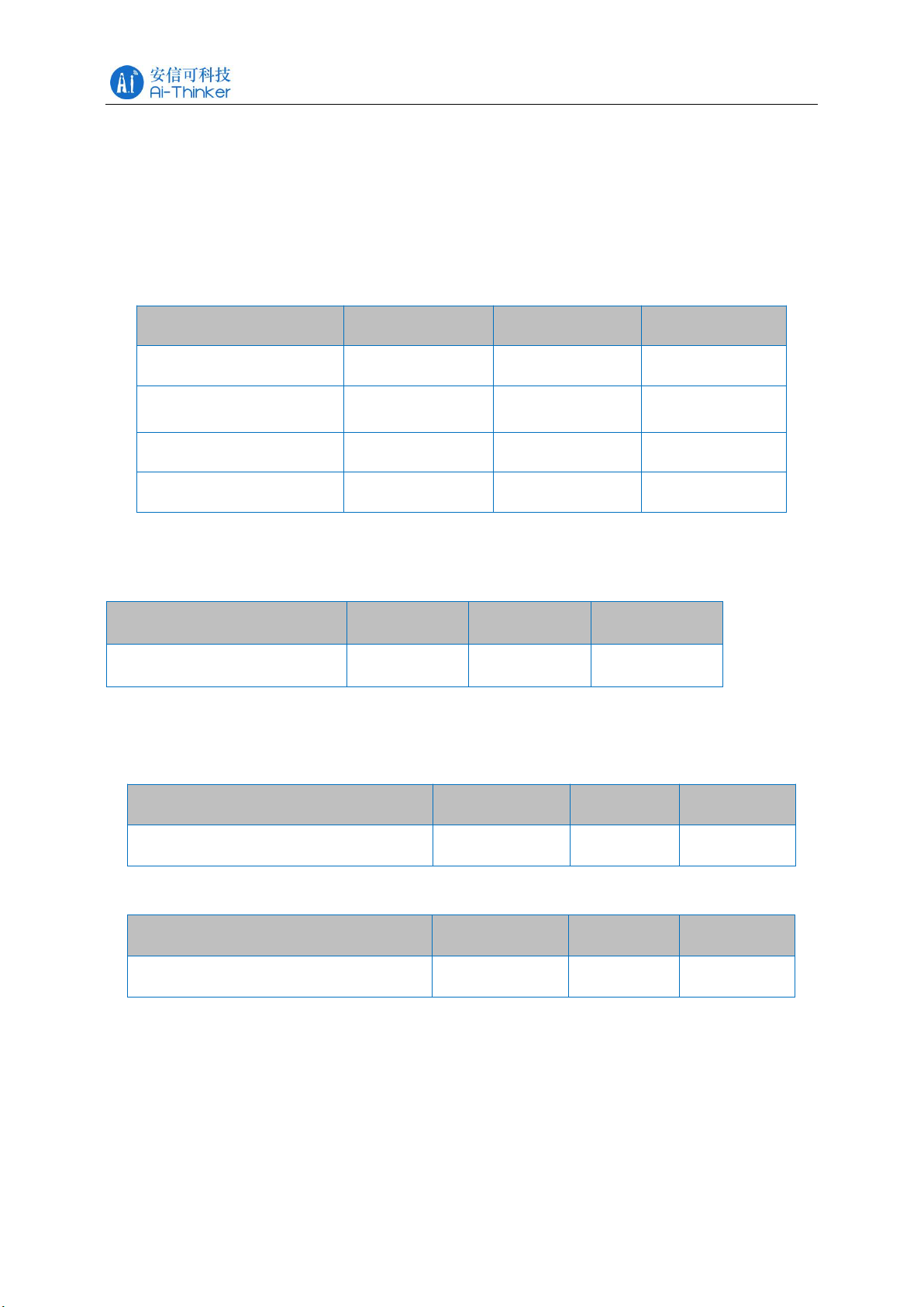
Item
Min
Typical
Max
RF Voltage(VCCRF)
-
1.2V
-
Item
Min
Typical
Max
Average Power
8.5dBm
9.5dBm
10dBm
Item
Min
Typical
Max
Sensitivity
-92dBm
-91dBm
-90dBm
Item
Min
Typical
Max
Voltage
2.7V
3.3V
3.6V
I/O Voltage (VCCIO)
-0.3V
-
3.6V
Work Temperature
-20℃
-
+70℃
Store Temperature
-40℃
-
+125℃
2.SPECIFICATION
Electrical characteristics
Absolute Maximum Rating
Any exceeding the following absolute maximum ratings may cause damage to AB1611
Recommended Operating Conditions
RF Specification
Output Power
Sensitivity
Page 8

Copyright © 2019 Shenzhen Ai-Thinker Technology Co., Ltd All Rights Reserved
VIII
3.DIMENSION
TB-01 Specification V1.0
Page 9

TB-01 Specification V1.0
Copyright © 2019 Shenzhen Ai-Thinker Technology Co., Ltd All Rights Reserved
IX
No.
Item
Function Description
1
GND
Ground
2
3V3
Electricity supply
3
PB1
Positive white PWM output, high effective
4
PB0
Warm white PWM output, high effective
5
PC5
AC power-down detection pin (function can be customized)
6
GND
Ground
7
GND
Ground
4.PIN DEFINITION
The TB-01 module has a total of 7 interfaces. For example, the pin diagram, the pin function
definition table is the interface definition.
TB-01 Pin diagram
PIN function definition sheet
Page 10

Copyright © 2019 Shenzhen Ai-Thinker Technology Co., Ltd All Rights Reserved
X
5.SCHEMATIC
TB-01 Specification V1.0
6.DESIGN GUIDE
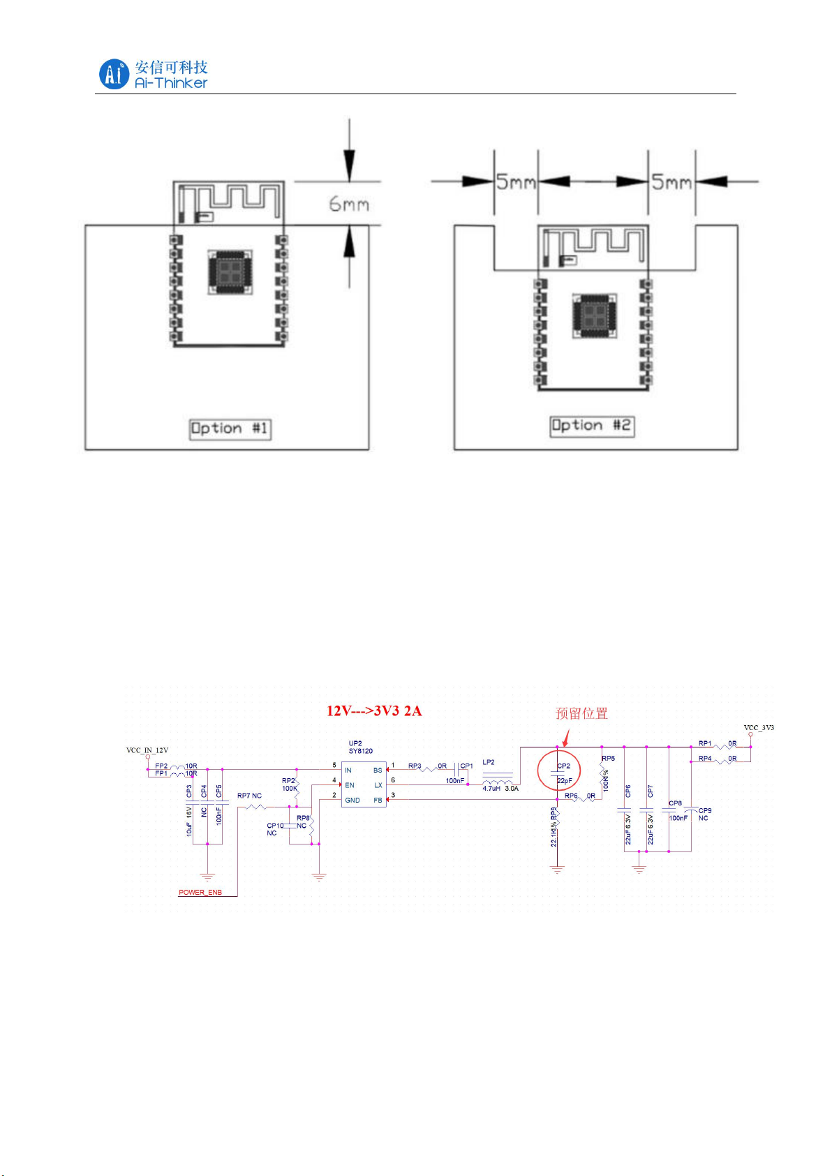
1、Application circuit
2、Antenna layout requirements
(1) For the installation position on the motherboard, the following two methods are recommended:
Solution 1: Place the module on the edge of the motherboard, and the antenna area extends beyond the
edge of the motherboard.
Solution 2: Place the module on the edge of the motherboard, and the edge of the motherboard hollows
out an area at the antenna position.
(2) In order to meet the performance of the on-board antenna, it is forbidden to place metal parts around
the antenna and keep it away from high-frequency devices.
Page 11
TB-01 Specification V1.0
Copyright © 2019 Shenzhen Ai-Thinker Technology Co., Ltd All Rights Reserved
XI
3、Electricity Supply
(1) Recommended 3.3V voltage, peak current above 50mA
(2) It is recommended to use LDO power supply; if using DC-DC, it is recommended to
control the ripple within 30mV.
(3) The DC-DC power supply circuit is recommended to reserve the position of the
dynamic response capacitor, which can optimize the output ripple when the load changes
greatly.
(4) 3.3V power interface is recommended to add ESD
devices.
4、PWM Dimming Solution Design Instructions
For lamps that require dimming, you only need to connect the PWM pins of the
corresponding color to the control end of the subsequent stage drive circuit; the PWM
independently outputs a 100-level adjustable digital signal, and the subsequent stage circuit
can be voltage The driving type may be a current driving type.
Page 12

TB-01 Specification V1.0
Copyright © 2019 Shenzhen Ai-Thinker Technology Co., Ltd All Rights Reserved
XII
Connection diagram
5、LED Drive Reference Design
TB-01 module application only needs 3.3V power supply and simple driving circuit to
achieve intelligent light control. Take MOS tube to drive a channel of white light as an
example, the design reference is as follows; CW_I is the module's positive white light PWM
output , Q1 is MOS tube, WW is LED lamp beads, the other 4 road lamp driving circuit is the
same as this road design method.
6、Secondary development
The TB-01 module supports users to write their own firmware programs to achieve
customized functions.
If you use a Linux machine to develop the firmware, you can refer to the SDK,
documentation and source address of Anxin's collation:
https://github.com/Ai-Thinker-Open/Telink_825X_SDK.
If you use Windows development, you can refer to the original SDK provided by the chip
manufacturer. Download address:
http://wiki.telink-semi.cn
Page 13

Copyright © 2019 Shenzhen Ai-Thinker Technology Co., Ltd All Rights Reserved
XIII
7.REFLOW PROFILE
TB-01 Specification V1.0
Page 14

Copyright © 2019 Shenzhen Ai-Thinker Technology Co., Ltd All Rights Reserved
XIV
8.PACKAGING
As shown below, the packaging of TB-01 is taping packaging.
TB-01 Specification V1.0
9.CONTACT US
Company Website:https://www.ai-thinker.com
Development DOCS:http://docs.aithinker.com
Official Forum:http://bbs.ai-thinker.com
Sample Purchase:https://anxinke.taobao.com
Business:sales@aithinker.com
Technical Support:support@aithinker.com
Company Address:410, Building C, Gufeng Huafeng Smart Innovation Port, Xixiang, Baoan District,
Shenzhen
Tel:0755-29162996
Page 15

If the FCC identification number is not visible when the module is installed inside another device, then
the outside of the device into which the module is installed must also display a label referring to the
enclosed module. This exterior label can use wording such as the following: “Contains Transmitter
Module FCC ID: 2AHMR-TB-01 Or Contains FCC ID: 2AHMR-TB-01”
When the module is installed inside another device, the user manual of this device must contain below
warning statements:
1.This device complies with Part 15 of the FCC Rules. Operation is subject to the following two
conditions:
(1) This device may not cause harmful interference, and
(2) This device must accept any interference received, including interference that may cause undesired
operation.
2.Changes or modifications not expressly approved by the party responsible for compliance could void
the user's authority to operate the equipment.
The devices must be installed and used in strict accordance with the manufacturer's instructions as
described in the user documentation that comes with the product. The host product manufacturer is
responsible for compliance to any other FCC rules that apply to the host not covered by the modular
transmitter grant of certification. The final host product still requires Part 15 Subpart B compliance
testing with the modular transmitter installed. The end user manual shall include all required regulatory
information/warning as shown in this manual.
 Loading...