

AIS AI2524 User Manual

TM
AISwitch
AI2524 Router
User’s Manual
August 1997
Applied Innovation Inc.

AI2524 Router
User’s Manual
TM
AISwitch

Applied Innovation Inc.
AI2524 Router
User’s Manual
August 1997
Reference 2524UM

AI2524 Router User’s Manual
Copyright Notice
Copyright © 1983-1997 by Applied Innovation Incorporated (AII). The material discussed in
this manual is the proprietary property of AII. AII retains a l l righ ts to reprodu ction and distribution
of this document.
AISwitch, AISwitch Series 180, and AISwitch Series 130 are registered trademarks of AII.
UNIX is a registered trademark in the United States and other countries, licensed exclusively
through X/Open Company Limited. Any other trademarks appearing in this manual are registered
trademarks of their respective comp anies.
FCC Warning
The Federal Communications Commission has set limits for emitted radio interference. The
AISwitch is constructed with this electromagnetic interference (EMI) limitation in mind. Th
AISwitch is classified under FCC regulations as a Class A device, that is, a device for use in commercial environments a nd not in residentia l areas. This devi ce has been tested and shown to comply
with the following FCC rule: Part 15 Subpart J. Operation of this equipment in a residenti al are
may cause inte rferenc e to radio and TV reception, requiring the user to take wh atev er ste ps are necessary to cor re c t the interference.
Information is availabl e from the FCC describing possible corrective actions. For lower EMI
levels, we suggest using only metal connectors and shielded cables grounded to the frame.
Electrostatic Discharge Warning
Warning: The AISwitch and its peripherals contain electrostatic sensitive components. Proper
handling, shipping, and storage precautions must be exercised:
z Removal and installation of circuit boards must be performed in a static-free en-
vironment. Tthe tec hn ician sho uld we a r an anti-static wrist strap and stand on
an anti-static mat. Both the wrist strap and mat must be grounded at the same
point as the AISwitch enclosure.
z When not in use, circuit boards must be kept in their anti-static plastic bags.
z Circuit boards must only be removed from their anti-static plastic bags immedi-
ately prior to in stallation into the AISwitch enclosure.
z Immediately upon removal from the enc losure, circuit boards must be inserted
into their anti-static bags.
z Do not ship or store t he electronic circuit boards near strong electrostatic, elec-
tromagnetic , magnetic, or radi oactive fields.
Specifications are subject to change without notice.
Applied Innovation Inc.
5800 Innovation Driv
Dublin, Oh io 43016-3271
614-798-2000
800-247-9482
FAX: 614-798-1770
August 1997
2524UM

AI2524 Router Card User’s Manual
Contents
Chapter 1: Introduction ..............................................................................................1-1
Documen tation Ov erview .................. ...... ...... ...... ...... ...... ...... ...... ...... ........ ...... .............1-1
Related D o cu mentation......... .. .. .. .. .. .. .. .. .. .. .. .. .. .. .. .. .. .. .. .. .. .. .. .. .. .. .. .. .. .. .. .. .. .. .. .. .. .. ............1-3
Contact Info rmation .................... ...... ........ ...... ........ ...... ........ ........ ...... ........ ...... ............ 1 -4
Text Co n ve ntions. .. .. .. .. .. .. .. .. .. .. .. .. .. .. .. .. .. .. .. .. .. .. .. .. .. .. .. .. .. .. .. .. .. .. .. .. .. .. .. .. .. .. .. .. .. .. .............1-5
Chapter 2: AI2524 Overview......................................................................................2-1
Introduction..................................................................................... ..............................2-1
T1 CSU/DSU...................................................................................................2-1
Four Wires 5 6K CSU /DSU.......... .. .. .. .. .. .. .. .. .. .. .. .. .. .. .. .. .. .. .. .. .. .. .. .. .. .. .. .. .. ..........2-1
5-IN-1 S eri al Cable Interface... .. .. .. .. .. .. .. .. .. .. .. .. .. .. .. .. .. .. .. .. .. .. .. .. .. .. .. .. .. .. .. .........2-1
Software Features and Functions ..................................................................................2-2
Scalability ........................................................................................................2-2
Reliable, Ad a pti ve Routing.... .... .. .... .. .... .. .... .. .... .... .. .... .. .... .. .... .. .... .. .... ............2 -2
Remote Access and Protocol Translation ........................................................2-2
Managem en t and Security.. .. .. .. .. .. .. .. .. .. .. .. .. .. .. .. .. .. .. .. .. .. .. .. .. .. .. .. .. .. .. .. .. .. .. ..........2-5
Software Specifications.................................................................................................2-5
Supported M edia ....... .. .. .. .. .. .. .. .. .. .. .. .. .. .. .. .. .. .. .. .. .. .. .. .. .. .. .. .. .. .. .. .. .. .. .. .. .. .. ...........2-5
Supporte d N et w ork Protocols......... .. .. .. .. .. .. .. .. .. .. .. .. .. .. .. .. .. .. .. .. .. .. .. .. .. .. .. .. .........2-5
Connections..... .. .. .. .. .. .. .. .. .. .. .. .. .. .. .. .. .. .. .. .. .. .. .. .. .. .. .. .. .. .. .. .. .. .. .. .. .. .. .. .. .. .. .. .. .. .. .. .. ..............2-7
External Connection Requirements ..... .. .. .. .. .. .. .. .. .. .. .. .. .. .. .. .. .. .. .. .. .. .. .. .. .. .. ........2-7
Chapter 3: Configuration Overview..........................................................................3-1
Introduction...................................................................................................................3-1
Boot Rou te r for F irst T ime......... .... .... .... .... .... .... .... .... .... .... .... .... .... .... .... .... .... .... ...........3-1
Configure the Router.....................................................................................................3-2
Using Configu ration Mo d ............ ...... .... .... ...... .... ...... .... ...... .... ...... .... ............3-2
Show Con figu ration .... .... .... .... .... .... .... .... .... .... .... .... .... .... .... .... .... .... .... .... .... .... ..............3-3
Save the Configuration..................................................................................................3-4
Configuration Overviews............... .. .. .. .. .. .. .. .. .. .... .. .. .. .. .. .. .. .. .. .. .... .. .. .. .. .. .. .. .. .. .. .............3-4
Use Configuration Builder...............................................................................3-4
Use the Command Interpreter..........................................................................3-4
Use the Web Browser Interface.......................................................................3-6
Configuration Storage and Hot Swap ...........................................................................3-6
Always Modify the Configuration Using Menu 4.18 ......................................3-6
Store the Configuration on the AI198 Card.....................................................3-6
Chapter 4: Understanding the User Interface ..........................................................4-1
Introduction..................................................................................... ..............................4-1
Comman d L i ne Interface ....... .. .. .. .. .. .. .. .. .. .. .. .. .. .. .. .. .. .. .. .. .. .. .. .. .. .. .. .. .. .. .. .. .. .. .. .. .. .. ...........4-1
End a Session ................................................................................................................4-2
User Interface Task List................................................................................................4-2
August 1997 TOC-1
2524UM

AI2524 Router Card User’s Manual
Comman d Modes ..... .... .... .... .... .... .... .... .... .... .... .... .... .... .... .... .... .... .... .... .... .... .... .............4-3
User EXEC Mode Commands .........................................................................4-6
Privileged EXEC Mode Commands................................................................4-7
ROM Monitor Mode Commands.....................................................................4-8
Global Config urat i on Mo de Commands. .. .... .... .... .... .... .... .... .... .... .... .... .... .......4-10
Interface Co n figuration Mode Commands ......... .. .. .. .. .. .. .. .. .. .. .. .. .. .. .. .. .. .. .. .......4-12
Subinterface Configuration Mode Commands ................................................4-14
Router Configuration Mode .............................................................................4-15
IPX-Router Configuration Mode .....................................................................4-16
Route-Map C onfigu ra t ion Mode. .... .... ...... .... .... ...... .... ...... .... ...... .... ...... ...........4 -17
Key Chai n Configuration Mode............ .. .. .. .. .. .. .. .. .. .. .. .. .. .. .. .. .. .. .. .. .. .. .. .. .. .........4 -17
Response Time Reporter Configuration Mod ................................................4-17
Access- List C onf igu ra tion Mode.... .... .... .... .... .... .... .... .... .... .... .... .... .... .... .........4-17
Context-Sensitive Help .................................................................................................4-18
Get Wor d H el p... .. .. .. .. .. .. .. .. .. .. .. .. .. .. .. .. .. .. .. .. .. .. .. .. .. .. .. .. .. .. .. .. .. .. .. .. .. .. .. .. .. ............4-19
Get Command Syntax Help............ .. .. .. .. .. .. .. .. .. .. .. .. .. .. .. .. .. .. .. .. .. .. .. .. .. .. .. .. .........4 -19
Get Help for Abbreviated Commands .............................................................4-19
Examples..........................................................................................................4-19
Check C o mmand Syntax.. .. .. .. .. .. .. .. .. .. .. .. .. .. .. .. .. .. .. .. .. .. .. .. .. .. .. .. .. .. .. .. .. .. .. .. ..........4-21
Comman d H i stor y Features ........... .. .. .. .. .. .. .. .. .. .. .. .. .. .. .. .. .. .. .. .. .. .. .. .. .. .. .. .. .. .. .. .. .. .. ...........4-23
Editing Fe atures ....... .... .... .... ...... .... .... .... .... .... .... .... .... .... .... ...... .... .... .... .... .... .... .............4-24
Edit Comma nd Lines that Wra ........... ...... ...... ........ ...... ........ ...... ........ ...........4-26
Web Browser Interfac .................................................................................................4-27
Web Browse r Inter fac e Task List.... ...... ........ ...... ........ ...... ........ ........ ...... ........4-27
Enable the Web Browser Interface..................................................................4-27
Use Compatible Hardware and Software.........................................................4-27
Access Your Router 's Home Pag ................. .. .. .. .. .. .. .. .. .. .. .. .. .. .. .. .. .. .. .. .. .. ........4-28
Issue Commands Using the Web Browser Interfac .......................................4-29
Enter Commands Using Hypertext Links........................................................4-29
Enter Commands Using the Command Field..................................................4-30
Enter Commands Using the URL Window .....................................................4-30
Chapter 5: Using AutoInstall......................................................................................5-1
Introduction........... .. .. .. .. .. .. .. .. .. .. .. .. .. .. .. .. .. .. .. .. .. .. .. .. .. .. .. .. .. .. .. .. .. .. .. .. .. .. .. .. .. .. .. .. .. ..............5-1
Preparing for AutoInstall ..............................................................................................5-1
AutoInstal l Req uir eme nts ........ .... .... .... .... .... .... .... .... .... .... .... .... .... .... .... .... .... .... .............5-2
Use a DOS-Based TFTP Server....................................................................................5-4
How AutoInstall Works................................................................................................5-5
Acquire the New Router's IP Address .............................................................5-5
Resolve the IP Address to the Host Name.......................................................5-7
Download the New Router's Host Configuration Fil .....................................5-9
Perform the AutoInstall Procedur ...............................................................................5-11
Modify the Ex ist ing Router's Co nfiguration........... .. .. .. .. .. .. .. .. .... .. .. .. .. .. .. .. .......5-11
Set Up the TFTP Server ...................................................................................5-14
Set Up the BOOTP or RARP Server ...............................................................5-16
Connect the New Router to the Network......................... .. ................ .. ............5-17
Use Setup for Configuration Changes ..........................................................................5-19
Setup Command Facility Task List..................................................................5-19
TOC-2 August 1997
2524UM

AI2524 Router Card User’s Manual
Use Setup after First-Time Startup ..................................................................5-19
Use the Streamlined Setup Facility..................................................................5-27
Chapter 6: Using the System Configuration Dialog.................................................6-1
Introduction...................................................................................................................6-1
System Configuration Dialog........... .. .. .. .. .. .. .. .. .. .. .. .. .. .. .. .. .. .. .. .. .. .. .. .. .. .. .. .. .. .. .. .. .. ...........6-1
Chapter 7: Manually Loading System Images..........................................................7-1
Introduction...................................................................................................................7-1
Image and Configuration File Load Task List..............................................................7-2
Retrieve System Images and Configuration Files.........................................................7-3
Retrieve System Images and Configuration File Task List .............................7-3
Copy System Images from a Network Server to Flash Memory.....................7-3
Copy Configuration Files from a Network Server to the Router.....................7-7
Change the Buffer Size for Loading Configuration Files................................7-8
Verify the Image in Flash Memo ry...... ...... ........ ...... ........ ...... ........ ...... ............7 -9
Display System Image and Configuration Information...................................7-9
Reexecute the Configuration Commands in Startup Configuration................7-11
Clear the Configuration Information ...............................................................7-11
Perform General Startup Tasks.....................................................................................7-12
General Startup Task List ................................................................................7-12
Enter Configuration Mode and Select a Configuration Source .......................7-12
Modify the Configuration Register Boot Field................................................7-15
Specify t h e S t art u p Configuration Fil ...... .. .. .. .. .. .. .. .. .. .. .. .. .. .. .. .. .. .. .. .. .. .. .. ........7-18
Store System Images and Configuration Files.......... .. .. .. .. .. .. .. .. .. .. .. .. .. .. .. .. .. .. .. .. .. .. ........7 -21
Store System Images and Configuration Files Task List............ .. .. .. .. .. .. .. .. .....7-21
Copy Sys tem Images from Fl a sh Memory to a Ne tw o rk Server.... .. .. .. .. .. .. .. ...7-21
Copy Configuration Files from the Router to a Network Server..................... 7-23
Perform St art up Tasks . .... .... .... .... .... .... .... .... .... .... .... .... .... .... .... .... .... .... .... .... .... ..............7-24
Startup T a sk L ist ..... .. .. .. .. .. .. .. .. .. .. .. .. .. .. .. .. .. .. .. .. .. .. .. .. .. .. .. .. .. .. .. .. .. .. .. .. .. .. .. ...........7-24
Partition Flash Memory U sing Dual Flash Bank... ........ ...... ........ ...... ...... ........7 -24
Use Flash Load Helper to Upgra de Software on Run-from-Flash Systems....7-29
Manually Load a System Image from ROM Monitor................ ...... .... ...... .... ...... .........7-35
Manually Bo ot from Flash............. ...... .... .... ...... .... .... .... ...... .... .... .... ...... ..........7-35
Manually Bo ot from a Ne two rk File.... .... .... .... ...... .... .... .... .... ...... .... .... .... ........7-36
Manually Bo ot from ROM... ...... .... .... ...... .... .... .... ...... .... .... .... ...... .... .... ............7-37
Use the System Image Instead of Reloading ...................................................7-37
Chapter 8: AI2524 Protocol Configuration Steps.....................................................8-1
Introduction...................................................................................................................8-1
Enable OSPF....................................................................................................8-2
Configure OSPF Interface Parameters.............................................................8-2
Configure OSPF over Different Physical Networks........................................8-3
Configure OSPF Area Parameters ...................................................................8-4
Configure OSPF Not So Stubby Area (NSSA ................................................8-5
Configure Rout e Summarization be tween OSPF Areas ..................................8-6
Configure Rout e Summarizat io n Whe n Redistributing Routes into OSPF.....8-6
Create Virtua l Links................ .. .. .. .. .. .. .. .. .. .. .. .. .. .. .. .. .. .. .. .. .. .. .. .. .. .. .. .. .. .. .. ...........8-7
August 1997 TOC-3
2524UM

AI2524 Router Card User’s Manual
Generate a Default Route.................................................................................8-7
Configure Looku p of DNS Names .. .. .. .. .. .. .. .. .. .. .. .. .. .. .. .. .. .. .. .. .. .. .. .. .. .. .. .. .. ........8-7
Force the Router ID Choice with a Loopback Interfac ..................................8-8
Disable Default OSPF Metric Calcula t ion Based on Bandwidth ....................8-8
Configure OSPF on Simplex Ethernet Interfaces............................................8-8
Configure Route Calculation Timers......... .. .. .. .. .. .. .. .. .. .. .. .. .. .. .. .. .. .. .. .. .. .. .. ........8 -9
Configure OSPF over On-Demand Circuits....................................................8-9
Network Illustration.........................................................................................8-10
AI2524 IG RP TCP/I P Config uration Steps .... .... .... .... .... .... .... .... .... .... .... .... .... .... ..........8-11
IGRP Update ..................................................................................................8-11
IGRP Configuration Task List.........................................................................8-11
Create the IGRP Routing Process ....................................................................8-12
Allow Point-to-Point Updates for IGRP..........................................................8-12
Define Unequal-Cost Load Balancing.............................................................8-12
Control Traffic Distribution.............................................................................8-13
Adjust the IGRP Metric Weights .....................................................................8-13
Disable Holddo wn ................. ................ ................ ................ ..........................8-14
Enforce a Maximum Network Diamete ..........................................................8-14
Validate Sourc e IP Addresses......... .... .... .... .... .... .... .... .... .... .... .... .... .... .... .........8-15
Network Illustration.........................................................................................8-15
AI2524 RIP TCP/IP Configuration...............................................................................8-16
RIP Configuration Task List............................................................................8-16
Enable RIP.......................................................................................................8-16
Allow Point-to-Point Updates for RI .............................................................8-16
Specify a RIP Version......................................................................................8-17
Enable RIP Authentication..............................................................................8-18
Disable Route Summarization .........................................................................8-18
Run IGRP and RI P Concur re ntly .... .... ...... .... .... ...... .... .... .... ...... .... .... .... ...........8-19
Disable the Validation of Source IP Addresses...............................................8-19
Chapter 9: AI2524 OSI/CLNP Configuration Steps................................................9-1
Introduction..................................................................................... ..............................9-1
ISO CLNS Configuration Task List..............................................................................9-1
Understand Addresses...................................................................................................9-2
ISO IGRP NSAP Address................................................................................9-3
IS-IS NSAP Address........................................................................................9-4
Addressing Rules .............................................................................................9-5
Addressing Examples.......................................................................................9-6
Routing Table Example . ..................................................................................9-6
Understand Routing Processes.............. .. .. .. .. .. .. .. .. .. .. .. .. .. .. .. .. .. .. .. .. .. .. .. .. .. .. .. .. .. .. .. ..........9 -8
Dynamic Routing.............................................................................................9-8
Intermediate Systems (IS) and End Systems (ES)...........................................9-8
Static Routing...................................................................................................9-9
Routing Decisions............................................................................................9-9
Configure I SO IGRP Dynam ic Routing .. .. .. .. .. .. .. .. .. .. .. .. .. .. .. .. .. .. .. .. .. .. .. .. .. .. .. .. .. .. .. .........9 -10
Enable ISO IGRP.............................................................................................9-10
Example: Dynamic Routing within the Same Area.........................................9-11
Example: Dynamic Routing in More Than One Are .....................................9-12
TOC-4 August 1997
2524UM

AI2524 Router Card User’s Manual
Example: Dynamic Routing in Overlapping Areas .........................................9-13
Example: Dynamic Interdoma inRouting ........................................................9-15
Configure I SO I GR P Parameters .... .... .... .... .... .... .... .... .... .... .... .... .... .... .... .........9-17
Configure IS- IS Dyn a mic Routing ........... .... .... .... .... .... .... .... .... .... .... .... .... .... .... ............9 -19
Enable IS-IS.....................................................................................................9-19
Example s: IS-IS Routing Co n fig u ration ..... .. .. .. .. .. .. .. .. .. .. .. .. .. .. .. .. .. .. .. .. .. .. .. .......9-20
Assign Multiple Area Addresses to IS-IS Areas..............................................9-23
Example s: NETs Configuration ........ .. .. .. .. .. .. .. .. .. .. .. .. .. .. .. .. .. .. .. .. .. .. .. .. .. .. .. .........9-24
Example: Route r in Two Areas............ .. .. .. .. .. .. .. .. .. .. .. .. .. .. .. .. .. .. .. .. .. .. .. .. .. ..........9-25
Configure IS- IS Par am eters .. .... .... .... .... .... .... .... .... .... .... .... .... .... .... .... .... ...........9 -27
Configure IS-I S Int er fa ce Parameters ...... .... .... .... .... .... .... .... .... .... .... .... .... ........9-30
Configure CLNS Stat ic Routing ..... .. .. .. .. .. .. .. .. .. .. .. .. .. .. .. .. .. .. .. .. .. .. .. .. .. .. .. .. .. .. .. .. .. .. ..........9-33
Enable Static Routes ........................................................................................9-33
Example s: Basic Static R outing.. .. .. .. .. .. .. .. .. .. .. .. .. .. .. .. .. .. .. .. .. .. .. .. .. .. .. .. .. .. .. .........9-34
Example: Static Intradoma inRouting..............................................................9-36
Example: Static Interdoma inRouting..............................................................9-38
Configure Variations of the Static Route.........................................................9-41
Map NS A P Ad d resses to Media Addresses............ .. .. .. .. .. .. .. .. .. .. .. .. .. .. .. .. .. .......9-41
Configure Miscellaneous Features................................................................................9-43
Specify Shortcut NSAP Addresses..................................................................9-43
Use the IP Domain Name System to Discover ISO CLNS Addresses............9-44
Create Packet-Forwarding Filters and Establish Adjacencies .........................9-44
Example s: CLNS Filter........ .. .. .. .. .. .. .. .. .. .. .. .. .. .. .. .. .. .. .. .. .. .. .. .. .. .. .. .. .. .. .. .. .. ..........9 -45
Redistribute Routin g Infor mation....................................................................9-45
Example s: Route Map.......... .. .. .. .. .. .. .. .. .. .. .. .. .. .. .. .. .. .. .. .. .. .. .. .. .. .. .. .. .. .. .. .. .. ..........9 -48
Specify Preferred Ro utes ......... .. .. .. .. .. .. .. .. .. .. .. .. .. .. .. .. .. .. .. .. .. .. .. .. .. .. .. .. .. .. .. ..........9 -49
Configure ES-IS Hello Packet Parameters ......................................................9-49
Configure CLNS over WANs .... .. .. .. .. .. .. .. .. .. .. .. .. .. .. .. .. .. .. .. .. .. .. .. .. .. .. .. .. .. .. .. .. .. .. .. .. ...........9-51
Example: ISO CLNS over X.25.......................................................................9-51
Enhance I S O CLN S Per for mance..... .... .... .... .... .... .... .... .... .... .... .... .... .... .... .... .... ............9-53
Specify t h e M T U Size.......... .. .. .. .. .. .. .. .. .. .. .. .. .. .. .. .. .. .. .. .. .. .. .. .. .. .. .. .. .. .. .. .. .. ..........9 -54
Disable Checksums.................... .. .............................. ................ ......................9-54
Disable Fast Swit ching Through the Cache.....................................................9-54
Set the Congestion Threshold..........................................................................9-55
Transmit Error Protocol Data Units (ERPDUs)............................................... 9 -55
Control Redirect Protocol Data Units (RDPDUs)......... .. .. .. .. .. .. .. .. .. .. .. .. .. .. ......9-55
Configure Par ameters for Loc ally Sour ced Packets . ........ ...... ........ ........ .........9 -56
Example: Performance Parameter ..................................................................9-56
Monitor and Maintain the ISO CLNS Network............................................................9-57
Configure TARP on ISO CLNS ........ ...... ........ ...... ........ ........ ...... ........ ...... ........ ............9-59
TARP Configuration Task List........................................................................9-60
Enable TARP and Configure a TARP TID......................................................9-60
Disable TARP Caching....................................................................................9-61
Disable TARP PDU Origination and Propagation...........................................9-61
Configure Multiple NSAP Addresses..............................................................9-61
Configure Stat i c T ARP Adjacency and Blacklist Adjacency..........................9-61
Determine TIDs and NSAPs............................................................................9-62
Configure TARP Timers.... .. .. .. .. .. .. .. .. .. .. .. .. .. .. .. .. .. .. .. .. .. .. .. .. .. .. .. .. .. .. .. .. .. .. ..........9-63
August 1997 TOC-5
2524UM

AI2524 Router Card User’s Manual
Configure Miscellaneous TARP PDU Information.........................................9-64
Monitor and Maintain the TARP Protocol.......................................................9 -64
Example s: T ARP Configuration... .. .. .. .. .. .. .. .. .. .. .. .. .. .. .. .. .. .. .. .. .. .. .. .. .. .. .. .. .. .........9 -65
Chapter 10: Serial Interface Configuration Steps..................................................10-1
Introduction.................................................................................................................10-1
Configure the Synchronous Serial Interfaces..............................................................10-1
Chapter 11: AI2524 Sync PPP Configuration Steps...............................................11-1
Introduction..................................................................................... ............................11-1
Configuration Overview ........ .. .. .. .. .... .. .. .. .. .. .. .. .. .. .. .... .. .. .. .. .. .. .. .. .. .. .... .. .. .. .. .. .. .. ...........11-1
PPP Configuration Task List .........................................................................11-2
Enable PPP Encapsulation ..........................................................................................11-3
Enable CH AP or PAP Authe ntication ......... .. .. .. .. .. .. .. .. .. .. .. .. .. .. .. .. .. .. .. .. .. .. .. .. .. .. .. .........11-3
Example : CHAP w i th a n Encrypted P a ssword.............. .. .. .. .. .. .. .. .. .. .. .. .. .. ......11-5
Enable Link Quality Monitoring (LQM) ....................................................................11-6
Configure Automatic Detection of Encapsulation Type.............................................11-7
Configure C o mpression of PPP Dat ..........................................................................11-7
Configure I P Add ress Pooling ............ .. .. .. .. .. .. .. .. .. .. .. .. .. .. .. .. .. .. .. .. .. .. .. .. .. .. .. .. .. .. .. ..........11-8
Peer Address Allocation ................................................................................11-8
Precede nce R ules .......... .. .. .. .. .. .. .. .. .. .. .. .. .. .. .. .. .. .. .. .. .. .. .. .. .. .. .. .. .. .. .. .. .. .. .. ...........11-9
Interface s A ffected...... ...... ...... .... ...... .... ...... .... ...... .... ...... .... ...... ...... .... ...........11-10
Choose the I P Add r ess Assignment Method .......... .. .. .. .. .. .. .. .. .. .. .. .. .. .. .. .. .......11-10
Define the Global Default Mechanism ..........................................................11-10
Configure PPP Cal lb ack .... .... .... .... .... .... .... .... .... .... .... .... .... .... .... .... .... .... .... .... ..............11-13
Configure a Rout er as a Callback Client..... .. .. .. .. .. .. .. .. .. .. .. .. .. .. .. .. .. .. .. .. .. .. .......11-14
Example: PPP Callback Client.......................................................................11-14
Configure a Rout er as a Callback Serve .......................................................11-15
Example: PPP Callback Server......................................................................11-16
Disable or
Reenable Peer Neighbor Routes .................................................................................11-17
Configure PP P Half- Bridging ........ .... .... .... .... .... .... .... .... .... .... .... .... .... .... .... .... .............11-17
Configure Multilink PPP.............................................................................................11-19
Configure Multilink PPP on Asynchronous Interfaces..................................11-19
Configure Multi link PPP o n a Single IS DN BRI Interface ........... .. .. .. .. .. .. ....1 1-20
Example : Multilink PPP on One I SDN Interfac .......... .. .. .. .. .. .. .. .. .. .. .. .. .. ......11-22
Configure Multilink PPP on Multiple ISDN BRI Interfaces.........................11-22
Example: Multilink PPP on Multiple ISDN Interfaces..................................11-25
Configure Vi rt u al Private Dial-up Networks............ .. .. .. .. .. .. .. .. .. .. .. .. .. .. .. .. .. .. .. .. .. ........11-26
Understand Virtual Private Dial-up Networks...............................................11-26
Configure Incoming VPDN Connections on the Home Gateway .................11-29
Configure Outgoing VPDN Connections on the Network Access Server.....11-29
Example: Network Access Server Servicing Multiple Domains...................11-29
Example: NAS Servicing Multiple Domains to the Same Gateway..............11-30
Example: Using TACACS+ for Forwarding from the NAS..........................11-31
Enable PPP on VTY Lines for Asynchronous Access over ISDN .............................11-32
Monitor and Maintain MLP, MMP, and VPDN Virtual Interfaces............................11-32
TOC-6 August 1997
2524UM

AI2524 Router Card User’s Manual
Chapter 12: AI2524 X.25 Configuration Steps .......................................................12-1
Introduction.................................................................................................................12-1
X.25 Conf iguration . .... .... .... .... .... .... .... .... .... .... .... .... .... .... .... .... .... .... .... .... .... .... ............12-1
X.25 Configuration Task List......... .. .. .. .. .. .. .. .. .. .. .. .. .. .. .. .. .. .. .. .. .. .. .. .. .. .. .. .........12-1
Configure Interface ............... .. .. .. .. .. .. .. .. .. .. .. .. .. .. .. .. .. .. .. .. .. .. .. .. .. .. .. .. .. .. .. .. .. .. .. .. .. ............12-2
Set the X.25 Mode .........................................................................................12-2
Set the Virtual Circuit Ranges .......................................................................12-3
Example: Virtual Circuit Ranges...................................................................12-4
Set the Packet Numbering Modulo................................................................12-5
Set the X.121 Address....................................................................................12-5
Set the Default Flow Control Values.............................................................12-6
Example: Typical X.25 Configuration...........................................................12-7
Configure Additional X.25 Interface Parameters .......................................................12-9
Configure the X.25 Level 3 Timers ...............................................................12-9
Configure X.25 Addresses .............................................................................12-10
Establish a Default Virtual Circuit Protocol..................................................12-12
Disable Packet-Level Protocol (PLP) Restarts ..............................................12-13
Configure an X.25 D atagram Transport ...... .. .. .. .. .. .. .. .. .. .. .. .. .. .. .. .. .. .. .. .. .. .. .. .. .. .. .. .........1 2-13
Configure Su bi nterfaces ............... .. .. .. .. .. .. .. .. .. .. .. .. .. .. .. .. .. .. .. .. .. .. .. .. .. .. .. .. ..........12-14
Example: Point -t o- Poin t Subinterface Configuration....................................12-16
Map Protocol Addresses to X.121 Addresses................................................12-16
Map Data gram A ddre sses t o X. 25 Hosts........ .... .... .... .... .... .... .... .... .... .... .......1 2-18
Establish an Encapsulation PVC....................................................................12-20
Example : PVC Used to Exchange IP Traffic ...... ........ ...... ........ ...... ........ .......12-21
Set X.25 TCP/I P Header Compres s ion ........ .. .. .. .. .. .. .. .. .. .. .. .. .. .. .. .. .. .. .. .. .. ........12-22
Configure X.25 Bridging ...............................................................................12-22
Configure Add it i o n al X. 25 Datagram Transport Features........ .. .. .. .. .. .. .. .. .. .. .. .. .. .. ......12-23
Configure X.25 Payload Compression .......... .... ...... .... ...... ...... .... ...... .... ........12-23
Configure the Encapsulation Virtual Circuit Idle Time.................................12-24
Increase the Number of Virtual Circuits Allowed.........................................12-25
Configure the Ignore Destination Time .........................................................12-25
Establish the Packet Acknowledgment Policy...............................................12-25
Configure X.25 User Facilities......................................................................12-26
Define the Virtual Circuit Packet Hold Queue Size ......................................12-28
Restrict Ma p Usage ... ........ ...... ...... ........ ...... ........ ...... ........ ...... ........ ...............12-28
Configure X.25 Routing..............................................................................................12-29
Enable X.25 Routing......................................................................................12-30
Example : X.25 Route Address Pattern Ma tching .......... ...... ........ ...... ............12-30
Configure a Loc al X.25 Route ........ .. .. .. .. .. .. .. .. .. .. .. .. .. .. .. .. .. .. .. .. .. .. .. .. .. .. .. .........1 2-31
Example: X.25 Routing .................................................................................12-32
Configure XOT (Remote) X.25 Rout ...........................................................12-33
Configure a Locally Switched PVC ...............................................................12-34
Example: PVC Switching on the Same Router............. .. .. .. .. .. .. .. .. .. .. .. .. .. .......12-34
Example: Simple Remote PVC Tunneling ....................................................12-35
Configure a n XOT (Remote) PVC .............. .. .. .. .. .. .. .. .. .. .. .. .. .. .. .. .. .. .. .. .. .. ........12-35
Example: Remote PVC Tunneling.................................................................12-36
Configure Additional X.25 Routing Features .............................................................12-38
Configure XOT to Use Interface Default Flow Control Values....................12-38
August 1997 TOC-7
2524UM

AI2524 Router Card User’s Manual
Substitute Addresses in a Local X.25 Rout ..................................................12-39
Configure X O T Alternate Destinations .. .. .. .. .. .. .. .. .. .. .. .. .. .. .. .. .. .. .. .. .. .. .. .. .. .......12-39
Configure C M N S Routing ......... .... .... .... .... .... .... .... .... .... .... .... .... .... .... .... .... .... .............12-40
Enable CMNS on an Interface .......................................................................12-40
Specify a CM N S Static Map of A ddr esses ....... .. .. .. .. .. .. .. .. .. .. .. .. .. .. .. .. .. .. .. .......12-41
Example: CMNS Configured for X.121 and MAC Addresses ......................12-41
Example: CMNS Switched over a PDN ........................................................12-42
Example: CMNS Switched over Leased Lines..............................................12-43
Create X.29 Access Lists............................................................................................12-45
Create an Access List.....................................................................................12-46
Example: X.29 Access List............................................................................12-46
Apply an Access List to a Line......................................................................12-47
Create an X.29 Prof ile Script... .. .. .. .. .. .. .. .. .. .. .. .. .. .. .. .. .. .. .. .. .. .. .. .. .. .. .. .. .. .. .. .. .. .. .. .. ...........12-47
Example: X.29 Profile Script.........................................................................12-47
Configure LAPB ...... .. .. .. .. .. .. .. .. .. .. .. .. .. .. .. .. .. .. .. .. .. .. .. .. .. .. .. .. .. .. .. .. .. .. .. .. .. .. .. .. .. .. .. .............12-48
Configure a L A PB Datagram Tra nsport ... .. .. .. .. .. .. .. .. .. .. .. .. .. .. .. .. .. .. .. .. .. .. .. .......12-48
Example: Typical LAPB Configuration ........................................................12-49
Modify LAP B Protocol Par ameters....... ........ ........ ...... ........ ...... ........ ............12-49
Configure LAPB Priority and Custom Queuing............................................12-52
Configure Transparent Bridging over Multiprotocol LAPB .........................12-53
Monitor and Maintain LAPB and X.25 .........................................................12-53
Example: Transpa r ent B ri dgin g for Multiprotocol LAPB Encapsulation.....12-54
Example: X.25 Configured to Allow Ping Support over Multiple Lines ......12-54
Example: Booting from a Network Server over X.25 ...................................12-56
Chapter 13: AI2524 Frame Relay Configuration Steps.........................................13-1
Introduction.................................................................................................................13-1
Frame Relay Hardware Configuration........................................................................13-1
Frame Relay Configuration Task List.........................................................................13-2
Enable Frame Relay Encapsulation on an Interface ...................................................13-2
Examples: IETF Encapsulation......................................................................13-3
Configure Dynamic or Static Address Mapping .........................................................13-3
Configure Dynamic Mapping ... .. .. .. .. .. .. .. .. .. .. .. .. .. .. .. .. .. .. .. .. .. .. .. .. .. .. .. .. .. .. .........13-3
Configure Static Mapping.. .. .. .. .. .. .. .. .. .. .. .. .. .. .. .. .. .. .. .. .. .. .. .. .. .. .. .. .. .. .. .. .. .. ..........1 3-3
Example s: Static Address Mapping........... .. .. .. .. .. .. .. .. .. .. .. .. .. .. .. .. .. .. .. .. .. .. ........13-4
Configure the LMI ......................................................................................................13-5
Allow LMI Autosense to Operate............... ................ ...................................13-5
The LMI Autosense Process ..........................................................................13-5
Configuring LMI Autosense..........................................................................13-6
Explicitly Con figure the LMI ....... ........ ...... ........ ...... ........ ...... ........ ...............13-6
Configure Fra m e Relay Swi tched Virtual Circuits.....................................................13-8
Configure S V C s on a Physical Interface .......................................................13-8
Example: SVCs on an Interfac .....................................................................13-9
Configure S V C s on a Subinterface (optional) ...............................................13-9
Example: SVCs on a Subinterface.................................................................13-10
Configure a Ma p Class... .... .... .... ...... .... .... .... .... .... .... .... .... .... .... ...... .... ............13-11
Configure a Map Group with E.164 or X.121 Addresses.................... ..........13-12
Associate th e Ma p Cl ass with Static P rotocol Add res s Maps....... .. .. .. .. .. .. ....13-12
TOC-8 August 1997
2524UM

AI2524 Router Card User’s Manual
Configure LAPF Parameters........... .. .. .. .. .. .. .. .. .. .. .. .. .. .. .. .. .. .. .. .. .. .. .. .. .. .. .. .........13-12
Configure Fra m e Relay Tr a ff ic S haping .... .... .... ...... .... .... .... .... .... .... .... .... .... .... ...........13-13
Enable Frame Relay Traffic Shaping on the Interface...................................13-14
Specify a Traffic-S h aping M ap Class f or the Interfa c .. ...... .... ...... .... ...... .....13-14
Define a Map Class with Queuing and Traffic Shaping Para meters .............13-15
Define Access Lists........................................................................................13-15
Define Priority Queue Lists for the Map Class..............................................13-15
Define Custom Queue Lists for the Map Class .............................................13-16
Example: Frame Relay Traffic Shaping ........................................................13-16
Customize Frame Relay for Your Network................................................................13-18
Configure Fra m e Relay Sub in ter faces ..... .... ...... .... .... .... .... .... .... .... .... .... ........13-18
Examples: Basic Subinterface........................................................................13-21
Example: Frame Relay Multipoint Subinterface with Dynamic Addressing 13-22
Example : IPX Ro u te s over Frame Re l ay S u b interfaces ....... .. .. .. .. .. .. .. .. .. .. .....13-24
Example: Unnumbered IP over a Point-to-Point Subinterface ......................13-25
Example: Transpa r ent B ri dging Usin g Subi nterfaces....................................13-27
Configure Fra m e Relay S wit ching......... .... .... .... .... .... .... ...... .... .... .... .... ..........13-28
Example: PVC Switching Configuration........... .. .. .. .. .. .. .. .. .. .. .. .. .. .. .. .. .. .. ........13-30
Example: Pure Frame Relay DCE .................................................................13-31
Example: Hybrid DTE/DCE PVC Switching...... .... ...... .... ...... .... .... ...... ........13-34
Example : Switch ing over an IP Tunnel .......... .. .. .. .. .. .. .. .. .. .. .. .. .. .. .. .. .. .. .. .. .......13-36
Disable or Reenable Frame Relay Inverse ARP ............................................13-38
Create a Broadcast Queue for an Interface....................................................13-38
Configure P ayload C o mpre ssion ........ .... .... .... .... .... .... .... .... .... .... ...... .... .........13-39
Configure TCP/IP Header Compression........................................................13-39
Example: IP Map with Inherited TCP/IP Header Compression ....................13-42
Example: Using an IP Map to Override TCP/IP Header Compression .........13-42
Example: Disabling Inherited TCP/IP Header Compression.........................13-43
Example: Disabling Expli cit TCP/IP Header Compression ..........................13-44
Configure Discard Eligibility.................. .............................................. .........13-45
Configure DLCI Priority Levels....................................................................13-45
Monitor the Frame Relay Connections .......................................................................13-47
Example: Config u rat ion Providing Backward Compatibility........................13-47
Example: Booting from a Network Server over Frame Relay.......................13-48
Chapter 14: T1 Interface Configuration Steps ........... ............................................14-1
Introduction..................................................................................... ............................14-1
Configure Fr act ional T1..............................................................................................14-1
Configuration Overview ............ .. .. .. .... .. .. .. .. .. .. .. .. .. .. .... .. .. .. .. .. .. .. .. .. .. .... ..........1 4-1
Specify t h e C l o ck S o u rce......... .. .. .. .. .... .. .. .. .. .. .. .. .. .. .. .... .. .. .. .. .. .. .. .. .. .. .... ..........1 4-1
Enable Data Inversion Before Transmission .................................................14-1
Specify the Frame Type of a FT/T1 Line ......................................................14-2
Specify the CSU Line Build Out ...................................................................14-2
Specify FT1/T1 Line-Code Type...................................................................14-3
Enable Remote Alarms..................................................................................14-3
Enable Loopcodes that Initiate Remote Loopbacks.......................................14-4
Specify T i meslots.......... .. .. .. .. .. .. .. .. .. .. .. .. .. .. .. .. .. .. .. .. .. .. .. .. .. .. .. .. .. .. .. .. .. .. .. ...........14-5
August 1997 TOC-9
2524UM

AI2524 Router Card User’s Manual
Chapter 15: 56/64-kbps Switched and Digital Data Services (DDS) Interface Config-
uration Steps...............................................................................................................15-1
Introduction.................................................................................................................15-1
Set the Clock Source ...................................................................................................15-1
Set the Network Line Speed........................ ................ ................ .. ................ ..............15-2
Enable Scrambled Data Coding ..................................................................................15-3
Change between DDS and Switched Dial-Up Modes................................................1 5-3
Enable Acceptance of a Remote Loopback Request ..................................................15-4
Select a Service Provider ............................................................................................15-4
Chapter 16: Basic Configuration..............................................................................16-1
Connecting to the Network .........................................................................................16-1
Connecting to an Ethernet Network...............................................................16-1
Connecting to a WAN............. .... ...... .... ...... .... ...... .... ...... .... ...... ...... .... ...........16-1
Configuring .................................................................................................................16-1
Booting the Router for the First Time............................................................16-2
Configuring the Router ...............................................................................................16-2
Using Configu ration Mo d ............ ...... .... .... ...... .... ...... .... ...... .... ...... .... ..........16-3
Using AutoIn stall.............. ...... ........ ...... ........ ...... ........ ........ ...... ........ .............16-4
Using the System Configuration Dialog........................................................16-5
Configuring the Ethernet or Token Ring Interfaces....................................................16-10
Configuring the Synchronous Serial Interfaces ..........................................................16-11
Configuring ISDN.......................................................................................................16-12
Configuring Switched 56 ............................................................................................16-14
Configuring DDS........................................................................................................16-16
Configuring the Fractional T1/T1 DSU/CSU WAN Module .....................................16-17
Specifying the Boot Method ............ .... .. .... .. .... .. .... .. .... .. .. .... .. .... .. .... .. .... .. .... .. .. ...........16-18
Checking th e Conf igur ati on Settings ..... .. .... .. .... .. .... .. .... .. .... .. .. .... .. .... .. .... .. .... .. ...........16-20
Chapter 17: Command References..........................................................................17-1
Introduction.................................................................................................................17-1
Chapter 18: System Error Messages........................................................................18-1
Introduction..................................................................................... ............................18-1
Chapter 19: Debug Command Reference................................................................19-1
Introduction..................................................................................... ............................19-1
Appendix A: Release Notes.................................. .............................................. ........A-1
New Feat ure s................ ...... ........ ...... ........ ........ ...... ........ ...... ........ ...... ........ ..................A-1
ISDN/BR I I nfe r fa ce.... .... .... .... ...... .... .... .... .... .... .... .... .... .... .... ...... .... .... .... .... .... .............A-2
Configuring ISDN........................................................................................................A-3
Appendix B: Acronyms..............................................................................................B-1
TOC-10 August 1997
2524UM

Chapter 1: Introduction
Chapter 1: Introduction
Documentation Overview
This manual documents the use and operation of the AI2524 in an
AISwitch system. These topics are covered:
Chapter 1
Chapter 2
Chapter 3
Chapter 4
Introduction
This chapter provides a documentation over-
view, rel ated documentation, contact infor
mation, and text conventions.
AI2524 Overview
This chapter describes the Cisco IOS software featu res and AI252 4 hardware specifications.
Configuration Overview
This chapter describes the process of booting
the router for the first time and provides overviews of configuration methods.
Understanding the User Interfac
This chapter introduces Cisco IOS softwar
interface, and includes instructions for accessing command modes, context-sensitiv
help, and command history and editing features.
Chapter 5
Chapter 6
Chapter 7
August 1997 Page 1-1
2524UM
Using AutoIn stall
This chapter describes how use AutoInstall
for automatic and dynamic configuration o
the AI2524.
Using the System Configuration Dialog
This chapter descri bes how to use the System
Configuration Dialog to manually configure
the router.
Manually Loading System Images
This chapter describes how to manually load
system images in the event that typical startup procedures malfunction.

AI2524 Router Card User’s Manual
Chapter 8
Chapter 9
Chapter 10
Chapter 11
Chapter 12
AI2524 Protocol Configuration Steps
This chapter describes how to configure th
AI2524 for OSPF TCP/IP, IGRP TCP/IP, and
RIP TCP/IP.
AI2524 OSI / CLNP Configuration Steps
This chapter describes how to configure th
AI2524 for ISO IGRP dynamic routing, IS-IS
dynamic routing, and CLNS static routing.
Serial Int erface Configura tion Steps
This chapter describes how to configure synchronous s eri al interfaces.
AI2524 Sync PPP Configuration Steps
This chapter describes how to enable PPP encapsulation and perform a variety of PPP
configuration tasks.
AI2524 X.25 Configuration Steps
This chapter describes how to configure th
X.25 interface, and includes datagram transport, routing, and X.29 access lists and profile
scripts.
Chapter 13
Chapter 14
Chapter 15
Chapter 16
Chapter 17
AI2524 Frame Relay Configuration Steps
This chapter describes how to enable frame
relay encapsulation and perform a variety of
Frame Relay configuration tasks.
T1 Inter face Configuration Steps
This chapter describes how to configure th
AI2524 for fractional T1.
56/64-kb ps Switched and Dig i tal Data Services (D DS) I nterface Config uration Steps
This chapter describes how to configure
switched and DDS interfaces.
Basic Configuration
This chapter describes the AI2524’ s panel,
cable connections, and firmware.
Comman d Refe renc es
This chapter contains a link to the AI2524/
Cisco IOS v. 11.2 documentation CD.
Page 1-2 August 1997
2524UM

Chapter 1: Introduction
Related Documentation
Chapter 18
Chapter 19
Appendix A
Appendix B
Documentation for AISwitch products includes:
AI120 Contact Alarm Monitor User’s
Manual
AISwitch 130 Hardware Manual
AI192-X User’s Manual
AI193-ES User’s Manual
AI193-TX User ’s Manual
AI194 User’s Manual
AI196-I User’s Manual
AI196-IEGB User’s Manual
AI196-X User’s Manual
AI198 Sy ste m Manag er/Us er ’s Manual
Common Alarm Panel Manual
RDC180HP Power Supply Manual
AI325AC Po wer Supply M anual
AI180FRF AICool Fan Manual
AISwitch 180 Hardware Manual
AppliedView Network Management Sys-
tem User’s Manual
System Error Messages
This chapter contains a link to the AI2524/
Cisco IOS v. 11.2 documentation CD.
Debug Command Refe rence
This chapter contains a link to the AI2524/
Cisco IOS v. 11.2 documentation CD.
AISwitch Release Note
Incl u d e s the release n o t es for th i s version.
Acronyms
This appendix defines acronyms used in this
manual.
AI120UM
HM130-0194
192UM
UM193ES
193TXUM
AI94U
196IUM
196TUM
196XUM
98UM
180CAPUM
180PSUM
AI325UM
HMFRF-A
HW0593
AV201UM
To order these or any other AISwitch manuals, contact your sales representative at (8 00) 247-9482.
August 1997 Page 1-3
2524UM

AI2524 Router Card User’s Manual
Contact Information
To regist er doc umentation, contact Appl i ed Innovation Inc. at:
Applied Innovation Inc.
Publications Dept.
5800 Innovation Dr.
Dublin, OH 43216-3271
Phone (614) 798-2000
(800) 247-9482
F AX (614) 798-1770
Email aidoc@aiinet.com
Register your documentation by completing the registration form.
The most current version of release notes and the
Manual
http://www.aiinet.com
Click on th e Docum e nt ation o pti on . These add itional ema il contacts
are also available:
National Sales Department sales@aiinet.com
Custom er Service Depa rt me nt cssupport@ ai in et.com
Market ing Depart ment info@aiinet.com
are available on the Applied Innovation web site at:
AI198 CLC User’s
Human Resources Department hr@aiinet.com
Technical Support Depar t ment techsupp@aiinet.com
Investment Relations invest@aiinet.com
Feedback for Engineering (R&D) feedback@aiinet.com
About SNMP snmp@aiinet.com
Webmaster webmaster@aiinet.com
Documentation Department aidoc@aiinet.com
Page 1-4 August 1997
2524UM

Chapter 1: Introduction
Text Conventions
Important conc ep ts th r ou ghout th is manual are emphasized with these
special text styles:
[Buttons] Function buttons that appear on a screen ar
shown in regular body text and enclosed in
square brackets. For example:
[Close]
[Send]
Commands
Variable
Arguments
In command lines, type text that appears in
this style exac tly as shown:
avdumpdb
BNC OFF
Press the <Ret ur n> or <Enter > ke y af ter all
commands.
Variable argum ents are text that you specify.
They are shown in italics. For example:
avaccess
switch_name
In this case, “switch_name” is variable text.
To enter the command, type
avaccess
and then the ac tual name of the switch.
... Ellipses (...) signify that the preceding argu-
ment can be repeated a number of times. For
example:
c
at
filename...
means that you would typ
by one or more filenames.
cat
followed
August 1997 Page 1-5
2524UM

AI2524 Router Card User’s Manual
[Optional
Arguments]
{argument|
argument}
Some arguments are optional. This means
that you have the choice of including them or
not. Optiona l arguments are s hown enclosed
in squar e brac ke t s, w hi ch are no t enter ed.
For example:
avrestore [
mea ns that you type
avrest or e
and (if you need to include a directory) type
the actual path name.
CFGMSG n, [DEFAULT]
means that you type
message number, a comma, and (optionally)
the word
Arguments between braces are grouped into
one unit. The vertica l bar signifi es th at either
the first or second argument can be used. The
braces and vertical bar are not entered. For
example:
DEFAULT
direct ory
CFGMSG
without brackets.
]
followed by
ls {
file
|
direct or y
means that you would type
either a file or a directory name.
<Keys> Keyboard controls are shown in this style.
Angle brackets dep ict keys that do not appear on the screen when pressed, such as the
<tab> or <return> keys. Keys used in combination are connected with a dash. For example, to enter:
<ALT-SysRq>
hold down the Alt key while y ou press th
SysRq ke y.
ls
}
followed by
Page 1-6 August 1997
2524UM

Chapter 1: Introduction
Labels
Menu | Submenu
Screen outpu t
Labels are used in diagrams to designat
physical components such as jumper s traps,
switches, and cable connectors. For example:
COM1
BOOT1
If the physical compo nent being described is
part of the text, it appears as regular type:
To reset the COM1 port connector, press th
BOOT switch.
Menu selections are shown in bold text. The
bar separates the main menu from submenus.
For example:
File | Exit
indicates t ha t you should sele ct the File
menu, and then select the Exit menu item.
Screen shots, system prompts, and error
messages displayed on the screen are shown
in this style:
Warning:
+CONFIG POR T,LPORT=40,H PORT=47, BITS=8
+CONFIG POR T,LPORT=48,H PORT=49, BITS=7
+CONFIG POR T,LPORT=50,B ITS=8$07 78
Warning messages indicate critical information required for your safe ty or for correct
system operation. For example:
Warning : Failure to h ee d t his i m portant
text could cause damage or unreliable results.
August 1997 Page 1-7
2524UM

AI2524 Router Card User’s Manual
Page 1-8 August 1997
2524UM

Chapter 2: AI2524 Overview
Chapter 2: AI2524 Overview
Introduction
This chapter describes the Cisco IOS software features and the AI2524
hardware specifications. The AI2524 multi-protocol router adds the
Cisco Internetworking Operating System (IOSTM) routing software to
the NEBS compliant AISwitch 180 Series. The AI2524 adds leading
edge routing capabilities through TCP/IP and OSI networks to the AI
180 Switch protocol conversion and data port concentration capabilities.
The AI2524 is designed for reliable connectivity to a Wide-Area Network (WAN). It can provide WAN/DCN connections to centralized
operations support sys t ems from central office based LAN/LCN or
X.25 networks.
The AI2524 has one Ethernet LAN interface with both a backplane
(IRB) port and a 10B a se T p o rt on t he fr ont pa nel. The backplane port
provides connections to a large number of interfaces and protocols
through a variety of AISwitch interface modules.
The base module accepts two serial interface modules in any combination. The three available modules are:
T1 CSU/DSU
The AI2524-T1 module is an integrated CSU/DSU that supports full
or fractiona l T 1 l ea se d lin e services. I t may be remote l y managed
using Simple Network Management Protocol (SNMP)
Four Wires 56K CSU/DSU
The AI2524-4W56 module is an integrated CSU/DSU that supports
4-wire 56k leased line or switched services. It may be remotely managed using Simple Network Management Protocol (SNMP)
5-IN-1 Serial Cable Interface
The AI2524-5N1 module provides a cable interface to a synchronous
serial line. I t support s full and half duplex operations up to 2.048 MHz,
full duplex. Dependent upon the interface, DTE/DCE and NRZ/NRZ1
operations are available. Ca b les are avail able for the these i nte rfaces:
August 1997 Page 2-1
AI2524UM

AI2524 Router Card User’s Manual
RS-232 DTE or DCE, EIA-530 DTE, RS-44 9 DTE or DCE , OR V.35,
DTE or DCE, up to E1 speeds.
Software Features and Functions
The AI 2524 incorpo rates Cisco IOS software. Thi s software provides:
Scalability
z
Reliable, Ad a pti ve Routing
z
Remote Access and Protocol Translation
z
Management and Security
z
Scalability
The Cisco IOS software uses scalable routing protocols to avoid needless congestion, overcome inherent protocol limitations, and bypass
many of the obstacles that result from the complex scope and geographical d i spe r s ion o f a n internetwork.
The Cisco IOS software eliminates the need for static routes and reduces network costs by efficiently using network bandwidth and resources. Advanced features such as route filtering, protocol
termination and translation, smart broadcasts, and helper address services combine to create a flexibl e, scalable infrastruc ture that can keep
pace with evo l ving network requirements.
Reliable, Adaptive Routing
The AI2524 Cisco IO S so ft w are id en t if ie s the best netw ork paths and
routes traffic around network failures. Policy-based features such as
route filtering and route redistribution save network resources by preventing data from being broad cast to nodes that do not need it. Priority
output queuing and custom queuing grant priority to important sessions when network bandwidth is scarce. Load balancing uses every
available path across the internetwork to preserve bandwidth and improve network performan ce. The Cisco IOS software al so provides the
most effective and efficient scaling av ail a ble f or ne tw ork applications
that require transparent or source- ro ut e bridging algorithms.
Remote Access and Protocol Translation
Your router connects terminals, modems, microcomputers, and networks over serial lines to LANs or Wide-Area Networks (WANs). It
Page 2-2 August 1997
AI2524UM

Chapter 2: AI2524 Overview
also provides network access to terminals, printers, workstations, and
other networks.
On LANs, terminal services support Transmission Control Protocol/
Internet Protocol (TCP/IP) on UNIX machines with Telnet and rlogin
connections. You can use the router to make connections between
hosts and resources running different protocols, including router and
access server connections to X.25 machines using X.25 Packet Assembler/Disassembler (PAD).
The Cisco IOS software supports three types of server operation:
Remote Node Services
Connect devices over a telephone network
Serial Line Internet Protocol (SLIP), compressed SLIP (CSLIP), Point-to-Point Protocol
(PPP), and X-Windows terminal protocol. See
Figure 2-
.
Terminal Service Connect asynchronous devices to a LAN or
WAN thro ugh ne two rk and terminal-emulation
software including Telnet and rlogin,.
Protocol Translation Services
Convert one virtual terminal protocol into
another protocol. See Figure 2-1
.
August 1997 Page 2-3
AI2524UM
AI2524 Router Card User’s Manual
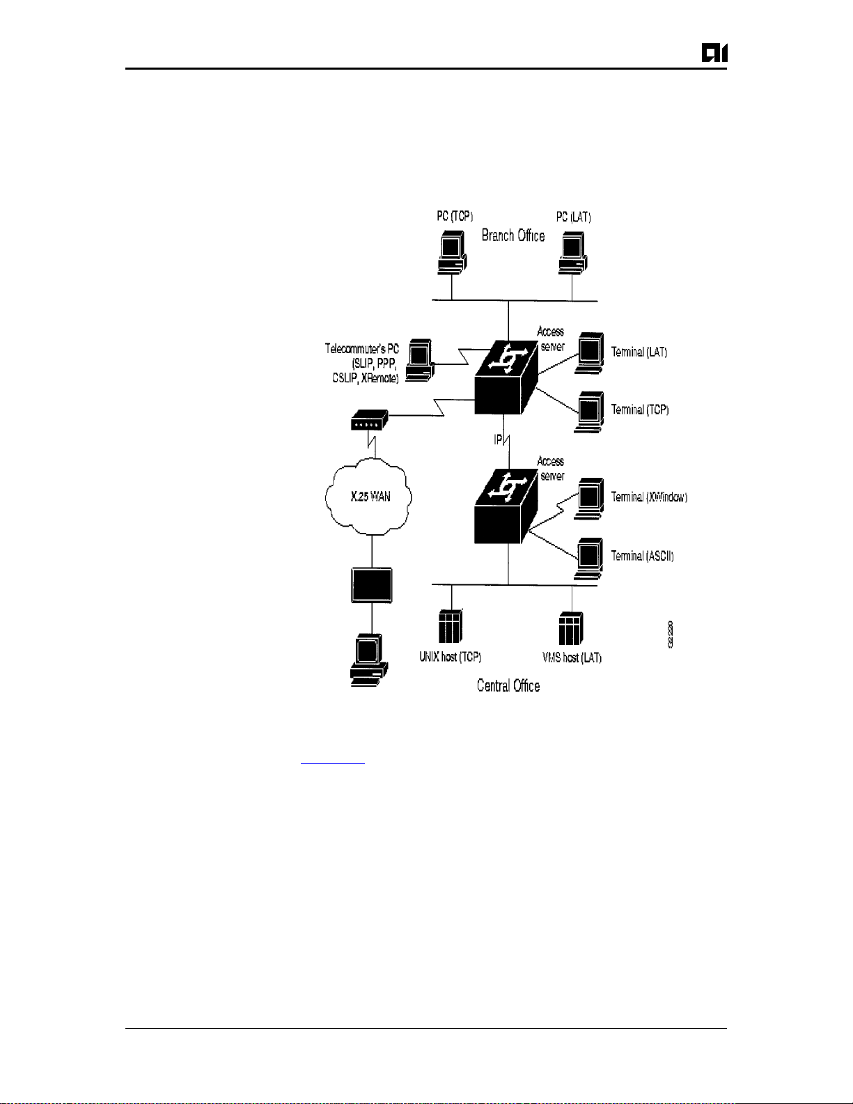
Figure 2-1:Remote Access Functionality
Figure 2-1 illustrates the functions available on access servers:
Remote node service is demons tr at ed b y th e tel ecommuter’s (re-
z
mote) PC connection running SLIP, PPP, CSLIP, or XRemote
Terminal service is shown between the terminals and hosts run
z
ning the same protocol (LAT-to-LAT or TCP-to-TCP)
Protocol translation is shown between the terminals and hosts run-
z
ning unlike protocols (LAT-to-TCP or TCP-to-LAT)
Asynchronous IP routing is shown by the PC running SLIP or
z
PPP, and b et ween the two ac cess servers.
Page 2-4 August 1997
AI2524UM

Chapter 2: AI2524 Overview
Management and Security
The Cisco IOS software provides an array of network management
and security capabilities. Integrated management simplifies administrative procedures and shortens the time required to diagnose and fix
problems. Automated operations reduce hands-on tasks and make it
possible to manage larg e, geographically dispers ed internetworks with
a small staff of experts located at a central site.
The Ci sc o IOS so ftw are p rov ides several management features including configuration services, which lower the cost of installing, upgrading, reconfiguring ro uters , an d reconfiguring access se rvers , as well as
comprehensive monitoring and diagnostic services. In addition, the
Cisco IOS software provides information and services for router management applications.
Management services are matched by their security capabilities. Th
Cisco IOS software includes a diverse tool kit for partitioning resources and prohibiti ng access to sens itive or confident ial infor mation
and processes. Multidimensional filters prevent users from knowing
that othe r users or resources are on the network. Encrypted passwo rds,
dial-in authentication, multilevel configuration permissions, network
data encryption, and accounting and logging features provide protection from and informa tion about unauthorized ac ce ss at temp ts and data
eavesdropping attemp t s .
Software Specifications
Supported Media
The AI2524 supports these industry-standard networking media:
Channelized T1
z
Ethernet: IEEE 802.3 and Type I
z
Fiber Distributed Data Inter f ac e (FDDI ) : sin gl e and dual mode
z
High-Speed Serial Interface (HSSI): supports T1
z
Synchronous serial: V.35, RS-232, RS-449, and RS-530
z
Supported Network Protocols
The Cisco IOS software supports many networking protocols, as well
as their associated routing protocols. These protocols are based on
both ope n s ta nda r ds and proprietary protocol s from a vari ety of vendors.
The Cisco IOS software can receive and forward packets concurrently
from any of t he se combinations:
August 1997 Page 2-5
AI2524UM

AI2524 Router Card User’s Manual
WAN protocols
Frame Relay
z
High-Level Data Link Control (HDLC)
z
PPP
z
X.25 a
z
Network protocols
IP
z
OSI Connectionless Network Services (CLNS) and Connection
z
Mode Network Services (CMNS)
IP Routing Protocols
The Cisco IOS software supports IP routing protocols, including interior gateway protocols and exterior gateway protocols.
Interior Gateway Protocols
Internet Gateway Routing Protocol (IGRP)
z
Enhanced IGRP
z
Open Shortest Path First (OSPF)
z
Routing Information Protocol (RIP) and RIP Version 2
z
Intermediate System-to-Intermediate System (IS-IS
z
Exterior Gateway Protocols
Exterior Gateway Protocol (EGP)
z
Router Discovery Protocols
z
ICMP Router Discovery Protocol (IRDP)
z
Hot Standby Router Protocol (HSRP)
z
Page 2-6 August 1997
AI2524UM

Chapter 2: AI2524 Overview
Connections
External Connection Requirements
The AI2524 provides LAN and WAN access in a modular router platform. The router includes an Ethernet (AUI or 10BaseT) LAN connection, and accommodates two synchronous serial modules.
The synchronous serial WAN m od ules include these external connectors:
Four-wire 56/64-kbps DSU/CSU WAN module with an RJ-48S
z
connector
Fractiona l T1/T1 DSU/CSU WAN modul e with an RJ-48C con-
z
nector
Five-in-one s ynchrono us serial WAN module with a DB-6 0 serial
z
connector. The five-in-one synchronous serial interface supports
the following signaling standards: EIA/TIA-232, EIA/TIA-449,
V.35, X.2 1, a nd EIA-530
August 1997 Page 2-7
AI2524UM

AI2524 Router Card User’s Manual
Page 2-8 August 1997
AI2524UM
 Loading...