

Airzone AZVAFDAMPER, AZVAF5OUTPUTS, AZVAFBLUEFACEC, AZVAFTHINKC, AZVAFTHINKR Installation Manual
...Page 1

rebmuNegaPdraobpilC
Installation´s Manual
Page 2

Page 3

3
TABLE OF CONTENTS
Precautions and Environmental Policy ...............................................................................................................................................................................6
Precautions ...............................................................................................................................................................................................................................6
Environmental policy ...........................................................................................................................................................................................................6
System Elements ..........................................................................................................................................................................................................................7
Control Board (AZVAFRxxxx) .............................................................................................................................................................................................7
Wired/Wireless intelligent round damper (AZVAFDAMPERXX [C/R]) ...............................................................................................................7
Wired/Wireless only radiant zone module (AZVAFZMRAD [C/R]) ......................................................................................................................7
Wired/Wireless zone module with XXX communication (AZVAFZMXXX [C/R]) ...........................................................................................8
Relay radiant heat control module (AZVAF5OUTPUTS) .........................................................................................................................................8
Blueface principal controller (AZVAFBLUEFACEC) ....................................................................................................................................................8
Wired/Wireless Think controller (AZVAFTHINK [C/R]) .............................................................................................................................................9
Wired/Wireless Lite controller (AZVAFLITE [C/R]) .....................................................................................................................................................9
Communication gateway (AZVAFGTXXX) ...................................................................................................................................................................9
0-10 V Fancoil control gateway (AZVAFGTF10) ...................................................................................................................................................... 10
5-Relay Fancoil control gateway (AZVAFGTF5R) .................................................................................................................................................... 10
Webserver Airzone cloud Ethernet/WiFi (AZVAFWSCLOUD [C/R]) ................................................................................................................. 10
Bacnet integration gateway (AZVAFBACNETG) ...................................................................................................................................................... 11
10 KOHM NTC thermistor (AZVAF10KPROBE) ......................................................................................................................................................... 11
Additional 12 V power supply (AZVAFPOWER) ....................................................................................................................................................... 11
General requirements ............................................................................................................................................................................................................. 12
Introduction ................................................................................................................................................................................................................................ 13
System installation ................................................................................................................................................................................................................... 13
Assembly and connection ..................................................................................................................................................................................................... 15
Control Board (AZVAFRxxxx) .......................................................................................................................................................................................... 15
Assembly .......................................................................................................................................................................................................................... 15
Connection ...................................................................................................................................................................................................................... 15
Wired/Wireless intelligent round damper (AZVAFDAMPERXX [C/R]) ............................................................................................................ 18
Connection ...................................................................................................................................................................................................................... 18
Flow regulation .............................................................................................................................................................................................................. 19
Wired/Wireless only radiant zone module (AZVAFZMRAD [C/R]) ................................................................................................................... 20
Assembly .......................................................................................................................................................................................................................... 20
Connection ...................................................................................................................................................................................................................... 20
Wired/Wireless zone module with XXX communication (AZVAFZMXXX [C/R]) ........................................................................................ 21
Assembly .......................................................................................................................................................................................................................... 21
Connection ...................................................................................................................................................................................................................... 22
Relay radiant heat control module (AZVAF5OUTPUTS) ...................................................................................................................................... 23
Assembly .......................................................................................................................................................................................................................... 23
Connection ...................................................................................................................................................................................................................... 24
Wired thermostats (AZVAFBLUEFACEC / AZVAFTHINKC / AZVAFLITEC) ...................................................................................................... 24
Assembly .......................................................................................................................................................................................................................... 24
Connection ..................................................................................................................................................................................................................... 25
Wireless thermostats (AZVAFTHINKR / AZVAFLITER)............................................................................................................................................ 25
Assembly .......................................................................................................................................................................................................................... 25
Changing batteries ....................................................................................................................................................................................................... 25
Page 4

4
0-10 V Fancoil control gateway (AZVAFGTF10) ...................................................................................................................................................... 26
Assembly .......................................................................................................................................................................................................................... 26
Connection ...................................................................................................................................................................................................................... 27
5-Relay Fancoil control gateway (AZVAFGTF5R) .................................................................................................................................................... 28
Assembly .......................................................................................................................................................................................................................... 28
Connection ...................................................................................................................................................................................................................... 28
Ethernet/WiFi cloud Webserver (AZVAFWSCLOUD [C/R]) .................................................................................................................................. 30
Assembly .......................................................................................................................................................................................................................... 30
Connection ...................................................................................................................................................................................................................... 30
Configuration ................................................................................................................................................................................................................. 31
BACnet integration gateway (AZVAFBACNETG) ..................................................................................................................................................... 31
Assembly .......................................................................................................................................................................................................................... 31
Configuration ................................................................................................................................................................................................................. 31
Assembly and connection evaluation .............................................................................................................................................................................. 32
Secondary zones settings ...................................................................................................................................................................................................... 32
Initial Setup ................................................................................................................................................................................................................................. 32
Blueface and Think thermostats ................................................................................................................................................................................... 32
Lite thermostats .................................................................................................................................................................................................................. 35
Lite thermostat reset ................................................................................................................................................................................................... 36
Initital configuration evaluation ......................................................................................................................................................................................... 36
User and zone settings ........................................................................................................................................................................................................... 37
Blueface Thermostat .......................................................................................................................................................................................................... 37
User Settings ................................................................................................................................................................................................................... 37
Zone Settings ................................................................................................................................................................................................................. 37
Think Thermostat ................................................................................................................................................................................................................ 38
Setting Parameters ....................................................................................................................................................................................................... 38
Advanced settings .................................................................................................................................................................................................................... 41
Advanced settings Blueface thermostat ................................................................................................................................................................ 41
System settings .............................................................................................................................................................................................................. 41
Zone settings .................................................................................................................................................................................................................. 43
Advanced settings Think thermostat ...................................................................................................................................................................... 44
Self-diagnose .............................................................................................................................................................................................................................. 45
Control board (AZVAFRxxxx) .......................................................................................................................................................................................... 45
Wired/Wireless intelligent round damper and wired/wireless only radiant zone module (AZVAFDAMPERXXX [C/R] and
AZVAFZMRAD [C/R]) .......................................................................................................................................................................................................... 46
Wired/Wireless zone module with XXX communication (AZVAFZMXXX [C/R]) ........................................................................................ 46
Relay radiant heat control module (AZVAF5OUTPUTS) ...................................................................................................................................... 47
Blueface and think thermostats (AZVAFBLUEFACEC / AZVAFTHINK [C/R]) ................................................................................................. 48
Blueface and Think Thermostat Warnings .......................................................................................................................................................... 48
Blueface and Think Thermostats errors ............................................................................................................................................................... 48
Lite Thermostats (AZVAFLITE [C/R]) ............................................................................................................................................................................. 55
Communication gateways (AZVAFGTXXX)............................................................................................................................................................... 58
0-10 V Fancoil controlgateway (AZVAFGTF10) ....................................................................................................................................................... 58
5-Relay Fancoil Control gateway (AZVAFGTF5R) ................................................................................................................................................... 59
Ethernet/WiFi Cloud Webserver (AZVAFWSCLOUD [C/R]) ................................................................................................................................. 59
Bacnet Integration Gateway (AZVAFBACNETG) ..................................................................................................................................................... 60
Page 5

5
Navigation Trees ....................................................................................................................................................................................................................... 61
Blueface Thermostat Navigation Tree ........................................................................................................................................................................ 61
Think Thermostat Navigation Tree .............................................................................................................................................................................. 62
Page 6
6
PRECAUTIONS AND ENVIRONMENTAL POLICY
PRECAUTIONS
For your security, and to protect the devices, follow these instructions:
• Do not manipulate the system with wet or damp hands.
• Disconnect the power supply before making any connections.
• Take care not to cause a short circuit in any of the system connections.
ENVIRONMENTAL POLICY
Do not dispose of this equipment in the household waste. Electrical and electronic
equipment contain substances that may damage the environment if they are not handled
appropriately. The symbol of a crossed-out waste bin indicates that electrical equipment
should be collected separately from other urban waste. For correct environmental
management, it must be taken to the collection centers provided for this purpose, at the end
of its useful life.
The equipment components may be recycled. Act in accordance with current regulations on
environmental protection.
If you replace it with other equipment, you must return it to the distributor or take it to a
specialized collection center.
Those breaking the law or by-laws will be subject to such fines and measures as are laid down
in environmental protection legislation.
Page 7

7
SYSTEM ELEMENTS
CONTROL BOARD (AZVAFRXXXX)
Electronic board with a communication gateway (see section
Communication Gateway
AZVAFGTxxx for more information),
which manages all wired and wireless devices in the system. Externally powered at 110 / 230 VAC. Wall mounted.
Functionalities:
• Controls the status of the thermostats (up to 10 zones).
• Controls the proportionality and the minimum air supply of the dampers.
• Control of auxiliary heat (up to two stages).
• Control gateway management.
• Communication with units of integral control of the installation.
• Communications with other external control systems through integration bus.
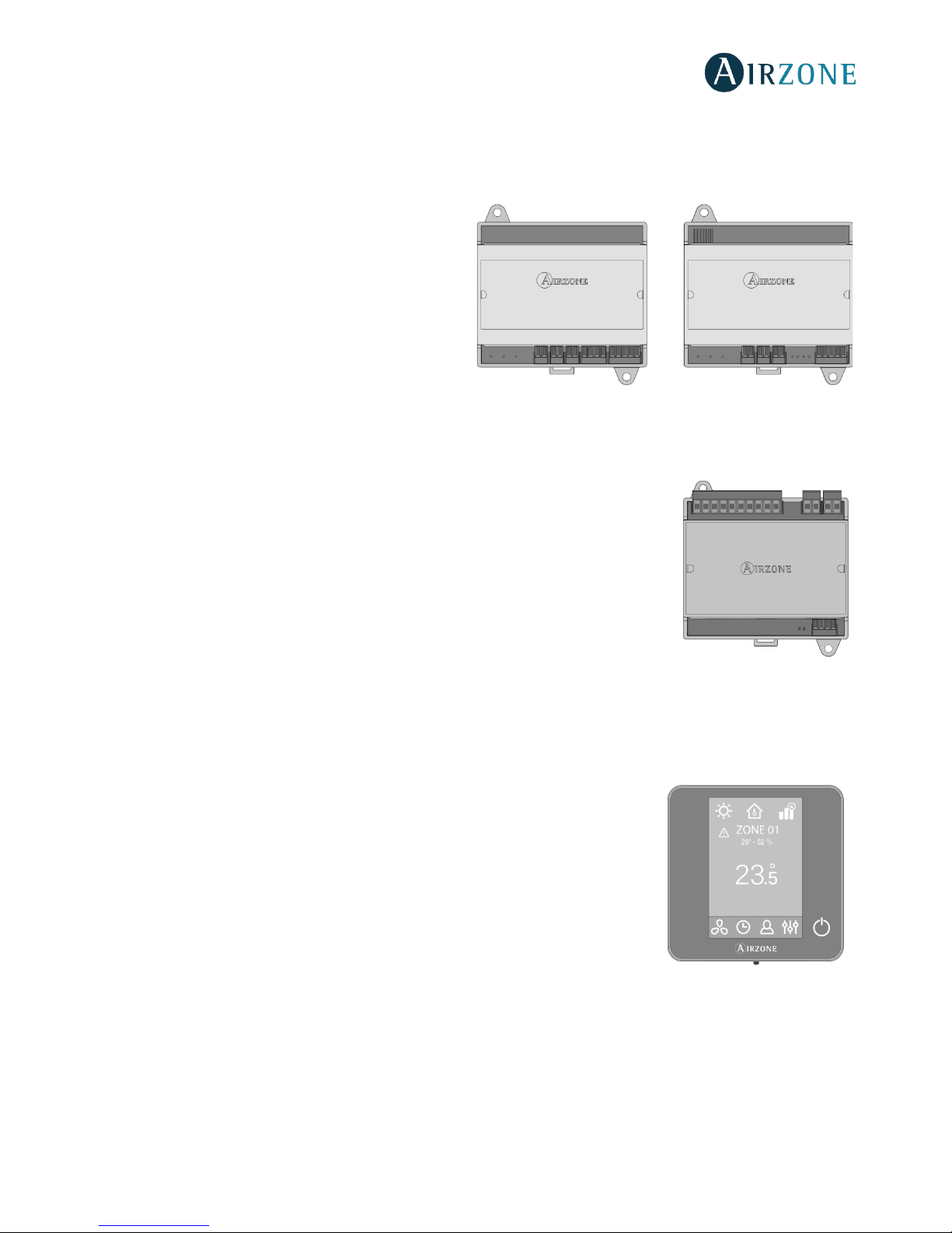
WIRED/WIRELESS INTELLIGENT ROUND DAMPER (AZVAFDAMPERXX [C/R])
Damper with actuator
Damper with actuator of 6, 8, 10, 12 or 14 inch diameter. Powered with 12 VDC by the zone module.
Zone module
Local control module for controlling damper. Wired/wireless
communication with zone thermostat. Powered through system
Airzone connection bus.
Functionalities:
• Input for detection of open windows.
• Input for detection of presence.
• Probe input.
• Remote probe function and distributed probe function.
WIRED/WIRELESS ONLY RADIANT ZONE MODULE (AZVAFZMRAD [C/R])
Local control module for controlling radiant elements.
Wired/wireless communication with zone thermostat. Powered
through system Airzone connection bus.
Functionalities:
• Input for detection of open windows.
• Input for detection of presence.
• Probe input.
• Remote probe function and distributed probe function.
AZVAFZMRADC AZVAFZMRADR
Page 8
8
WIRED/WIRELESS ZONE MODULE WITH XXX COMMUNICATION (AZVAFZMXXX [C/R])
Module for controlling direct expansion individual units through communication gateway (see section
Communication
Gateway AZVAFGTxxx
for more information). Wired/wireless communications with zone thermostat. Powered through system
Airzone connection bus. Mounted on DIN rail or on wall.
Functionalities:
• Input for detection of open windows.
• Input for detection of presence.
• Probe input.
• Remote probe function and distributed probe
function.
RELAY RADIANT HEAT CONTROL MODULE (AZVAF5OUTPUTS)
Control module of radiant heat for heating stages. Communications via Airzone connection
bus of control board. Powered by control board. Mounted on DIN rail.
Functionalities:
• Control up to 5 zones of heating elements by means of free-voltage relays.
• Demand Relay of Pump.
• Demand Relay of Boiler.
• Identified by means of a micro-switch.
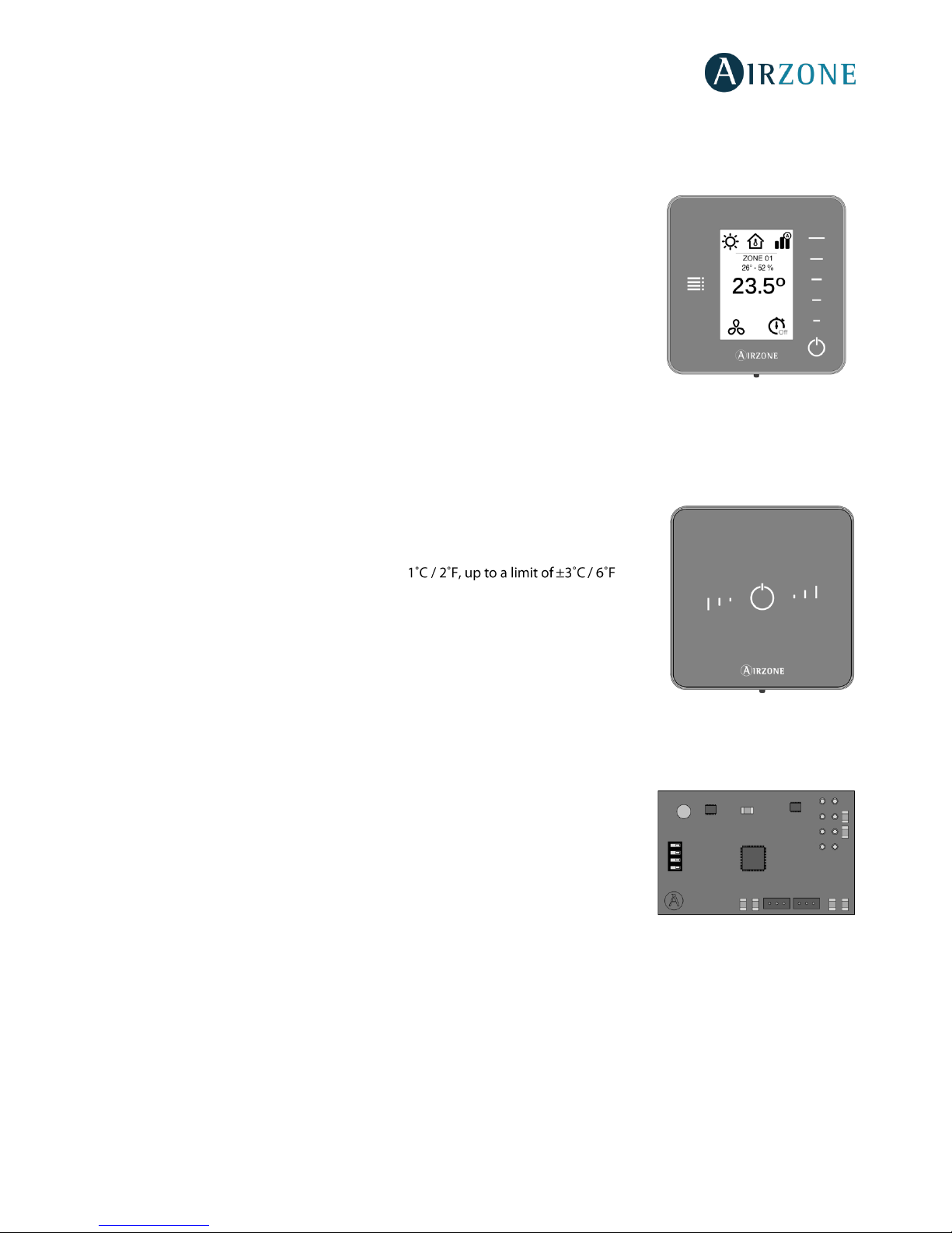
BLUEFACE PRINCIPAL CONTROLLER (AZVAFBLUEFACEC)
Color graphic interface with capacitive screen for controlling zones in Airzone systems. Powered by zone module. Finished in
steel and glass.
Functionalities:
• Available in English, French and Spanish.
• Control of temperature, operation mode (main thermostat), user mode (main
thermostat) and system speed or airflow (depends on the type of installation).
• Room temperature and relative humidity measurement of the zone.
• Configuration stages control (air, radiant or air+radiant).
• Timer function.
• Temperature, user mode and on/off time schedules.
• Remote access to other zones of the system.
• Weather forecast (optional).
AZVAFZMxxxC AZVAFZMxxxR
Page 9
9
WIRED/WIRELESS THINK CONTROLLER (AZVAFTHINK [C/R])
Graphic interface with low-energy e-ink screen and capacitive buttons for controlling zones in Airzone systems. Wired/wireless
communications. Finished in steel and glass. Powered by zone module (wired) or by battery button CR2450 (wireless).
Functionalities:
• Available in English, French and Spanish.
• Control of temperature, operation mode (main thermostat), user mode (main
thermostat) and system speed or airflow (depends on the type of installation).
• Room temperature and relative humidity measurement of the zone.
• Configuration stages control (air, radiant or air+radiant).
• Timer function.
• Weather forecast (optional).
WIRED/WIRELESS LITE CONTROLLER (AZVAFLITE [C/R])
Thermostat with capacitive buttons for controlling the temperature of the zones in Airzone systems. Wired/wireless
communication. Powered by zone module (wired) or by battery button CR2450 (wireless).
Functionalities:
• On/off of the zone.
• Set-point temperature control (accuracy: ± ).
• Room temperature and relative humidity reading.
COMMUNICATION GATEWAY (AZVAFGT XXX)
Element that integrates the functioning of the AC units and Airzone zoning systems, enhancing the performance of the
installation:
• ON/OFF depending on the number of zones in demand.
• Automatic mode changeover (Auto, Cooling, Heating or Dry) from main
thermostat.
• Automatic fan speed selection based on the number of zones on demand.
• Set-point temperature adjustment based on the set-point temperatures of the
zone thermostats of the system.
Page 10
10
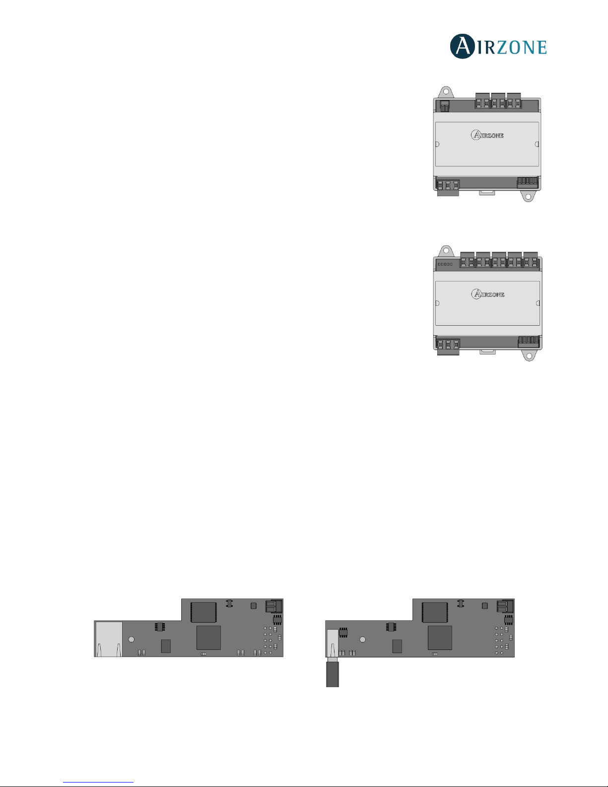
0-10 V FANCOIL CONTROL GATEWAY (AZVAFGTF10)
Control gateway of air-to-water zoning units. Fan control through 0-10 V output and openingclosing electrovalves. Compatible with 2-pipe and 4-pipe installations. Externally powered at
110/230 Vac. Mounted on DIN rail or on wall.
Functionalities:
• Two relays for electrovalve control by demand.
• 0-10 V output for fan control.
• Automatic speed control based on the zones on demand.
5-RELAY FANCOIL CONTROL GATEWAY (AZVAFGTF5R)
Control gateway for air-to-water air conditioners. Control up to three fan-speeds and the
opening and closing of valves. Compatible with 2 pipes or 4 pipes air conditioners.
Externally power supplied at 110/230. Mounted on DIN rail or on wall.
Functionalities:
• Two electro-valve control relays for demand.
• Three control relays for fan-speed selection.
• Automatic speed selection according to the number of zones on demand.
WEBSERVER AIRZONE CLOUD ETHERNET/WIFI (AZVAFWSCLOUD [C/R])
Webserver for controlling Airzone systems through Airzone Cloud platform. Accessible through browser or App (available for
IOS and Android). Connected to router via Ethernet (AZVAFWSCLOUDC) or WiFi (AZVAFWSCLOUDR). Powered through
automation bus.
Functionalities:
• Control of up to 32 systems.
• Configuration and control of zone parameters (Room and set-point temp., operating mode, etc.) and system
parameters via Airzone Cloud.
• Temperature and operating mode time schedules.
• Multi-user and multi-session.
• External control through Airzone Cloud platform.
• Remote updates of the Webserver firmware and the systems connected to it.
• Remote error detection and error resolution.
AZVAFWSCLOUDC
AZVAFWSCLOUDR
Page 11
11
BACNET INTEGRATION GATEWAY (AZVAFBACNETG)
Integration gateway for controlling Airzone installations through BACnet platform. Connected to router via Ethernet. Power
supplied through the control board automation bus.
Functionalities:
• One BACnet gateway per system.
• Status of window contact and presence contact of each zone.
• Status of the radiant stage of each zone.
• On/Off of each zone.
• Set-point temperature control of each zone.
• Operating mode status.
• State and Fancoil fan speed.
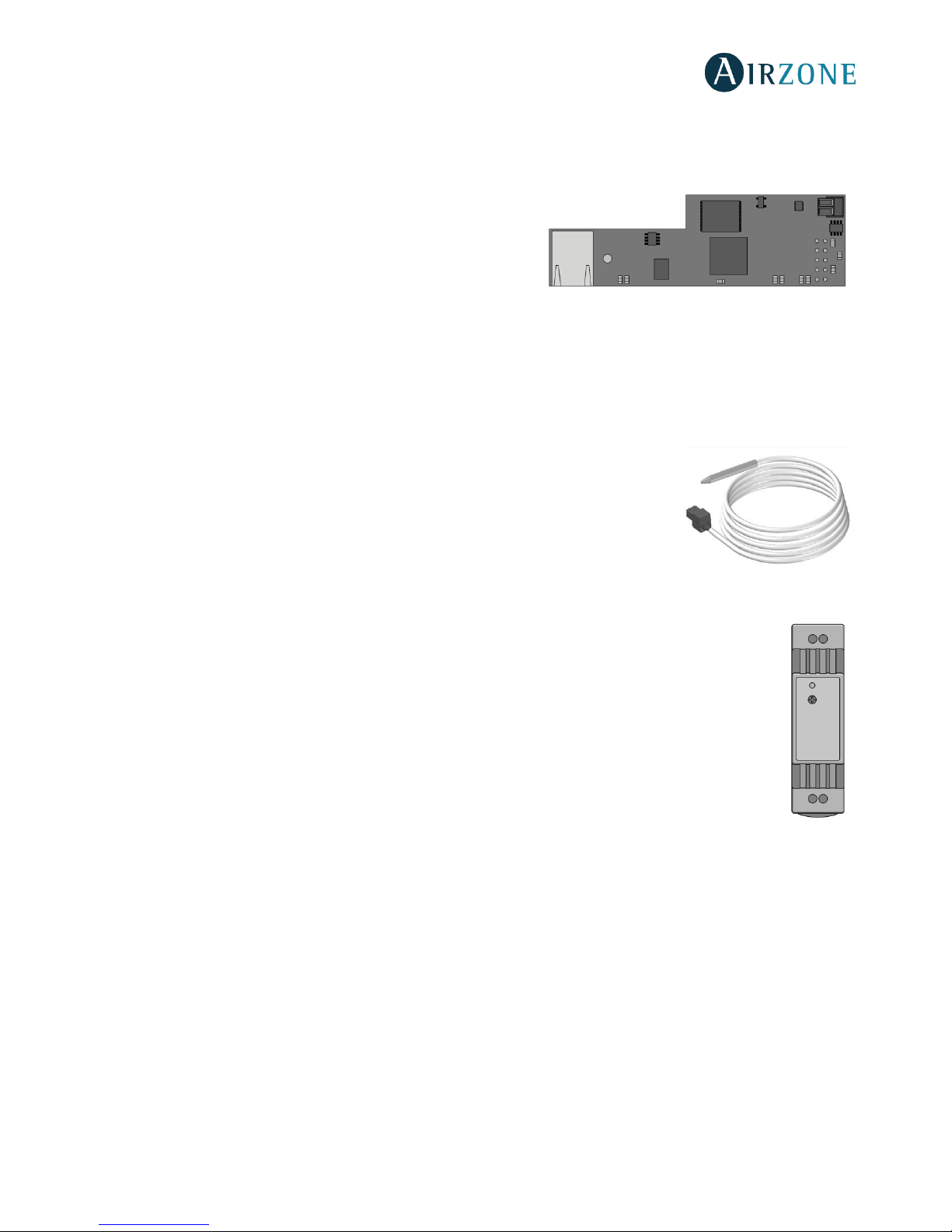
10 KOHM NTC THERMISTOR (AZVAF10KPROBE)
Temperature probe in metal sheath.
Functionalities:
• Configurable for remote or distributed sensing.
• Protection probe for air supply.
ADDITIONAL 12 V POWER SUPPLY (AZVAFPOWER)
External power supply for Airzone system. DIN rail mounted. 110/230 Vac power supply:
• Power supply for more than 6 zone modules via Blueface or 10 zone modules without Blueface. These values
can be altered depending on the separation distance among them.
Page 12
12
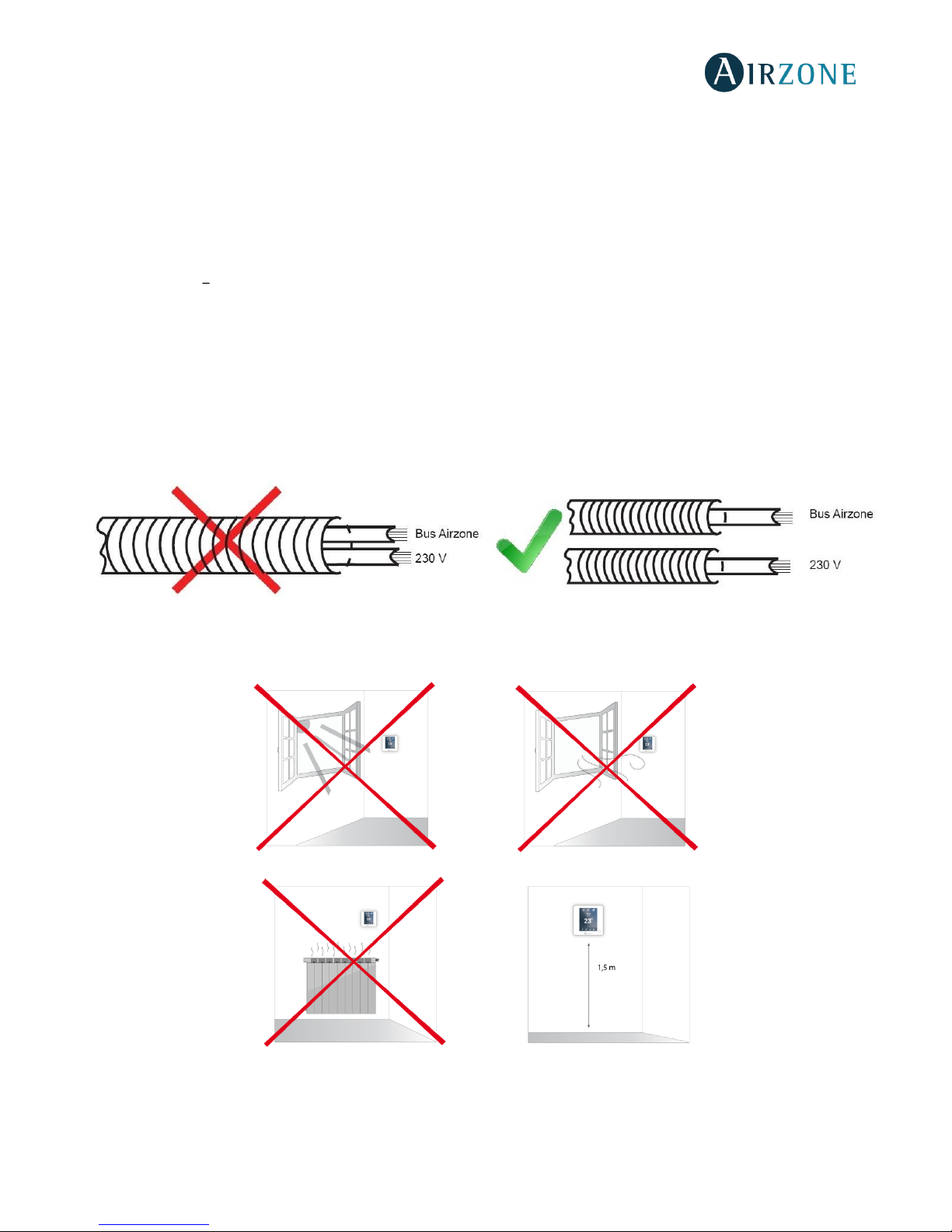
GENERAL REQUIREMENTS
Strictly follow the directions outlined in this manual:
• This system must be installed by a qualified technician.
• Make all the connections with total absence of power.
• Set and connect the elements in accordance with the electronic regulations in force.
• In order to connect the elements of the system, use the cable: shielded twisted cable formed by 4 wires
(AWG 20 4 wired).
• Do not connect the "-" pole in the "+" terminal. It may damage the device.
• For elements externally powered at 110/230 Vac, for the communications, it is only necessary to connect the poles "A"
and "B" of the bus. Connecting the "+" and " -" power poles is not recommended.
• To connect the actuators to the actuator outputs, use a 2-core section cable (0.75 mm2).
• Follow the color code for all the elements of the system.
• Do not place the system bus close to lines of force, fluorescent lights, motors, etc. It might cause interference on the
communications.
• It is recommended to label all the actuator outputs in order to facilitate their subsequent identification.
• Follow these recommendations to locate the thermostats:
Important: According to the current local and national regulations, it is mandatory to add a switch (or other element to
disconnect the system) to the external supply wiring so that a constant separation between poles is guaranteed. The system
will restart automatically if the supply is eventually turned off.
Page 13

13
INTRODUCTION
Airzone systems enable the management of Main and Zone interfaces. Main thermostats enable mode management or user
mode and fan speed of the system.
- Blueface Main: Mode, User mode icons shown in white color.
- Blueface Zone: Mode, User mode and Speed icons shown in gray color.
- Think Main: Accessing the settings menu, Operation mode and User mode are available.
- Think Zone: Accessing the settings menu, Operation mode and User mode are unavailable.
SYSTEM INSTALLATION
Before performing the Airzone system installation, check:
•
the Airzone system.
• In direct expansion unit systems, the indoor unit wired thermostat has been installed.
Important: For installations with radiant surfaces only, it is recommended the installation of buffer tanks.
In order to install properly your Airzone system, follow these steps:
Locate all the elements and perform the connection (See section
Assembly and Connection
).
- Zone and Control Modules connection with the Airzone VAF Control board. Connect the zone modules of the
system to any of the 3 Airzone connection bus terminals. Use the proper cable: shielded twisted pair 4 wired:
2x0.22 mm
2 +
2x0.5mm2 (AWG 20 4 wired). They must be connected by bus. For added security, secure the wires using
the turrets.
IMPORTANT: The maximum number of zone modules connected without their own power supply to the Airzone VAF
control Board is: 6 zone modules connected to Blueface thermostats or 10 zone modules connected to Think or Lite
thermostats. To add more zone modules, it is necessary to install the supplementary power supply unit (Airzone VAF
additional 12V power supply). Every supplementary power supply unit is enough for 6 or 10 modules as stated before.
- Connecting the thermostats. Connect each thermostat to the terminal corresponding to its zone module. Use the
proper cable: shielded twisted pair 4 wired: 2x0.22 mm
2 +
2x0.5mm2 (AWG 20 4 wired). In case of Wireless thermostat,
check it has the battery on.
- Configuration and connection of the relay radiant heat control module. If you have a relay radiant heat control
module, configure the SW2 microswitch depending on the zones to control. Once configured, perform the connection
with the radiant elements to control per each relay output of the module.
- Connection to the ducted unit (see section Gateway Connection). It is recommended to install the thermostat of the
unit. For the connection of DIN rail gateways to the control board, use the proper cable: shielded twisted pair 2 wired:
2x0.22 mm2 (AWG 24 2 wired).
- Connection of the zone modules with the elements/systems to control (Fancoil, Split, etc.). (See section zone
module connection).
Page 14
14
- Webserver Cloud connection or BACnet integration gateway. Connect your Webserver Cloud or BACnet Gateway
to the automation bus of the Control Board (follow the steps shown on the Assembly section).
All Airzone systems must be connected to internet to offer technical support.
It is only necessary to connect one Webserver Cloud per installation (control of up to 32
systems), for BACnet integration gateway, one per system.
- Auxiliary Heat and other peripherals. If your system includes auxiliary heat, connect the auxiliary heat relays of the
VAF Control board to the elements to control.
- Powering the system. Use the power input to power at 110 / 230 Vac the control board and any others control
elements that require it. To do that, use a 3x1,5 mm² cable (AWG 15 3 wired). For added security, secure the wires
using the turret.
Check all the assembly and the connection are correct (see section
Assembly and connection evaluation
).
Configure the system.
- Configure the secondary modules to associate them to a main thermostat (see section
Secondary zones settings
).
- Configure all the thermostats (see sections
Initial setup
and
Advanced settings
).
Check the correct operation of the system (See
Initial Configuration Evaluation)
.
Access all our technical documents and the self-diagnosis section, check the most FAQs,
certificates, watch our videos and read our declaration of conformity at:
myzone.airzoneusa.com
to download, complete and print the
Commissioning
document available on
myzone.airzoneusa.com to place it together with your installation.
Page 15
15
ASSEMBLY AND CONNECTION
CONTROL BOARD (AZVAFRXXXX)
Assembly
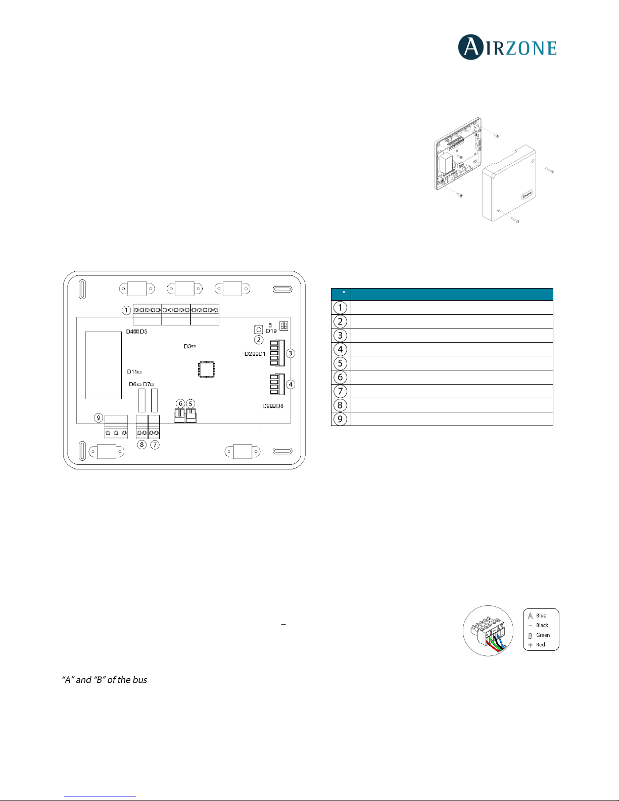
The production control board is supplied in a box to be screwed to the wall (Fig. 1). It should
be placed and mounted in accordance with the current electrotechnical regulations.
For the mounting of the control board, follow the following steps:
• Locate the control board close to the unit to be controlled.
• Unscrew the cover securing the back part to the wall.
• Make all the connections and screw the cover again.
Connection
Fig. 2
Airzone Connection Bus connectors
The Airzone Connection Bus allows you to connect all the internal components that are independent from the main board to
control up to 10 zones. These are the gateways that can be connected:
- Wired/Wireless intelligent round damper (AZVAFDAMPERxxx [C/R]).
- Wired/Wireless only radiant zone module (AZVAFZMRAD [C/R]).
- Wired/Wireless zone module with XXX communication (AZVAFZMxxx [C/R]).
- Relay radiant heat control module (AZVAF5OUTPUTS).
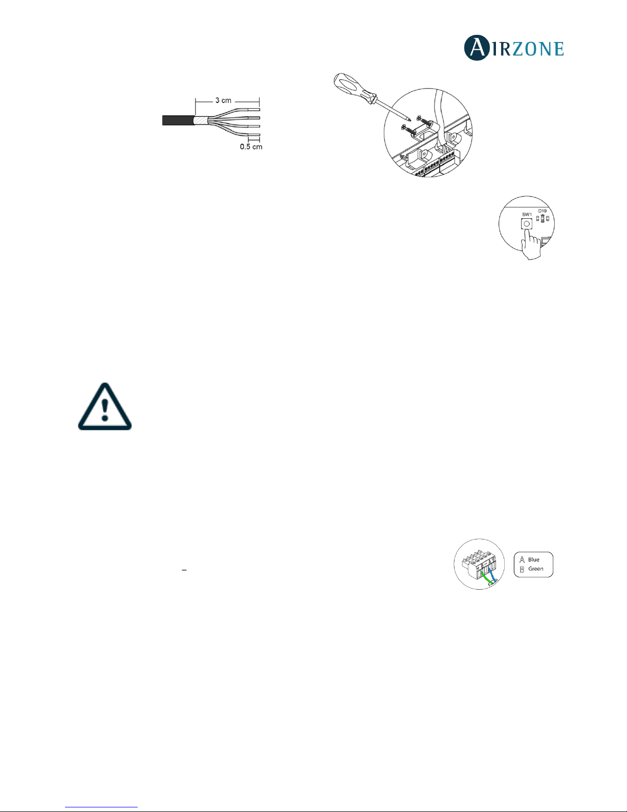
It has 3 5-pin terminals to connect the Airzone Connection Bus. Use the proper cable: shielded
twisted pair 4 wired: 2x0.22 mm
2 +
2x0.5mm2 (AWG 20 4 wired). They must be connected by
bus. Attach the wires with the terminal screws following the color code (Fig. 3). For added security,
secure the wires using the turrets (Fig. 4).
Note: For elements externally powered at 110/230 Vac, it is only necessary to connect the poles
.
N
Description
Airzone Connection Bus
SW1 Automation bus
AC unit bus
Alarm input (normally closed)
Protection temperature probe
Auxiliary heat 2nd Stage output
Auxiliary heat 1st Stage output
Power supply
Fig. 3
Fig. 1
Page 16
16
SW1
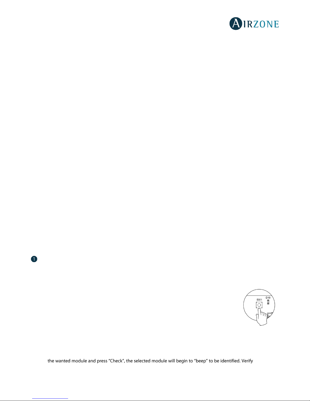
The control board can also connect to Airzone wireless elements. These elements are associated by
opening the wireless association module of the Control board. Press on SW1 and wait for the LED 19 to
remain red (Fig. 5). The wireless association module will be open for 15 minutes.
System reset: If you want to return to factory values, press and hold on SW1 (Fig. 5) until LED D19 stops
blinking. Wait 60 seconds until the system restarts before connecting again.
Automation bus connector
The automation bus allows you to interconnect multiple systems in order to control them through Airzone control peripherals
or to integrate them into a superior control network. The elements to connect to this bus are:
- Ethernet/WiFi Cloud Webserver (AZVAFWSCLOUD [C/R]).
- BACnet Integration Gateway (AZVAFBACNETG).
All Airzone systems must be connected to internet to offer technical support.
It is only necessary to connect one Webserver Cloud per installation (control of up to 32 systems), for
BACnet integration gateway, one per system.
AC unit bus connector
The AC unit bus allows you to connect different control gateway to the AC unit. The elements to connect are:
- Communication gateways (AZVAFGT xxx).
- 0-10 V Fancoil control gateway (AZVAFGTF10).
- 5 relays Fancoil control gateway (AZVAFGTF5R).
It has a 4-pin terminal to connect the AC unit bus. Use the proper cable: shielded twisted pair
2 wired: 2x0.22 mm2 (AWG 24 2 wired). They must be point-to-point connected. Attach the
wires with the terminal screws following the color code (Fig. 6).
Alarm input
This input closes all the dampers and imposes Stop mode when there is an alert. This input is configured as normally closed.
For proper operation of the system, this contact is supplied with a bonding jumper.
Fig. 4
Fig. 5
Fig. 6
Page 17
17
Protection temperature probe connector
It measures the outdoor temperature through an external probe. We recommend the use of this probe when using
electromechanical units or NON-Inverter units (when it is necessary to control the return temperature of the units).
Auxiliary heat outputs
The system includes auxiliary heat, connect the auxiliary heat relays of the VAF Control board to the elements to control. Control
relay specs are I
max
: from 1 A to 24-48 V, voltage-free. To control elements of a greater power, it is recommended to use
contactors in accordance with the power required.
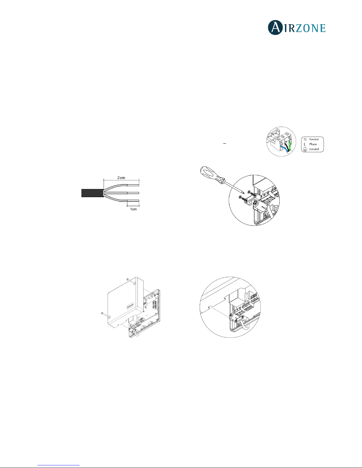
Power supply connector
This connector powers the control board and all the elements connected to it. Externally powered
at 110/230 Vac. It is connected through a 3-pin terminal. Use a 3x1,5 mm² (AWG 15 3 wired) cable.
Attach the wires with the terminal screws following the color code (Fig. 7). For added security,
secure the wires using the turret (Fig. 8).
Fig.8
Important: According to the current local and national regulations, it is mandatory to add a switch (or other element to
disconnect the system) to the external supply wiring so that a constant separation between poles is guaranteed. The system
will restart automatically if the supply is eventually turned off.
Remember: Once all the connections are made, make sure you replace the cover properly (Fig. 9).
Fig. 9
Fig. 7
Page 18
18
WIRED/WIRELESS INTELLIGENT ROUND DAMPER (AZVAFDAMPERXX [C/R])
Connection
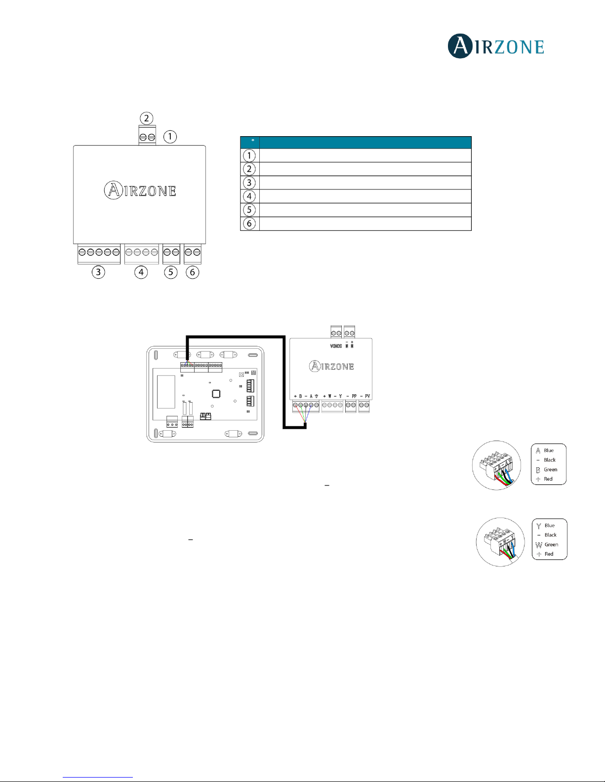
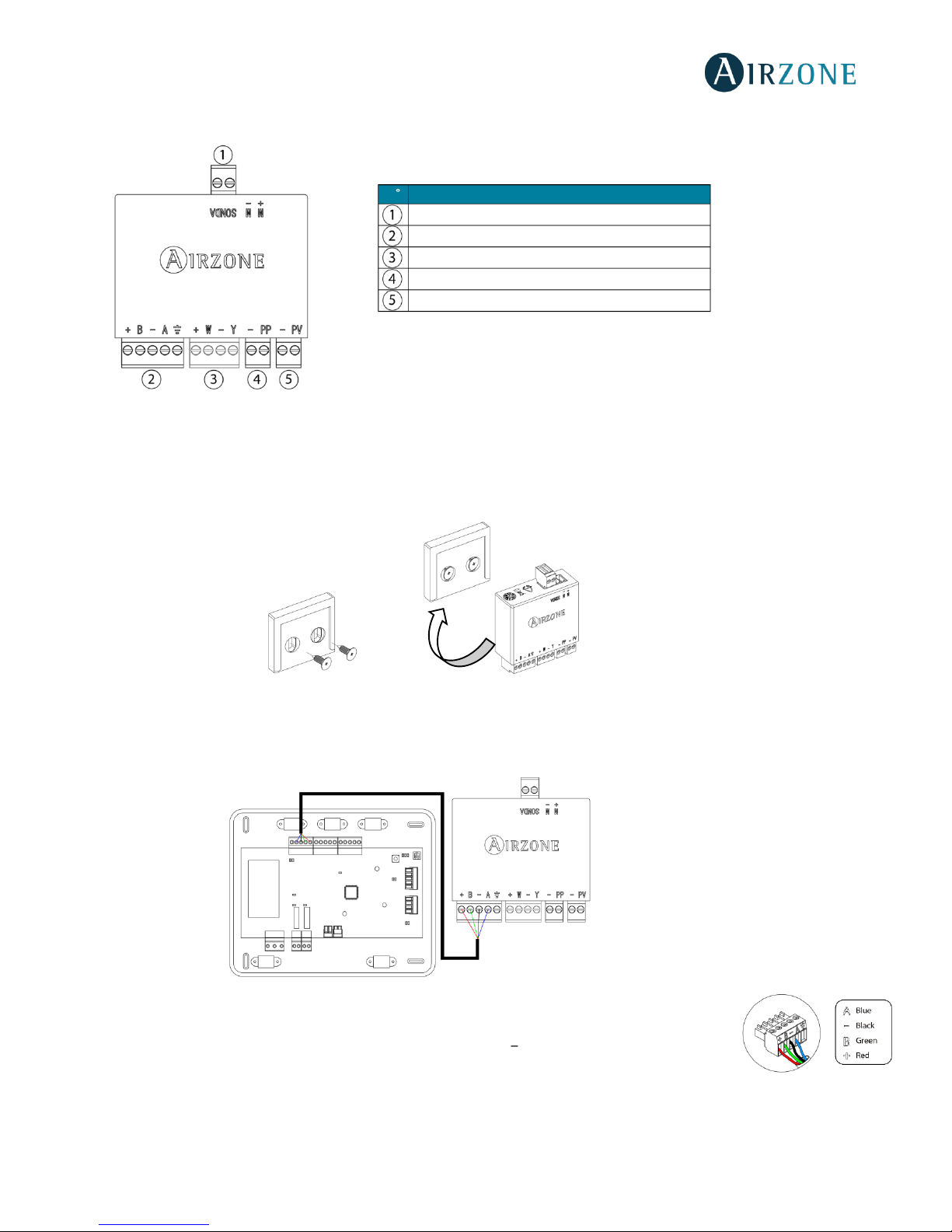
The Intelligent round damper is a device that is connected to the Airzone Connection Bus of the control board (Fig. 11).
It has a 5-pin terminal to connect it to the Airzone Connection Bus of the main board. Use the proper
cable: shielded twisted pair 4 wired: 2x0.22 mm
2 +
2x0.5mm2 (AWG 20 4 wired). Attach the wires with the
terminal screws following the color code (Fig. 12).
It has a 4-pin terminal to connect the thermostat. Use the proper cable: shielded twisted pair 4 wired:
2x0.22 mm
2 +
2x0.5mm2 (AWG 20 4 wired). Attach the wires with the terminal screws following the color
code (Fig. 13).
Remember: The maximum separation between the module and the thermostat is 40 meters.
The zoning module allows you to connect a probe (AZVAF10KPROBE) for remote or distributed temperature reading,
depending on how the module is configured:
• Remote probe: This function allows you to read the room temperature even if you are not where the thermostat is
located. Connect the probe and configure the module as main module (connected thermostat). The state and the setpoint temperature are set via thermostat while the probe reads the room temperature.
• Distributed probe: This function allows you to control a subordinate zone with room temperature reading
independent from the main zone. Connect the probe and configure the module as secondary (disconnected
thermostat). The state and the set-point temperature are set via thermostat while the probe reads the room
temperature.
The module has several inputs to control based on the occupancy or if there are open windows.
N
Meaning
Motorized element connector
Probe connector
Airzone Connection Bus
Thermostat connection
(Only AZVAFDAMPERxxC)
Presence contact
Window contact
Note: Use a shielded twisted pair to connect the window contact.
Fig. 11
Fig. 12
Fig. 13
Page 19
19
• Control by occupancy: When the occupancy sensor connected to the module indicates that the zone is unoccupied,
the system waits for 5 minutes to confirm it is actually empty. After this period of time, the zone is set to Timer Mode
and it turns off after 90 minutes.
• Control by open window: When the open window sensor connected to the module indicates that a window is open
for more than 60 seconds, the control element (actuator/relay) associated with that module closes.
The activation and configuration of these inputs are available in the zone settings menu of the thermostat (See
Advanced
Settings
).
Flow regulation
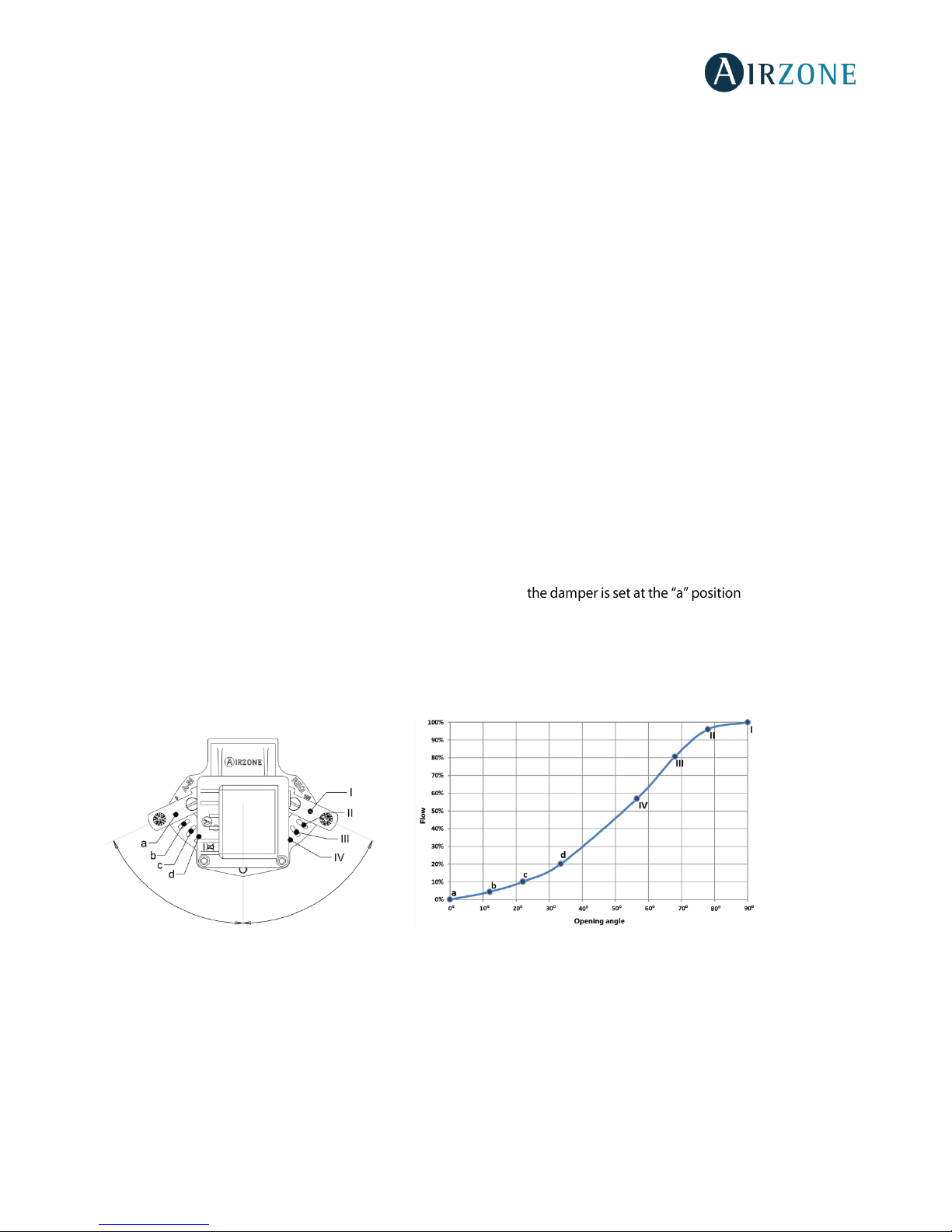
The intelligent motorized dampers include a control system that allows to manually set the maximum and minimum opening
of each damper.
Flow adjustment (REG)
The damper offers a maximum opening adjustment which balances the airflow of each damper based on the real needs of the
installation. By default, the damper is set at the I position. To adjust it, follow the steps:
1. Turn on and generate demand in all zones to open all the dampers.
2. Turn off the zone/damper to be adjusted.
3. Adjust the maximum opening you want with the REG lever (I/II/III/IV).
4. Turn on the zone and check the flow is correct.
Minimum Air Setting (A-M)
The damper enables the adjustment of a minimum opening. By default, . To adjust it, follow
the steps:
1. Turn on and generate demand in all zones to open all the dampers.
2. Adjust the minimum opening you want with the M-A lever (a/b/c/d).
3. Turn on the zone and check the minimum air flow is correct.
A-M
REG
Page 20
20
WIRED/WIRELESS ONLY RADIANT ZONE MODULE (AZVAFZMRAD [C/R])
Assembly
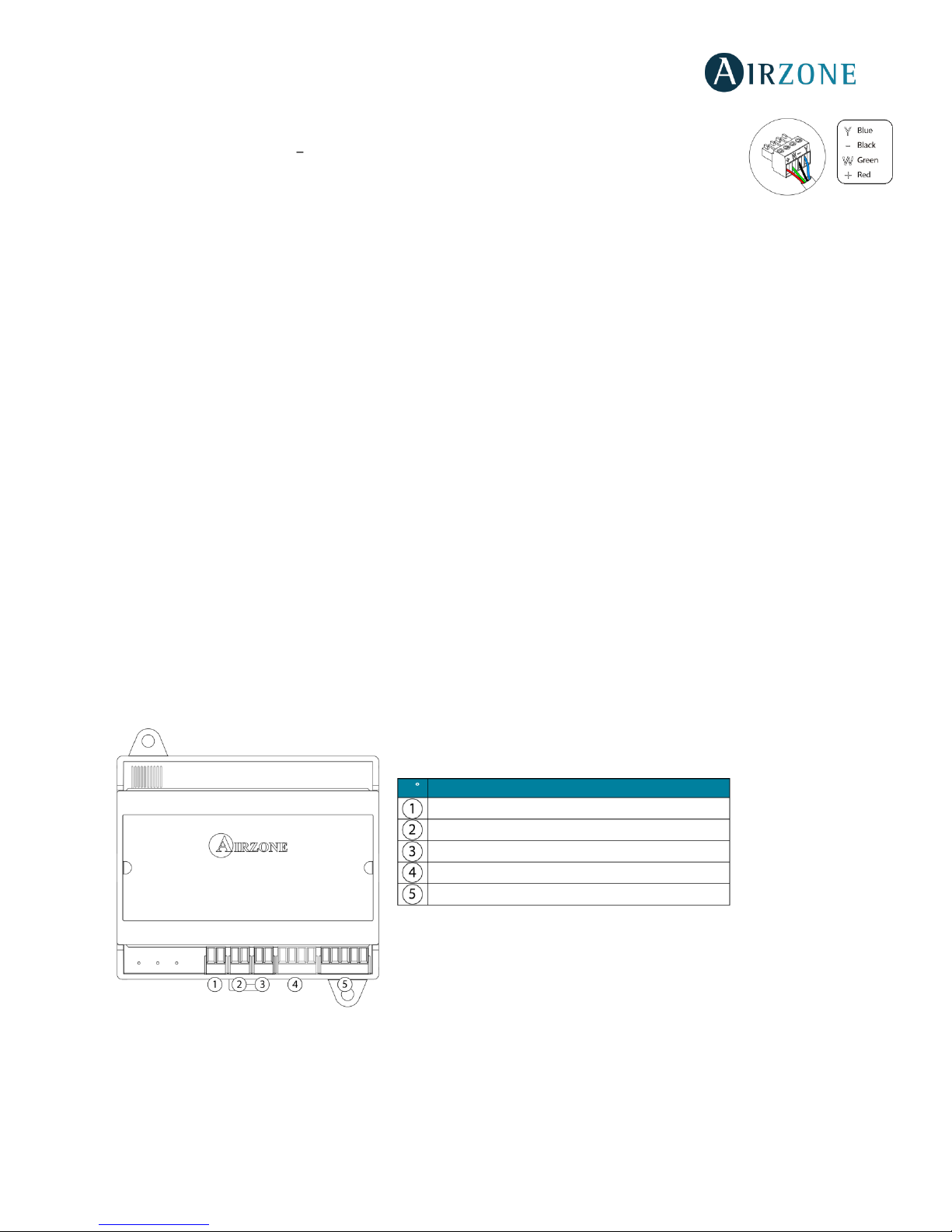
This module is designed to control radiant elements. It is required to have one module per radiant element of the system.
Use the guideway to fix it to the motorized element to be controlled (Fig. 15).
Fig. 15
Connection
The Only Radiant Zone Module is a device that is connected to the Airzone connection bus of the control board (Fig. 16).
It has a 5-pin terminal to connect it to the Airzone Connection Bus of the main board. Use the proper
cable: shielded twisted pair 4 wired: 2x0.22 mm
2 +
2x0.5mm2 (AWG 20 4 wired). Attach the wires with the
terminal screws following the color code (Fig. 17).
Fig. 14
N
Meaning
Probe connector
Airzone connection bus
Thermostat connection
(Only AZVAFZMRADC)
Presence contact
Window contact
Note: Use a shielded twisted pair to connect the window contact.
Fig. 16
Fig. 17
Page 21
21
It has a 4-pin terminal to connect the thermostat. Use the proper cable: shielded twisted pair 4 wired:
2x0.22 mm
2 +
2x0.5mm2 (AWG 20 4 wired). Attach the wires with the terminal screws following the color
code (Fig. 18).
Remember: The maximum separation between the module and the thermostat is 40 meters.
The zoning module allows you to connect a probe (AZVAF10KPROBE) for remote or distributed temperature reading,
depending on how the module is configured:
• Remote probe: This function allows you to read the room temperature even if you are not where the thermostat is
located. Connect the probe and configure the module as main module (connected thermostat). The state and the setpoint temperature are set via thermostat while the probe reads the room temperature.
• Distributed probe: This function allows you to control a subordinate zone with room temperature reading
independent from the main zone. Connect the probe and configure the module as secondary (disconnected
thermostat). The state and the set-point temperature are set via thermostat while the probe reads the room
temperature.
The module has several inputs to control based on the occupancy or if there are open windows.
• Control by occupancy: When the occupancy sensor connected to the module indicates that the zone is unoccupied,
the system waits for 5 minutes to confirm it is actually empty. After this period of time, the zone is set to Timer Mode
and it turns off after 90 minutes.
• Control by open window: When the open window sensor connected to the module indicates that a window is open
for more than 60 seconds, the control element (actuator/relay) associated with that module closes.
The activation and configuration of these inputs are available in the zone settings menu of the thermostat (see Advanced
Configuration).
WIRED/WIRELESS ZONE MODULE WITH XXX COMMUNICATION (AZVAFZM XXX [C/R])
Assembly
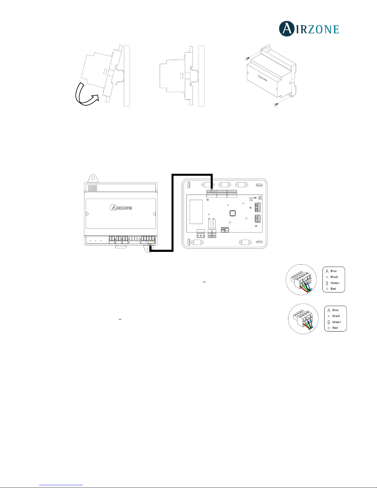
The module is mounted on DIN rail (Fig. 20) or on wall (Fig. 21). It must be placed and mounted in accordance with the current
electrotechnical regulations.
Fig. 19
N
Description
Probe Input
Window contact
Presence contact
Thermostat Connection
(Only AZVAFZMxxxC)
Airzone Connection Bus
Note: Use a shielded twisted pair to connect the window contact.
Fig. 18
Page 22
22
Fig. 20 Fig. 21
Note: To remove the module on DIN rail, pull the tab down to release it.
Connection
The gateway module is a device that is connected to the Airzone connection bus of the control board (Fig. 34).
It has a 5-pin terminal to connect it to the Airzone Connection Bus of the main board. Use the proper
cable: shielded twisted pair 4 wired: 2x0.22 mm
2 +
2x0.5mm2 (AWG 20 4 wired). Attach the wires with
the terminal screws following the color code (Fig. 23).
It has a 4-pin terminal to connect the thermostat. Use the proper cable: shielded twisted pair 4 wired:
2x0.22 mm
2 +
2x0.5mm2 (AWG 20 4 wired). Attach the wires with the terminal screws following the
color code (Fig. 24).
Remember: The maximum separation between the module and the thermostat is 40 meters.
The module allows to connect a probe (AZVAF10KPROBE) for remote or distributed temperature reading, depending on how
the module is configured:
• Remote probe: This function allows you to read the room temperature even if you are not where the thermostat is
located. Connect the probe and configure the module as main module (connected thermostat). The state and the setpoint temperature are set via thermostat while the probe reads the room temperature.
• Distributed probe: This function allows you to control a subordinate zone with room temperature reading
independent from the main zone. Connect the probe and configure the module as secondary (disconnected
thermostat). The state and the set-point temperature are set via thermostat while the probe reads the room
temperature.
The module has several inputs to control based on the occupancy or if there are open windows.
Fig. 22
Fig. 24
Fig. 23
Page 23
23
• Control by occupancy: When the occupancy sensor connected to the module indicates that the zone is unoccupied,
the system waits for 5 minutes to confirm it is empty. After this period of time, the zone is set to Timer Mode and it
turns off after 90 minutes.
• Control by open window: When the open window sensor connected to the module indicates that a window is open
for more than 60 seconds, the control element (actuator/relay) associated with that module closes.
The activation and configuration of these inputs are available in the zone settings menu of the thermostat (see Advanced
settings, Zone settings).
RELAY RADIANT HEAT CONTROL MODULE (AZVAF5OUTPUTS)
Assembly
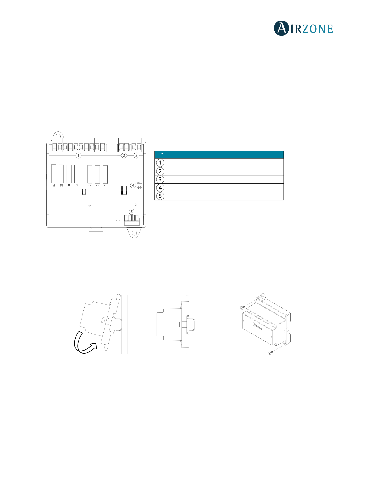
The module is mounted on DIN rail (Fig. 26) or on wall (Fig. 27). It must be placed and mounted in accordance with the current
electrotechnical regulations.
Fig. 26 Fig. 27
Note: To remove the module on DIN rail, pull the tab down to release it.
Fig. 25
N
Description
Zone relay
Pump control relay
Boiler control relay
SW2
Airzone connection bus
Page 24
24
Connection
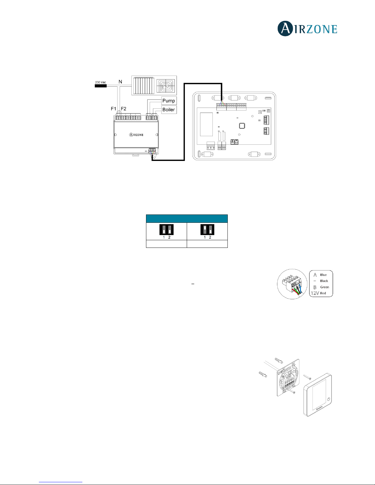
The Relay Radiant Heat Control Module is a device that is connected to the Airzone Connection Bus of the control board
(Fig. 28).
Control relay specs: 24/48 Vac (voltage-free). To control elements of a greater power, it is recommended the use of contactors
in accordance with the power required. Remember to connect the neutral connector directly from the circuit to the element to
be controlled.
The SW2 microswitch configuration (zone ID) is as follows:
Example: The relay to control a radiant element of a module with address 6 is the R1 of the Relay Radiant Heat Control Module
with the address set for the zones 6-10.
It has a 4-pin terminal to connect it to the AC unit bus of the main board. Use the proper cable:
shielded twisted pair 4 wired: 2x0.22 mm
2 +
2x0.5mm2 (AWG 20 4 wired). Attach the wires with
the terminal screws following the color code (Fig. 29).
WIRED THERMOSTATS (AZVAFBLUEFACEC / AZVAFTHINKC / AZVAFLITEC)
Assembly
Airzone thermostats are mounted on the wall through a support. It is recommended not to locate it more than 40 meters away
from the control board. To fix it to the wall, follow these steps (Fig. 30):
• Separate the back part of the thermostat from the wall support and make all the
connections.
• Fix the back part of the thermostat to the wall.
• Place the display on the support once it is fixed.
Fig. 28
SW2
Zones 1 - 5
Zones 6-10
Fig. 30
Fig. 29
Page 25
25
Connection
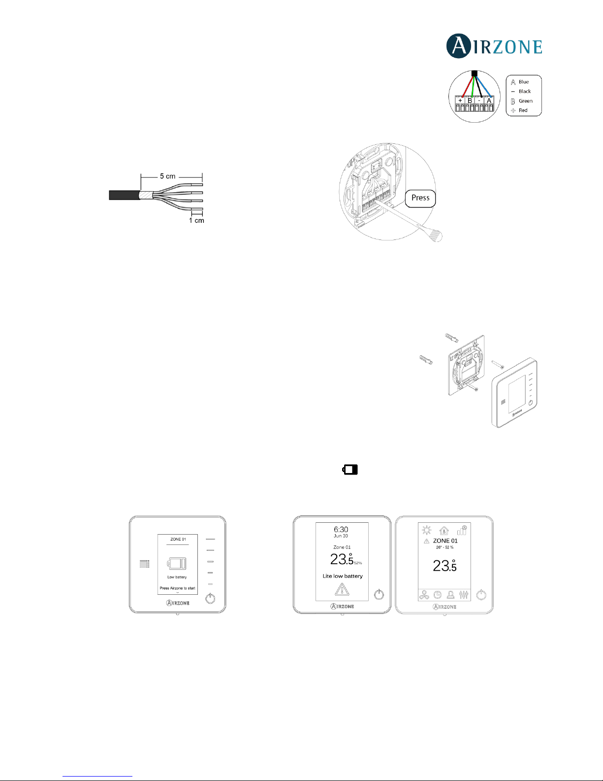
Airzone thermostats are connected to the zone module to be controlled. Attach the wires with the
terminal screws following the color code (Fig. 31).
Important: Use the provided tool to press in the locking tabs (Fig. 32).
WIRELESS THERMOSTATS (AZVAFTHINKR / AZVAFLITER)
Assembly
Wireless thermostats are mounted on the wall through a support. It is recommended not to locate it more than 40 meters away
from the control board.
To fix it to the wall, follow these steps (Fig. 33):
• Separate the back part of the thermostat from the wall support and insert the
CR2450 button battery.
• Fix the back part of the thermostat to the wall.
• Place the display on the support once it is fixed.
Changing batteries
When a Think thermostat is running out of battery, it displays this icon on the screensaver (Fig. 34). In the case of the
wireless Lite thermostats, a warning message will be displayed on the Blueface. In order to know the zone of the Lite
thermostat(s) running out of battery press on the warning icon (Fig. 35).
Fig. 34 Fig. 35
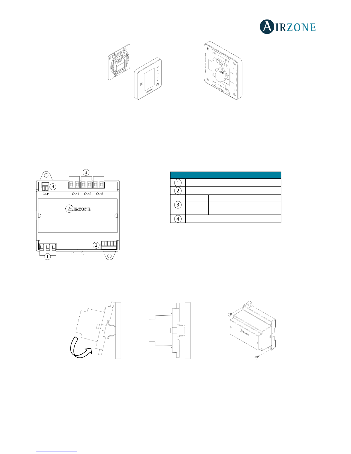
To replace the battery, separate the thermostat from its support and replace the battery (CR2450) (Fig. 36).
Note: For Lite thermostats, the low battery warning will disappear after about 5 minutes from the battery replacement.
Fig. 32
Fig. 31
Fig. 33
Page 26
26
Fig. 36
Important: We recommend using of top-brand batteries. Using low-quality batteries may reduce the duration of use.
Remember to deposit the old battery into an appropriate recycling point.
0-10 V FANCOIL CONTROL GATEWAY (AZVAFGTF10)
Fig. 37
Assembly
The 0-10 V control gateway is mounted on DIN rail (Fig. 38) or on wall (Fig. 39). This module is externally powered at 110/230
Vac. It is should be placed and mounted in accordance with the current electrotechnical regulations.
Fig. 38 Fig. 39
Note: To remove the module on DIN rail, pull the tab down to release it.
Meaning
Power supply
AC unit bus
OUT 1
Cooling air demand
OUT 2
Heating air demand
OUT 3
Fan demand
Fan speed
Page 27
27
Connection
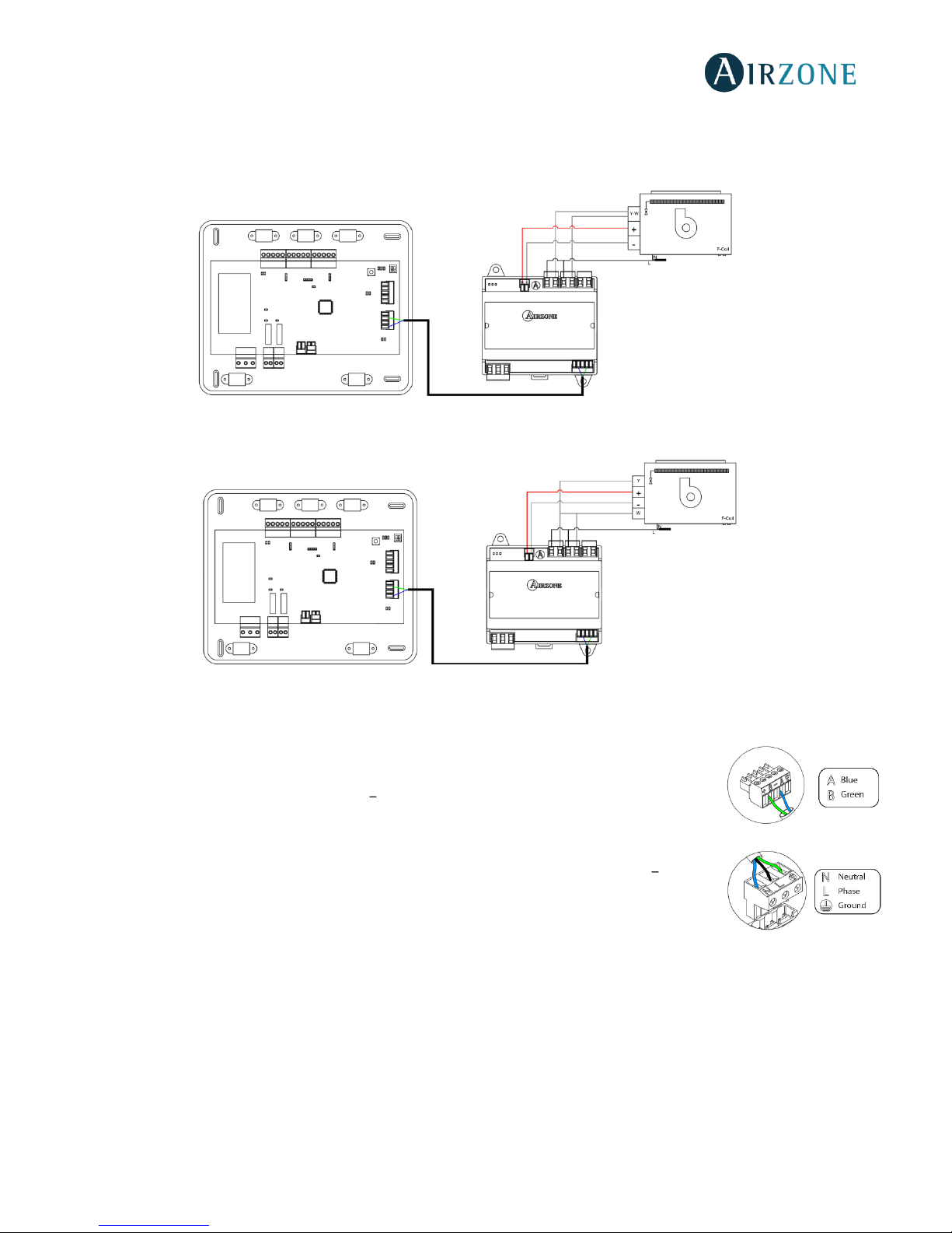
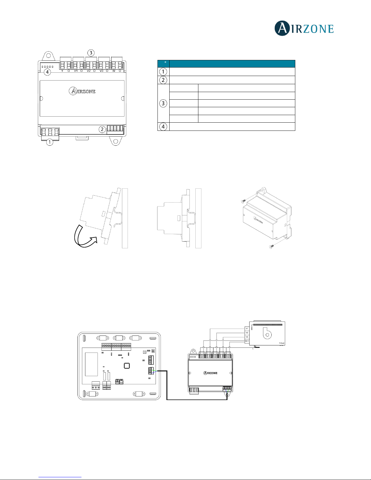
The 0-10 V control gateway is connected to the AC unit bus of the main board (Fig. 40 and 41).
Wiring diagram, 2-pipe installation
Fig.40
Wiring diagram, 4-pipe installation
Fig. 41
Control relay specs: I
max
= 10 A at 110/230 Vac, voltage-free. Note that to control elements with a greater power, it is
recommended to use contactors in accordance with the power required.
It has a 5-pin terminal to connect it to the AC unit bus of the main board. Use the proper cable: shielded
twisted pair 2 wired: 2x0.22 mm2 (AWG 24 2 wired). Attach the wires with the terminal screws
following the color code (Fig. 42).
It is connected to the module through a 3-pin terminal. To do that, use a 3x1.5 mm² (AWG 15 3 wired)
cable. Attach the wires with the terminal screws following the color code (Fig. 43).
Important: According to the current local and national regulations, it is mandatory to add a switch (or
other element to disconnect the system) to the external supply wiring so that a constant separation between poles is
guaranteed. The system will restart automatically if the supply is eventually turned off.
Fig. 43
Fig. 42
Page 28
28
5-RELAY FANCOIL CONTROL GATEWAY (AZVAFGTF5R)
Fig. 44
Assembly
The 5-Relay Fancoil control gateway is mounted on DIN rail (Fig. 45) or on wall (Fig. 46). This module is externally powered at
110/230 Vac. It is should be placed and mounted in accordance with the current electrotechnical regulations.
Fig. 45 Fig. 46
Note: To remove the module on DIN rail, pull the tab down to release it.
Connection
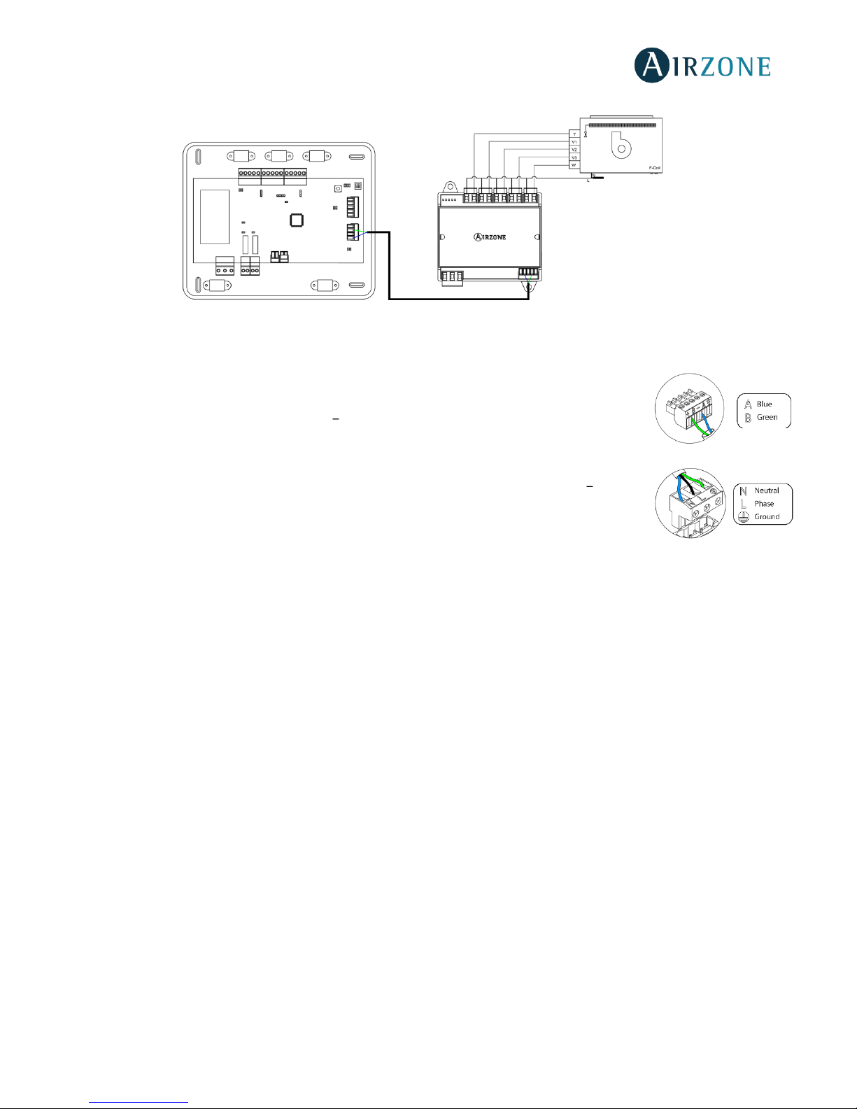
The 5-Relay Fancoil control gateway is connected to the AC unit bus of the main board (Fig. 47 and 48).
Wiring diagram, 2-pipe installation
Fig.47
N
Description
Power supply
AC unit bus
Y-O
Cooling air demand
V1-O
Speed 1
V2-O
Speed 2
V3-O
Speed 3
W-O
Heating air demand
Status LEDs
Page 29
29
Wiring diagram, 4-pipe installation
Fig. 48
Control relay specs: I
max
= 10 A at 110/230 Vac, voltage-free. Note that to control elements with a greater power, it is
recommended to use contactors in accordance with the power required.
It has a 5-pin terminal to connect it to the AC unit bus of the main board. Use the proper cable: shielded
twisted pair 2 wired: 2x0.22 mm2 (AWG 24 2 wired). Attach the wires with the terminal screws
following the color code (Fig. 49).
It is connected to the module through a 3-pin terminal. To do that, use a 3x1.5 mm² (AWG 15 3 wired)
cable. Attach the wires with the terminal screws following the color code (Fig. 50).
Important: According to the current local and national regulations, it is mandatory to add a switch (or
other element to disconnect the system) to the external supply wiring so that a constant separation between poles is
guaranteed. The system will restart automatically if the supply is eventually turned off.
Fig. 50
Fig. 49
Page 30
30
ETHERNET/WIFI CLOUD WEBSERVER (AZVAFWSCLOUD [C/R])
All Airzone systems must be connected to internet to offer technical support.
It is only necessary to connect one Webserver Cloud per installation (control of up to 32 systems).
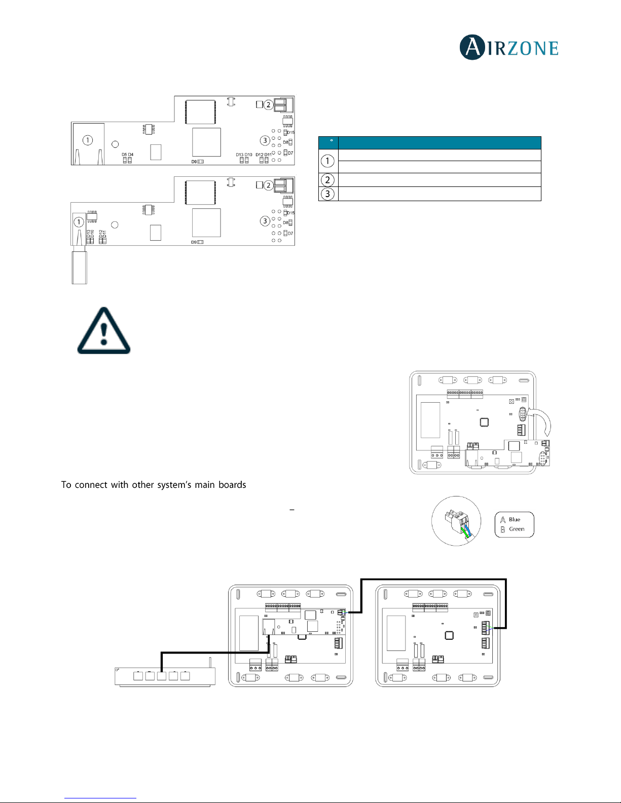
Assembly
The Webserver is integrated into the automation bus of the Control board
(Fig. 52). It has a 5-pin terminal. Disconnect the terminal and fit the connector.
Connection
(Fig. 53), use the 2-pin terminal to
connect the Webserver Cloud to the domotic bus of the main board. Use the proper
cable: shielded twisted pair 2 wired: 2x0.22 mm2 (AWG 24 2 wired). Attach the wires
with the terminal screws following the color code (Fig. 54).
AZVAFWBSCLOUDC
N
Description
Ethernet
WiFi USB connector and antenna
Automation bus output
Automation bus input
Fig. 51
AZVAFWSCLOUDC
AZVAFWSCLOUDR
Fig. 54
Fig. 52
Page 31
31
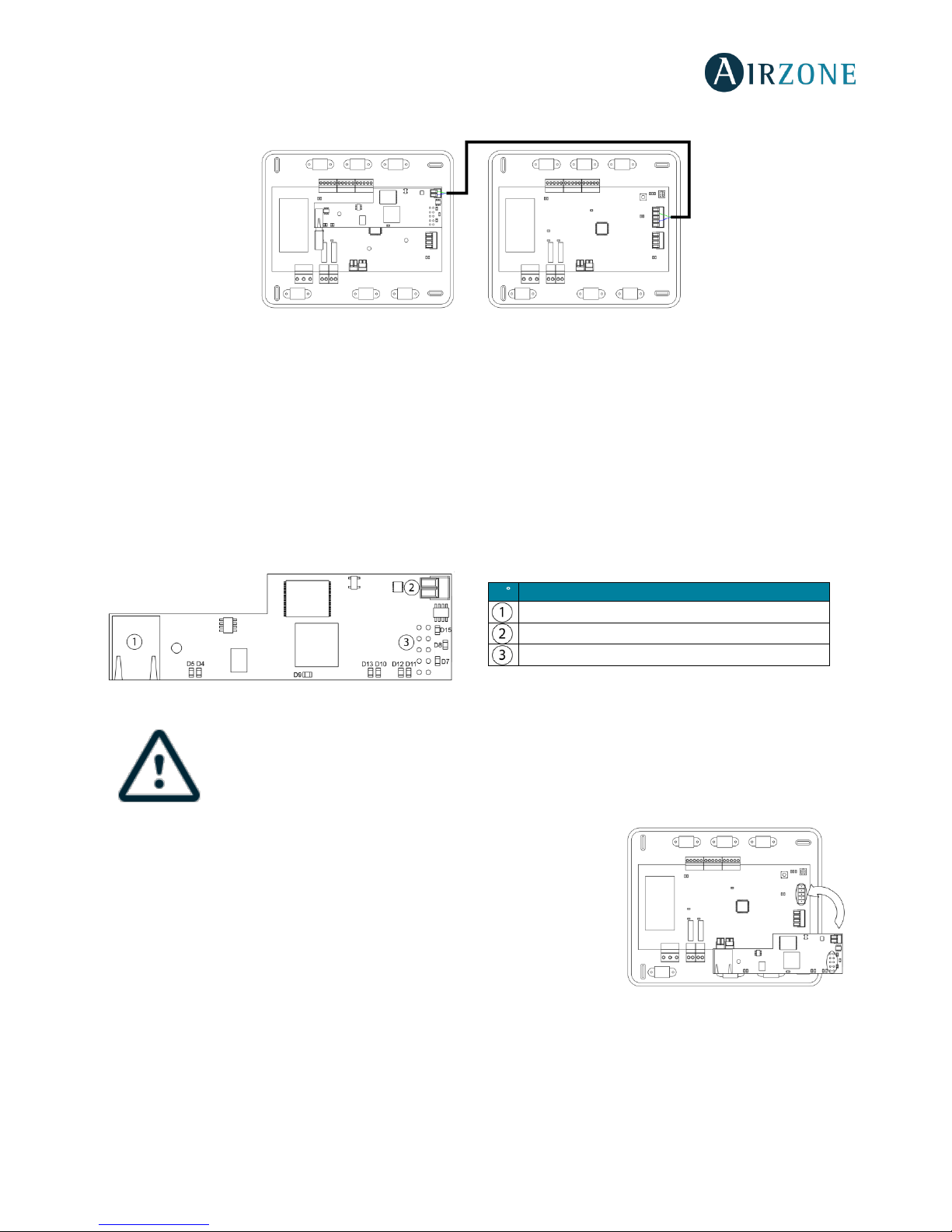
Fig. 53
Note: For a proper operation of this module, all the control boards must be addressed (see section Advanced Settings).
Configuration
To configure it, follow the steps described in the installation manual, available at myzone.airzoneusa.com.
BACNET INTEGRATION GATEWAY (AZVAFBACNETG)
All Airzone systems must be connected to internet to offer technical support.
It is only necessary to connect one BACnet integration gateway per system.
Assembly
The BACnet integration gateway is integrated into the automation bus of the main
board (Fig. 55). It has a 5-pin terminal, disconnect the terminal and insert the
connector.
Configuration
To configure it, follow the steps described in the installation manual, available at
myzone.airzoneusa.com.
AZVAFWSCLOUDR
N
Description
Ethernet
Automation bus output
Automation bus input
Fig. 54
Fig. 55
Page 32
32
ASSEMBLY AND CONNECTION EVALUATION
Check the following aspects:
- The state of the LEDs of the control board and the rest of control elements. Check the self-diagnose section of the data
sheet of the elements.
- All thermostats are powered.
SECONDARY ZONES SETTINGS
IMPORTANT: Can only be configured as secondary zones the zones controlled by a wired zone module.
To set secondary zones, follow these instructions:
- Perform the setup according to the next section.
- Disconnect the thermostat from the secondary module. After a few seconds, this module will be available on the menu
of associated outputs.
- Once all secondary modules are configured, configure all modules or main modules and associate the secondary
modes required.
Note: It is recommended the use of a Blueface thermostat for configuring subordinated zones.
INITIAL SETUP
Once the system has been installed and all the elements are correctly connected, power the system for its setup.
Follow the steps described in the following sections to configure all thermostats.
Important: Before performing the initial set up of the system, configure firstly the subordinated zones, see
Subordinate Zones
Settings
section.
Note: It is recommended to firstly set the thermostats which are going to be configured as main.
BLUEFACE AND THINK THERMOSTATS
Important: Once the setup has been started, it must conclude. You will be able to modify the desired parameters later.
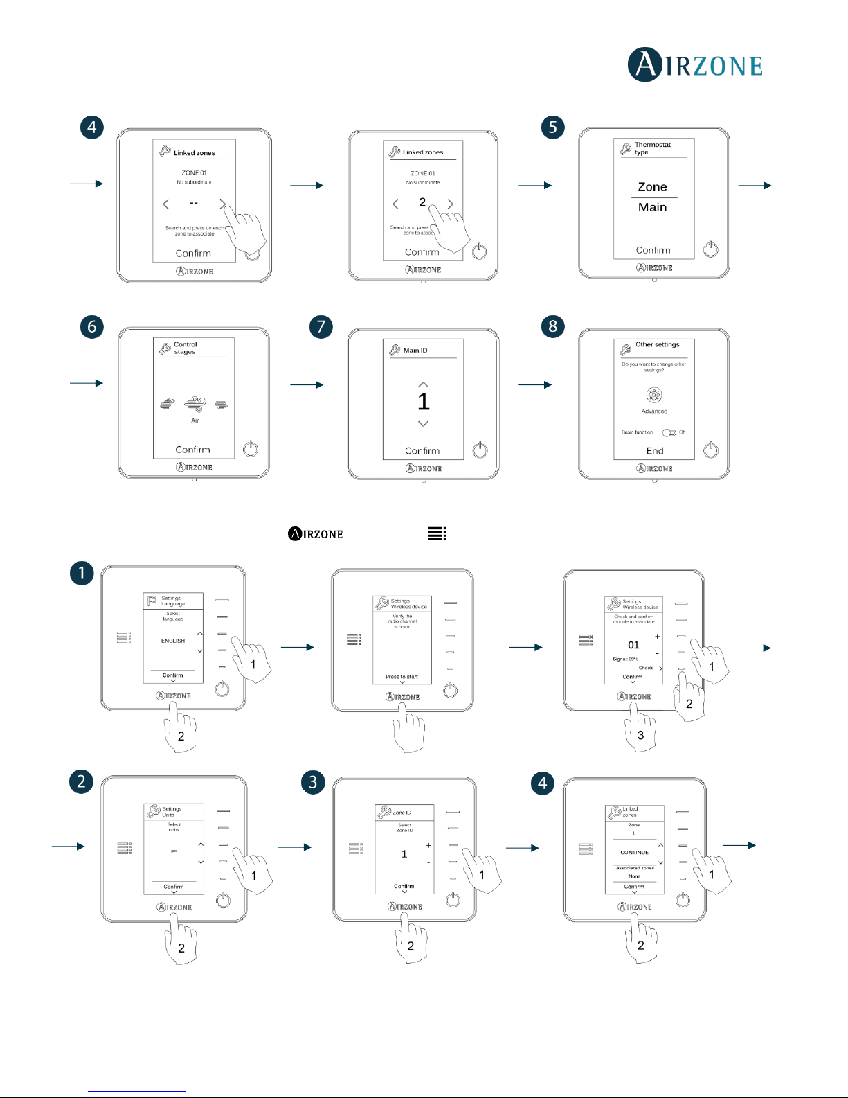
Language
Select your language. These are the available languages: English, French and Spanish.
To associate a wireless Think thermostat, start the radio channel search:
Setting wireless device
- Open the radio channel. To do that, press on SW1. The LED D19 will remain solid red. Once
open, you have 15 minutes to make the association. If that period of time expires, start the
process over again. Remember not to open more than one module at the same time, it may
alter the process. You can also open the channel association radio through the Blueface (see
section
System settings
)
IMPORTANT: Do not to open more than one radio channel at the same time, it may alter the
process.
- Start the radio channel search, to do so, press Airzone to start the search.
- The thermostat will display the different wireless zone modules found, with the signal level of each one of them. Select
the range is
correct (30% minimum) and confirm.
Fig. 56
Page 33
33
IMPORTANT: Before, selecting the zone module which will be associated with the thermostat, check that this module is the
desired one. If this module is not the correct one, use the control bar to select another module and check again.
IMPORTANT: The thermostat will display first the wireless zone modules which are closer to it. Remember to configure this
thermostat near the wireless zone module to associate for greater comfort.
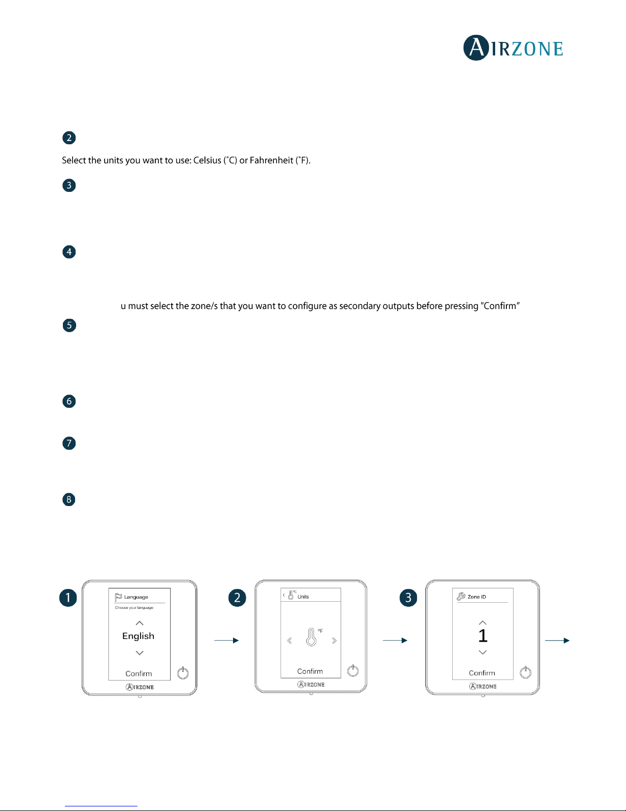
Units
(only if it has not been previously configured by any thermostat)
Zone ID
Select the zone associated to the thermostat. All the zones have a corresponding control output (output for motorized
elements or relay radiant heat control module). For example, the zone 1 will control the control relay output O1 of the relay
radiant heat control module.
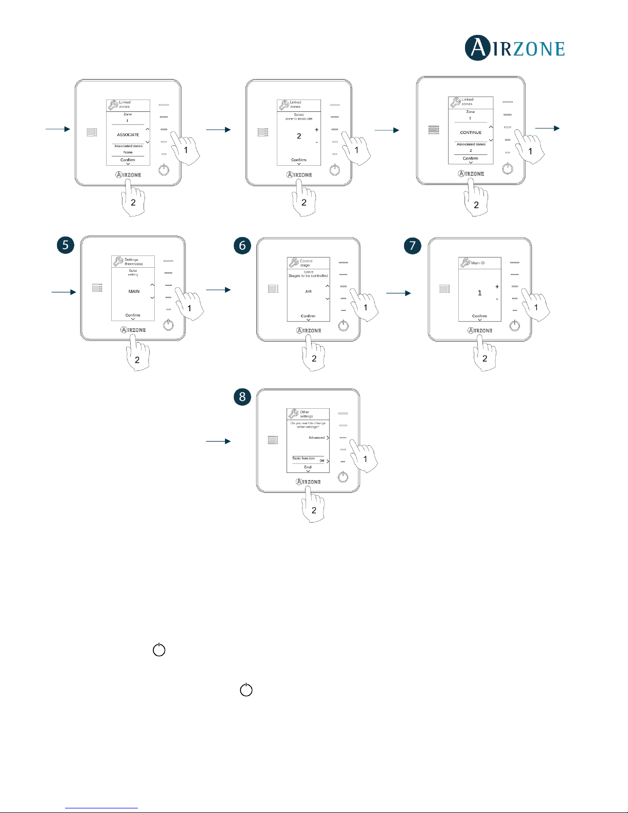
Linked zones
(only if there are previously configured secondary)
If necessary, the system allows you to associate more than one control output to a zone. It is possible to control multiple outputs
from the same thermostat.
Important: Yo .
Thermostat settings
Select the operation of the thermostat:
- Main: Controls all the parameters of the installation.
- Zone: Controls all the parameters of the zone.
Control stages
(only for installations with relay radiant heat control module)
Select stages to be controlled in heating and cooling: Air, Radiant or Air+Radiant.
Main ID
(only if the thermostat has been previously configured as zone)
Select the main thermostat address with which the thermostat is associated. Thus, this main thermostat will impose the
operation mode to the thermostat.
Other settings
Press to conclude the initial setup procedure, or access the advanced settings to change any other settings. Activate the basic
function if required (see
Advanced Settings, Zone settings
).
Blueface
Page 34
34
Think
Important: In Think thermostats, use to confirm and to return to the previous screen or menu.
Page 35
35
LITE THERMOSTATS
To configure a Lite thermostat, follow these steps:
Wired Lite thermostat
- Perform all the appropriate connections.
- Connect the thermostat.
- Press the LED to confirm the association.
- The number of the zone which associates with the thermostat is the lowest free available number.
- If the association is correct, the LED will flash green 5 times.
Wireless Lite thermostat
- Open the wireless association channel of the main board, wait a few seconds so the zone module, which will be
associated to the thermostat, opens its wireless association channel (the wireless opening LED must be solid red).
Page 36
36
- Insert the battery to supply the thermostat.
- Press the LED to begin the wireless search. The LED will blink in green.
IMPORTANT: The thermostat will display first the wireless zone modules which are closer to it. Remember to configure
this thermostat near the wireless zone module to associate for greater comfort.
-
will show the signal level of this module:
o Low signal range level (It is not recommended to perform the association).
o Medium signal range level.
o Good signal range level.
o Excellent signal range level.
- Press the LED to confirm the association, otherwise use to select another module.
- The number of the zone which associates with the thermostat is the lowest free available number.
- If the association is correct, the LED will flash green 5 times. If it flashes red twice, it means the thermostat is out of
range.
REMEMBER: Is required to set the Main ID parameter of the Lite Thermostat for its proper functioning (see section
Advanced
settings Blueface thermostat, Zone settings
).
Configure other functionalities of the LITE thermostat from the advanced configuration menu of a Blueface thermostat (see
section
Advanced settings, Zone settings
) or Webserver Cloud (See Webserver Cloud installation manual).
IMPORTANT: For changing the zone address, access the parameter Zone ID, inside the advanced settings menu from a
Blueface thermostat (see section
Advanced settings, Zone settings
).
Lite thermostat reset
To reset to factory values of any Lite thermostat, turn up the microswitch 8 and place the thermostat on the base again. Press
on , the LED will flash green twice when the reset process is completed.
INITITAL CONFIGURATION EVALUATION
Check the following aspects:
- AC unit-system communication: Choose any mode (except for STOP mode) and switch on the zone to generate
demand. Verify that the selected operation mode in the Main thermostat is shown in the indoor unit thermostat and
the set-point temperature changes.
- Opening-closing of the dampers, ON/OFF of individual AC units and control outputs: Turn on the system and generate
demand in all the zones. Then, switch off and on each zone to verify the element to be controlled operates properly.
- Verify that the static pressure of the duct system complies with the air distribution network conditions where is
).
Important: After the setup or in case of power outage, the system takes a few minutes to measure precisely the temperature
and the relative humidity.
Page 37
37
USER AND ZONE SETTINGS
BLUEFACE THERMOSTAT
User Settings
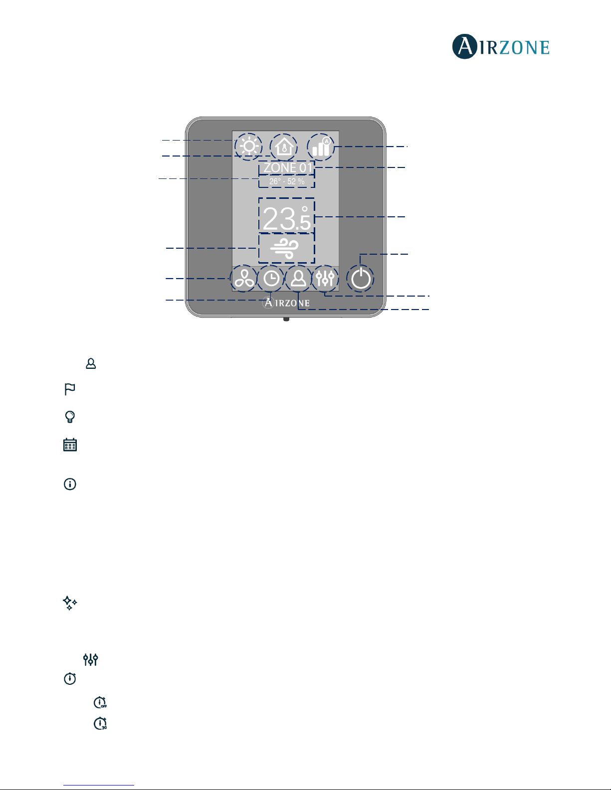
Press to access the menu.
Language. Select the language.
Brightness. Adjust the brightness and enable or disable the screen brightness when the screen saver is active.
Date and time. Press on the clock to set the time and the format type (12 or 24 hours). Press on the calendar to set the
date. Installations with webserver enable automatic time change.
Information. This parameter provides information on:
• Zone: firmware, zone, association, actuator or status of the communications.
• System: firmware, settings and information about the system controllers.
• Devices: It displays the elements connected to the system.
• Webserver (Only for system 1 Main thermostat): firmware, IP address, gateway, MAC and PIN.
• Warnings and errors on system.
Clean screen: Select this option to clean the screen. The touch screen will lock for a few seconds.
Zone Settings
Press to access the menu.
Timer. It is an auto power-off timer of the zone:
Off. Timer is not activated.
30. It activates the timing and switches off the zone after 30 minutes.
Airflow/Fan speed
Current zone/ Zone
navigation menu
Current Set Point
On/Off
Operation mode
Zone demand
Current Room
Temperature/
Relative humidity
User mode
Local ventilation
Time schedule
programming
User settings
Page 38
38
60. It activates the timing and switches off the zone after 60 minutes.
90. It activates the timing and switches off the zone after 90 minutes.
Heating stages *. The available parameters are:
Air: Only uses air stage.
Radiant: Only uses radiant air.
Air+Radiant: The system combines both stages to reach comfort quickly and efficiently.
Note: For security reasons, the zone will turn off after changing any setting.
* Available based on the installation and system setting.
Lite Settings. To save energy, enables to configure the wired Airzone Lite to switch off after a few second.
Note: To access the Lite settings, go to a zone controlled by a Lite thermostat through the zone navigation menu.
THINK THERMOSTAT
Remember: Use to confirm and for going back if browsing submenus.
Setting Parameters
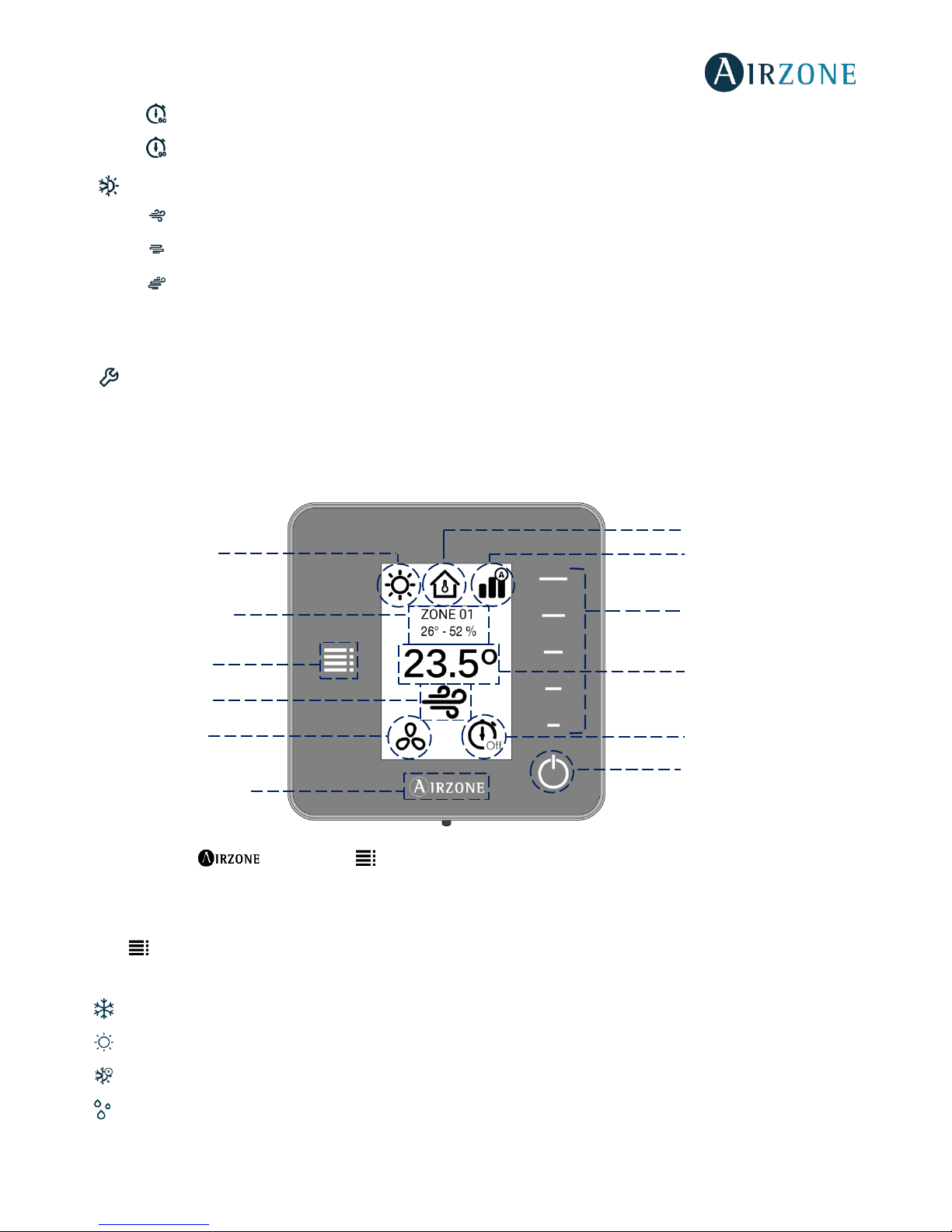
Press to access the menu:
Operation Mode. This parameter is only available when the Think thermostat is configured as main, the available modes are:
Cool. The conditioning unit will start a cooling cycle any time that any zone is in cool demand (T
Set-Point
< T
room
).
Heat. Enables the heating cycle whenever a zone is in heating demand (T
Set-Point
> T
room
).
Auto. The Auto mode allows automatic switching between cool and heat, depending on the global demand.
Dry. In this mode, the air-conditioning unit will start a dehumidification cooling cycle any time that any zone is under
demand (T
Set-Point
< T
room
).
Note: Dry mode decreases humidity in the room by entering the dehumidification cooling cycle.
User Mode
Airflow/Fan speed
Control bar
Current Set Point
Timer
On/Off
Home screen/ Heating
or Cooling Set Point
temperature
Local ventilation
Zone demand
Setting parameters
Zone/ Current Room
Temperature/ Relative
humidity
Operation Mode
Page 39
39
Emergency Heat. This mode activates the Auxiliary Heat to provide heated air in case of a mechanical failure in the system.
Note: This mode is only visible when the installation includes an auxiliary heating device.
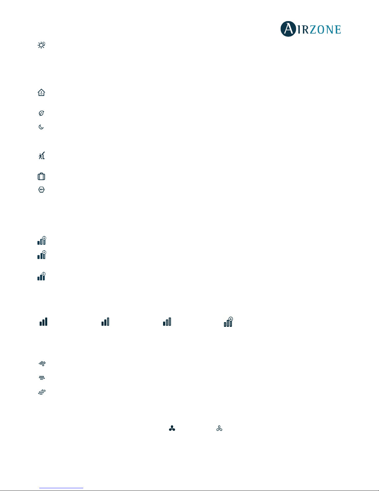
User Mode. This parameter is only available when the Think thermostat is configured as main, the available modes are:
Comfort. Default and standard user mode. The desired set point temperature can be selected using the predefined
temperature ranges.
Eco. The range of available set point temperatures change for more efficient operation.
Night time. The system automatically changes the set point temperature 0.5º C/1º F every 30 minutes in up to 4 increments
of 2º C/4º F in 2 hours. When cooling, the system increases the set point temperature; when heating, the system decreases
the set point temperature.
Unoccupied. To be used when there is no presence detected for short periods of time. A more efficient set point
temperature will be set. If the thermostat is activated, the zone will start running in comfort mode.
Vacation. This mode feature saves energy while the user is away for extended periods of time.
Stop. The air-conditioning system will remain switched off regardless of the demand status of any zone, all the motorized
dampers will remain opened.
Airflow control. This parameter is only available when the Think thermostat is configured as main of a zoned system, selects
the control algorithm that best fits the installation. The available options are:
Silence. The fan speed is lower than in standard mode to reduce the noise.
Standard. Set by default. The system automatically regulates the fan speed based on the number of zones calling for
cooling or heating.
Power. The fan speed is higher than in standard mode to increase the flow.
Fan Speed. This parameter is only available on Fancoil installations, it is used to set the airflow control of the AC unit fan. The
airflow control is set in automatic mode by default, imposing the flow depending on the number of zones in demand.
High speed Medium speed Low speed Low speed
Heating stages. This option is only available if the zone is configured as air+radiant configuration and enables to choose the
stage of the zone. The available parameters are:
Air. Only uses air stage.
Radiant. Only uses radiant air.
Air+radiant. The system combines both stages to reach comfort quickly and efficiently.
Note: For security reasons, the zone will turn off after changing any setting.
Local Ventilation. This option enables the activation or deactivation of the ventilation in the selected zone when the
system is not actively cooling or heating any of the zones.
Page 40

40
Timer. It is an auto power-off timer of the zone.
Off. Timer is not activated.
30. It activates the timing and switches off the zone after 30 minutes.
60. It activates the timing and switches off the zone after 60 minutes.
90. It activates the timing and switches off the zone after 90 minutes.
Information. This parameter provides information about:
• Zone: firmware, zone, association, actuator or communication status.
• System: firmware, settings and information about the system controllers.
• Devices: displays the elements connected to the system.
• Webserver (Only for system 1 Main thermostat): firmware, IP address, gateway, MAC and PIN.
Main zone. This parameter is only available when the Main thermostat of the group is lost. Enables to access and to modify the
operation mode of the group.
Page 41
41
ADVANCED SETTINGS
ADVANCED SETTINGS BLUEFACE THERMOSTAT
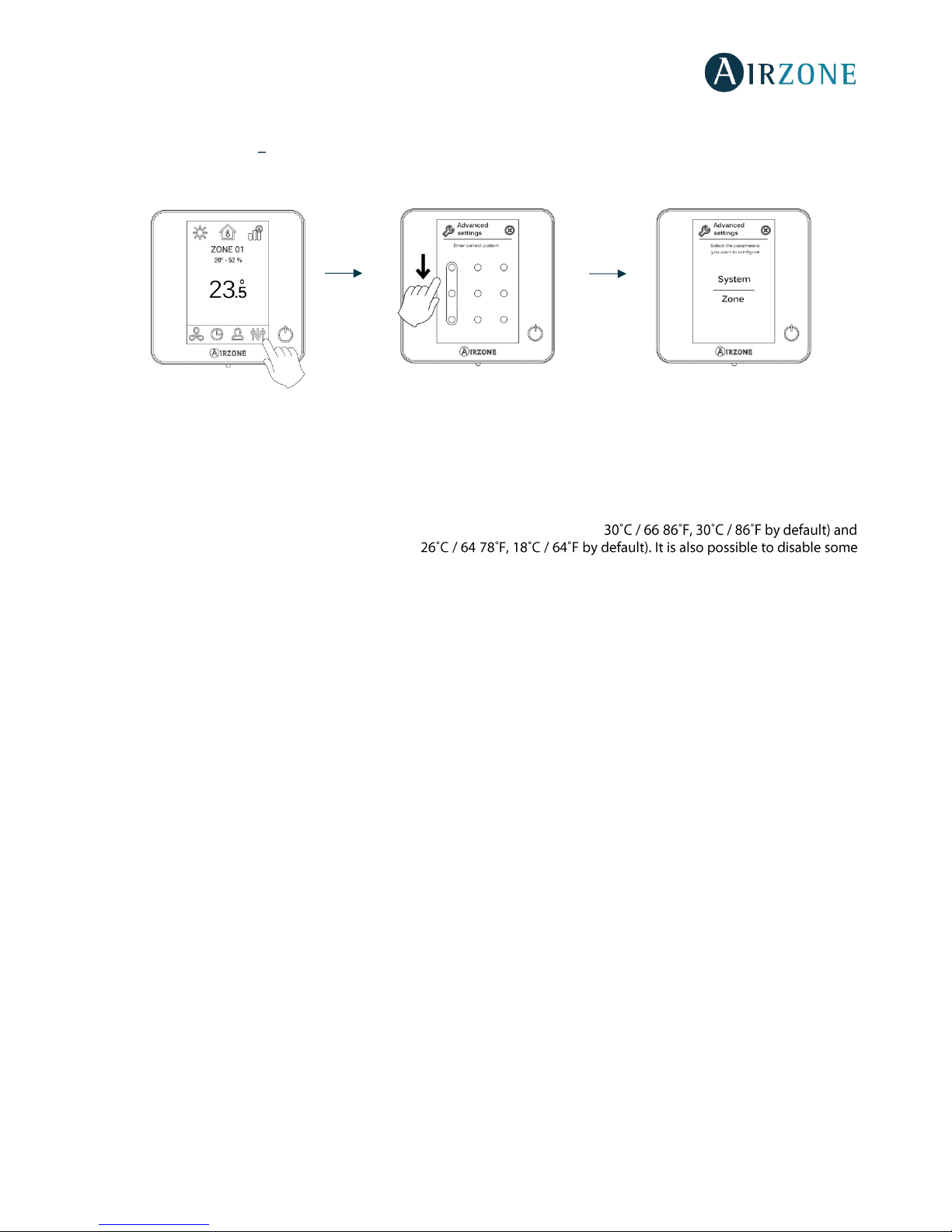
To access the advanced configuration menu, follow the next steps:
From this menu you can control both the zone parameters and the system parameters.
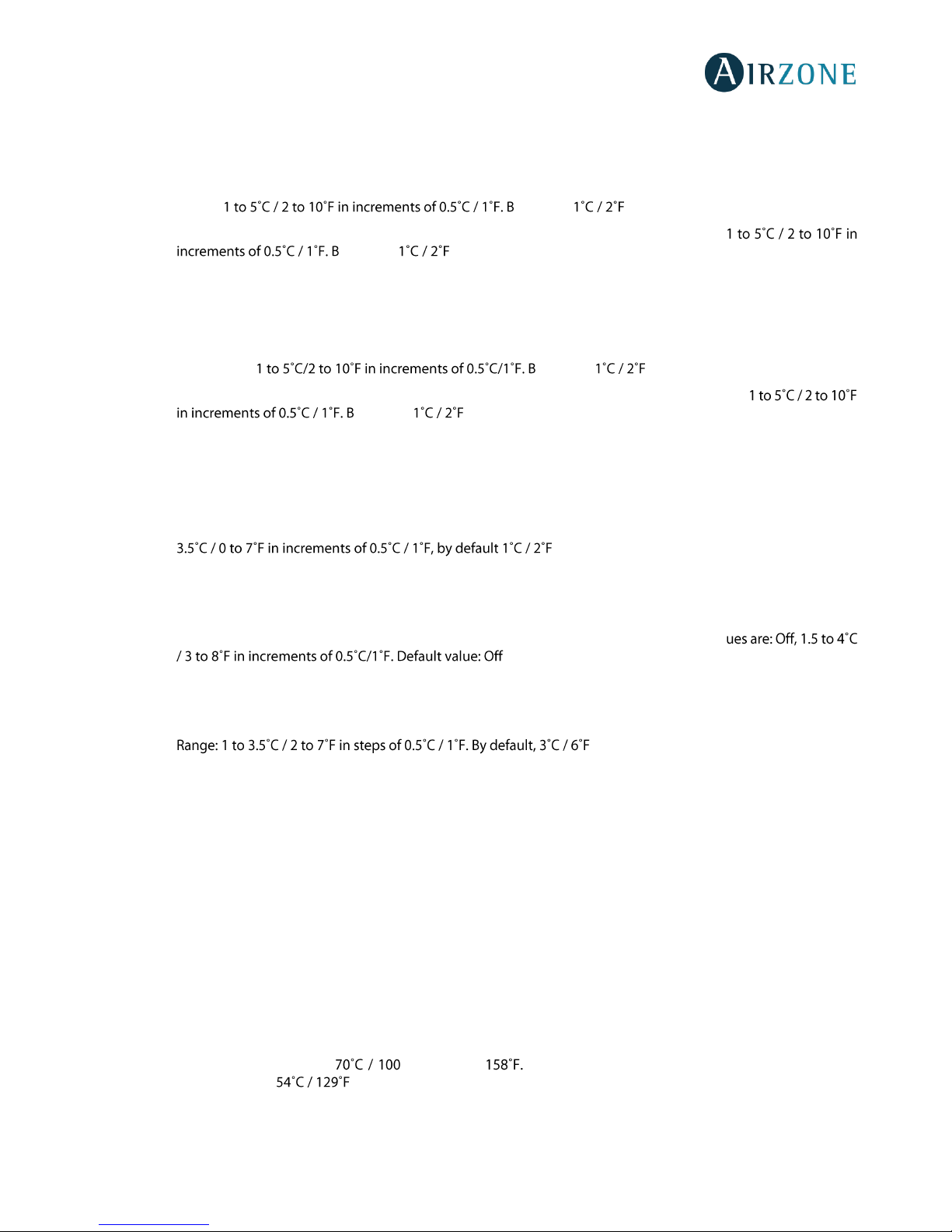
System settings
• System ID. Defines the number of the system within your installation.
• Temperature range. Selects the highest temperature in heating mode (19- -
the lowest temperature in cooling mode (18- of the modes.
• Global Ventilation. This menu allows you to activate/deactivate the fan mode in all zones when the system is not
actively heating or cooling any zones. By default, the global ventilation is deactivated. When activated, the following
settings are used to configure Global Ventilation:
o Every (min). Configure the length of the interval (in minutes) between periods of ventilation. Configurable
from 5 to 40 minutes, in 5 minutes increments (by default, 15 minutes).
o Run For (min). Configure the time duration that ventilation is activated (in minutes). Configurable from 5 to
20 minutes, in 5 minutes increments (by default, 10 minutes).
Note: when global ventilation is activated, a warning message will appear on the screensaver.
• Anti-freezing. This feature prevents the room temperature from lowering below 12˚C / 53˚F, although your zone is off.
It is deactivated by default.
• Type of opening
(only available in installations with intelligent damper)
. Use this parameter to configure the type of
opening of the damper output: All/Nothing or Modulating (by default).
*Note: If you change this parameter, all the dampers of the installation will be affected.
• Minimum air
(only available in installations with intelligent damper and with the parameter Type of opening
configured as modulating).
Enables/disables the entry of a minimum airflow in zones where the set point temperature
has been reached. When the zone is off, the damper shuts completely.
*Note: If you change this parameter, all the dampers of the installation will be affected.
• Auxiliary Heat. This menu is used to enable/disable the auxiliary heat. By default, the auxiliary heat is disabled. When
auxiliary heat is enabled, the following parameters are used to configure the operation of the auxiliary heat:
Configuration Menu
o Available Stages. Defines how many stages of auxiliary heat a system has.
o First Supply Heat. If the setting for Auxiliary heat is 1 or 2, then the first system to supply heat must be defined
as either: Heat Pump or Aux. Heat.
o Fan Configuration. Select between Electric (Fan on) or Furnace (Fan off) option. If you select Electric option,
define:
Press and hold
Page 42
42
▪ Fan Delay (s). Defines the delay time (in seconds) to turn off the fan when there is no demand from
the Auxiliary Heater. Possible values are 0, 45, 60 and 120 seconds.
First Stage Menu
- First Stage Differential. Temperature that the system has to surpass to activate the first stage of auxiliary heat.
Values: y default, .
- First Stage Hysteresis. Defines the hysteresis for the operation of the first stage. Values:
y default, .
- Min. Time Exhausted. Minimum time that the Heat Pump must be active before the first stage of auxiliary heat
can be activated. Possible values are 0, 45, 60 and 120 minutes. By default, 45 minutes.
Second Stage Menu
- Second Stage differential. Temperature that the system has to surpass to activate the second stage of auxiliary
heat. Values: y default, .
- Second Stage Hysteresis. Defines the hysteresis for the operation of the second stage. Values:
y default, .
- Min. Time Exhausted. Minimum time that the first stage must be active before the second stage of auxiliary heat
can be activated. Possible values are 0, 45, 60 and 120 minutes. By default, 45 minutes.
• Autochange. This option allows the user to configure the three values that define the auto-changeover operation that
sets the mode of the indoor unit.
- Setpoint Differential. Defines the minimum differential between heating and cooling set points. Values: 0 to
.
- Mode Switching Protection (min). Defines the minimum run time before allowing a mode change. Possible
values are 15, 30, 60 and 90 minutes. By default, 30 minutes.
- Heat OVR Temp. If a zone has a higher heating demand than this temperature, the system reverts heating
operation even if the cooling global demand exceeds the global heat demand. Possible val
.
• Away mode settings. This option configures the following parameters of the unoccupied user mode and the vacation
user mode:
- Hysteresis. If the set point temperature is surpassed by the differential defined, the zone will cease demand.
.
- Override Time. Sets time that the zone will resume the selected away mode when the user touches the
thermostat screen during an away period. Values: 10 to 120 minutes in steps of 10 minutes. By default, 60 minutes.
• Heating stage. This option configures the following parameters of the Air+Radiant control stage (see parameter
Control stages
for more information):
- Temperature gap. Defines the temperature gap after which the second stage must be activated.
- First stage. Defines the first stage to operate: Air or Radiant.
• BACnet. This parameter displays the Device ID, the uplink port, the IP address, the subnet mask and the Gateway IP
and allows you to modify them. Press on the value you want to change, modify it and then press to confirm. The values
by default are:
- Device ID: 1000
- Port: 47808
- IP Address: DHCP
• Supply temperature
(only available in installations with Airzone VAF 10 KOhm NTC thermistor).
This option allows
the system demand to be ignored if the supply temperature exceeds a certain limit. The selectable heating cut out
temperatures are 38-46-54-62- -114-129-143- By default, the system will stop heating if the supply
temperature reaches .
Note: The system will not generate heat until past 4 minutes (minimum) from the shut of demand.
• Room temperature. This option allows the room temperature and relative humidity to be shown/hidden. By default,
the room temperature is shown.
Page 43
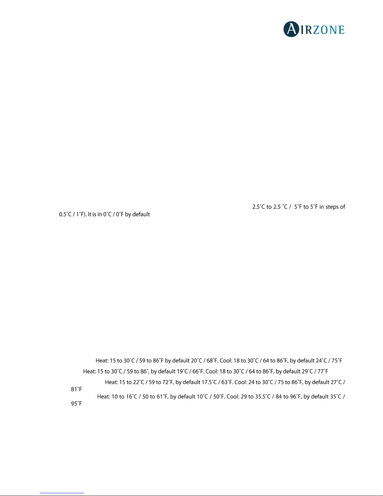
43
• Radio channel. It activates/deactivates the radio channel of the system.
• Reset system
(only available for main thermostat)
. Resets the system and returns to factory settings. To reconfigure
the thermostats, please check
Initial setup
. Wait 60 seconds until the system restarts before connecting again.
Zone settings
• Zone ID
(only available from remote zones, in zones controlled by Lite thermostats)
. Shows and allows to modify the
zone number assigned among the availables.
Important: It is necessary to set the Main ID parameter of the thermostat for its proper functioning.
• Linked zones. It displays and allows you to select the control outputs associated with the thermostat.
• Thermostat settings. Use this parameter to define the thermostat as Main or Zone.
• Main ID
(only available if the thermostat is configured as zone).
Sets the main zone, which imposes its mode to this
zone (only set-point temperature and fan speed features will be configurable.
• Use mode. The thermostats can be set in Basic or Advanced mode. They are set in Advanced mode by default. These
are the parameters you can control in basic mode: On/off, set-point temperature, airflow/fan speed and operation
mode. If you need to reset the thermostat to Advanced mode, access the advanced configuration menu and then
activate the advanced use mode.
• Offset. Correction factor for the room temperature of the zones (range: from - -
.
• Control stages. This parameter is used to select cooling/heating stages in the zone. These are the features to be
configured:
- Air: It activates the heating air in the zone.
- Radiant: It activates radiant heating.
- Air+Radiant: It activates both air and radiant heating in the zone and also allows the user to select the desired
heating stage: Air, Radiant or Air+Radiant.
- Off: It deactivates the cooling/heating stage in the zone.
• Occupancy contact. It determines the state of the module of a zone based on the occupancy. It only has effect on the
zone module if it is associated to a thermostat (it does not operate in secondary zone modules). When this contact is
on, if the zone is empty for over 5 minutes, the Timer 90 feature is activated (displaying an Occupancy notification on
the thermostat). It is off by default. In order to activate this feature, configure it as Normally open or Normally closed.
• Window contact. This option allows the control the state of a zone module based on the opening of the window. It
only has effect on the control element of the zone module. When this contact is on, if it detects any open window, it
turns off the zone after 60 seconds (displaying an Open window notification on the thermostat). It is off by default. In
order to activate this feature, configure it as Normally open or Normally closed.
• User mode setpoint. This option is used to configure the set point temperature of each user mode for each zone:
- Comfort. .
- Eco. .
- Unoccupied.
.
- Vacation.
.
• Weight. This option is used to set the weight of each zone for purposes of determining system operation. The weight
of the zone will be used for calculating the mode (auto-change over) or for calculating heat demands when using
auxiliary heat. It is an indicator of the size / importance of the zone. Possible values range from 0-100. By default, the
weighting is set to Auto and each zone's weight is automatically generated based on the number of zones. For
example, if there are four zones, each zone's weight is automatically set to 25. If this option is disabled, the weight of
the zone can be set manually.
• Reset thermostat
(not available in remote zones)
. Allows you to reset the thermostat and returning it to the default
values.
Page 44
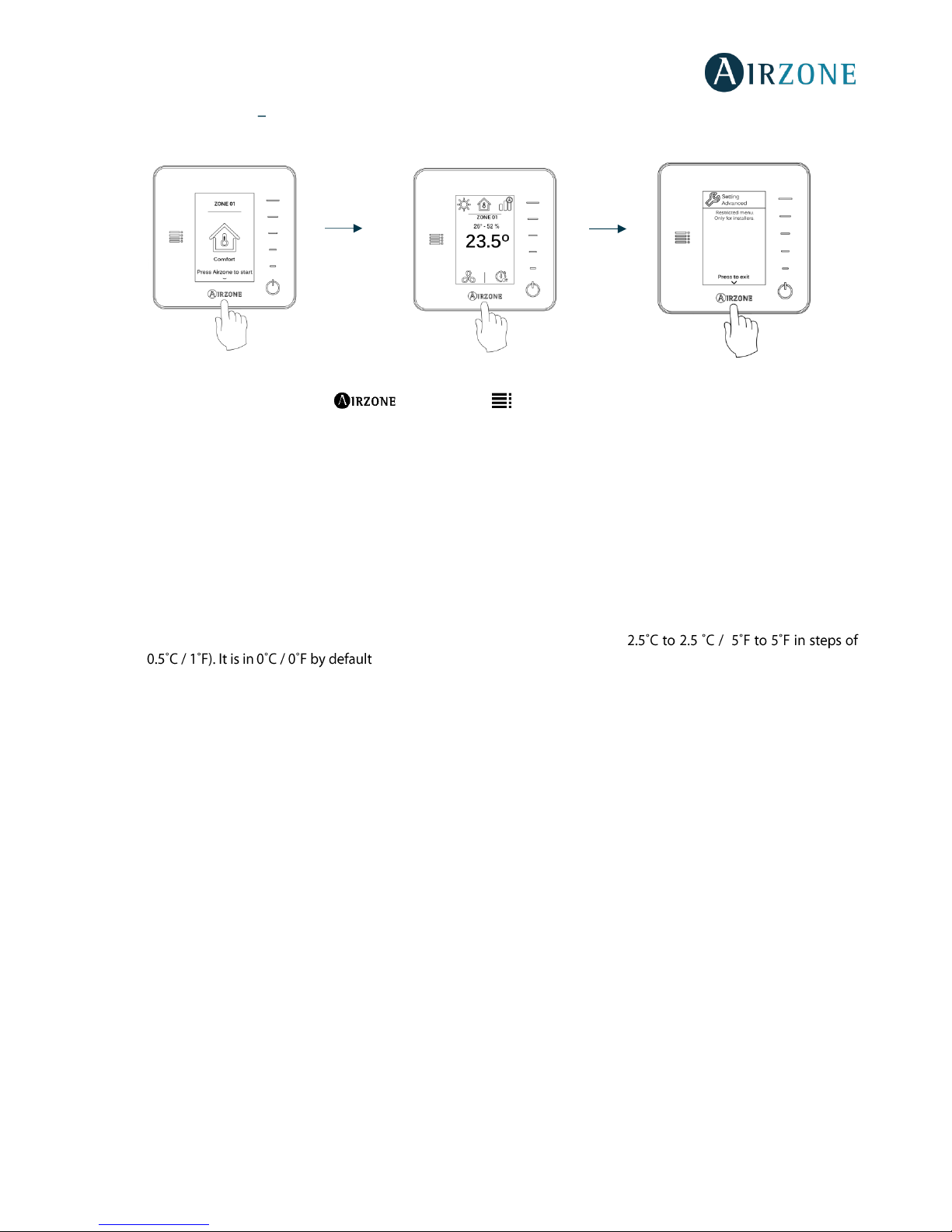
44
ADVANCED SETTINGS THINK THERMOSTAT
To access the advanced configuration menu, follow the next steps:
Important: In Think thermostats, press to confirm and to return to the previous menu/screen.
• Linked zones. It displays and allows you to select the control outputs associated with the thermostat.
• Thermostat settings. Use this parameter to define the thermostat as Main or Zone.
• Main ID
(only available if the thermostat is configured as zone).
Sets the main zone, which imposes its mode to this
zone (only set-point temperature and fan speed features will be configurable).
• Use mode. The thermostats can be set in Basic or Advanced mode. They are set in Advanced mode by default. These
are the parameters you can control in basic mode: On/off, set-point temperature, airflow/fan speed and operation
mode.
If you need to reset the thermostat to Advanced mode, access the advanced configuration menu and then activate
the advanced use mode.
• Offset. Correction factor for the room temperature of the zones (range: from - -
.
• Control stages. This parameter is used to select cooling/heating stages in the zone. These are the features to be
configured:
- Air: It activates the heating air in the zone.
- Radiant: It activates radiant heating.
- Air+Radiant: It activates both air and radiant heating in the zone and also allows the user to select the desired
heating stage: Air, Radiant or Air+Radiant.
- Off: It deactivates the cooling/heating stage in the zone.
• Occupancy contact. It determines the state of the module of a zone based on the occupancy. It only has effect on the
zone module if it is associated to a thermostat (it does not operate in secondary zone modules). When this contact is
on, if the zone is empty for over 5 minutes, the Timer 90 feature is activated (displaying an Occupancy notification on
the thermostat). It is off by default. In order to activate this feature, configure it as Normally open or Normally closed.
• Window contact. This option allows the control the state of a zone module based on the opening of the window. It
only has effect on the control element of the zone module. When this contact is on, if it detects any open window, it
turns off the zone after 60 seconds (displaying an Open window notification on the thermostat). It is off by default. In
order to activate this feature, configure it as Normally open or Normally closed.
• Weight. This option is used to set the weight of each zone for purposes of determining system operation. The weight
of the zone will be used for calculating the mode (auto-change over) or for calculating heat demands when using
auxiliary heat. It is an indicator of the size / importance of the zone. Possible values range from 0-100. By default, the
weighting is set to Auto and each zone's weight is automatically generated based on the number of zones. For
example, if there are four zones, each zone's weight is automatically set to 25. If this option is disabled, the weight of
the zone can be set manually.
• Reset thermostat. Allows you to reset the thermostat and returning it to the default values.
Press once
Press and hold
Press and hold
Page 45
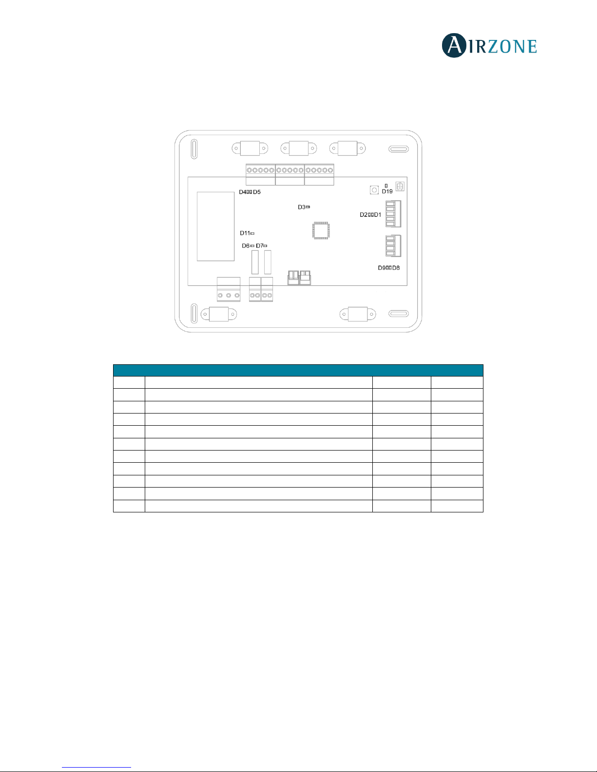
45
SELF-DIAGNOSE
CONTROL BOARD (AZVAFRXXXX)
Airzone control boards have integrated LEDs that detect unusual operations.
Fig. 57
Meaning
D1
Data reception from automation bus
Blinking
Green
D2
Data transmission from automation bus
Blinking
Red
D3
Control board activity
Blinking
Green
D4
Data transmission from Airzone Connection Bus
Blinking
Red
D5
Data reception from Airzone Connection Bus
Blinking
Green
D6
1st Stage Auxiliary heat activated
Switches
Green
D7
2nd Stage Auxiliary heat activated
Switches
Green
D8
Data transmission from AC unit bus
Blinking
Red
D9
Data reception from AC unit bus
Blinking
Green
D11
Control board power supply
Steady
Red
D19
Association channel: active
On
Red
Page 46
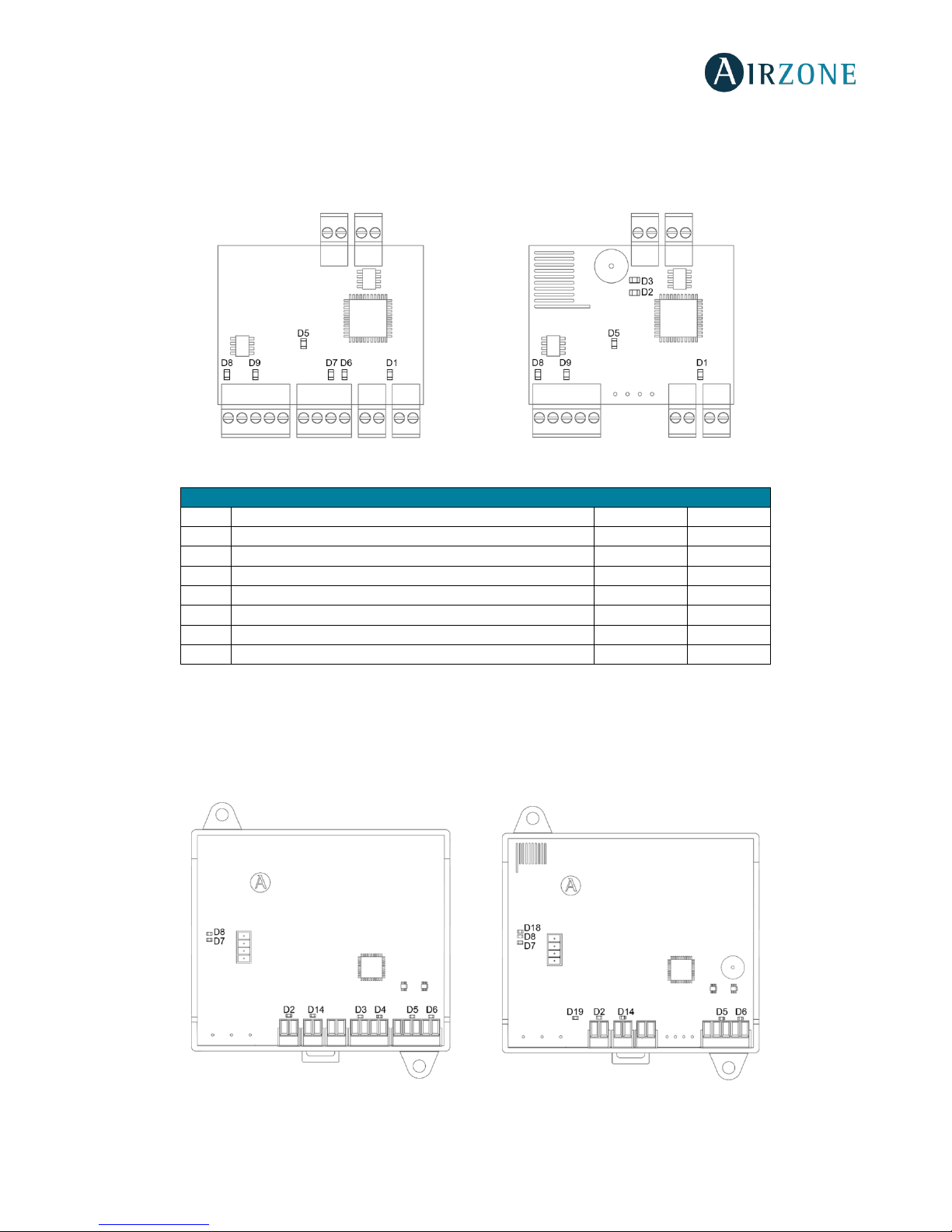
46
WIRED/WIRELESS INTELLIGENT ROUND DAMPER AND WIRED/WIRELESS ONLY RADIANT ZONE MODULE
(AZVAFDAMPERXXX [C/R] AND AZVAFZMRAD [C/R])
The intelligent round damper module and only radiant zone module have integrated LEDs that detect unusual operations.
Fig. 58
WIRED/WIRELESS ZONE MODULE WITH XXX COMMUNICATION (AZVAFZM XXX [C/R])
The zone modules have integrated LEDs that detect unusual operations.
Fig. 59
AZVAFDAMPERxxxC and AZVAFZMRADC AZVAFDAMPERxxxR and AZVAFZMRADR
Meaning
D1
Module operating
Blinking
Green
D2
Wireless data packets reception
Switches
Green
D3
Association channel: active
Steady
Red
D5
Power supply
Steady
Red
D6
Data reception from thermostat
Blinking
Green
D7
Data transmission from thermostat
Blinking
Red
D8
Data reception from Airzone connection bus
Blinking
Green
D9
Data transmission from Airzone connection bus
Blinking
Red
AZVAFZMxxxC AZVAFZMxxxR
Page 47
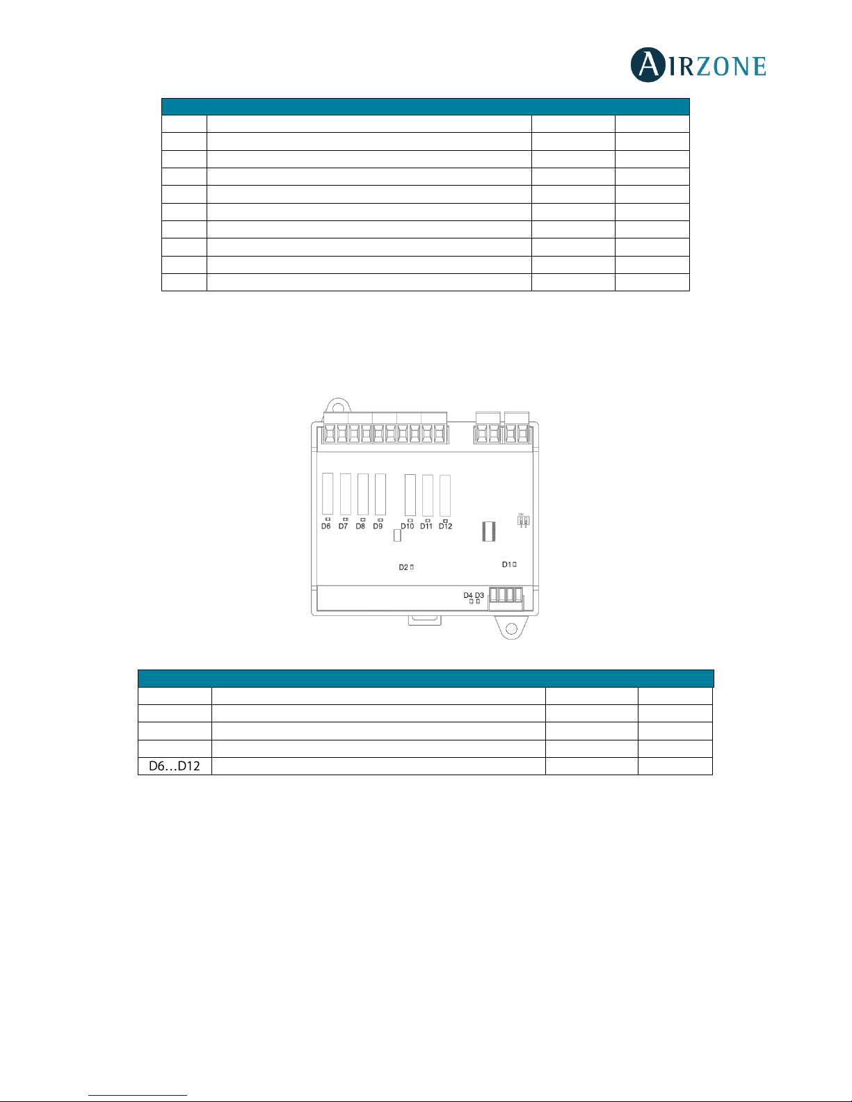
47
RELAY RADIANT HEAT CONTROL MODULE (AZVAF5OUTPUTS)
The relay radiant heat control modules have integrated LEDs that detect unusual operations.
Fig. 60
Meaning
D2
Power supply
Steady
Red
D3
Data transmission from thermostat
Blinking
Red
D4
Data reception from thermostat
Blinking
Green
D5
Data transmission from Airzone connection bus
Blinking
Red
D6
Data reception from Airzone connection bus
Blinking
Green
D7
Data transmission from gateway
Blinking
Red
D8
Data reception from gateway
Blinking
Green
D14
Module operating
Blinking
Green
D18
Wireless data packets reception
Switches
Green
D19
Association channel active
Steady
Red
Meaning
D1
Power supply
Steady
Red
D2
Module operating
Blinking
Green
D3
Data reception from Airzone connection bus
Blinking
Green
D4
Data transmission from Airzone connection bus
Blinking
Red
Leds of relay state
Blinking
Green
Page 48
48
BLUEFACE AND THINK THERMOSTATS (AZVAFBLUEFACEC / AZVAFTHINK [C/R])
Blueface and Think Thermostat Warnings
Thermostat displays all the system warnings on the screensaver. If there is any error, it will be displayed on the screensaver, on
the main screen and on tio , inside the User settings menu.
• Anti-freezing
(only Blueface)
. It will be only displayed when it is activated (See
Advanced Configuration Blueface
thermostat, system parameters
).
• Unoccupied Override. A zone has been activated while the user mode is set on Unoccupied. The system will start
using the Comfort Mode during the selected override time. When the override time has expired, the system returns to
its previous status.
• Vacation Override. A zone has been activated while the user mode is set on Vacation. The system will start using the
Comfort Mode during the selected override time. When the override time has expired, the system returns to its
previous status.
• Window. It indicates the air conditioning of the zone has been deactivated due to open window. Only available if the
window contact of the system is activated.
• Global ventilation
(only Blueface)
. The global ventilation is activated.
• Occupancy. It indicates no occupancy has been detected in the zone for the last 5 minutes. Therefore, the Timer
function is activated (the zone will switch off after 90 minutes). Only available for systems with occupancy.
• Low Battery Lite
(only Blueface)
. Low battery warning. Informs about the involved zone when the icon is pressed.
Note: For Lite thermostats, the low battery warning will disappear after about 5 minutes from the battery replacement.
• Battery
(only Think wireless).
Low battery warning.
Blueface and Think Thermostats errors
If any type of anomaly is detected, the word "Error" is displayed on the screensaver of these devices. You may find the following
errors:
Error 1: Communication error between wired thermostat and zone module
(AZVAFDAMPERxxC / AZVAFZMRADC / AZVAFZMxxxC)
This incident blocks the control of the zone. To solve this incident check:
1. Connection: Check the polarity of the connectors of the module and the thermostat.
2. Wiring: Check that the voltage between the poles (A /-) and (B/-) is about 0.65 Vdc.
3. Wiring: Verify that the module connection bus-thermostat is not next to low-voltage wiring.
4. Module: Check the correct operation of the module, for this connect another thermostat and verify that the error
disappears.
5. Restart the zone and re-associate it with the system:
- Blueface thermostats: Press on Reset to restart the device. If the error persists, press and hold on and reset the
thermostat. Configure the system.
- Think thermostats: To do this, press and hold on and restart the start-up configuration process.
6. Restart system: If the system is restarted, this error may be displayed in the thermostats at the beginning of the process.
This message should disappear after around 30 seconds.
Page 49
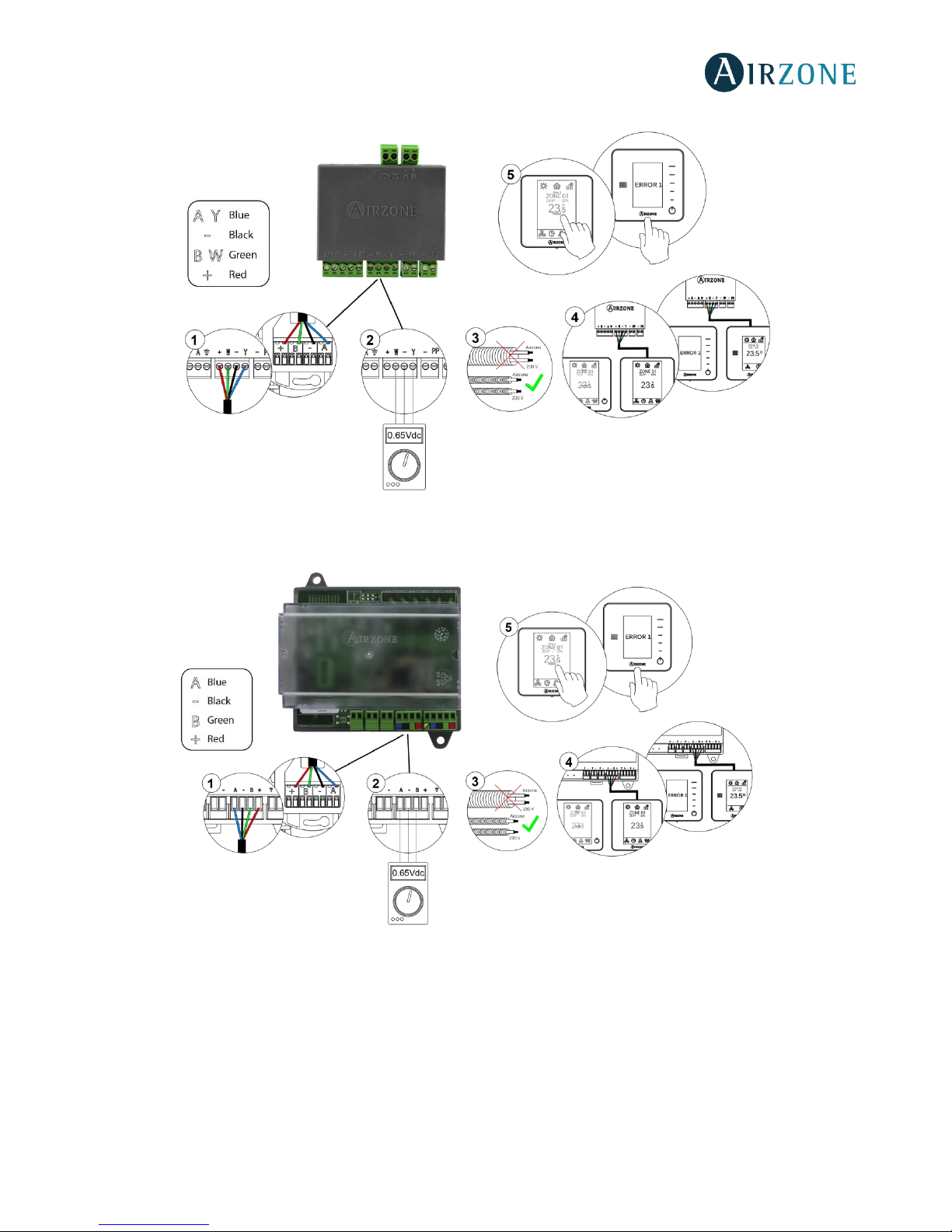
49
AZVAFDAMPERxxC / AZVAFZMRADC
Fig. 61
AZVAFZMxxxC
Fig. 62
Error 1: Communication error between wireless thermostat and zone module
(AZVAFDAMPERxxR / AZVAFZMRADR / AZVAFZMxxxR)
This incident blocks the control of the zone. To solve this incident check:
1. Thermostat status: Check the signal range of the thermostat with the module through the Information parameter (see
section
Advanced settings, system settings
) or approach the thermostat to the module if the thermostat recovers the
communication, it is necessary to relocate it as it was out of range.
2. Module status: Correctly powered.
Page 50
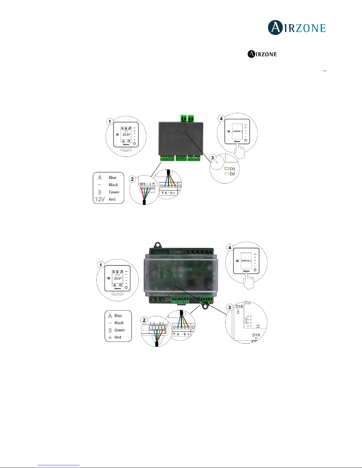
50
3. Module status: Proper operation of the LED of wireless communication.
4. Restart the zone and re-associate it with the system. To do this, press and hold on and restart the start-
up configuration process. Note that, if you need to associate wireless devices, the wireless association module must
be previously open (from SW1 button or from any thermostat, pressing
Wireless module
inside
Advanced Settings
Think thermostats) .
5. Restart system: If the system is restarted, this error may be displayed in the thermostats at the beginning of the process.
This message should disappear after around 30 seconds.
AZVAFDAMPERxxR / AZVAFZMRADR
Fig. 63
AZVAFZMxxxR
Fig. 64
Error 2: Communication error between control board and zone module
(AZVAFDAMPERxx [C/R] / AZVAFZMRAD [C/R] / AZVAFZMxxx [C/R])
This incident blocks the control of the zone. Check this error is not common to all thermostats. If so, verify the proper operation
of the main board. To solve this incident check:
1. Control board status: Correctly powered.
2. Control board status: Airzone Connection Bus LEDs are operating properly.
3. Connection: Verify the polarity of the control board and thermostat connectors.
Page 51
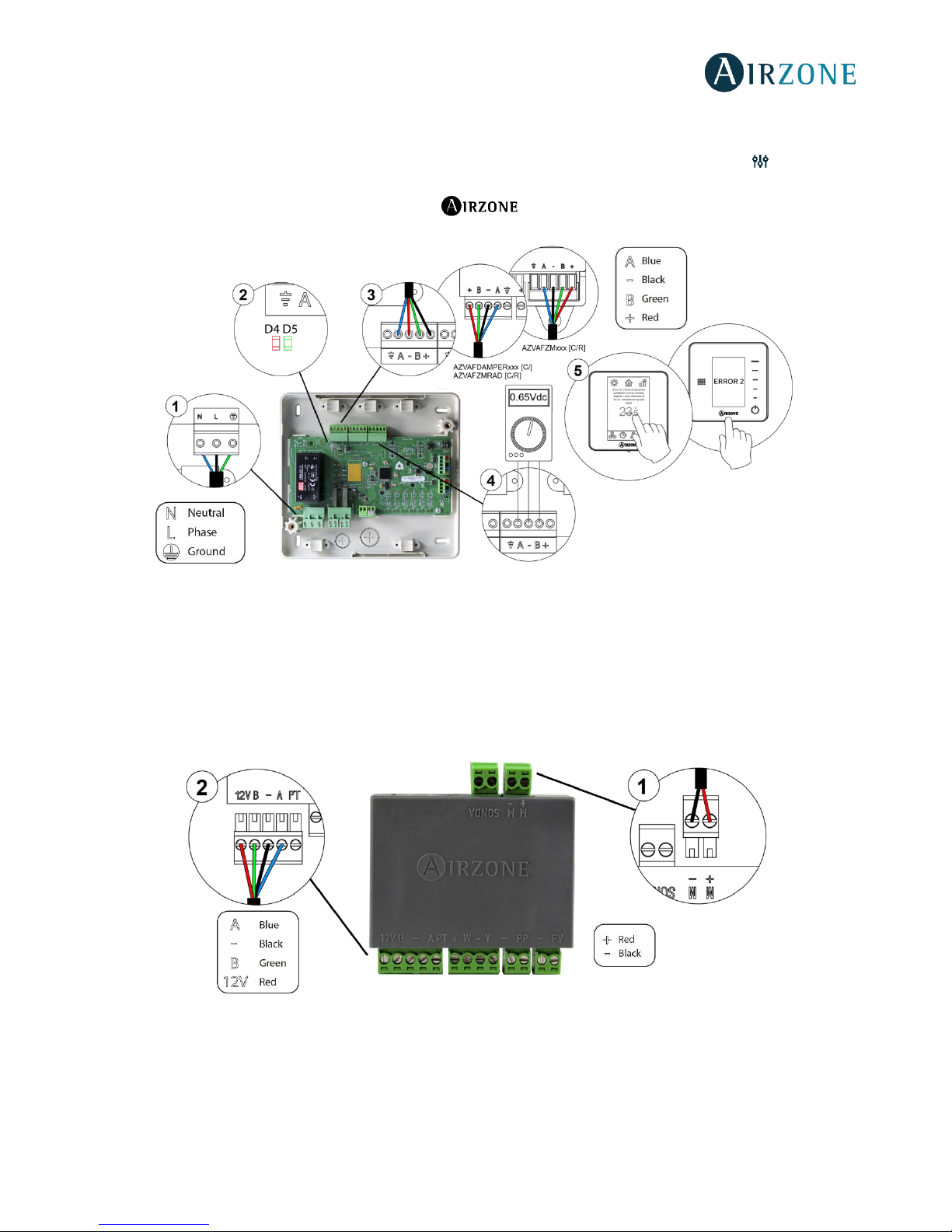
51
4. Wiring: Check that the voltage between the poles (A /-) and (B/-) is about 0.65 Vdc.
5. Restart the zone and re-associate it with the system:
- Blueface thermostats: Press on Reset to restart the device. If the error persists, press and hold on and reset the
thermostat. Configure the system.
- Think thermostats: To do this, press and hold on and restart the start-up configuration process.
Fig. 65
Error 3: Motorized element not connected to the actuator output
The system does not detect any motorized element connected to the motor output. Check the state of the connection
terminal of the actuator output of the zone module:
1. Status of the connection terminal in the actuator output of the zone module.
2. Disconnect and connect the terminal of the Airzone connection bus.
Fig. 66
Error 4: Motorized element blocked
The system detects that the motorized element has an abnormality and blocks the opening-closing movement. Disconnect
and connect the Airzone connection bus terminal and check if the error disappears, otherwise, proceed to the replacement of
the device or sent it for repair.
Page 52
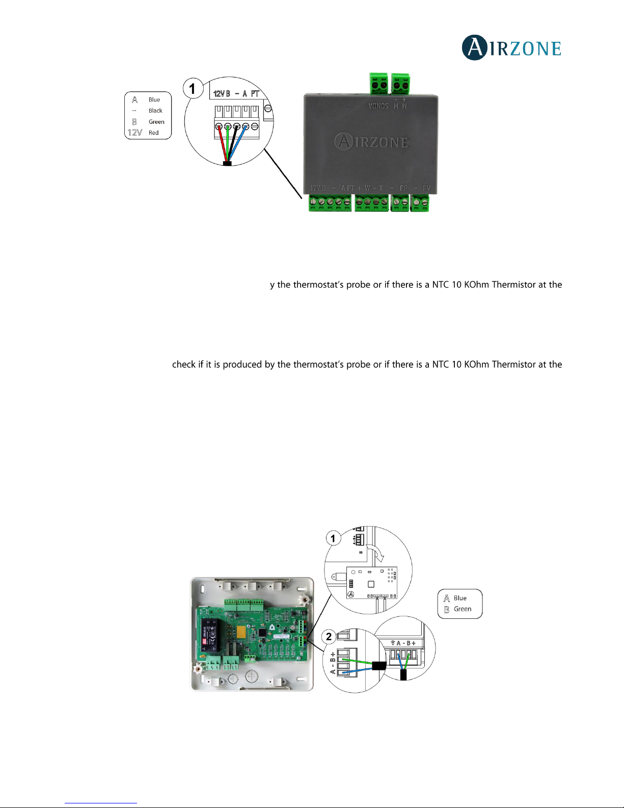
52
Fig. 67
Error 5: Temperature probe - Open circuit
The zone ceases to measure the room temperature; therefore, the zone cannot generate demand. Proceed to replace it of the
device or sent it for repair (check if it is produced b
probe output of the zone module).
Error 6: Temperature probe - Short circuit
The zone ceases to measure the room temperature; therefore, the zone cannot generate demand. Proceed to replace it of the
device or sent it for repair (
probe output of the zone module).
Error 9: Gateway-System communication error
The system loses communication with the AC unit. The system will open all the zones and deactivate the control from the
thermostats, only allowing the operation of the unit from the thermostat of its manufacturer. To solve this incident check:
1. Verify the gateway is properly connected to the AC unit port of the control board.
2. In DIN-rail gateways, check the polarity of the connectors of the gateway and the AC unit port of the main board.
3. Check the status of the LEDs of the gateway. To do this check the self-diagnose section or the technical sheet of the
gateway.
Fig. 68
Page 53
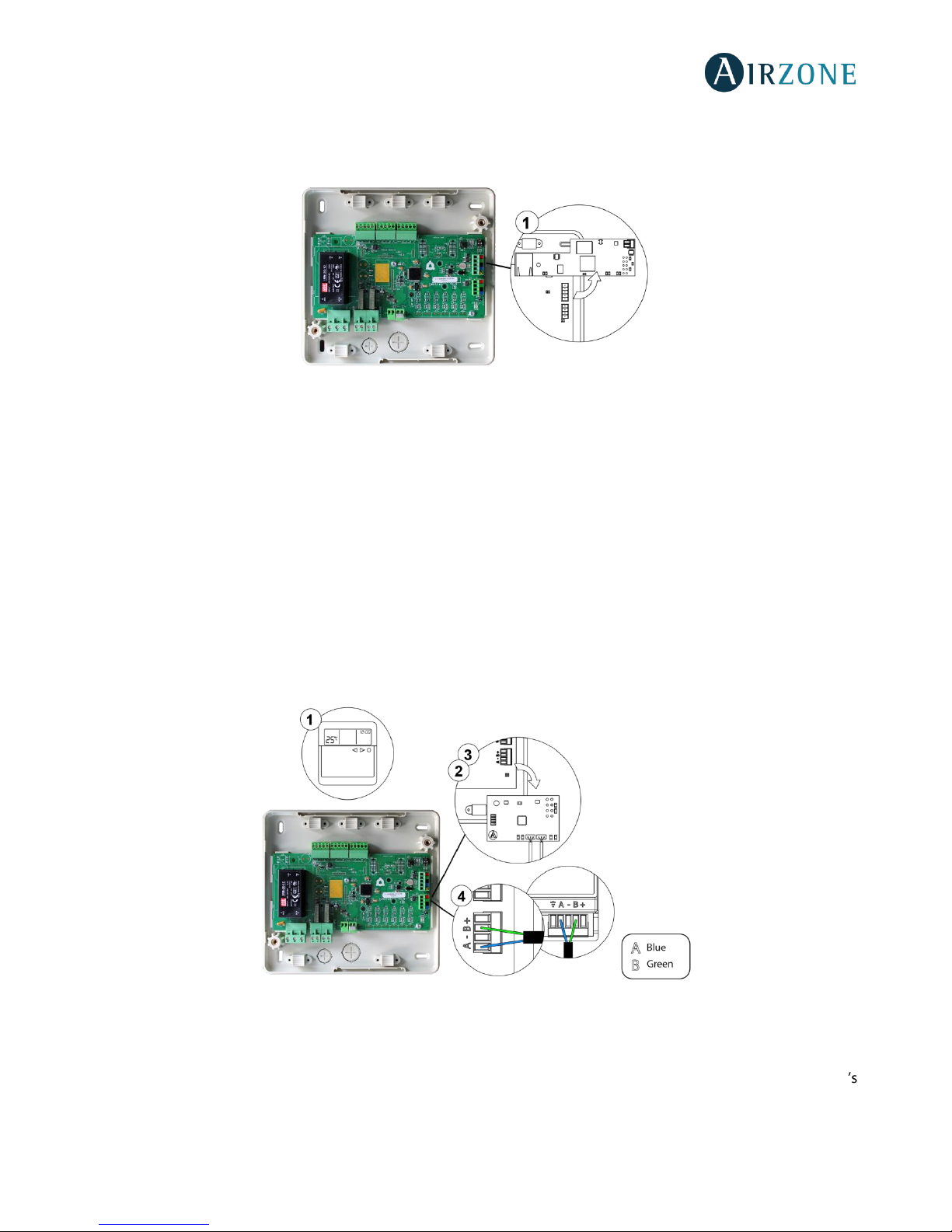
53
Error 10: Communication error between the BACnet Integration Gateway and the system
The system loses communication with the Airzone BACnet interface. Check that the gateway is properly connected to the
automation bus of the Control board.
Fig. 69
Error 11: Communication error between communication gateway and AC Unit
The system loses communication with the gateway and, therefore, with the AC unit. The system will open all the zones and
deactivate the control from the thermostats, only allowing the operation of the unit from the thermostat of its manufacturer.
To solve this incident check:
1. Verify if the Air unit is powered. To do this, check the thermostat of the AC unit is ON.
2. Verify the AC unit operates properly by itself. To do this, disconnect the A/C unit Airzone system and select the unit
from the thermostat from the A/C unit.
3. Connection: Check the polarity and connection of the gateway connectors and the indoor unit. Consult the technical
sheet of the gateway in question.
4. Wiring: In DIN-rail gateways, check that the voltage between the poles (A/ -) and (B/ -) is correct (0.65 Vdc).
5. Verify the status of the LEDs of the gateway is correct. To do this check the self-diagnose section or the technical sheet
of the gateway.
Fig. 70
Error 12: Communication error between Airzone Cloud Webserver and the system
The system loses communication with the Webserver. Check that the Webserver is correctly connected to the Control board
automation bus.
Page 54
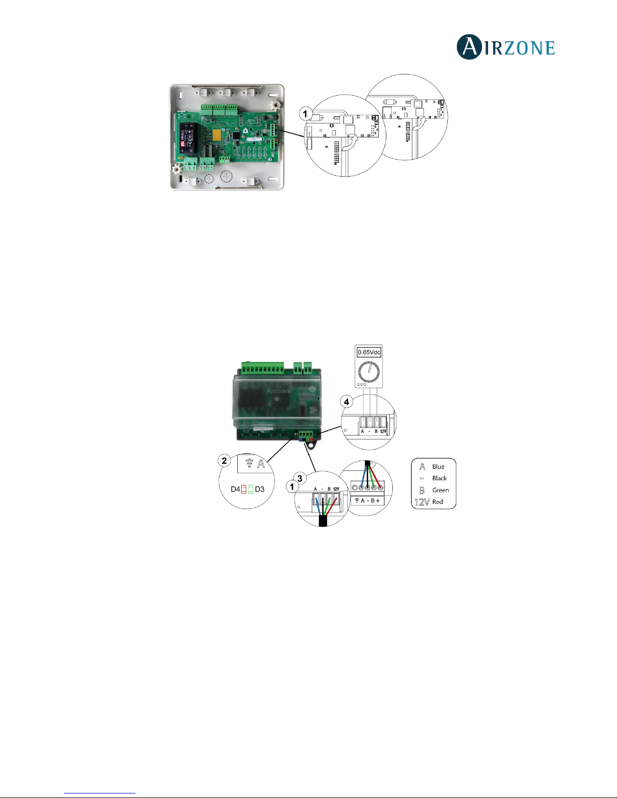
54
Fig. 71
Error 13: Communication error between Control board and Relay Radiant Heat Control Module
The device cannot be controlled by the system. To solve this incident check:
1. Status of the module: Correctly powered.
2. Status of the module and the control board: Airzone connection bus LEDs are operating properly.
3. Connection: Check the polarity of the connectors of the control board and the module.
4. Wiring: Check that the voltage between the poles (A /-) and (B/-) is about 0.65 Vdc.
Fig. 72
AC unit error: Error in the AC unit
Check the type of error in the AC unit thermostat and follow the instructions provided by the manufacturer.
Page 55
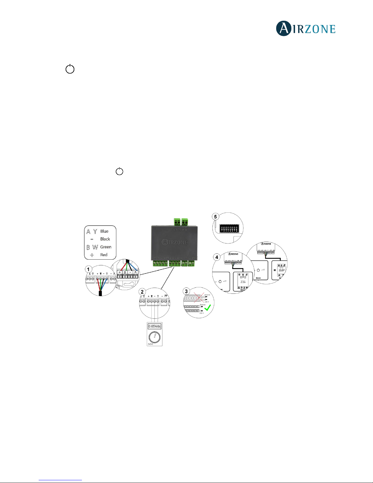
55
LITE THERMOSTATS (AZVAFLITE [C/R])
Lite thermostats incorporate LEDs that detect malfunctioning.
Status LED blinking purple quickly: Wired Lite Thermostat- Zone module communication error
(AZVAFDAMPERxxC / AZVAFZMRADC / AZVAFZMxxxC)
This incident blocks the control of the zone. To solve this incident check:
1. Connection: Check the polarity of the connectors of the module and the thermostat.
2. Wiring: Check that the voltage between the poles (A /-) and (B/-) is about 0.65 Vdc.
3. Wiring: Verify that the module connection bus-thermostat is not next to low-voltage wiring.
4. Module: Check the correct operation of the module, for this connect another thermostat and verify that Error 1 does
not appear on the screen.
5. Restart the zone and re-associate it with the system.
Remember: To reset to factory values of any Lite thermostat, turn up the microswitch 8 and place the thermostat on
the base again. Press on , the LED will flash green twice when the reset process is completed.
6. Restart system: If the system is restarted, this error may be displayed in the thermostats at the beginning of the process.
This message should disappear after around 30 seconds.
AZVAFDAMPERxxC / AZVAFZMRADC
Fig. 73
Page 56
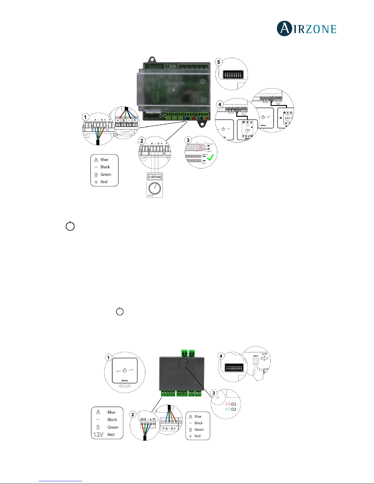
56
AZVAFZMxxxC
Fig. 74
Status LED blinking purple quickly: Wireless Lite Thermostat- Zone Module communication error
(AZVAFDAMPERxxR / AZVAFZMRADR / AZVAFZMxxxR)
This incident blocks the control of the zone. To solve this incident check:
1. Thermostat status: Check the signal range of the thermostat with the module through the Information parameter from
remote zones or approach the thermostat to the module if the thermostat recovers the communication, it is necessary
to relocate it as it was out of range.
2. Module status: Correctly powered.
3. Module status: Proper operation of the LED of wireless communication.
4. Restart the zone and re-associate it with the system.
Remember: To reset to factory values of any Lite thermostat, turn up the microswitch 8 and place the thermostat on
the base again. Press on , the LED will flash green twice when the reset process is completed.
5. Restart system: If the system is restarted, this error may be displayed in the thermostats at the beginning of the process.
This message should disappear after around 30 seconds.
AZVAFDAMPERxxR / AZVAFZMRADR
Fig. 75
Page 57
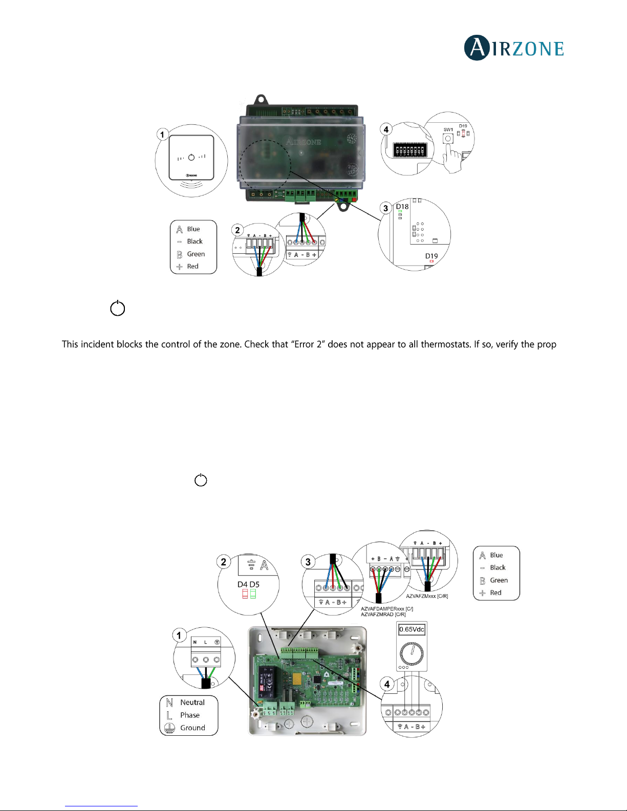
57
AZVAFZMxxxR
Fig. 76
Status LED blinking red quickly: Zone Module- Control board communication error (AZVAFDAMPERxx [C/R] /
AZVAFZMRAD [C/R] / AZVAFZMxxx [C/R])
er
operation of the main board. To solve this incident check:
1. Control board status: Correctly powered.
2. Control board status: Airzone Connection Bus LEDs are operating properly.
3. Connection: Verify the polarity of the control board and thermostat connectors.
4. Wiring: Check that the voltage between the poles (A /-) and (B/-) is about 0.65 Vdc.
5. Restart the zone and re-associate it with the system.
Remember: To reset to factory values of any Lite thermostat, turn up the microswitch 8 and place the thermostat on
the base again. Press on , the LED will flash green twice when the reset process is completed.
6. Restart system: If the system is restarted, this error may be displayed in the thermostats at the beginning of the process.
This message should disappear after around 30 seconds.
Fig. 77
Page 58
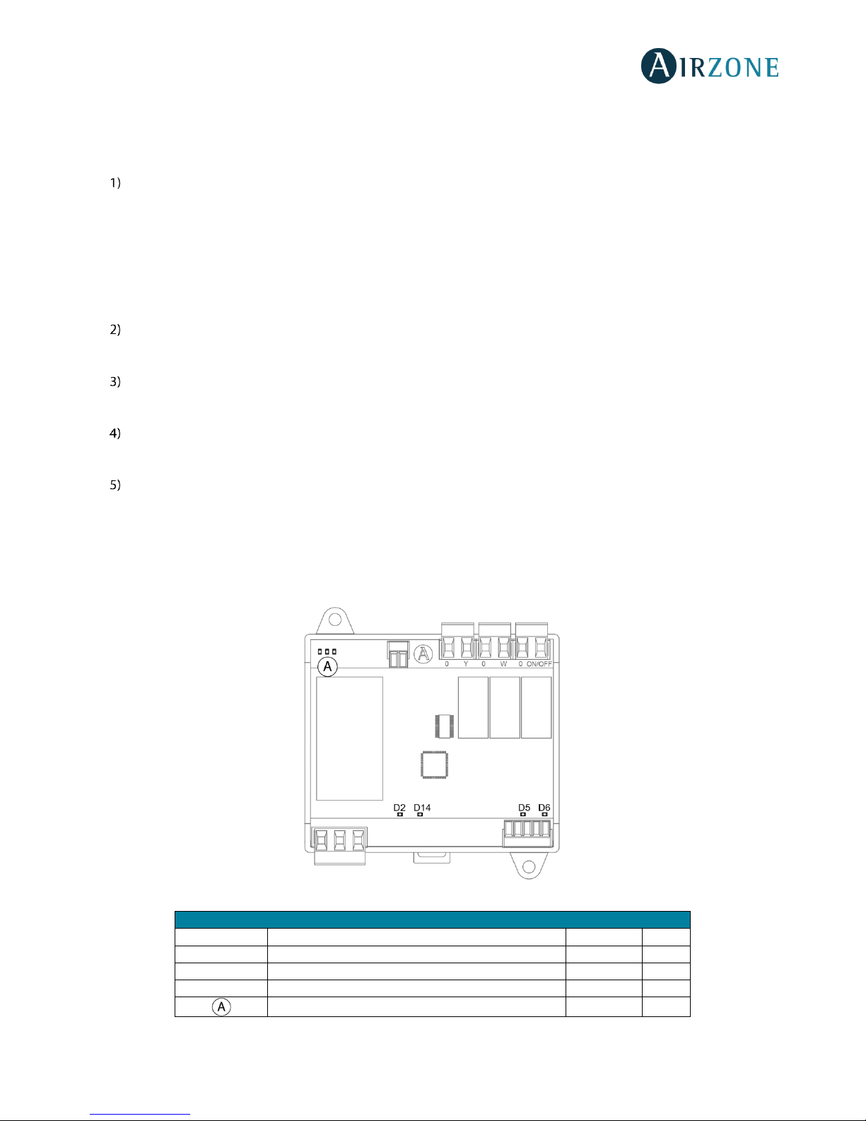
58
COMMUNICATION GATEWAYS (AZVAFGTXXX)
The communication gateways incorporate LEDs that detect unusual operations.
Check the distribution of the LEDs in the data sheet supplied along with the product.
Power LED D1: Off
• Check the air conditioning unit is powered.
• Check the connections between the gateway and the AC unit and between the gateway and the thermostat of the AC
unit (if applicable).
• Verify the status of the connectors in the wiring connecting gateway-AC unit and/or gateway-AC thermostat.
• Verify the gateway is properly connected to the AC unit port of the control board.
Microprocessor operation LED D2: Not blinking
• Contact the Airzone after-sales department, the microcontroller does not operate properly.
Communication LEDs D3 and D4: Not blinking
• Verify the gateway is properly connected to the AC unit port of the control board.
LEDs D5 and D6 of communication with the indoor unit: Not blinking
• Check gateway-AC unit connection.
LEDs D7 and D8 of communication with the indoor unit: Not blinking
• Check the Gateway-AC unit thermostat connection.
0-10 V FANCOIL CONTROL GATEWAY (AZVAFGTF10)
Airzone 0-10 V Fancoil control gateways incorporate LEDs that detect malfunctions.
Fig. 78
Meaning
D2
Data reception from AC unit bus
Steady
Red
D5
Data reception from AC unit bus
Blinking
Green
D6
Data transmission from AC unit bus
Blinking
Red
D14
Gateway performance
Blinking
Green
LEDs of relay state
Blinking
Green
Page 59
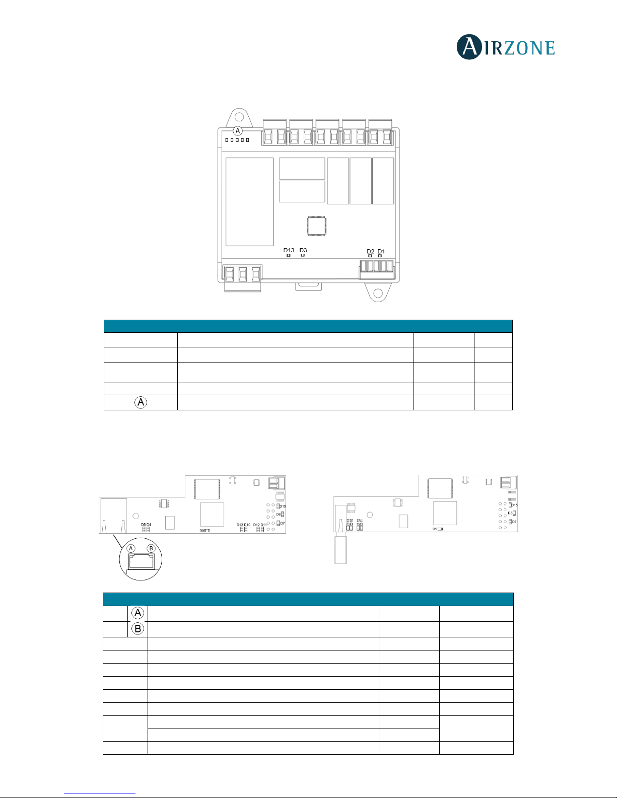
59
5-RELAY FANCOIL CONTROL GATEWAY (AZVAFGTF5R)
The 5-Relays Fancoil control gateways incorporate LEDs that detect malfunctions.
Fig. 79
ETHERNET/WIFI CLOUD WEBSERVER (AZVAFWSCLOUD [C/R])
Airzone Cloud Webservers incorporate LEDs that detect malfunctioning.
Meaning
D1
Data reception from AC unit bus
Blinking
Green
D2
Data transmission from AC unit bus
Blinking
Red
D3
Gateway performance
Blinking
Green
D5
Power supply
Steady
Red
LEDs of relay state
Blinking
Green
Fig. 80
AZVAFWSCLOUDC
AZVAFWSCLOUDR
Meaning
D5
Ethernet connected
Blinking
Green
D4
Ethernet activity
Blinking
Yellow / Red
D7
Data transmission from domotic bus (input and output)
Blinking
Red
D8
Data reception from domotic bus (input and output)
Blinking
Green
D9
Microswitch performance
Blinking
Green
D10
Connected to the Internet
Blinking
Green
D11
Network data transmission
Blinking
Red
D12
Network data reception
Blinking
Green
D13
Configured as IP address through DHCP
On
Red
Configured as Fixed IP address
Off
D15
Power supply
Steady
Red
Page 60
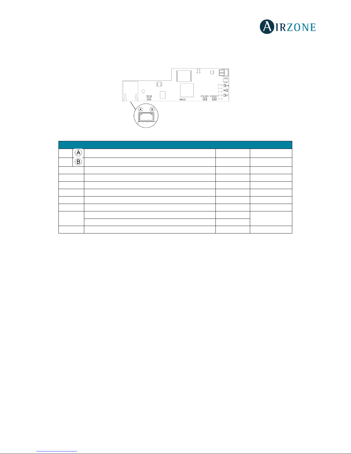
60
BACNET INTEGRATION GATEWAY (AZVAFBACNETG)
BACnet integration gateways incorporate LEDs that detect malfunctions.
Fig. 81
Meaning
D5
Ethernet connected
Blinking
Green
D4
Ethernet activity
Blinking
Yellow / Red
D7
Data transmission from automation
Blinking
Red
D8
Data reception from automation bus
Blinking
Green
D9
Microswitch performance
Blinking
Green
D10
Connected to the Internet
Blinking
Green
D11
Network data transmission
Blinking
Red
D12
Network data reception
Blinking
Green
D13
Configured as IP address through DHCP
On
Red
Configured as Fixed IP address
Off
D15
Power supply
Steady
Red
Page 61
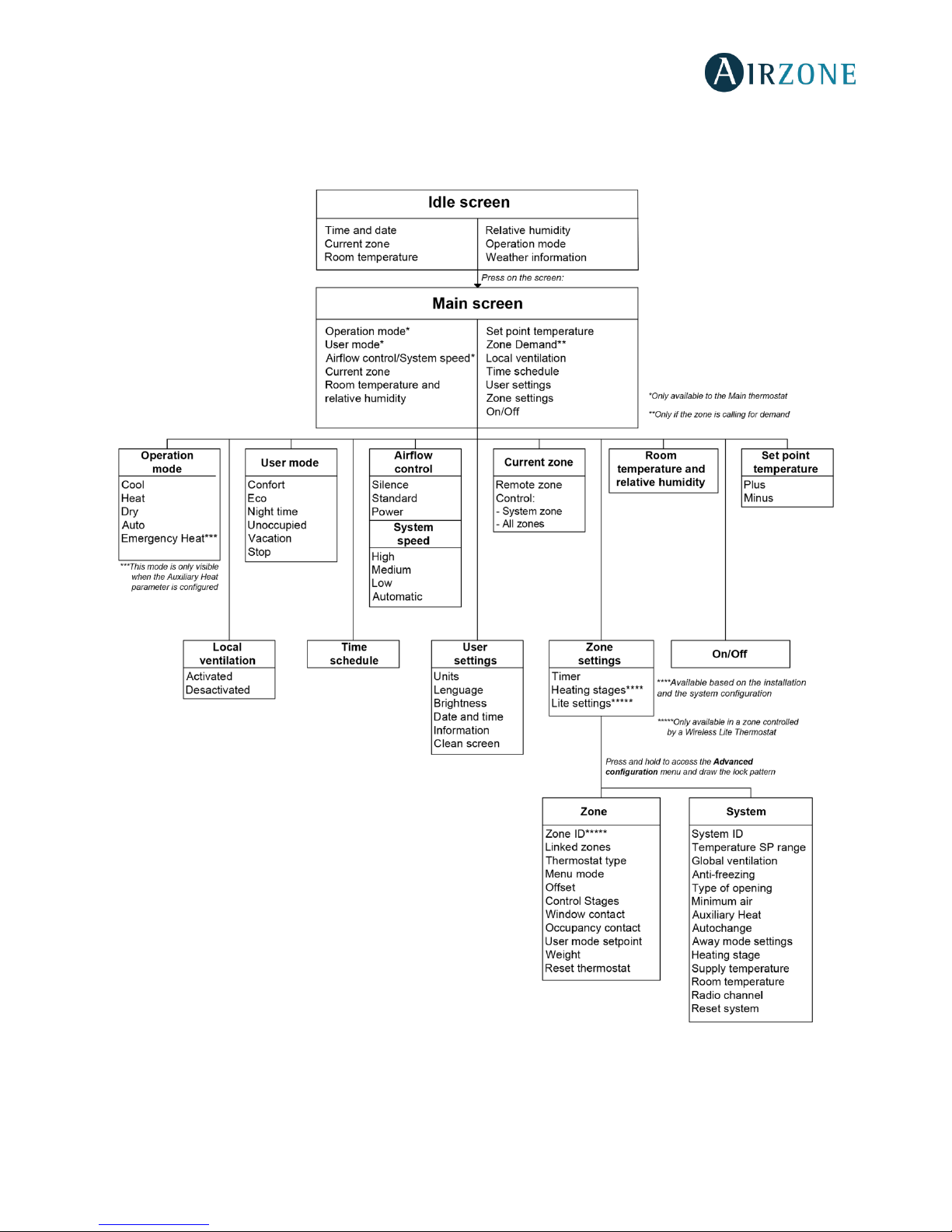
61
NAVIGATION TREES
BLUEFACE THERMOSTAT NAVIGATION TREE
Page 62
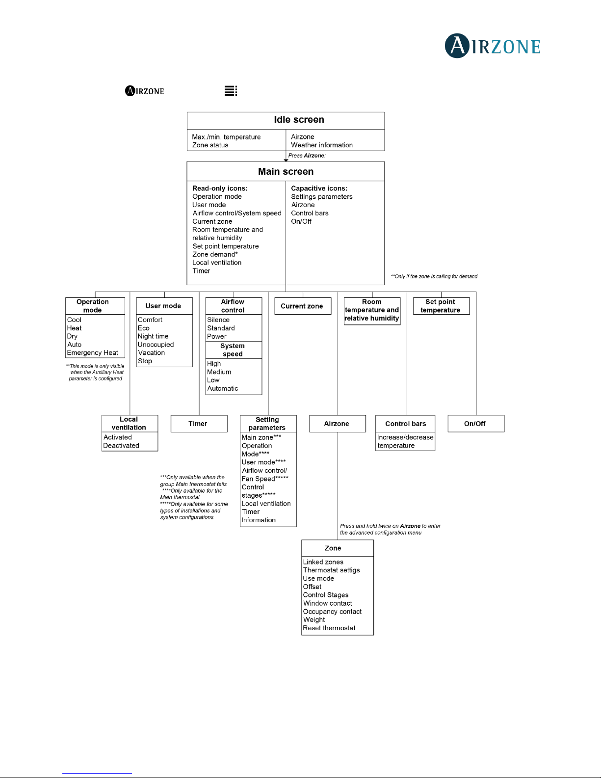
62
THINK THERMOSTAT NAVIGATION TREE
Remember: Use to confirm and for going back if browsing submenus.
Page 63
Parque Tecnológico de Andalucía
C/ Marie Curie, 21 29590
Campanillas Málaga - España
Phone: +34 902 400 445
Fax: +34 902 400 446
http://www.myzone.airzoneusa.com
 Loading...