

Page 1

TM
Network User Guide
Page 2

© 2000 Home Wireless Networks, Inc. All rights reserved.
AirWay™ Network User Guide
Part Number 84-0032-000 A0100
Home Wireless Networks, Inc.
3145 Avalon Ridge Place, Suite 200
Norcross, Georgia 30071-1582
The information in this manual is subject to change without
notice and should not be construed as a commitment by Home
Wireless Networks. Home Wireless Networks assumes no
responsibility or liability for any errors or inaccuracies that
may appear in this document.
The contents of this manual are the property of Home Wireless
Networks, Inc. and are copy righted. Any rep roduction in wh ole
or in part is strictly prohibited.
AirWay is a trademark of Home Wireless Networks, Inc.
Windows
®
is a registered trademark of Microsoft® Corporation.
Page 3

Contents
Introduction . . . . . . . . . . . . . . . . . . . . . . . . . . . . . . . . . . . . . . . . . . . . . 7
About This Manual . . . . . . . . . . . . . . . . . . . . . . . . . . . . . . . . . . . . . . 7
Getting Help. . . . . . . . . . . . . . . . . . . . . . . . . . . . . . . . . . . . . . . . . . . . 8
Safety Instructions. . . . . . . . . . . . . . . . . . . . . . . . . . . . . . . . . . . . . . . 8
Before You Begin . . . . . . . . . . . . . . . . . . . . . . . . . . . . . . . . . . . . . . . . 11
About Your AirWay System . . . . . . . . . . . . . . . . . . . . . . . . . . . . . . 11
System components. . . . . . . . . . . . . . . . . . . . . . . . . . . . . . . . . . . 13
Installation Sequence. . . . . . . . . . . . . . . . . . . . . . . . . . . . . . . . . . . . 14
Checking Parts. . . . . . . . . . . . . . . . . . . . . . . . . . . . . . . . . . . . . . . . . 15
About Your Controller Password . . . . . . . . . . . . . . . . . . . . . . . . . . 16
HandSet Battery Recycling Instructions . . . . . . . . . . . . . . . . . . . . . 16
Installing the Controller . . . . . . . . . . . . . . . . . . . . . . . . . . . . . . . . . . 17
Getting Started. . . . . . . . . . . . . . . . . . . . . . . . . . . . . . . . . . . . . . . . . 17
Connecting Your Phone Lines. . . . . . . . . . . . . . . . . . . . . . . . . . . . . 21
Connecting the AirWay 308 without External Modem. . . . . . . . 22
Connecting the AirWay 308 and External Modem. . . . . . . . . . . 24
Connecting the AirWay 516 without External Modem. . . . . . . . 28
Connecting the AirWay 516 and External Modem. . . . . . . . . . . 30
Installing the Battery . . . . . . . . . . . . . . . . . . . . . . . . . . . . . . . . . . . . 34
Connecting the Power . . . . . . . . . . . . . . . . . . . . . . . . . . . . . . . . . . . 35
Installing HandSets . . . . . . . . . . . . . . . . . . . . . . . . . . . . . . . . . . . . . . 36
Preparing the Charging Cradle . . . . . . . . . . . . . . . . . . . . . . . . . . . . 36
Installing and Charging the Battery Pack . . . . . . . . . . . . . . . . . . . . 37
Registering a HandSet . . . . . . . . . . . . . . . . . . . . . . . . . . . . . . . . . . . 39
Installing DataJacks. . . . . . . . . . . . . . . . . . . . . . . . . . . . . . . . . . . . . . 42
Getting Started. . . . . . . . . . . . . . . . . . . . . . . . . . . . . . . . . . . . . . . . . 42
Connecting the DataJack . . . . . . . . . . . . . . . . . . . . . . . . . . . . . . . . . 45
Installing the DataJack Software . . . . . . . . . . . . . . . . . . . . . . . . . . . 45
Checking status of the comm link. . . . . . . . . . . . . . . . . . . . . . . . 48
Contents • 3
Page 4

Installing PhoneJacks . . . . . . . . . . . . . . . . . . . . . . . . . . . . . . . . . . . . 49
Getting Started. . . . . . . . . . . . . . . . . . . . . . . . . . . . . . . . . . . . . . . . . 49
Connecting the PhoneJack. . . . . . . . . . . . . . . . . . . . . . . . . . . . . . . . 50
Registering the PhoneJack. . . . . . . . . . . . . . . . . . . . . . . . . . . . . . . . 50
Configuring the Network For Use With PhoneJacks . . . . . . . . . . . 51
Using a PhoneJack with a fax machine. . . . . . . . . . . . . . . . . . . . 51
Using a PhoneJack with Caller ID/Call Waiting devices . . . . . . 52
Basic HandSet Operation . . . . . . . . . . . . . . . . . . . . . . . . . . . . . . . . . 53
About Your HandSet Screens . . . . . . . . . . . . . . . . . . . . . . . . . . . . . 53
The Idle Screen . . . . . . . . . . . . . . . . . . . . . . . . . . . . . . . . . . . . . . 53
The Line Status Screen . . . . . . . . . . . . . . . . . . . . . . . . . . . . . . . . 53
The Menu Screens. . . . . . . . . . . . . . . . . . . . . . . . . . . . . . . . . . . . 54
Using Your HandSet Features. . . . . . . . . . . . . . . . . . . . . . . . . . . . . 55
Basic Calling Features . . . . . . . . . . . . . . . . . . . . . . . . . . . . . . . . 55
Caller ID Features. . . . . . . . . . . . . . . . . . . . . . . . . . . . . . . . . . . . 58
Directory Features. . . . . . . . . . . . . . . . . . . . . . . . . . . . . . . . . . . . 60
Conference Calling Features. . . . . . . . . . . . . . . . . . . . . . . . . . . . 61
Miscellaneous General Features. . . . . . . . . . . . . . . . . . . . . . . . . 62
Sharing Data Network Resources . . . . . . . . . . . . . . . . . . . . . . . . . . 64
Sharing Files . . . . . . . . . . . . . . . . . . . . . . . . . . . . . . . . . . . . . . . . . . 64
Sharing Printers. . . . . . . . . . . . . . . . . . . . . . . . . . . . . . . . . . . . . . . . 66
Sharing an Internet Connection. . . . . . . . . . . . . . . . . . . . . . . . . . . . 67
Configuring your computer to connect via the AirWay LAN . . 67
Accessing the Internet. . . . . . . . . . . . . . . . . . . . . . . . . . . . . . . . . 70
Modifying Your Voice Network Settings. . . . . . . . . . . . . . . . . . . . . 72
General System Information . . . . . . . . . . . . . . . . . . . . . . . . . . . . . . 73
Setting the time and date. . . . . . . . . . . . . . . . . . . . . . . . . . . . . . . 73
Verifying the system software version . . . . . . . . . . . . . . . . . . . . 73
Changing the Controller password . . . . . . . . . . . . . . . . . . . . . . . 74
Managing Network Devices . . . . . . . . . . . . . . . . . . . . . . . . . . . . . . 75
Adding HandSets and PhoneJacks to the network . . . . . . . . . . . 75
Removing Devices from the network. . . . . . . . . . . . . . . . . . . . . 76
Changing a device name. . . . . . . . . . . . . . . . . . . . . . . . . . . . . . . 77
Setting outbound line selection options . . . . . . . . . . . . . . . . . . . 78
Setting inbound ringing options . . . . . . . . . . . . . . . . . . . . . . . . . 79
Turning Call Waiting Deluxe on/off for PhoneJacks . . . . . . . . . 80
4•Contents
Page 5

Setting Phone Line Options. . . . . . . . . . . . . . . . . . . . . . . . . . . . . . . 81
Setting the Line Call Forwarding option. . . . . . . . . . . . . . . . . . . 81
Setting the Line Call Privacy option . . . . . . . . . . . . . . . . . . . . . . 82
Setting Ring Patterns. . . . . . . . . . . . . . . . . . . . . . . . . . . . . . . . . . 82
Setting System Timers. . . . . . . . . . . . . . . . . . . . . . . . . . . . . . . . . . . 83
Setting the Hold Recall Timer. . . . . . . . . . . . . . . . . . . . . . . . . . . 83
Setting the Transfer Recall Timer. . . . . . . . . . . . . . . . . . . . . . . . 84
Setting the Call Forward Disconnect Timer . . . . . . . . . . . . . . . . 84
Using Voice Mail. . . . . . . . . . . . . . . . . . . . . . . . . . . . . . . . . . . . . . . 85
Turning Voice Mail On and Off . . . . . . . . . . . . . . . . . . . . . . . . . 85
Modifying Your Data Network Settings . . . . . . . . . . . . . . . . . . . . . 86
Changing Controllers. . . . . . . . . . . . . . . . . . . . . . . . . . . . . . . . . . . . 86
Installing a new controller on your computer . . . . . . . . . . . . . . . 86
Selecting a different installed Controller. . . . . . . . . . . . . . . . . . . 87
Changing Your Computer’s Network Name. . . . . . . . . . . . . . . . . . 87
Modifying External Modem Settings . . . . . . . . . . . . . . . . . . . . . . . 88
About ISP profiles. . . . . . . . . . . . . . . . . . . . . . . . . . . . . . . . . . . . 88
Changing the modem type. . . . . . . . . . . . . . . . . . . . . . . . . . . . . . 90
Modifying the modem’s dialing properties. . . . . . . . . . . . . . . . . 90
Upgrading Your System Software . . . . . . . . . . . . . . . . . . . . . . . . . . 91
Troubleshooting . . . . . . . . . . . . . . . . . . . . . . . . . . . . . . . . . . . . . . . . . 94
General network questions . . . . . . . . . . . . . . . . . . . . . . . . . . . . . 94
HandSet questions. . . . . . . . . . . . . . . . . . . . . . . . . . . . . . . . . . . . 95
DataJack questions . . . . . . . . . . . . . . . . . . . . . . . . . . . . . . . . . . . 97
PhoneJack questions . . . . . . . . . . . . . . . . . . . . . . . . . . . . . . . . . 101
Frequently Asked Questions. . . . . . . . . . . . . . . . . . . . . . . . . . . . . . 102
About AirWay products in general . . . . . . . . . . . . . . . . . . . . . . 102
About the HandSet . . . . . . . . . . . . . . . . . . . . . . . . . . . . . . . . . . 106
About the PhoneJack. . . . . . . . . . . . . . . . . . . . . . . . . . . . . . . . . 109
About Software Features of your AirWay System . . . . . . . . . . 109
Appendix. . . . . . . . . . . . . . . . . . . . . . . . . . . . . . . . . . . . . . . . . . . . . . 111
Specifications. . . . . . . . . . . . . . . . . . . . . . . . . . . . . . . . . . . . . . . . . 111
Regulatory Statements. . . . . . . . . . . . . . . . . . . . . . . . . . . . . . . . . . 114
Contents • 5
Page 6

United States. . . . . . . . . . . . . . . . . . . . . . . . . . . . . . . . . . . . . . . 114
Canada. . . . . . . . . . . . . . . . . . . . . . . . . . . . . . . . . . . . . . . . . . . . 116
Warranty & Limitation of Liability. . . . . . . . . . . . . . . . . . . . . . . . 118
Wall Mounting Instructions. . . . . . . . . . . . . . . . . . . . . . . . . . . . . . 121
Mounting the Controller on a wall . . . . . . . . . . . . . . . . . . . . . . 121
Mounting the HandSet charging cradle on a wall. . . . . . . . . . . 122
6•Contents
Page 7

Introduction
About This Manual
This Network User Guide is designed to provide detailed
information on installing and using your AirWay system. It
contains the following sections:
■ Before You Begin - an introduction to your AirWay system,
information about product docume ntation, how to get help,
safety precautions, and so on.
■ Setting Up Your Network - detailed instructions for installing
your network components.
■ Basic HandSet Operation - commonly used HandSet features
■ Sharing Data Network Resources - how to set up and use
shared files, printers, and internet connections among network
computers
■ Modifying Your Voice Network Settings - how to set phone
line and extension options, change Controller password, etc.
■ Modifying Your Data Network Settings - how to register a
DataJack on a different Controller, change your computer’s
network name, and modify settings for an Internet Gateway
modem connected to the Controller.
■ Upgrading Your System Software - how to do wn load new soft-
ware for your AirWay system from a HandSet
■ Troubles ho ot ing and Frequently-Asked Questions
■ Specifications, Regulatory Statements, and Warranty & Return
Instructions
Introduction • 7
Page 8

Getting Help
If you need help installing or using your AirWay system, you can
refer to the following resources:
■ The Troubleshooting section in this manual.
■ Toll-free Telephone Support - call 1-888-WHY-WIRE (949-
9473).
■ Internet Support - go to AirWaySystem.com.
Safety Instructions
When using your telephone equipment, basic safety precautions
should always be followed to reduce the risk of fire, electric shock,
and injury.
1. Read and understand all instructions.
2. Follo w all warnings and instructions marked on the product.
3. Do not use this product near water or when you are wet (for
example, near a bath tub, kitchen sink, lau ndry tub, wash bo wl,
wet basement, or swimming pool). Unplug this product from
the wall outlet before cleaning. Do not use liquid cleaners or
aerosol cleaners. Use a damp cloth for cleaning. Do not plug
the product back in until it is thoroughly dry.
4. Avoid using a telephone (other than a cordless one) during an
electrical storm. There may be a remote risk of electric shock.
5. Do not use a telephone in the vicinity of a gas leak. If you
suspect a gas leak, report it immediately using a telephone
located away from the area where the gas is leaking. Also
make sure the Controller unit is located away from the area of
the suspected leak.
6. This product should be operated only from the type of power
source indicated on the marking label. If you are not sure o f the
type of power that is supplied to your location, consult your
dealer or local power company.
7. Do not overload the wall outlets or extension cords as this can
result in the risk of fire or electric shock.
8 • Introduction
Page 9

8. Do not allow anything to rest on the power cord. Do not locate
this product where the cord will be abused by people walking
on it.
9. This product must not be installed in an attic, garage or other
temperature-extreme environment.
10. To reduce the risk of electric shock, do not disassemble the
telephone equipment. Opening or removi ng covers may expose
you to dangerous voltages or other risks. Incorrect reassembly
could cause electric shock. If service or repair work is required,
take the unit to a qualified technician.
11. Unplug this product from the wall outlet and refer servicing to
qualified service personnel under the follow ing conditions:
• The power cord is damaged or frayed.
• Liquid has been spilled into th e product.
• The product has been exposed to rain or water.
• The product has been dropped or the enclosure has been
damaged.
• The product exhibits a distinct change in performance.
• The product does not operate normally by following the
operating instructions.
Use with medical devices
This device operates in the frequency range of 902-928 MHz and
has a power output level th at ranges from 0.001 to 0.10 watts.
Before installing and using the device in a locatio n where personal
medical devices such as pacemakers, etc., are in use, consult the
manufacturer of the medical device to determine if it is adequately
shielded from external RF (radio frequency) energy in the indicated
range. Do not use this unit in health-care facilities when regulations
posted in the area so indicate. Hospitals or health-care facilities
may be using equipment that could be sensitive to external RF
(radio frequency) energy.
Introduction • 9
Page 10

Battery cautions
To reduce the risk of fire or injury to persons caused by batteries,
read and follow these instructions.
1. Use only the proper type and size batteries.
2. Do not dispose of batteries in a fire. The cell may explode.
Check with local codes for possible special disposal
instructions. See page16 for information on recycling spent
HandSet batteries.
3. Do not open or mutilate the battery. Released electrolyte is
corrosive and may cause damage to eyes or skin. It may be
toxic if swallowed.
4. Exercise care in handling the battery in order not to short the
battery with conducting materials such as rings, bracelets, and
keys. The battery or conductor may overheat and cause burns.
5. Charge the Hand Set battery pack provided with or identified
for use with this product only in accordance with the
instructions and limitations specified for this product.
6. Observe proper polarity orientation when installing batteries.
Preventing static electricity damage
The components inside your system are extremely sensitive to
static electricity, also known as electro-static discharge (ESD).
Static electricity can cause irreparable damage to your system. You
can help prevent such damage by taking the following precautions:
■ Avoid touching expansion slot connectors.
■ A v oid placing static-causing surfaces such as p lastic and Styro-
foam near your unit.
■ Avoid sliding the unit across any surface.
10 • Introduction
Page 11

Before You Begin
About Your AirWay System
Your AirWay wireless communication system is the world’s first
wireless networking product designed to provide both voice and
data networking capabilities to the h ome and small business.
No addtitional wires to run!
The AirWay system allows you to easily build a wireless network
that includes desktop and laptop computers, AirWay wireless
HandSets, and standard analog devices such as wired telephones
and fax machines, without the hassle and expense of running
additional phone lines or data cables throughout your building.
Because the networked devices are connected together wirelessly,
you can move them virtually anywhere within your premises,
anytime you wish, again without having to rewire your building.
Share all phone lines among all network devices!
Your AirWay system allows you to share all your phone lines
among all network devices, so you can pick up incoming calls or
place outgoing calls on any line from any phone in the network.
Because the AirWay system is so flexible, you can also easily
configure it to restrict a line to a particular extension or extensio ns.
Share computer data, peripherals, and Internet accounts!
Not only can you share files and peripherals such as printers and
modems among networked computers, but your AirWay system
also allows all computer users in the network to share a single
Internet account - all at the same time.
Advanced telephone features on a wireless HandSet!
Besides offering the convenience and portability of a wireless
telephone, your AirWay HandSet also provides such advanced
telephone features as multi-line call handling with Caller ID,
conference calling, extension-to-extension calling, call transfer , and
speed dialing using custom dialing directories.
Before You Begin • 11
Page 12

Secure communications!
Your AirWay system uses Digital Spread Spectrum Technology to
help ensure robust, secure communications. The system provides
five levels of security, the highest available for 900 MHz products.
The first level of security involves peripheral registration and
authentication. All network devices must be registered with the
Controller using a unique Controller ID number and system
password. In addition, network devices must continually reauthenticate themselves to the Controller during communications.
This authentication process takes place automatically, with no
action required by the user.
Other security measures involve a unique, seven-layer call
processing protocol in which all calls are authorized, digitized,
scrambled, and dynamically rephased before transmission to help
ensure privacy from eavesdropping.
Additional Features
■ Supports multiple phone lines
• AirWa y 516 - up to five telephone lines (four for voice,
fax, etc., and one for Internet access via external modem)
• AirWa y 308 - up to three telephone lines (two for voice,
fax, etc., and one for Internet access via external modem)
■ Supports multiple network peripherals (16 for AirWay 516, 8
for AirWay 308)
■ Interoperates with existing inside wiring
■ Windows® compatibility allows computers to be easily con-
nected to network
■ Easy system administration from AirWay HandSets
■ Low Battery & Out of Range warnings on HandSet
12 • Before You Begin
Page 13
System components
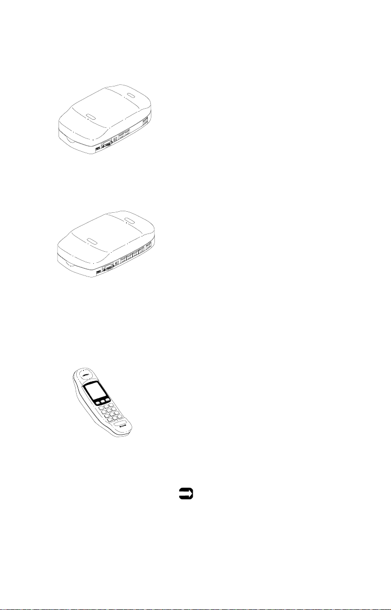
AirWay 308 Controller
AirWay 516 Controller
Controller
The Controller is the primary component of
your AirWay system. It connects to your
incoming telephone lines and controls all
communications between devices on the network.
When connected to an external modem, the
Controller also performs as an Internet gateway to allow network computers to simultaneously access the same Internet account.
HandSet
The AirWay HandSet is a sophisticated wireless telephone. It provides many features
found only on lar g e r, business telephone sets,
such as line status screen, Caller ID display
and log, call conferencing, call forwarding,
call transfer, call privacy and muting, custom
dialing directory, and extension-to-extension
dialing. In addition, the HandSet can be used
for system administration of your AirWay
network.
Note:
Caller ID features require subscription with
your telephone company.
Before You Begin • 13
Page 14
Installation Sequence
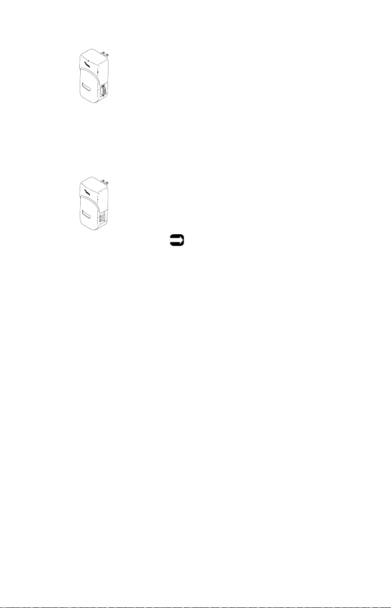
DataJack
The AirWay DataJack allows you to wirelessly add a desktop or laptop computer to
your network. By adding several computers
to the network, you can build a wireless Local
Area Network (LAN) that allows you to share
files, peripherals such as printers, scanners,
etc., as well as Internet accounts among the
networked computer s.
PhoneJack
The AirWay PhoneJack allows you to wirelessly add analog devices such as FAX
machines, standard wired telephones, and
answering machines to your network.
Note:
PhoneJacks are not included in the AirWay
Starter Kit.
Network components must be installed in the following order:
1. Controller
2. HandSet
3. DataJack
4. PhoneJack (not included in AirWay Starter Kit)
14 • Before You Begin
Page 15

Checking Parts
Your AirWay Starter Kit contains the following items:
■ Controller (1) & accessories
• AC adapter & power cord
• 9v alkaline battery
• 6’ RJ14 phone cable(s) - on e wit h AirWay 308 Controller,
two with AirWay 516 Controller
• Sheet of self-adhesive protective feet
■ HandSet (1) & accessories
• HandSet Charging Cradle
• AC Adapter & power cord
• NiCad Battery Pack
• Sheet of self-adhesive protective feet and phone number
form with plastic cover
■ DataJack (1) & accessories
• 6’ Serial Cable (9-pin)
• DataJack software (on CD)
■ User Documentation
• Fold-out Quick Start Installation Guide
• Network User Guide
• HandSet Quick Reference Card
• Product Registration Card
If any parts are missing or broken, contact your equipment
provider.
Before You Begin • 15
Page 16

About Your Controller Password
The Controller password prevents unauthorized individuals from
registering devices on your network. The default password is
“1234.” You should change this password to one of your own
choosing as soon as you have finished setting up your system. You
can change the password from any registered AirWay HandSet. For
more information on changing your system password, see
“Changing the Controller password” on page 74.
HandSet Battery Recycling Instructions
The EPA-certified RBRC® Battery
Recycling Seal on the Nickel-Cadmium
(NiCad) battery used in AirWay HandSets
indicates that Home Wireless Networks, Inc.,
is voluntarily participating in an industry
program to collect and recycle these batteries
at the end of their useful life, when taken out of service within the
United States and Canada. The RBRC® program provides a
convenient alternative to placing spent NiCad batteries into the
trash or municipal waste streams, which may be illegal in your area.
Please call 1-800-8-BATTERY™ for inf ormation on NiCad battery
recycling and disposal bans/restrictions in your area. Home
Wireless Networks’ involvement in this program is part of our
commitment to preserving our environment and conserving our
natural resources.
To order replacement HandSet batteries, call Home Wireless
Networks toll-free at 1-888-WHY-WIRE (949-94 73).
16 • Before You Begin
Page 17
Installing the Controller
Getting Started
Learning about your Controller
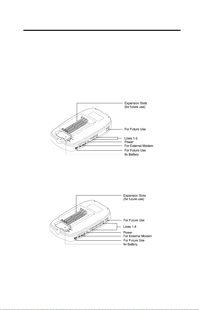
Refer to the following illustrations to become familiar with you r
AirWay Controller.
AirWay 308 Controller
AirWay 516 Controller
Installing the Controller • 17
Page 18

Choosing a location
Remember the following points when deciding where to install the
Controller.
■ To facilitate battery replacement, your Controller must be
placed in an easily-accessible location.
■ The Controller should be either wall-mounted or placed on a
stable horizontal surface such as a desk or countertop.
■ The Controller must be located within 6 feet of an electrical
outlet that is not controlled by a wall switch and within 6 feet
of a wall jack or jacks that terminate all the telephone lines you
wish to connect to it.
Note:
If there is no single location where all telephone lines are
present, you will need to reroute the lines so they have a
common entry point into the b uilding. Contact a qualified
telephone technician to arrange for this service.
Locations to avoid
Avoid placing the Controller in the following locations:
■ Attics, garages, or other temperature-extreme locations.
■ On top of or immediately adjacent to a TV, VCR, stereo
system, or computer.
■ Beside a window facing a street with heavy traffic.
■ Near heat sources such as radiators or air ducts, near a
microwave oven, or in direct sunlight.
■ Where it might be subject to water splash, dust, or mechanical
vibration.
■ Near large metal objects, such as metal shelving, etc.
18 • Installing the Controller
Page 19
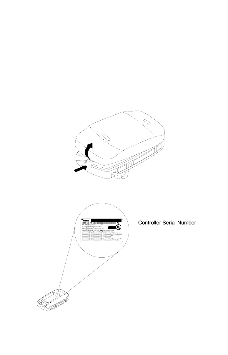
Recording the Controller serial number
Before you begin installing your Controller, record the unit’s serial
number in the space provided at the end of this manual. You will
need the last eight digits of the serial number when adding extra
HandSets and DataJacks to your network, and will need the full
serial number should you ever need to contact Technical Support
for your AirWay system.
The Controller serial number is located on the label beneath the
cover. See the following illustrations.
Installing the Controller • 19
Page 20
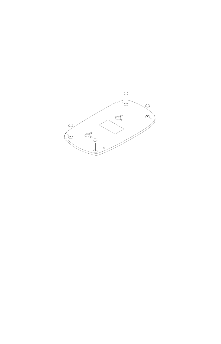
Attaching protective feet to Controller base
If you are placing the Controller on a horizontal surface such as a
desk or countertop, peel off the self-adhesive protective feet from
the included sheet and affix them to the underside of the Controller
as shown in the following illustration. (If you are wall-mounting the
Controller instead, refer to the wall-mounting instructions at the
end of this manual.)
.
20 • Installing the Controller
Page 21

Connecting Your Phone Lines
Determining the correct connection procedure
The line connection procedure varies depending on several factors,
including your Controller model (308 or 516), whether you have 2line or single-line wall jacks, whether or not you are installing an
external Internet Gateway modem, and if so, if the modem will use
a dedicated phone line or share a line with the Controller.
The following table will help you locate the correct procedu re for
your situation.
Controller
Model
308 No N/A 2-line 22
516 No N/A 2-line 28
Connecting
external modem
to Controller?
Yes No 2-line 24
Yes No 2-line 30
Modem &
Controller will
share phone line?
Yes 2-line 26
Yes 2-line 32
Telephone
single-line 23
single-line 25
single-line 27
single-line 29
single-line 31
single-line 33
Wiring
Type
See
page
Installing the Controller • 21
Page 22
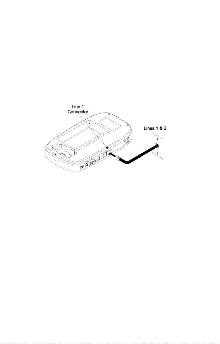
Connecting the AirWay 308 without External Modem
For two-line wall jacks
Connect a phone cable to the wall jack carrying your primary
1
incoming telephone lines (lines 1 and 2).
Plug the other end of the cable into the Line 1 connector on the
2
Controller. Be sure to leave the Line 2 connector empty.
Connecting the AirWay 308 Controller to 2-line wall
jacks if not installing an external modem
22 • Installing the Controller
Page 23
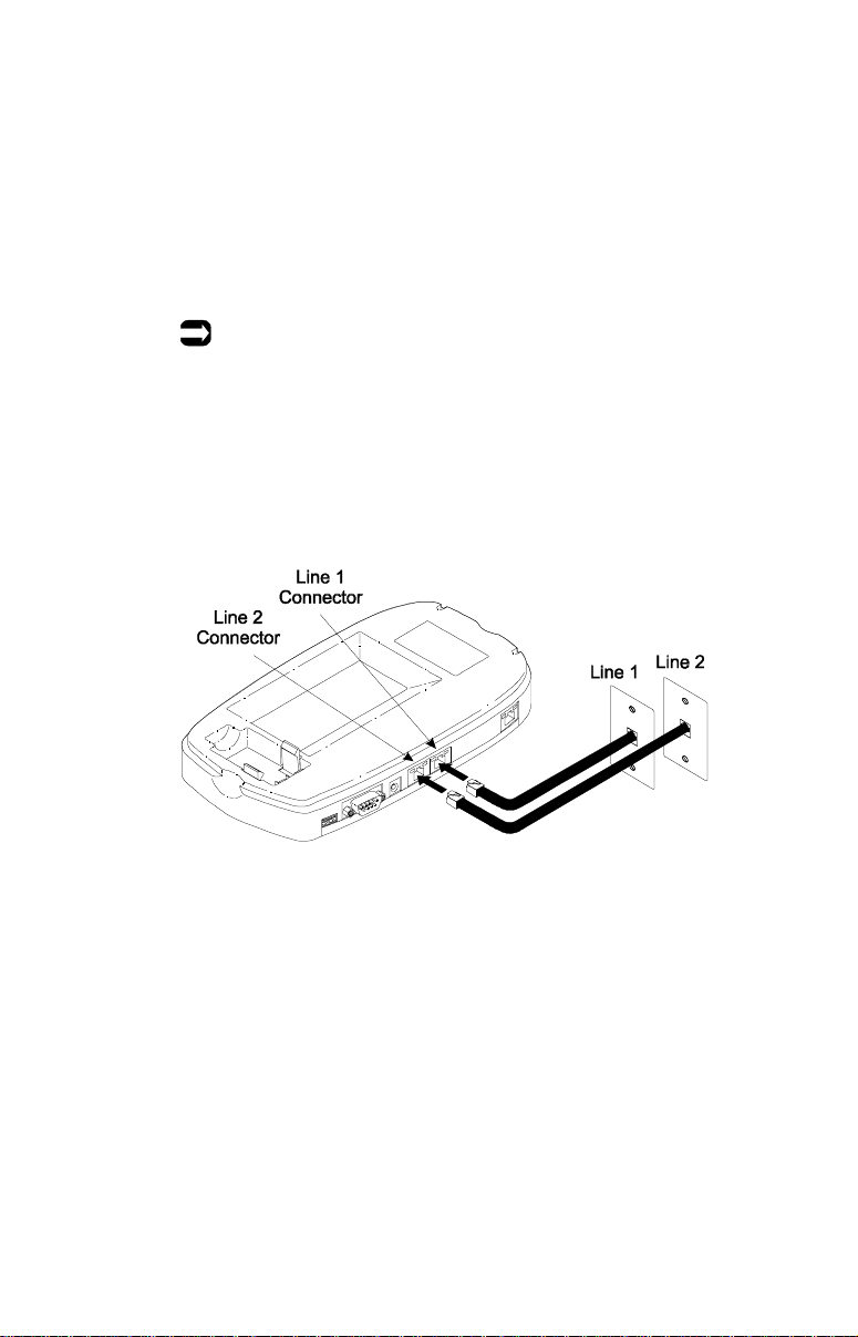
For single-line wall jacks
Connect a phone cable to the wall jack carrying your primary
1
incoming telephone line (line 1). Plug the other end of the
cable into the Line 1 connector on the Controller.
Connect a second phone cable to the wall jack carrying your
2
secondary telephone line (line 2). Plug the other end of the
cable into the Line 2 connector on the Controller.
Note:
The AirWay 308 Controller is packaged with one RJ14
telephone cable. If needed, you can ob tain additional phone
cables from your local telephone supply st or e.
Connecting the AirWay 308 Controller to single-line wall
jacks if not installing an external modem
Installing the Controller • 23
Page 24
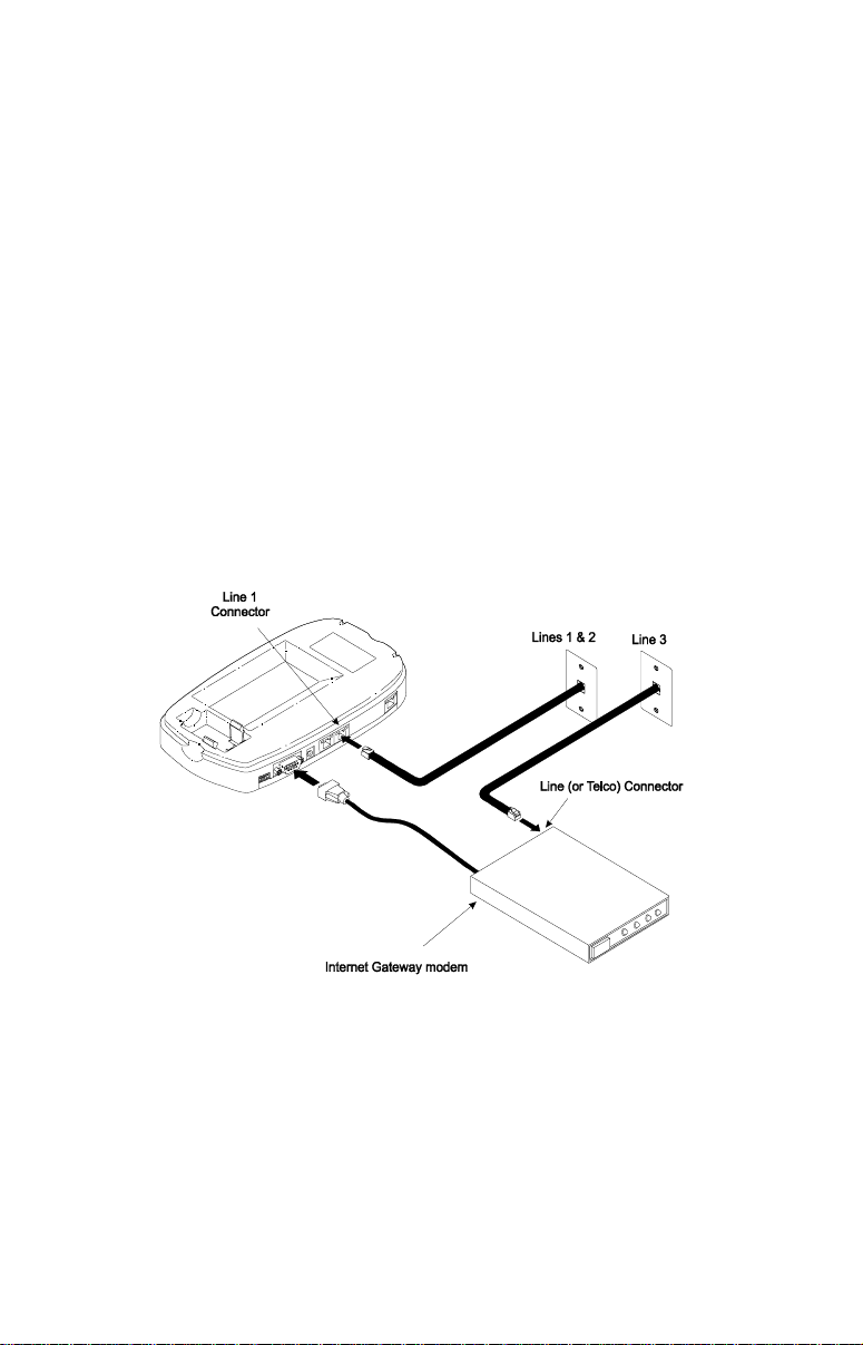
Connecting the AirWay 308 and External Modem
If external modem will use a dedicated phone line
For two-line wall jacks
Connect a phone cable to the wall jack carrying your primary
1
incoming telephone lines (lines 1 and 2). Plug the other end of
the cable into the Line 1 connector on the Controller. Be sure
to leave the Line 2 connector empty.
Connect a phone cable to th e wall jack carry ing your secondary
2
incoming phone lin e(s). Pl ug the other end of the cab le i nto the
Line (or Telco) connector on the modem.
Connect one end of the modem serial cable to the modem as
3
described in the modem’s user manual. Connect the other end
of the cable to the serial port on the Controller.
Connecting the AirWay 308 Controller to 2-line wall
jacks when installing an external modem using a
dedicated phone line
24 • Installing the Controller
Page 25
For single-line wall jacks
Connect a phone cable to the wall jack carrying your primary
1
incoming telephone line. Plug the other end of the cable into
the Line 1 connector on the Controller.
Connect a phone cable to th e wall jack carry ing your secondary
2
incoming telephone line. Plug the other end of the cable into
the Line 2 connector on the Controller.
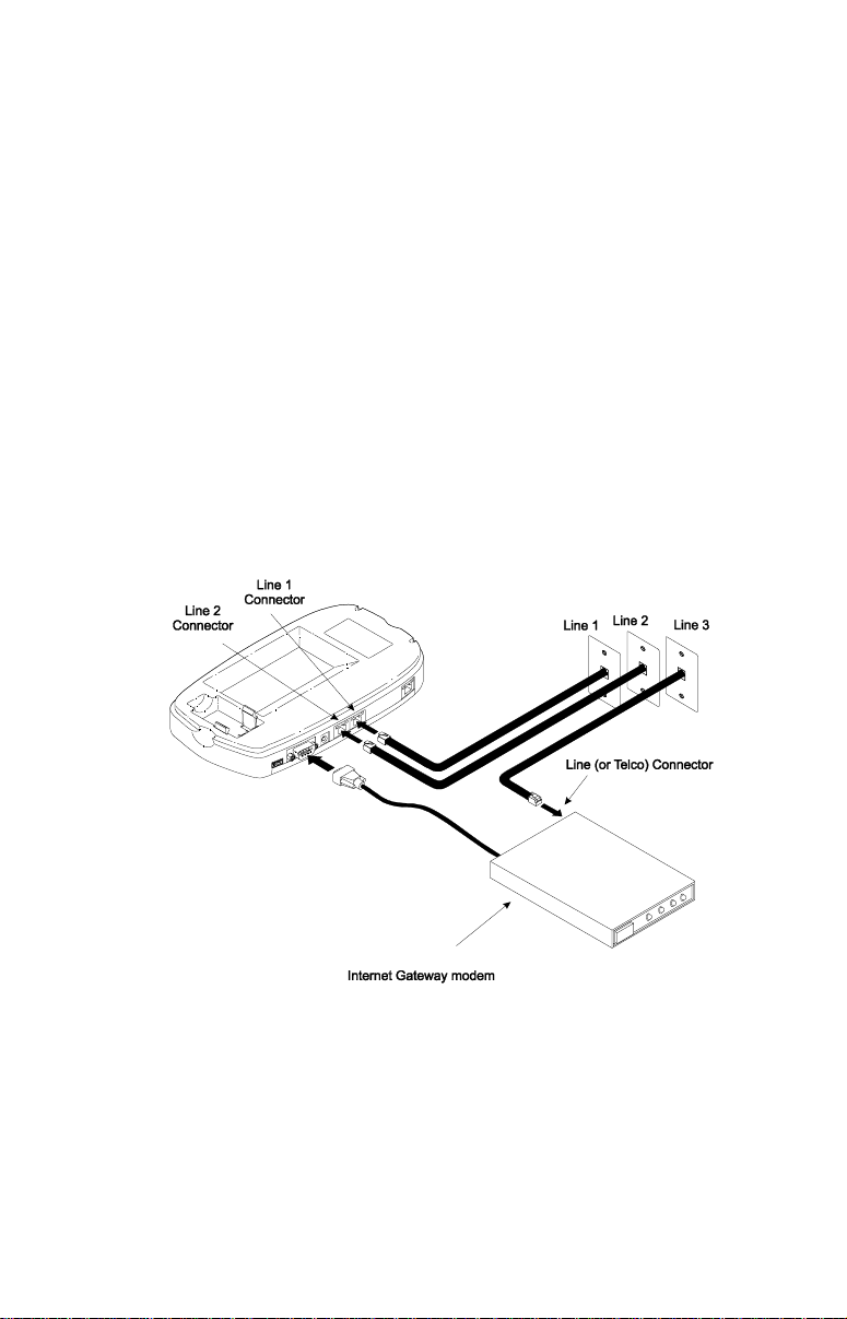
Connect a phone cable to the wall jack carrying your third
3
incoming phone line. Plug the other end of the cable into the
Line (or Telco) connector on the modem.
Connect one end of the modem serial cable to the modem as
4
described in the modem’s user manual. Connect the other end
of the cable to the serial port on the Controller.
Connecting the AirWay 308 Controller to single-line
wall jacks when installing an external modem using a
dedicated phone line
Installing the Controller • 25
Page 26
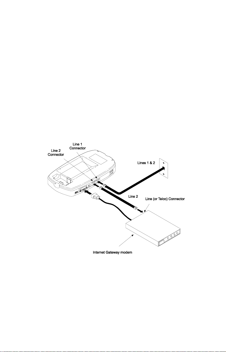
If external modem will share a phone line with the Controller
For two-line wall jacks
Connect a phone cable to the wall jack carrying your primary
1
incoming telephone lines (lines 1 and 2). Plug the other end of
the cable into the Line 1 connector on the Controller.
Plug one end of the pho ne li ne i nclu ded wi t h y our mod e m int o
2
the Line (or T elco) connect or on the modem. Plug the ot her end
into the Line 2 connector on the Controller. (The Controller
and modem will share Line 2.)
Connect one end of the modem serial cable to the modem as
3
described in the modem’s user manual. Connect the other end
of the cable to the serial port on the Controller.
Connecting the AirWay 308 Controller to 2-line wall
jacks when installing an external modem that will
share a phone line with the Controller
26 • Installing the Controller
Page 27
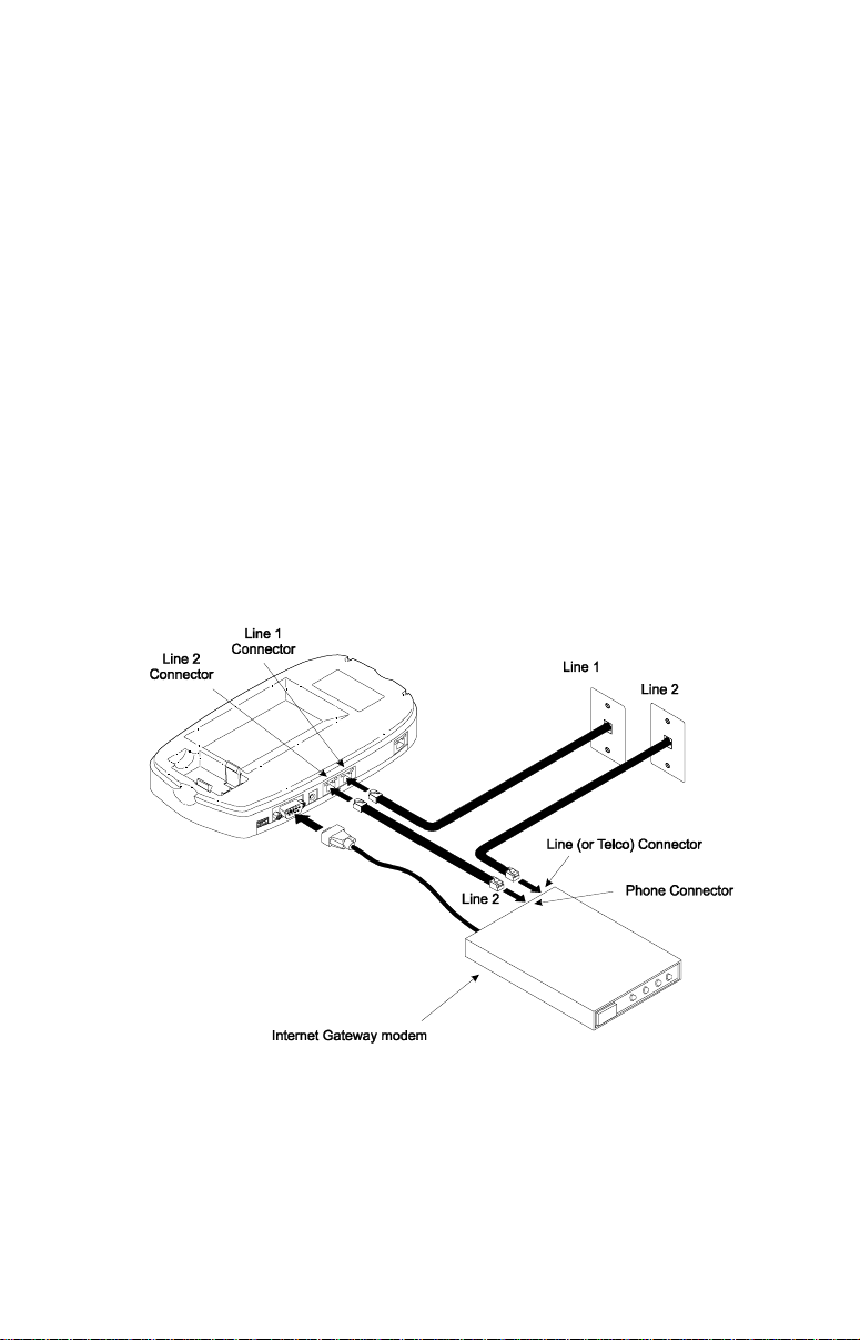
For single-line wall jacks
Connect a phone cable to the wall jack carrying your primary
1
incoming telephone line (Line 1). Plug the other end of the
cable into the Line 1 connector on the Controller.
Connect a phone cable to th e wall jack carry ing your secondary
2
incoming line (Line 2), then plug the other end of the cable in to
the Line (or Telco) connector on the modem.
Plug the phone cable in cluded with your modem into th e Phone
3
connector on the modem. Plug the other end into the Line 2
connector on the Controller. (The Controller and modem will
share Line 2).
Connect one end of the modem serial cable to the modem as
4
described in the modem’s user manual. Connect the other end
of the cable to the serial port on the Controller.
Connecting the AirWay 308 Controller to single-line
wall jacks when installing an external modem that will
share a phone line with the Controller
Installing the Controller • 27
Page 28
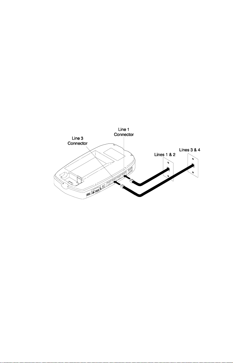
Connecting the AirWay 516 without External Modem
For 2-line wall jacks
Connect a phone cable to the wall jack carrying your primary
1
incoming telephone lines (lines 1 and 2). Plug the other end of
the cable into the Line 1 connector on the Controller.
If you have a second wall jack carrying additional incoming
2
lines, connect a phone cable from that wall jack to the Line 3
connector on the Controller . Be sure to le ave connectors 2 an d
4 empty.
Connecting the AirWay 516 Controller to 2-line wall
jacks if not installing an external modem
28 • Installing the Controller
Page 29
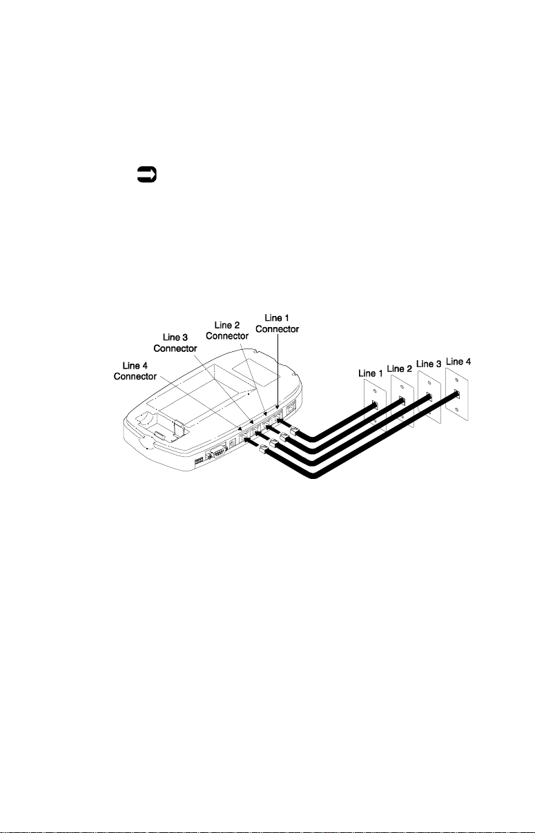
For single-line wall jacks
Connect a phone cable to the wall jack carrying your primary
1
incoming telephone line (line 1). Plug the other end of the
cable into the Line 1 connector on the Controller.
Connect lines 2, 3, and 4 to the Controller in the sa me manner.
2
Note:
The AirWay 516 Controller is packaged with two RJ14
telephone cables. If needed, you can obtain additional phone
cables from your local telephone supply st or e.
Connecting the AirWay 516 Controller to single-line
wall jacks if not installing an external modem
Installing the Controller • 29
Page 30

Connecting the AirWay 516 and External Modem
If external modem will use a dedicated phone line
For two-line wall jacks
Connect a phone cable to the wall jack carrying your primary
1
incoming telephone lines (lines 1 and 2). Plug the other end of
the cable into the Line 1 connector on the Controller.
Connect a phone cable to th e wall jack carry ing your secondary
2
incoming telephone lines (lines 3 and 4). Plug the other end of
the cable into the Line 3 connector on the Controller. Be sure
to leave the Line 2 and Line 4 connectors empty.
Connect a phone cable to a wall jack carrying another
3
incoming phone line. Plug the other end of the cable into the
Line (or Telco) connector on the modem.
Connect one end of the modem serial cable to the modem as
4
described in the modem’s user manual. Connect the other end
of the cable to the serial port on the Controller.
Connecting the AirWay 516 Controller to 2-line wall
jacks when installing an external modem using a
dedicated phone line
30 • Installing the Controller
Page 31
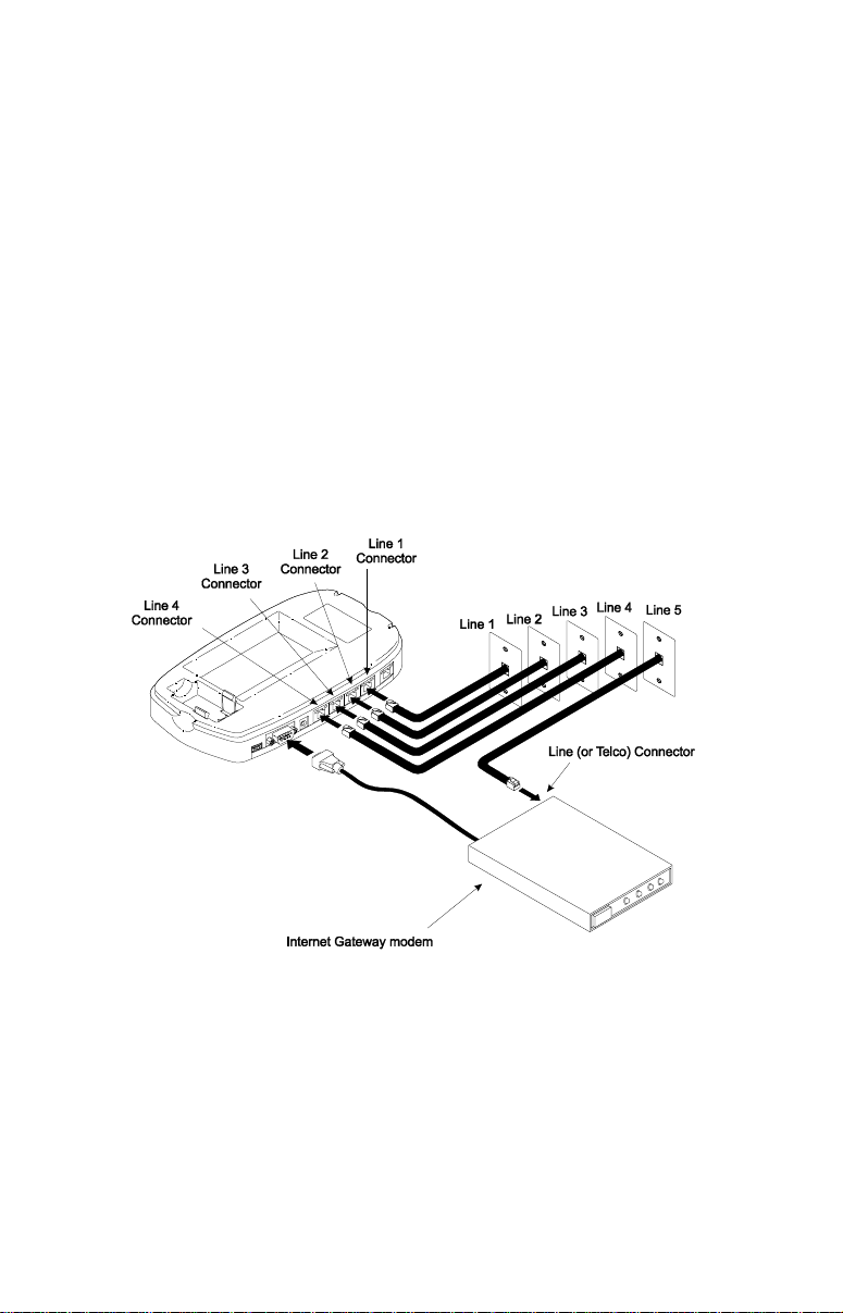
For single-line wall jacks
Connect a phone cable to the wall jack carrying your primary
1
incoming telephone line. Plug the other end of the cable into
the Line 1 connector on the Controller.
Connect lines 2, 3 and 4 in the same manner.
2
Connect a phone cable to a wall jack carrying line 5. Plug the
3
other end of the cable into the Line (or Telco) connector on the
modem.
Connect one end of the modem serial cable to the modem as
4
described in the modem’s user manual. Connect the other end
of the cable to the serial port on the Controller.
Connecting the AirWay 516 Controller to single-line
wall jacks when installing an external modem using a
dedicated phone line
Installing the Controller • 31
Page 32
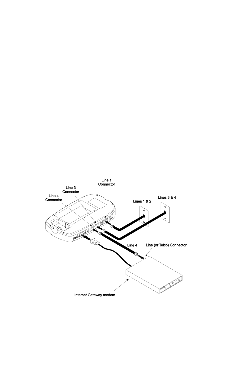
If external modem will share a phone line with the Controller
For two-line wall jacks
Connect a phone cable to the wall jack carrying your primary
1
incoming telephone lines (lines 1 and 2). Plug the other end of
the cable into the Line 1 connector on the Controller.
Connect a phone cable to th e wall jack carry ing your secondary
2
incoming telephone lines (lines 3 and 4). Plug the other end of
the cable into the Line 3 connector on the Controller. Be sure
to leave the line 2 connector empty.
Plug one end of the pho ne li ne i nclu ded wi t h y our mod e m int o
3
the Line (or T elco) connect or on the modem. Plug the ot her end
into the Line 4 connector on the Controller. (The Controller
and modem will share Line 4).
Connect one end of the modem serial cable to the modem as
4
described in the modem’s user manual. Connect the other end
of the cable to the serial port on the Controller.
Connecting the AirWay 516 Controller to 2-line wall
jacks when installing an external modem that will
share a phone line with the Controller
32 • Installing the Controller
Page 33
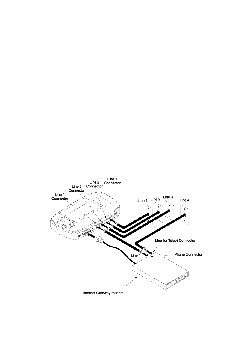
For single-line wall jacks
Connect a phone cable to the wall jack carrying your primary
1
incoming telephone line. Plug the other end of the cable into
the Line 1 connector on the Controller.
Connect lines 2 and 3 in the same manner.
2
Connect a phone cable to the wall jack carrying Line 4, then
3
plug the other end of the cable into the Line (or Telco)
connector on the modem.
Plug the phone cable in cluded with your modem into th e Phone
4
connector on the modem. Plug the other end into the Line 4
connector on the Controller. (The Controller and modem will
share Line 4)
Connect one end of the modem serial cable to the modem as
5
described in the modem’s user manual. Connect the other end
of the cable to the serial port on the Controller.
Connecting the AirWay 516 Controller to single-line
wall jacks when installing an external modem that will
share a phone line with the Controller
Installing the Controller • 33
Page 34
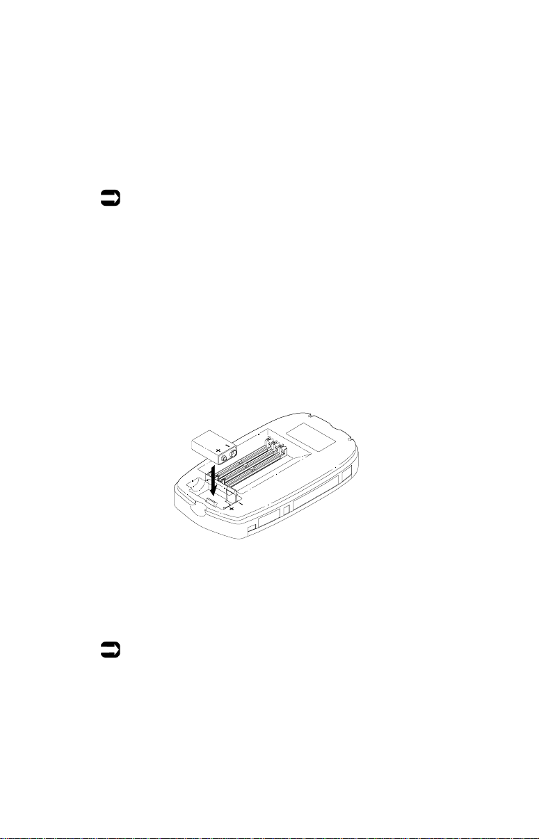
Installing the Battery
1
2
The Controller battery provides back-up power to your AirWay
network in the event of a power outage. When the battery needs to
be replaced, a low-battery warning displays on all HandSets in the
network. You should replace the Controller battery as soon as
possible when you see this warning.
Notes:
■ It is a good idea to change your Controller battery at least
once a year. Use only non-rechargeable 9V alkaline
batteries.
■ To preserve battery life, you should limit use of the
network during power outages to emergencies only.
With the Controller cover removed, insert the 9V battery in the
battery well. Be sure to observe proper polarity of the
connectors.
Replace the Controller cover.
Note:
Do not leave the Controller in operational status with the cover
removed. Always replace the cover after installing a battery.
34 • Installing the Controller
Page 35
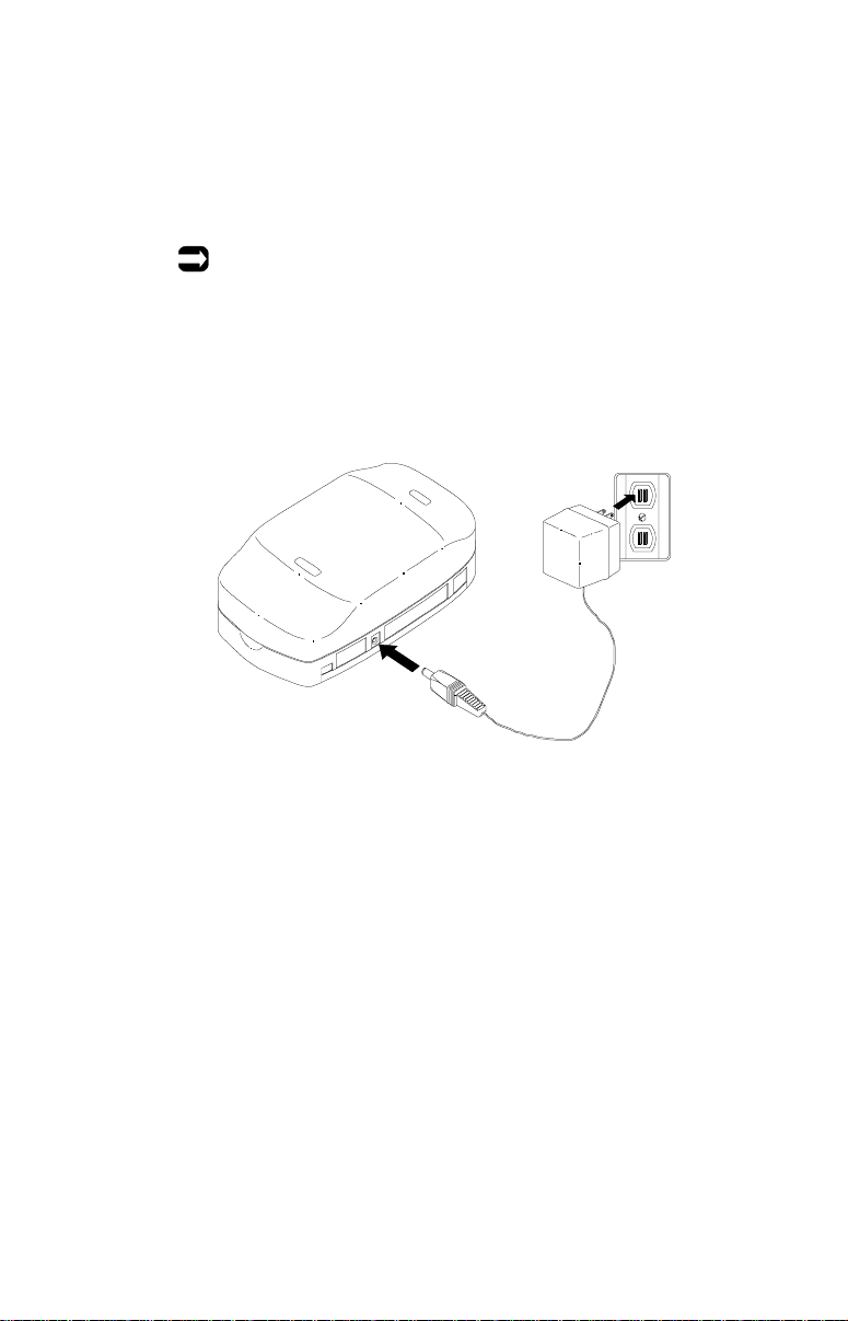
Connecting the Power
1
2
Connect the AC adapter power cord to the Controller.
Plug the AC adapter into a standard 120V electrical outlet.
Note:
Line connector LEDs on the Controller illuminate when the
Controller is receiving power.
Installing the Controller • 35
Page 36
Installing HandSets
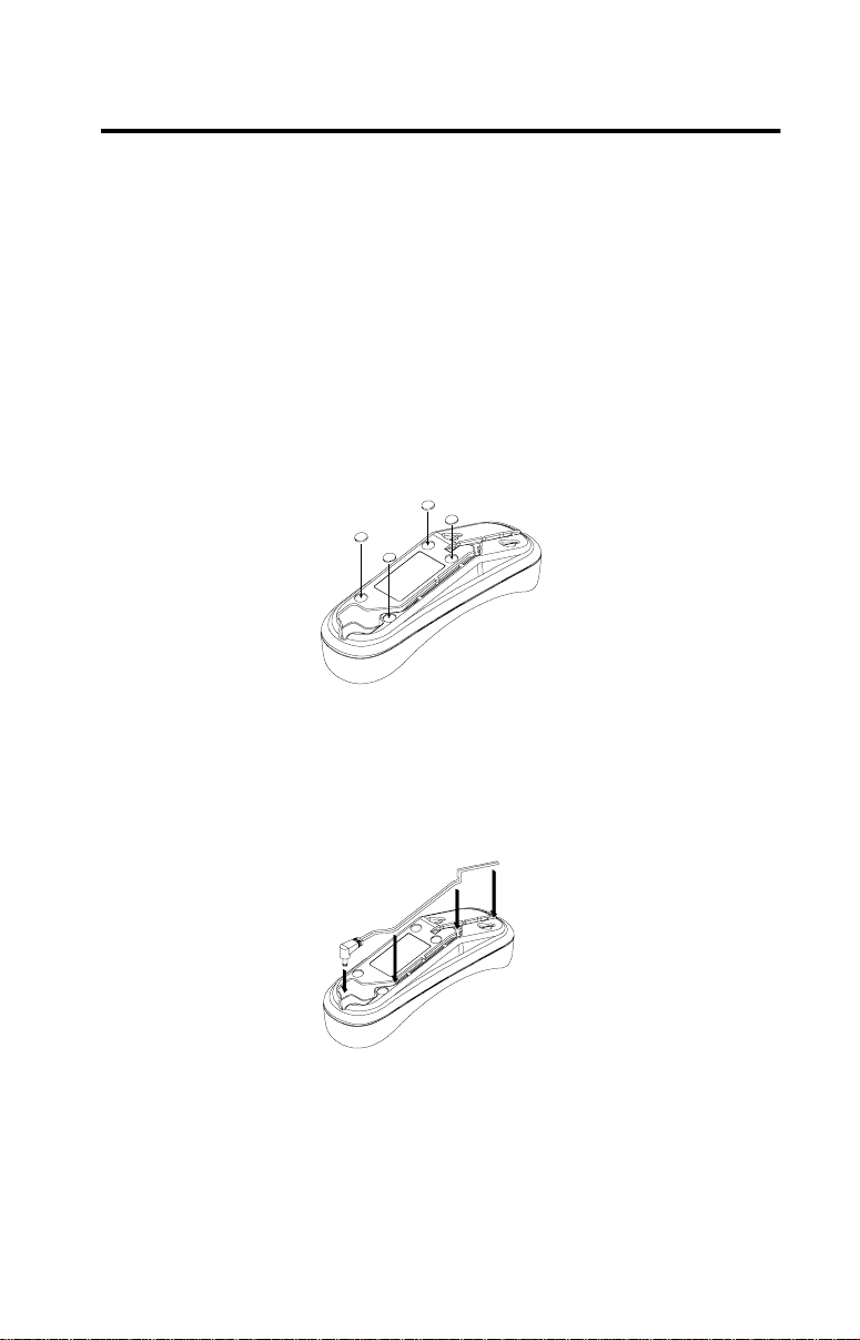
Preparing the Charging Cradle
Determine a location for the charging cradle.
1
■ If mounting the charging cradle on a wall, refer to the
wall-mounting instructions at the end o f this manual.
■ If placing the charging cradle on a horizontal surface,
attach the enclosed self-adhesive feet to the underside of
the cradle as shown in the following illustration.
Route the AC adapter cord through the channel in the charger
2
base.
Plug the AC adapter into a standard 120V electrical outlet.
3
36 • Installing HandSets
Page 37
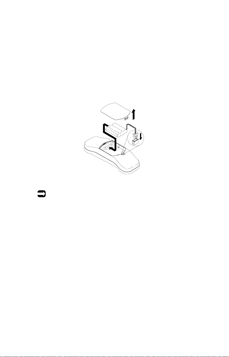
Installing and Charging the Battery Pack
T o achieve full battery capacity, charge new HandSet batteries for a
full 10 hours before initial use.
Remove the battery cover.
1
Connect the battery jack and insert the battery pack into place.
2
Note:
When replacing batteries, use only Nickel Cadmium (NiCad)
batteries supplied by Home Wireless Networks. To order
replacement batteries, call 1-888-WHY-WIRE (949-9473).
For information on recycling spent NiCad batteries, see page 16.
Installing HandSets • 37
Page 38
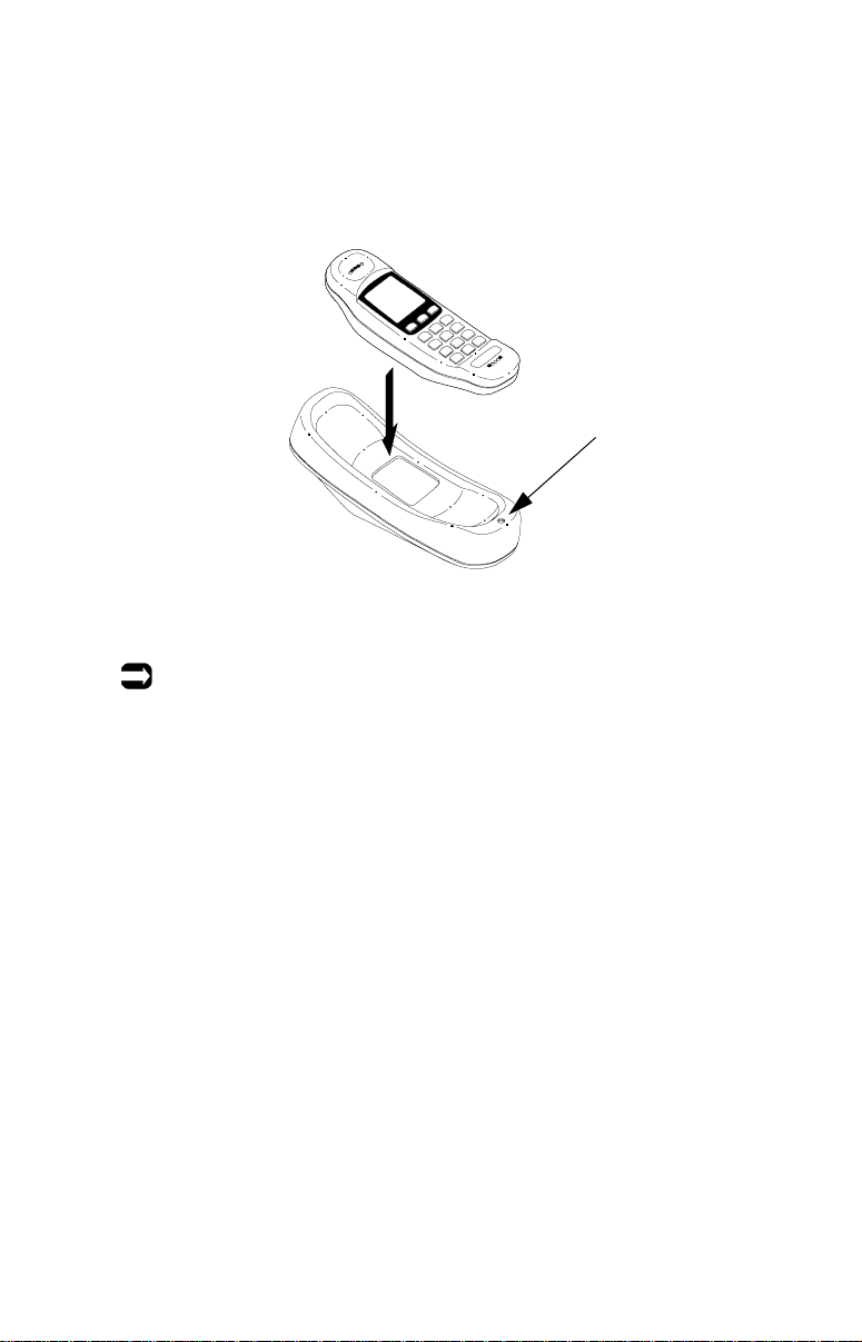
After replacing the battery cover, place the HandSet in the
3
charging cradle and charge it for at least 10 hours before use.
The HandSet will beep and the charger LED will illuminate
when the HandSet is properly seated in the charging cradle.
Charger LED
Notes:
■ If the charger is desk-mounted, the HandSet can be placed
either face up or face down in the cradle. If the charger is wallmounted, the HandSet must be face-up.
■ For best results and to prolong battery life, be sure to fully
drain the battery before recharging it. Batteries can be
recharged only while in the HandSet.
38 • Installing HandSets
Page 39

Registering a HandSet
About HandSet Re gistration
HandSets must be registered with the AirW ay Controller in order to
communicate with it. HandSets packaged with the Controller in an
AirWay Starter Kit are already registered with that Controller - all
you need to do before using the HandSet is install and charge the
battery.
You can register additional HandSets via either self-registration, or
from another HandSet already registered with the Controller. The
following steps describe the self-registration procedure. To register
additional HandSets from an already-registered HandSet, see page
75, "Adding HandSets and PhoneJacks to the network.”
Notes:
■ If you change Controllers for any reason, you must register
your HandSets with the new Controller.
■ If you carry your HandSet to a new location served by a
different Controller, you will need to re-register it with the new
Controller. Your HandSet will display an “Out of Range”
message when it loses communication with its registered
Controller. To register it with a different Controller, press
Hold/Menu, then 1. When the HandSet prompts you for the
Controller serial number, follow the procedure shown below.
Self-registration
When the HandSet asks for the Controller serial number, enter
1
the last eight digits of your Controller serial number. Press
END when finished.
Installing HandSets • 39
Page 40

When asked to confirm the serial number, press 1 (Yes) to
2
confirm or 2 (No) to re-enter the Controller serial number.
When asked for the Controller password, enter your current
3
Controller password, then press END. (See page 16 for information about the Controller password.)
When the HandSet locates the designated Controller, it
4
displays the idle screen. (Your screen may differ slightly from
the one shown below.) Your HandSet is now ready for use.
Note:
Y o u may want to set your system date & time at this point. See page
73, "Setting the time and date.”
40 • Installing HandSets
Page 41

If the HandSet cannot contact the Controller
If the HandSet is unable to contact the Controller, it displays
the screen shown below.
This can occur for several reasons.
■ The Controller is not plugged into a viable power source.
■ The Controller serial number and/or password were not
entered correctly. (Be sure to enter only the last eight
digits of the Controller serial n umber.)
■ You may be out of range of the Controller. The
Controller’ s max imum range is 1500 feet. This range can
be diminished by objects in the path of the signal. Move
closer to the Controller and try again.
Installing HandSets • 41
Page 42
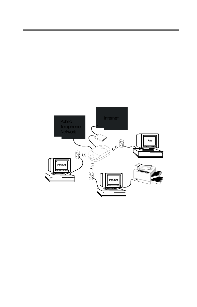
Installing DataJacks
Getting Started
DataJacks allow you to add desktop and laptop computers to your
AirW ay networ k. The networked computers can share n ot only files
and peripherals such as printers, scanners, etc. but they can also
access the same Internet account at the same time via an external
modem connected to your Controller.
System requirements
■ You must have one DataJack for each computer you wish to
add to the network.
■ You must have Windows 95, Windows 98, or Windows 98SE
installed on each computer.
■ The AirWay Controller must already be installed.
■ You must have an available 9-pin serial port on you r computer.
If your computer has a 25-pin serial port instead, you can use a
9-to-25 pin converter available from your local computer
supply store to adapt it to 9-pin.
42 • Installing DataJacks
Page 43

Items to have on hand
You may be asked for the following items during the software
installation process.
Windows CD-ROM
To prevent software conflicts, be sure to use the same version o f
Windows t hat is cu rren tly i nst al led o n your computer. If you do no t
have your Windows CD-ROM, the needed files may already be on
your computer in the Windows directory.
Example: C:\Windows\options\cabs.
AirWay System Information
Controller Serial Number _________________________
(Last eight digits only)
Controller Password _________________________
Note:
The Controller serial number is located on the label beneath the
Controller cover. For information about the Controller
password, see page 16.
ISP Information
If you have not already set up your AirWay network to connect to
the Internet but plan to do so, you will need to provide informat i on
about your Internet account during the software installation
process. This infor mation i s kno wn as an ISP profil e. (If you do not
have this information handy, you can obtain it from your Internet
Service Provider.)
Use the worksheet on the following page to record info about your ISP
Profile.
Installing DataJacks • 43
Page 44

ISP Profile Worksheet
Name of Internet Service Provider __________________________
(ISP Profile Name)
Internet Account User Name ____________________
Internet Account Password _____________________
Dial-in Phone Number _________________________
Is your IP address assigned automatically or manually? _________
If assigned manually, what is the:
IP Address: _____ . _____ . _____ . _____
Subnet Mask _____ . _____ . _____ . _____
Remote gateway address: _____ . _____ . _____ . _____
Domain Name Server #1: _____ . _____ . _____ . _____
Domain Name Server #2: _____ . _____ . _____ . _____
If your computer already has other LAN devices installed
In order for your DataJack to operate properly, it must be the only
active LAN device on your computer. If you have other LAN
devices such as Ethernet NIC, etc., installed on your computer, use
the following procedure to disable them before installin g the
AirWay DataJack.
1. On your Windows desktop, right click on My Computer.
2. Click on Properties, then select the Device Manager tab in the
System Properties window.
3. Under Network Adapter, select the device to be disabled and
click the Properties button. (You may need to double-click on
Network Adapters to see a drop-do wn list of availabl e networ k
devices.)
4. At the botto m of the General tab, click Disable in this
hardware profile, then click OK. A red X will appear over the
device to indicate that it has been disabled.
44 • Installing DataJacks
Page 45
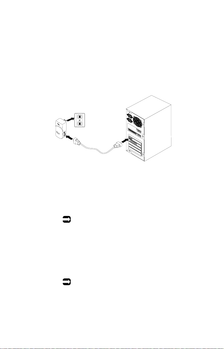
Connecting the DataJack
Connect one end of the DataJack cable to an available 9-pin
1
serial port on the computer. Connect the other end of the
cable to the DataJack.
Plug the DataJack into a standard 120V electrical outlet.
2
Installing the DataJack Software
Insert the AirWay DataJack CD-ROM in your CD drive.
1
Note:
If the AirWay s etup program doesn’t start automatically,
double-click My Computer, then double-click the icon for
your CD-ROM drive (usually either D: or E:).
Follow the instructions on the screen to install th e AirWay
2
DataJack in Control Panel and copy the needed files to your
computer. Restart your computer when prompted.
Note:
You may be prompted during the install process to insert
your Windows CD-ROM. Insert the CD-ROM and specify
the location of the Windows files. Examples: D:\Win95 ,
E:\Win95, D:\Win98, E:\Win98 .
Installing DataJacks • 45
Page 46

If you do not have your Wi ndows CD-ROM, the needed files
may already be installed on your computer. Specify the
directory where your Windows files reside and click OK.
Example: C:\Windows\options\cabs.
After restarting your computer, the AirWay Installation
3
Wizard checks to see if your DataJack has already been
registered with the Controller. If not, it displays the DataJack
Registration screen. Enter the last eight digits of your
Controller serial number and your 4-digit Controller
password, then click Next.
Notes:
■ DataJacks purchased as part of an AirWay Starter Kit
are already pre-registered with the Controller.
■ For information about your Controller password, see
page 16.
At the Computer Name screen, enter a name for your
4
computer to identify it on the network.
Note:
If your computer has previously been s et up as part of a
network, it will already have a comput er na me. Do not
change this name in the Computer Name screen.
If you have not already setup your AirWay network to
5
connect to the Internet or you wish to modify previously
specified ISP settings, select Yes at the Configuration Option
screen, then click Next.
If you do not want to set up or change your ISP information
at this time, click No and proceed to step 8.
If you selected Yes at the preceding step, the DataJack
6
Installation Wizard checks to see if any ISP settings already
exist on the Controller (through previous installatio n of a
DataJack on another network computer).
■ If it finds ISP settings on the Controller, the Installation
Wizard searches for a modem attached to the Contro ller .
If a modem is found, the Wizard gives you the
opportunity to change the modem settings. If a modem
is not found, the Wizard asks you to select a modem.
46 • Installing DataJacks
Page 47

After you have defined the mod e m, the Wizard displays
the Setup Summary screen. Proceed to step 8.
■ If the Installation Wizard cannot find ISP settings on
your Controller, it searches for the settings on your
computer. If it finds valid settings on your computer, it
displays the “Select Internet Settings” screen. Proceed
to step 7.
The “Select Internet Settings” screen shows all existing ISP
7
profiles found on your computer. Highlight the profile you
wish to use when connecting to the Internet via the AirWay
network, then click Next.
Note:
If you wish to define a new ISP profile, click Define New
Settings, then click Next. You will be asked to specify
settings for the new ISP profile, including the user name,
password, dial-up phone number , etc. Refer to the worksheet
on page 4 3 to complete t his section. Wh en you have finis hed
specifying the ISP information, click Next.
At the Setup Summary screen, click Back to modify any
8
settings, or Next to accept the settings as is and send them to
the Controller.
At the Installation Complete screen, select Yes, restart my
9
computer now, then click Finish. (You must restart your
computer in order for your changes to take effect.)
After restarting, your computer displays an AirWay icon in
the system tray (lower right-hand corner of the screen, next
to the time). This indicates a successful installation.
The AirWay icon is animated to show that the DataJack and
Controller are communicating with each other.
AirWay Icon
Installing DataJacks • 47
Page 48

Checking status of the comm link
T o check the status of the comm link between the the DataJack and
Controller, double-click the AirWay icon in your system tray.
The AirWay Monitor utility will open. If the Monitor utility shows
a green light, system status is normal and the DataJack and
Controller are in communication with each other. If the light is not
green, the DataJack has lost the comm link with the Controller.
Refer to page 97 for troubleshooting information.
48 • Installing DataJacks
Page 49
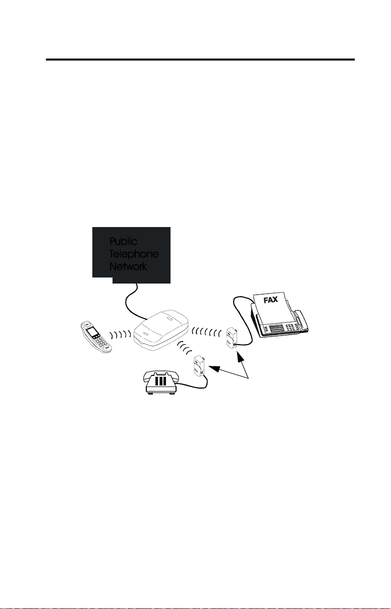
Installing PhoneJacks
Getting Started
AirWay PhoneJacks allow you to add wired (analog) telephone
devices such as fax machines, Caller ID boxes, or standard
telephones to your network. Once connected to the network, these
devices can access any available line in the network (unless
restricted via system setup).
Recording the serial number
Write down th e PhoneJack serial number before beginning the
installation process - you will need this information in order to
register the PhoneJack with the Controller. (The serial number is
located on the label on the jack.)
AirWay PhoneJacks
Installing PhoneJacks • 49
Page 50
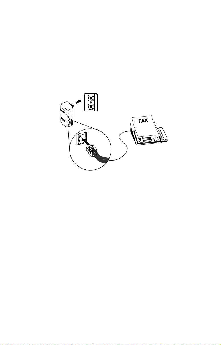
Connecting the PhoneJack
Plug the phone line from the standard telephone, fax machine,
1
etc., into the PhoneJack.
Plug the PhoneJack into a standard 120V electrical outlet. The
2
LED on the PhoneJack illuminates when it is receiving power
and in communication with the Controller.
Registering the PhoneJack
From a HandSet that is registered with the Controller, press
1
and release MENU until you reach the screen containing the
Setup function.
Press 9 (Setup).
2
Enter your Controller password, then press END.
3
Press 2 (Network).
4
Press 2 (PhoneJacks).
5
50 • Installing PhoneJacks
Page 51

Press 1 (Add).
6
Enter the last eight digits of the PhoneJack serial number.
7
Press END when finished.
Press 1 (Yes) to confirm the PhoneJack serial number and
8
name, or 2 (No) to re-enter the data.
Note:
New PhoneJacks are added with default names that match
their extension numbers. To change the default name, see
“Changing a device name” on page 77.
Press 0 when finished.
9
Configuring the Network For Use With PhoneJacks
Using a PhoneJack with a fax machine
If you are connecting a fax machine to your PhoneJack and have a
line that is used primarily for fax calls, use the following steps to
prevent other network devices such as HandSets from ringing
during incoming fax calls.
1. Set the fax machine to answer on the first ring.
2. Turn off inbound ringing for all network devices except the
PhoneJack your fax machine is connected to. For details, see
“Setting inbound ringing options” on page 79.
If desired, you can also p revent other net work devices from p lacing
outbound calls on the fax li ne by tur ning of f out bound li ne selecti on
for all devices except the PhoneJack your fax machine is connected
to. To turn off oubound line selection, see “Setting outbound line
selection options” on page 78.
Installing PhoneJacks • 51
Page 52

Using a PhoneJack with Caller ID/Call Waiting devices
If you subscribe to your p hone company’s Call Waiting with Caller
ID service (sometimes called Call Waiting Deluxe) and you have
connected a Caller ID box or display phone to an AirWay
PhoneJack, you will need to turn on Call Waiting Deluxe for the
PhoneJack so the Caller ID data will be displayed.
1. Press and release MENU until you reach the screen containing
the Setup function.
2. Press 9 (Setup), then enter your Controller password. Press
END when finished.
3. Press 2 (Network).
4. Press 2 (PhoneJacks).
5. Press 3 (Configure).
6. Enter the desired extension number, or scroll to it and press 0
(OK).
7. Press 4 to toggle Call Waiting Deluxe on or off. A checkmark
indicates that Call Waiting Deluxe is turned ON.
52 • Installing PhoneJacks
Page 53
Basic HandSet Operation
About Your HandSet Screens
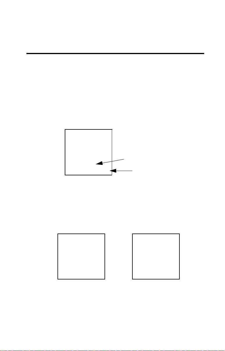
The Idle Screen
The Idle screen displays the system date and time, along with the
HandSet extension number and extension name.
HandSet name
Extension #
The Line Status Screen
To view the status of each line, press and release HOLD/MENU
until you reach the Line Status screen. See the following examples.
AirWay 308 AirWay 516
Basic HandSet Operation • 53
Page 54

The Menu Screens
The menu screens allow you to access your HandSet’s Caller ID,
Directory, Extensions, Call Privacy, Call Mute, HandSet Volume,
Ringer Volume, Conference, Transfer, and Setup options.
To reach the menu screens
Press and release HOLD/MENU until Main Menu Screen 1
appears. Press HOLD/MENU again to reach Main Menu Screen 2.
The following examples show Main Menu Screens 1 and 2. Some
of these screens also have sub-menus.
Main Menu Screen 1 Main Menu Screen 2
Scrolling through the menus
When in a menu screen, you can press END to return to the
previous screen. On some menu screens, y ou can also press * and #
to move back and forth in an entry.
54 • Basic HandSet Operation
Page 55

Using Your HandSet Features
Basic Calling Features
Answer an incoming call Press TALK.
Answer a specific line Press the line number of the ringing line.
Example: To answer a call on line 3, press
3.
Make a call using the first
available line
Make a call using a specific
line
End a call Press END.
Place a call on hold While on an active call, press HOLD. The
Retrieve a held call 1. Press and release HOLD until you
1. Press TALK.
2. When you hear dial tone, enter the
desired number.
1. Select the desired line number.
2. Dial the phone number.
Example: To make a call on Line 3, press
3, then dial the phone number.
line number of the Held call will flash.
reach the screen showing the held
call.
2. Press the line number of the held call.
Basic HandSet Operation • 55
Page 56

Answer a waiting call When you hear the Call Waiting tone, press
T ALK/FLASH to answer the waiting call.
Press TALK/FLASH again to return to
your original call. You can then toggle between the two calls using TALK/FLASH.
Notes:
■ You must subscribe to your telephon e
company’s Call Waiting service in
order to use this feature.
■ If you subscribe to Caller ID with
Call Waiting, the waiting party’s
Caller ID information appears on the
HandSet preceded by “W:”.
Call another extension 1. From the Idle screen or Main Menu
Screen 1, press 7.
2. Enter the desired extension number or
scroll down to it and pres s 0.
Notes:
■ The HandSet extension number is
displayed in the lower right hand
corner of the Idle and Line Status
screens on each HandSet.
■ To ring all extensions, scroll down to
the Ring All option and press 0.
Redial the last number
From a non-menu screen, press *.
called
Transfer a call 1. Press and release HOLD/MENU
until you reach the screen containing
the Transfer option.
2. Select Transfer from the list of menu
options.
3. Select the extension number you wan t
to transfer the call to.
4. Press 0 (Okay) to transfer the call.
56 • Basic HandSet Operation
Page 57
Mute a call The Mute function turns the HandSet
microphone off. You can still hear the
party on the other end, but they can’t hear
you.
When a call is muted, a mute symbol
displays on the HandSet next to the
muted call.
1. While on a call, press HOLD/MENU
and select Mute from the menu.
2. Select Mute again to unmute the call.
Make the current call
private
1. Press and release HOLD/MENU
until you reach the screen containing
the Call Privacy option.
When Call Privacy is turned on, a
lock symbol displays next to
the line number during active calls.
2. To turn Call Privacy off for the
current call, select Call Privacy again,
or hang up.
NOTES:
■ The above procedure affects only the
current call. To turn Call Privacy on
or off for all calls on a particular line,
see “Setting the Line Call Privacy
option” on page 82.
■ When Call Privacy is in effect, other
devices on the network cannot access
the line by pressing TALK.
Basic HandSet Operation • 57
Page 58
Caller ID Features
NOTE: In order to use the following Caller ID features, you must
subscribe to the Caller ID service provided by your telephone
company.
Incoming Caller ID calls
All HandSets in your AirWay network will display available Caller
ID data, unless inbound ringing for the line handling the call has
been turned off for a HandSet. Caller ID data is automatically saved
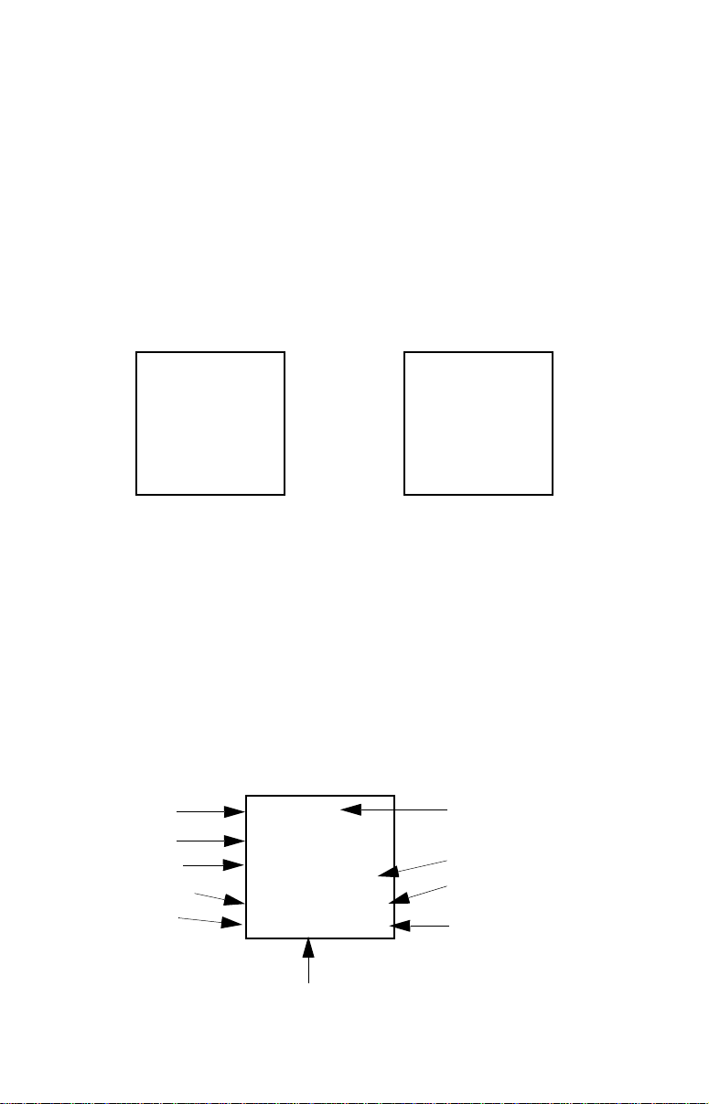
in a Caller ID log. The following example depicts a typical
incoming Caller ID call.
AirWay 308 AirWay 516
Caller ID Log
Y o u can reach the Ca ller ID Log by pressing 5 from the Idle Sc reen,
or by pressing HOLD/MEN U until you reach the screen containing
the Caller ID option, then pressing 5.
Calls are displayed in the Caller ID log in a first-in, first-out order.
You can dial from the Caller ID log, save a Caller ID record to your
Directory, or delete records from the Caller ID log. The following
example depicts a typical entry in a Caller ID log.
Line # call came
in on
Name of caller
Originating phone
number
Dial above number
Scroll to previous
Caller ID record
Delete this record from log
58 • Basic HandSet Operation
Time and date of call
# of calls from this party
Save Caller ID record
to Directory
Scroll to next Caller ID record
Page 59

Dial from the Caller ID log 1. Select the desired Caller ID record.
2. Press 5 and select the appropriate
dialing string from the “Dial As”
screen.
Save a Caller ID record to
the Directory
Delete a specific record
from the Caller ID Log
Delete all records from the
Caller ID Log
1. Select the desired Caller ID record.
2. Press 6 to save the Caller ID
information to the Directory.
3. For AirWay 516 systems, press 1 to
save to the System Directory or 2 to
save to the Personal Directory.
4. Select the appropriate dialing string
from the “Save As” list.
5. Press END.
1. Select the desired Caller ID record.
2. Press 9 to delete the record.
1. While in the Caller ID log, press and
hold 9 for at least 3 seconds.
2. When the confirmation screen
appears, press 1 (Yes) to clear all
records from the Caller ID log.
Basic HandSet Operation • 59
Page 60

Directory Features
The AirWay system allows you to store frequently called numbers
in custom dialing directories. The AirWay 308 and AirWay 516
both provide System Directories that are available to all HandSets
in the network. The System Directory on the AirWay 308 can store
up to 200 entries, while the System Directory on the AirWay 516
can store up to 50 entries.
The AirWay 516 also provides a Personal Directory for each
HandSet. Each Personal Directory can store up to 40 entries (up to a
maximum of 400 Personal Directory entries for the entire system).
Entries in a Personal Directory are available only to the HandSet
that stored them.
T o reach the Director y Main Menu, press 6 fro m the Idle Screen, or
press HOLD/MENU until you reach the screen containing the
Directory option, then press 6. (On the AirWay 516, you must then
press 1 at the Directory Main Menu to reach the System Directory,
or 2 to reach the Personal Directory.
Dial from the Directory 1. Locate the desired Directory entry.
2. Press 5 to dial the number.
Add an entry to the
Directory
60 • Basic HandSet Operation
Note: Directory names and numbers can
be up to 18 characters in length.
1. In the desired Directory, press 0 (Add
2. To enter the name, press and release
3. Enter the telephone number exactly as
4. Press 1 (Yes) if the directory entry is
entry).
the key for the desired letter until the
letter appears. Use * and # as
necessary to move back and forth
from one space to another . Press END
when finished.
it must be dialed, including “1” and/
or area code if appropriate. Press
END when finished.
correct, or 2 (No) to re-enter the data.
Page 61

Delete an entry from the
Directory
1. Locate the desired Directory entry.
2. Press 9 to delete the record from the
Directory.
Conference Calling Features
Initiate a Conference Call 1. Place all outside parties on hold.
2. Press and release HOLD/MENU
until you reach the screen containing
the Conference option.
3. Select Conference from the list of
menu options.
Join a Conference Call from
another extension
Drop out of or end a
Conference Call
Press a line number corresponding to one
of the outside lines in the conference.
Example: If Line 2 is being used for the
conference call, press 2.
Press END.
Note: The last internal extension to drop
out terminates the conference call.
Basic HandSet Operation • 61
Page 62

Miscellaneous General Features
Adjust the HandSet Volume 1. Press and release HOLD/MENU
until you reach the screen containing
the Volume option.
Note: If you were on an active call,
press the line number corresponding
to the call to return to it.
2. Select Volume from the list of menu
options to adjust the HandSet volume
up and down.
Adjust the Ringer Volume 1. Press and release HOLD/MENU
until you reach the screen containing
the Ringer volume.
2. Select Ringer from the list of menu
options to adjust the HandSet volume
up and down.
Use Call Forwarding You can forward all incoming calls on a
particular line to another number via the
Setup menu. For information on this procedure, see page 81, "Setting the Line Call
Forwarding option.”
Use Voice Mail If you subscribe to a Voice Mail service,
all HandSets in the network display a
“Message Waiting Line x” message on the
Idle screen when a message waiting signal
is sent by the telephone company.
Note: For information on activating the
Voice Mail feature on your network, see
page 85, "Turning Voice Mail On and
Off.”
62 • Basic HandSet Operation
Page 63

Locate a misplaced HandSet Option 1
If you know the extension number of the
missing HandSet, you can dial it from
another HandSet. This option causes only
the called HandSet to ring.
Example: To locate extension 12, select
Extension 12 on the Extensions menu, or
simply press “12.”
Option 2
If you don’t know the extension number of
the missing HandSet, you can use another
HandSet to ring all HandSets in the
network.
1. From the Idle Screen, press 7
(Extensions).
2. Scroll through the displayed items
until “Ring all” is highlighted.
3. Press 0 (Ring all).
Basic HandSet Operation • 63
Page 64

Sharing Data Network Resources
The following pages provide basic information on sharing files,
printers and Internet access with other computers in your AirWay
network. These procedures may differ slightly from one version of
Windows to another. If you need additional help setting up shared
files or printers, click the Start button on your Windows taskbar,
then click Help to access your Windows online help files.
Sharing Files
Setting up shared folders on your computer
Before you can transfer files between network computers, yo u must
designate which folders will be shared on each computer.
Note:
Shared folders are indicated by a symbol in My
Computer.
On the computer containing the folder you want to share, point
1
to My Computer on the Windows desktop and click your right
mouse button.
Click Explore, point to the folder you want to share, then click
2
your right mouse button.
Click Sharing.
3
Note:
If you want to create a new folder to share, navigate to where
you want the shared folder to be, then click File. Poin t to New,
then click Folder. Name the new folder and press Enter. With
the new folder still highlighted, click your right mouse butto n,
then click Sharing.
64 • Sharing Data Network Resources
Page 65

Click Shared As, then specify the access type for the folder.
4
You will also need to specify ap propriate passwords for the
access type.
■ Read-Only means that other computers can view files in
the folder, but cannot change or delete them.
■ Full means that other computers can view, copy, change,
save, and delete files in the folder.
■ Depends on Password allows you to control the type of
access different computers have by setting separate
passwords for Read-only and Full acces s.
Copying files to another computer
On your Windows desk t op, dou bl e-cl ic k Networ k
1
Neighborhood.
In the Network Neighborhood window, double-click on the
2
destination computer to view the shared folders on that
computer.
On the sending computer, navigate to the folder containing the
3
file you want to transfer.
Point to the file you want to transfer, then press and hold down
4
your left mouse button while you drag the file icon to the
shared folder on the destination computer.
Sharing Data Network Resources • 65
Page 66

Sharing Printers
Remember the following points when setting your network up for
printer sharing:
■ The printer must be connected to a computer that is part of the
AirWay network.
■ Both the printer and the computer it is connected to must be
turned on, and the printer must be set up as “shared” on the
computer.
■ File and print sharing must be enabled on both computers.
■ The printer drivers must be install ed on all computers you want
to print from (not just the computer physically connected to the
printer).
Note:
Some computers have a power-saving featu re that puts them in
“sleep” mode when not in use. If the printer you want to print
to is connected to such a computer, make sure it is not in sleep
mode when you send a document to the printer.
To set up a shared printer
On the computer that is connected to the printer, click Start,
1
point to Settings, then click Printers.
In the Printers window, point to the printer you wish to share
2
and click your right mouse button.
Click Sharing, then click Shared As.
3
Click OK.
4
To install a shared printer on another com pu ter
On the computer where you want to install the printer, double-
1
click Network Neighborhood.
Double-click on the computer that is connected to the printer.
2
66 • Sharing Data Network Resources
Page 67

Click on the printer you want to share, then click File In stall .
3
Follow the instructions in the Add Printer Wizard to finish
4
installing the printer.
Note:
You may be asked for the floppy disk or CD-ROM containing
the drivers for the printer.
Printing to a shared printer from another comput er
In a Windows application, click File, then Print.
1
In the Print window, click the down arrow to the right of
2
Printer Name.
Click on the printer you want to use.
3
Sharing an Internet Connection
If you have connected an external modem to your AirWay
Controller, your network computers can share a single Internet
connection. This means that you only need to have one Internet
account - everyone in the network can log on at the same time and
surf the web, check e-mail, etc.
Note:
You cannot use these procedures to log onto an America
Online (AOL) account. If you are using AOL, you must
manually log onto AOL using the normal AOL dial-up
procedure. Also, America Online (AOL) does not allow
multiple computers to log on at the same time to the same
account.
Configuring your computer to connect via the AirWay LAN
Normally, a computer connects to the Internet using its own local
modem. To connect using the Controller’s external modem in stead,
you need to change your computer’ s Inter net connection pr operties .
This procedure varies somewhat from one browser version to
another.
Sharing Data Network Resources • 67
Page 68

For Netscape Navigator
If you are using Netscape Navigator, you must change your Internet
connection settings in both Windows Control Panel and in
Navigator. See the following tables for information on changing
these settings.
Changing the Internet connection settings in Control Panel
1. Cli c k Start>Settings>Control Panel.
2. Doub le-click the Internet icon.
3. Select the Connection folder.
4. Select “Never dial a connection.”
5. Click OK.
Changing the Internet connection settings in Navigator 3.0
1. Start Netscape Navigator.
2. Select File>Options/Network Preferences.
3. Select the Prox ies folder.
4. Select “Automatic Proxy Configuration.”
5. Click OK.
Changing the Internet connection settings in Navigator 4.0
1. Start Netscape Navigator.
2. Select Edit>Preferences.
3. In the Category window, click the + symbol next to
“Advanced.”
4. Select Proxies from the drop down list.
5. In the Proxy window on the right, select Automatic Proxy
Configuration. (You do not need to enter a con figurat ion UR L.)
6. Click OK.
68 • Sharing Data Network Resources
Page 69

For Internet Explorer
If you are using Internet Explorer, you only need change the
Internet connection settings in the browser. The changes are
automatically reflected in Control Panel.
Internet Explorer 3.0
1. Start Internet Explorer.
2. Select View>Options.
3. Select the Connection folder.
4. Make sure “Connect to the Internet as needed” is NOT
checked.
Internet Explorer 4.0
1. Start Internet Explorer
2. Select View>Internet>Options.
3. Select the Connection folder.
4. Under Connection, select “Connect to the Internet using a local
area network.”
5. Click OK.
Sharing Data Network Resources • 69
Page 70

Accessing the Internet
You can set your computer up to autoconnect to the Internet
whenever you open your web browser, or you can initiate a
connection without opening your web browser.
Auto-connecting to the Internet by opening your web browser
Use the following procedure to set your computer up so that it
connects automatically to the Internet whenever you open your web
browser:
Right-click the AirWay icon in your system tray.
1
Select Turn Autoconnect On from the pop-up menu.
2
AirWay Icon
Open your web browser. If the AirWay network is not already
3
connected to the Internet, it automatically dials your ISP.
To turn the auto-connect feature off, right-click the AirWay
4
icon again and select Turn Autoconnect Off from the pop-up
menu.
Note:
Exiting out of your web browser does not automatically
terminate the Internet connection (the connection stays active
until the time specified under Dialing Properties in AirWay
Network Settings). If you wish to end the Internet connection
immediately , right-click on the AirWay icon and select
Disconnect from the po p-u p men u. Be aware however that this
option will also disconnect other users in the AirWay network.
70 • Sharing Data Network Resources
Page 71

Connecting to the Internet using the AirWay Connect option
Use the following procedure to initiate a connection to the Internet
without opening your web browser.
Right-click the AirWay icon in your system tray.
1
Select Connect from the pop-up menu. If the AirWay network
2
is not already connected to the Internet, it automatically dials
your ISP.
T o disconnect from the Internet, right-click the AirWay icon in
3
your system tray and select Disconnect from the pop-up menu.
Note:
The Disconnect option immediately terminates the Internet
connection. It is therefore a good idea to make sure that no one
else in the network is using the Internet before disconnecting or
they will be disconnected also.
Sharing Data Network Resources • 71
Page 72
Modifying Your Voice Network Settings
You can perform system administration of your AirWay network
using the Setup menu of a registered Hand Set. (You will be
required to enter your Controller passwo rd to enter the Setup
menu.)
To do this... See page
Set system time/date 73
View software version 73
Change Controller password 74
Add new HandSets or PhoneJacks 75
Remove HandSets, PhoneJacks, and DataJacks 76
Change device names 77
Set outbound line selection options 78
Set inbound ringing options 79
Turn Call Waiting Deluxe on or off for PhoneJacks 80
Set call forwarding options 81
Set line call privacy options 82
Set line ringing pattern 82
Set system timer for Hold Recall 83
Set system timer for Transfer Recall 84
Set system timer for Call Forward Disconnect 84
Turn Voice Mail on or off 85
72 • Modifying Your Voice Network Settings
Page 73

General System Information
Setting the time and date
Use the following procedure to set your system
date, time, and day of week.
1. Press and release HOLD/MENU until you
reach the screen containing the Setup
function.
2. Press 9 (Setup) and enter your Controller
password. Press END when finished.
3. Press 1 (General), then 1 (Time/Date).
4. Enter the correct time and date as follows:
■ Press 1 to increment the hour
■ Press 2 to increment the minute
■ Press 3 to increment the day
■ Press 4 to increment the month
■ Press 5 to increment the date.
■ Press END when finished.
Note:
If you subscribe to your local telephone
company’s Caller ID service, the system
time and date is verified against incoming
Caller ID data and reset if necessary.
Verifying the system software version
You can verify your system’s software version
using the following procedure.
1. Press and release HOLD/MENU until you
reach the screen containing the Setup
function.
2. Press 9 (Setup) and enter your Controller
password. Press END when finished.
3. Press 1 (General), then 2 (System Info).
Modifying Your Voice Network Settings • 73
Page 74

Changing the Controller password
You may find it necessary to change your
Controller password from time to time. The
password is used to prevent unauthorized
individuals from registering devices on your
system.
The Controller comes with a default password of
1234. You should change this p a ss word to one of
your own choosing as soon as you have finished
installing and setting up your network.
Passwords must be a 4-digit number. Write your
password down and keep it in a safe place. You
will need the password to perform all system
administration task s.
1. Press and release HOLD/MENU until you
reach the screen containing the Setup
function.
2. Press 9 (Setup), then enter your Controller
password. Press END when finished.
3. Press 1 (General), then 3 (Password).
4. Enter the current password, then press END.
5. E nte r the new passwor d, then press END.
6. Press 1 to confirm the new password, 2 to re-
enter the new password, or 3 to cancel.
Notes:
■ You can reset your Controller to the system
default of 1234 by disconnecting the
Controller power cord and removing the
battery, waiting 10 seconds, then reinserting
the battery and reconnecting the power cord.
■ In case of a power failure accompanied by a
low Controller battery condition, the
password automatically resets to 1234.
74 • Modifying Your Voice Network Settings
Page 75

Managing Network Devices
Adding HandSets and PhoneJacks to the network
You can add additional HandSets or PhoneJacks
to your AirWay network from a registered
HandSet using the following procedure.
1. Press and release HOLD/MENU until you
reach the screen containing the Setup
function.
2. Press 9 (Setup), then enter your Controller
password. Press END when finished.
3. Press 2 (Network).
4. Press 1 if adding a HandSet or 2 if adding a
PhoneJack.
5. Press 1 (Add), then enter the last eight digits
of the new device’s serial number.
6. Press END to accept the default name or use
the keypad to overwrite the default name
with a new name.
7. Press 1 to verify the serial number and n ame,
2 to re-enter the data, or END to cancel.
8. When the display reads “HandSet Added”
(or “PhoneJack Added”), press 0.
Notes:
■ HandSet serial numbers are located on the
underside of the battery cover. PhoneJack
serial numbers are located on the plug side of
the PhoneJack.
■ New network devices are added with a
default name of “ExtXX,” where “XX” is the
next available extension number. HandSets
are numbered sequentially beginning with
Ext 10, while PhoneJacks and DataJacks are
numbered seque ntially beginning with Ext
51 (DataJacks can be added only from a
network computer).
Modifying Your Voice Network Settings • 75
Page 76

■ To enter a new name for the device, press
and release the key for the desired letter until
the letter appears. Use * and # as necessary
to move back and forth from one space to
another. Press END when finished entering
the new name.
Removing Devices from the network
You can remove a HandSet, PhoneJack, or
DataJack from the network using the following
procedure. Removing a device disables the
Controller’s ability to communicate with that
device. It is generally a good security measure to
remove lost devices from the network.
1. Press and release HOLD/MENU until you
reach the screen containing the Setup
function.
2. Press 9 (Setup), then enter your Controller
password. Press END when finished.
3. Press 2 (Network).
4. Press 1 if removing a HandSet, 2 if removi ng
a PhoneJack, or 5 if removing a DataJack.
5. For HandSets or PhoneJacks, press 2
(Remove).
6. Enter the extension number of the device to
be removed, or scroll through the entries to
select it and press 0 (OK).
7. Press 1 to verify removal of the device, 2 to
end the procedure without removing the
device, or END to cancel.
8. When the display reads “HandSet Removed”
(or PhoneJack or DataJack Removed), press
0.
76 • Modifying Your Voice Network Settings
Page 77

Changing a device name
You can change the name of a network device
using the following procedure.
1. Press and release HOLD/MENU until you
2. Press 9 (Setup), then enter your Controller
3. Press 2 (Network).
4. Press 1 for a HandSet or 2 for a PhoneJack.
5. Press 3 (Configure).
6. Enter the extension number of the device to
7. Press 1 (Edit Name), then enter the new
reach the screen containing the Setup
function.
password. Press END when finished.
be renamed. (You can also use * and # to
scroll through the entries. When the desired
device is highlighted, press 0 (OK).)
name using the keypad. Press and release the
key for the desired letter until the letter
appears.
Note:
Continue pressing the key for each letter to
scroll through the letters in CAPS and lower
case. Use * and # as necessary to move back
and forth from one space to another.
Example:
T o enter the name “Tom” -
■ Press 8 one time to add “T”;
■ Press 6 three times to add “o”;
■ Press # to advance to the next space;
■ Press 6 one time to add “m”;
■ Press # to advance to the next space;
■ Press 0 as many times as necessary to
delete any remaining unwanted text.
8. Press END when finished editing the device
name.
Modifying Your Voice Network Settings • 77
Page 78

Setting outbound line selection options
AirWay 516
AirWay 308
Outbound Line Selection options determine
which lines an extension can access for outgoing
calls by pressing the Talk key. The extension is
only prevented from reaching the restricted line
when pressing T alk - it can still access the line by
pressing the line number.
Example: You have connected a fax machine to
your AirWay network using a PhoneJack. You
want to keep Line 2 free for the fax machine, so
you restrict all HandSets from dialing out on Line
2 via the Talk key.
1. Press and release HOLD/MENU until you
reach the screen containing the Setup
function.
2. Press 9 (Setup), then enter your Controller
password. Press END when finished.
3. Press 2 (Network).
4. Press 1 if the extension being configur ed is a
HandSet, or 2 if the extension being
configured is a PhoneJack.
5. Press 3 (Configure), then enter the extension
number you want to set outbound line
selection for.
Note:
Y ou can al so use * and # to scr oll through the
entries. When the desired device is highlighted, press 0 (OK).
6. Pr ess 2 (Outbound line selection).
78 • Modifying Your Voice Network Settings
7. Toggle the d esired li nes on or o ff by pressing
the corresponding line number. A check
mark indicates that outbound l ine selectio n is
turned ON for that extension.
8. Press END when finished.
Page 79

Setting inbound ringing options
AirWay 308
AirWay 516
Inbound Ringing options allow you to specify
which extensions ring with inbo un d calls on a
particular line. When you turn off inbound
ringing on a line for an extension, that extension
does not ring when calls come in on the line.
When inbound ringing from other extensions is
turned off, the extension will not ring with calls
from other extensions in the network.
Note:
Turning off inbound ringing for an extension
also prevents the extension from using the
Talk key to answer calls on the restricted
line. The extension is only prevented from
answering the restricted line when pressing
Talk - it can still access the ringing line by
pressing the line number.
Example: One of your phone lines (Line 2) is an
800 number . You want incoming calls on that lin e
to ring only on certai n exte nsions , so you t urn off
inbound ringing on Line 2 for other extensions.
1. Press and release HOLD/MENU until you
reach the screen containing the Setup
function.
2. Press 9 (Setup), then enter your Controller
password. Press END when finished.
3. Press 2 (Network).
4. Press 1 if the extension being configur ed is a
HandSet, or 2 if the extension being
configured is for a PhoneJack.
5. Press 3 (Configure), then enter the extension
number you want to set inbound ringing for.
Note:
Y ou can al so use * and # to scr oll through the
entries. When the desired device is highlighted, press 0 (OK).
Modifying Your Voice Network Settings • 79
Page 80

6. Press 3 (Inbound ringing).
7. Toggle the d esired li nes on or o ff by pressing
the corresponding line number. A check
mark indicates that inbound ringing is turned
ON for that extension.
8. Press END when finished.
Turning Call Waiting Deluxe on/off for PhoneJacks
If you subscribe to your phone company’s Call
W aiting with Caller ID service (sometimes called
Call Waiting Deluxe) and you have a Caller ID
box or display phone connected to your AirWay
system via a PhoneJack, you will need to turn on
Call Waiting Deluxe for that PhoneJack so the
Caller ID data will be displayed.
1. Press and release HOLD/MENU until you
reach the screen containing the Setup
function.
2. Press 9 (Setup), then enter your Controller
password. Press END when finished.
3. Press 2 (Network).
4. Press 2 (PhoneJacks).
5. Press 3 (Configure).
6. Enter the desired extension number, or scroll
to it and press 0 (OK).
7. Press 4 to toggle Call Waiting Deluxe on or
off. A checkmark indicates that Call Waiting
Deluxe is turned ON.
80 • Modifying Your Voice Network Settings
Page 81

Setting Phone Line Options
Setting the Line Cal l Forwarding option
Your AirWay network allows you to forward
incoming calls on a specific line to another
external phone number. If desired, a different
external Call Forwarding number can be set fo r
each line in the network.
Note:
This procedure will tie up two lines while a
forwarded call is in progress. To avoid tying
up your system for lon g p eri ods of t im e, yo u
may want to set the Call Forward Disconnect
timer. See page 84 for information on setting
the Call Forward Disconnect timer.
1. Press and release HOLD/MENU until you
reach the screen containing the Setup
function.
2. Press 9 (Setup), then enter your Controller
password. Press END when finished.
3. Press 2 (Network), then 3 (Lines).
4. Select the desired line number.
5. Press 1 to toggle Call Forwarding on or off.
6. If you turned Call Forwarding “ON” in the
preceding step, enter the phone number the
calls should be forwarded to. (Enter the
number exactly as it should be dialed,
including 1 and/or area code if needed.)
Press END when finished.
7. Press 1 (Yes) to confirm the Call Forwarding
number, or 2 (No) to re-enter the number.
Modifying Your Voice Network Settings • 81
Page 82

Setting the Line Cal l Privacy option
Y ou can turn Call Privacy on or off for all calls on
a particular line. When Call Privacy is set, other
devices on the network (except one plugged into
a wall jack carrying that line) cannot listen in or
break in on an active call on the line.
Note:
T o override this setting for a current call, see
page 57, "Make the current call private.”
1. Press and release HOLD/MENU until you
reach the screen containing the Setup
function.
2. Press 9 (Setup), then enter your Controller
password. Press END when finished.
3. Press 2 (Network), then 3 (Lines).
4. Select the desired line number.
5. Press 2 to toggle Line Privacy on or off. A
checkmark indicates that Call Privacy is
turned O N for that line.
6. Pr e ss END when finished.
Setting Ring Patterns
You can specify a different ring pattern for all
incoming calls on a specific line. This is
convenient if you have a particular line d edicated
for business calls, for instance, and you want to
be able to distinguish incoming calls on that line
from other incoming calls.
1. Press and release HOLD/MENU until you
reach the screen containing the Setup
function.
2. Press 9 (Setup), then enter your Controller
password. Press END when finished.
3. Press 2 (Network), then 3 (Lines).
4. Select the desired line number.
82 • Modifying Your Voice Network Settings
Page 83

5. Select 3 (Ring pattern).
6. Select one of the five ringing pattern options.
7. Press END when finished.
Note:
If you subscribe to your telephone com-
pany’s Distinctive Ringing service and want
to use that pattern instead of one of the network patterns, be sure to select Normal.
Setting System Timers
Setting the Hold Recall Timer
The Hold Recall Timer determines how long a
call will remain on hold before a reminder tone
sounds on the extension that placed it on hold.
When a held call recalls back to the extension,
the user hears a ring tone and the HandSet
displays “Recall Line X.”
1. Press and release HOLD/MENU until you
reach the screen containing the Setup
function.
2. Press 9 (Setup), then enter your Controller
password. Press END when finished.
3. Press 2 (Network), then 5 (Timers).
4. Press 1 (Hold recall) and select the desired
timer option.
5. Press END when finished.
Modifying Your Voice Network Settings • 83
Page 84

Setting the Transfer Recall Timer
The Transfer Recall T ime r determines how long a
transferred call will go unanswered before it r ings
back to the transferring extension. When a
transferred call recalls to the transferring
extension, the user hears a ring tone and the
HandSet displays “Recall Line X.”
1. Press and release HOLD/MENU until you
reach the screen containing the Setup
function.
2. Press 9 (Setup), then enter your Controller
password. Press END when finished.
3. Press 2 (Network), then 5 (Timers).
4. Press 2 (Transfer recall) and select the
desired timer op tion.
5. Pr ess END when finished.
Setting the Call Forward Disconnect Timer
The Call Forward Disconnect Timer determines
how long the system will allow a forwarded call
to remain in progress. This prevents forwarded
calls from tying up two lines on your system for
longer than desired.
1. Press and release HOLD/MENU until you
reach the screen containing the Setup
function.
2. Press 9 (Setup), then enter your Controller
password. Press END when finished.
3. Press 2 (Network), then 5 (Timers).
4. Press 3 (Call Forward Disconnect) and select
one of the five timer options.
5. Press END when finished.
84 • Modifying Your Voice Network Settings
Page 85

Using Voice Mail
AirWay 308
AirWay 516
Turning Voice Mail On and Off
If you subscribe to your telephone company’s
voice mail service, you can configure your
network to display a “Message Waiting”
indicator on each HandSet in the network.
1. Press and release HOLD/MENU until you
reach the screen containing the Setup
function.
2. Press 9 (Setup), then enter your Controller
password. Press END when finished.
3. Press 3 (Voice Mail).
4. Press the desired line number to toggle
message waiting detection on and off. A
checkmark indicates that message waiting
detection is turned on.
5. Press END when finished.
Modifying Your Voice Network Settings • 85
Page 86

Modifying Your Data Network Settings
The AirWay DataJack software allows you to make the following
changes to your network settings:
■ Register your DataJack with another Controller
■ Change your computer’s network name
■ Change ISP profiles, modems, and dialing properties to use
when connecting to the Internet via an external modem
connected to the Controller.
Changing Controllers
There may be times when you wish to register your DataJack with a
different AirWay Controller (for instance, if you carry a laptop back
and forth between your home and office and need to connect its
DataJack to the Controllers at each location). The following
procedures explain how to add a new Controller to your list of
installed Controllers and how to select a different Controller from
the list.
Installing a new controller on your computer
Right click on the AirWay icon in your system tray and select
1
“Network Settings” from the pop-up menu.
On the Controller tab, click Install New Controller.
2
In the New Controller window, enter the last ei ght digits of the
3
new Controller’ s s eri al nu mber, along with its password. Click
OK.
The designated Controller becomes the registered Controller.
4
Click OK to accept the change.
86 • Modifying Your Data Network Settings
Page 87

Selecting a different installed Controll er
Right click on the AirWay icon in your system tray and select
1
“Network Settings” from the pop-up menu.
In the Installed Controllers window, select the desired
2
Controller and click Register Controller.
The designated Controller appears as the Registered Controller
3
in the Controllers dialog box. Click OK to accept the change
and exit AirWay Network Settings.
Changing Your Computer ’s Network Name
Use the following procedures to change your computer’s name on
the network.
Right-click on the AirWay cursor in your system tray and
1
select Network Settings from the pop-up menu.
Select the Identification tab and enter a new name for your
2
computer in the Computer Name field.
Click OK.
3
Note:
If your computer is set up to share files or peripherals such as
printers with another network computer, you will need to reset
the share parameters for your computer now that it has a new
name. For information on this procedure, refer to page 64,
"Sharing Data Network Resources.”
Modifying Your Data Network Settings • 87
Page 88

Modifying External Modem Settings
If you have set up your AirWay network to connect to the Internet
using an external modem connected to the Controller, you can
change your ISP profile, external modem type and dialing
properties via the AirWay Network Settings dialog box.
About ISP profiles
Before your Controller can establish a connection with your
Internet service provider, it must have certain data about your
Internet account. This information is known as an ISP profile.
■ The AirWay 516 Controller can store up to six different ISP
profiles. The AirWa y 308 Controller can store up to two
different ISP profiles. Only one profile can be active at a time,
however, you can easily switch between the ISP accounts using
the AirWay Network Settings dialog box.
■ If you specified an ISP profile during installation of the
DataJack software, the settings for that profile already exist on
the Controller. If you did not specify an ISP profile during the
installation process and wish to do so now, or you need to add a
second profile, use the following procedure.
Adding a new ISP profile
Right click on the AirWay cursor in your system tray and select
1
Network Settings from the pop-up menu.
Select the Profiles tab. Windows retrieves any existing profiles
2
found on the Controller and displays them in the Available
Profiles field. The currently active profile appears in the Active
Profile field.
To add a new profile to the Controller, click Add New .
3
Windows searches for existing ISP profiles on your computer
and displays them on the ISP Profile Selection screen.
■ To copy an existing profile to the Controller, click on it,
then click the Next button. The new profile appears in the
Available Profiles list of the Profiles dialog box and also
becomes the Active Profile. Click either OK or Apply to
have the profile copied to the Controller.
88 • Modifying Your Data Network Settings
Page 89

■ T o de fine setti ngs for a new ISP profil e, on the ISP Profile
Selection screen, click Define new ISP settings, then click
the Next button. When the ISP Settings screen appears,
name the new profile and defi ne the ap propriate IP address
info for the profile.
Click Next to continue defining the necessary connection info
4
for the profile. When finished, click OK to make the new
profile as the active profile on the Controller.
Note:
If the maximum number of profiles already exist on the
Controller, you will receive an error message advising that you
cannot add more ISP profiles. You will need to delete one of
the existing profiles from the Available Profiles list before you
can send a new profile to the Controller.
Restart your computer when prompted.
5
Selecting a different active profile
Right-click on the AirWay cursor in your system tray and
1
select Network Settings from the pop-up menu.
In the Profiles dialog box, click on the desired profile in the
2
Available Profiles list, then click OK.
Reboot your computer when prompted.
3
Modifying Your Data Network Settings • 89
Page 90

Changing the modem type
If you change out the Controller external modem, you will need to
modify the modem settings via the AirWay Network Settings dialog
box.
After connecting the new modem to the Controller, right-click
1
on the AirWay cursor in your system tray and select Network
Settings from the pop-up menu.
Select the Modem tab. The Configured Modem is the modem
2
set up on your AirWay network. The Detected Modem is the
modem that is physically connected to the Controller. If you
wish to change the Configured Modem settings, click on
Change Mode m and specify the correct parameters for the
modem. (You may be asked to insert the driver disk for the
modem.)
Modifying the modem’s dialing properties
Use the following procedure to change the call waiting disable
code, outside line access code, or idle disconnect properties for the
Controller external modem.
Right-click on the AirWay icon in your system tray and select
1
Network Settings from the pop-up window.
Select the Dialing Properties tab.
2
Make the appropriate changes and click OK.
3
90 • Modifying Your Data Network Settings
Page 91

Upgrading Your System Software
Your AirWay Controller contains an internal modem that allows
you to download system software upgrades using a network
HandSet. Contact HWN Customer Service at 888-WHY-WIRE
(949-9473) for information about new software releases and to
obtain a software download authorization code (you will need the
authorization code in order to initiate the software download).
Getting Started
The following information will help ensure a successful download.
■ Software downloads usually take about 10-20 minutes,
depending on network traffic. Sinc e other activity on the system may interfere with the download process, schedule the
download at a time when you do not expect any incoming
calls. Also refrain from making any calls or using a network
computer during the download.
■ If you subscribe to a Call Waiting service, be sure it is turned
OFF before beginni ng th e d ownl oad . You can temporarily turn
off Call Waiting using the procedure shown on page 92.
Upgrading Your System Software • 91
Page 92
Choosing a line
AirWay 308
AirWay 516
Use the following procedure to choose which line
to use for the software download.
1. Press and release MENU on a network
HandSet until you reach the screen
containing the setup function.
2. Press 9 (Setup).
3. Enter your Controller password, then press
END.
4. Press 4 (Software Upgrade).
5. Press 2 (Choose Line).
6. Select the desired line for the download.
7. Press END when finished.
Turning off Call
Waiting
92 • Upgrading Your System Software
Use the following procedure to temporarily turn
off Call Waiting. Call Waiting will only be turned
off while the download is in progress.
1. Press and release MENU on a network
HandSet until you reach the screen
containing the setup function.
2. Press 9 (Setup).
3. Enter your Controller password, then press
END.
4. Press 4 (Software Upgrade).
5. Press 3 (Disable Call Waiting).
6. Select the appropriate disable code, or edit if
necessary. (If you do not know your call
waiting disable code, contact your local
phone service provider.)
7. Press END when finished.
Page 93

Start software
download
Use the following procedure to initiate the
download.
1. Press and release MENU on a network
HandSet until you reach the screen
containing the setup function.
2. Press 9 (Setup).
3. Enter your Controller password, then press
END.
4. Press 4 (Software Upgrade).
5. Press 4 (Call Now).
6. At the authorization code screen, enter your
software download authorization code, then
press END.
7. At the confirmation screen, press 1 to
confirm the authorization code, 2 to re-enter
it, or END to cancel.
Notes:
■ Once you have confirmed the authorization
code, the Controller dials the AirWay code
download service, verifies your authorization code, and downloads the new software.
■ You can follow the progress of the download
on your HandSet display. When the HandSet
reflects that the download is complete, press
0 to reinitialize the Controller.
■ The Controller lights blink and the HandSet
displays “Out of Range” while the Controller
is reinitializing. Once initialization is complete and the Controller re-establishes communication with the HandSet, the screen
returns to normal.
Upgrading Your System Software • 93
Page 94

Troubleshooting
General network questions
The line connector on the Controller does not light when I plug
a phone line into it.
Check the fo ll owing:
■ Verify that the Controller is connected to a viable power
source.
■ Check for dial tone on the line by removing the line cord
from the Controller and connecting it to a standard wired
telephone. If there is no dial tone, then the wall jack the
line is connected to is not active. Contact a qualified
telephone technician to add service to that jack.
Some of my phone lines enter my building in one room, while
others enter in another room. How can I set my system up to
use all of my phone lines?
The Controller must be located within six feet of a jack or jacks
that carry all the phone lines you intend to plug into it. Contact
a qualified telephone technician to reroute your telephone wiring so that all the phone lines have a common entry point near
your Controller.
The network is not operational during a power outage
condition.
Your Controller back-up battery is probably dead. Replace the
battery and limit network use to emergencies only until power
is restored.
94 • Troubleshooting
Page 95

Calls to my primary telephone number ring on Line 2 instead
of Line 1.
Check the fo ll owing:
■ Verify that your primary line is plu gged into the Line 1
connector on the Controller.
■ Verify that the Call Forwardi ng setti ng for Line 1 is not set
up to forward to your Line 2 number.
I cannot answer calls on a certain line.
If you cannot answer the call by pressing the TALK key, but
you can answer it by pressing the number of the ringing line,
check the Inbound Ringing settings for your extension. If this
setting is turned off for that line, you will not be able to answer
incoming calls on that line by pressing the TALK key.
I cannot access a certain line to place outgoing calls.
Check the Outbound Line Selection settings for you r exten sion. If it is turned off for that line, you will not be able to place
outgoing calls on that line.
HandSet questions
I’m trying to register a new HandSet, but it keeps displaying
“Unable to contact Controller”.
Check the fo ll owing:
■ Verify that the Controller power cord is plugged into a
viable power source.
■ Verify that you are entering the correct Controller serial
number and password (be sure to enter the last eight digits
of the serial number).
■ Verify that the new HandSet was charged for at least 10
hours before b eginning the registration process.
■ Make sure you are not out of range of the Controller. The
network’s maximum range is 1500 feet. This range can be
diminished by objects in the path of the signal. Move
closer to the Controller unit and try again.
Troubleshooting • 95
Page 96

My HandSet sometimes displays an “Out of Range” message.
Check the fo ll owing:
■ Although your AirWay system has a maximum range of
1500 feet, this range can be diminished by objects in the
path of the signal. Try moving closer to the Controller.
■ The Controller may have lost power. Check the power
connection to the Controller and the Controller back-up
battery.
■ If you have changed Controllers for any reason, you must
re-register all network devices with the new Controller.
If I take my HandSet to my neighbor’s house, the display
blanks out.
The HandSet goes into power save mode whenever it is out of
range of the Controller for more than five minutes. Once you
are back in range, any activity on the system (incoming or outgoing call, pressing a key, etc.) will reactivate the display.
My HandSet doesn’t ring with incoming calls.
Check the fo ll owing:
■ Make sure that the HandSet ringer is not turned off.
■ Verify that inbound ringing is not turned off for your
extension.
How can I stop other people from picking up calls I put on
hold?
You can prevent others from accessing your calls by making
the call Private.
When I place a call, the called party cannot hear me.
Verify that your HandSet is not in MUTE mode.
Every time I try to place someone on another extension on hold,
the call is dropped.
The Hold feature works only on outside calls. Extension to
extension calls cannot be placed on hold.
96 • Troubleshooting
Page 97

I cannot mute my HandSet when calling another extension.
The Mute feature works only on outside calls. Extension to
extension calls cannot be muted.
My HandSet is not charging properly.
Check the fo ll owing:
■ Confirm that the HandSet charging cradle is plugged into a
viable power source.
■ Verify that the HandSet is seated correctly in the charging
cradle (the HandSet beeps one time and the charger LED
illuminates when the HandSet is placed correctly in the
charger).
The “last-number redial” feature on my HandSet does not
appear to be working properly.
The redial feature will not work if a phone line has already
been selected from the HandSet. Also, the HandSet must be on
the Idle screen in order to use “*” to redial the last-number
called.
DataJa c k questions
I have connected my computer to a DataJack and installed the
software, but the AirWay icon does not appear in my system
tray.
The DataJack drivers may not have installed properly. Insert
the DataJack CD-ROM and re-run the DataJack Installation
Wizard. Be sure to restart your computer when the installation
process is complete.
I have connected my computer to a DataJack, but I cannot get
it to communicate with the network.
Check the AirWay M onito r utility to verify the system status.
To access the Monitor utility, double-click the AirWay icon in
your computer’s system tray (opposite the Start button at the
bottom of the screen).
Troubleshooting • 97
Page 98

The Monitor utility displays a traffic light symbol to indicate
system status:
■ Green Light - the DataJack is within range of the
Controller and network status is normal.
■ Yellow Light - the DataJack is within range but
temporarily unable to communicate with the Controller for
some reason. W ait a minute or two and check again. If still
yellow, try rebooting your com puter.
■ Red Light - the DataJack cannot contact the Controller. To
determine the source of the problem, click the Network
Settings button on the Monito r screen.
If your computer displays the following screen when you
click the Network Settings button, verify that the DataJack
and Controller are both plugged into viable po wer outlets
and that the DataJack serial cable is securely connected to
both the DataJack and your computer.
The DataJack may also be out of range of the Controller.
Move the DataJack closer to the Controller and check the
Monitor utility again.
I have three computers connected to DataJacks, but I cannot
see them when I click on the Network Neighborhood icon on my
computer screen.
It sometimes takes Network Neighborhood a few minutes to
find computers on the network. If the computers don’t appear
in Network Neighborhood after several minutes, check the following:
■ Verify that the computers are turned on and are not in
“sleep” mode.
98 • Troubleshooting
Page 99

■ Verify that the DataJacks are connected to a viable power
source and are securely connected to the computer.
■ Verify that the DataJack Installation Wizard was run on
each computer to install the DataJack drivers. If the
installation process ran correctly, the computer will
display the AirWay icon in the system tray (lower righthand corner of the screen, next to the time).
If the AirWay icon is not present, insert the DataJack CDROM and re-run the Installation Wizard. Be sure to reboot
the computer after installing the DataJack drivers.
■ Verify that the computers are within range of the
Controller.
■ Verify that all computers in the network are in the same
workgroup (go to Start>Settings>Control Panel, then
double-click Network and select the Identification tab).
I changed my Controller password after setting up the network
but I don’t remember the new password. How can I a dd a new
computer to the network?
You can reset your Controller password to t he default (“1234 ”)
by disconnecting the Controller power cord and removing the
Controller battery, waiting 10 seconds, then re-installing the
battery and reconnecting the power. Remember to change the
password back to one of your own choosing as soon as the network is operational again.
Troubleshooting • 99
Page 100

I can’t print to the printer attached to another network
computer.
■ Verify that the computer the printer is attached to is turned
on and is not in sleep mode.
■ Verify that the printer on the remote computer is set up to
be shared. See “Sharing Data Network Resources” on
page 64 for more information.
■ Make sure that your computer can see the printer. Double-
click the Network Neighborhood icon on your Windows
desktop. In the Network Neighborhood window, doubleclick the icon for the computer the printer is attached to. A
window opens that shows the shared folders and printers
on the compute r.
I can’t access the modem attached to another network
computer.
Network computers can share an external modem that is connected to the Controller, but they cannot share their own internal or external modems with other computers. To access the
Internet using an external modem connected to the Controller,
see page 67, "Sharing an Internet Connection.
My Internet connection is sometimes slow over the wireless
interface.
Open the AirWay Monitor utility in your system tray and look
at the connection speed. Due to the challenges of dial-up networking, speeds can vary from connection to connection and
this will impact your overall system perfo rmance. If yo u obtai n
a poor connection speed, disconnect from the Internet using the
Monitor utility and re-connect.
100 • Troubleshooting
 Loading...