

Page 1
CONTENTS
1 Safety Information
1 Tools and Materials Needed
1 Optional Tools & Materials
1 FCC Requirements
1 Operating Information
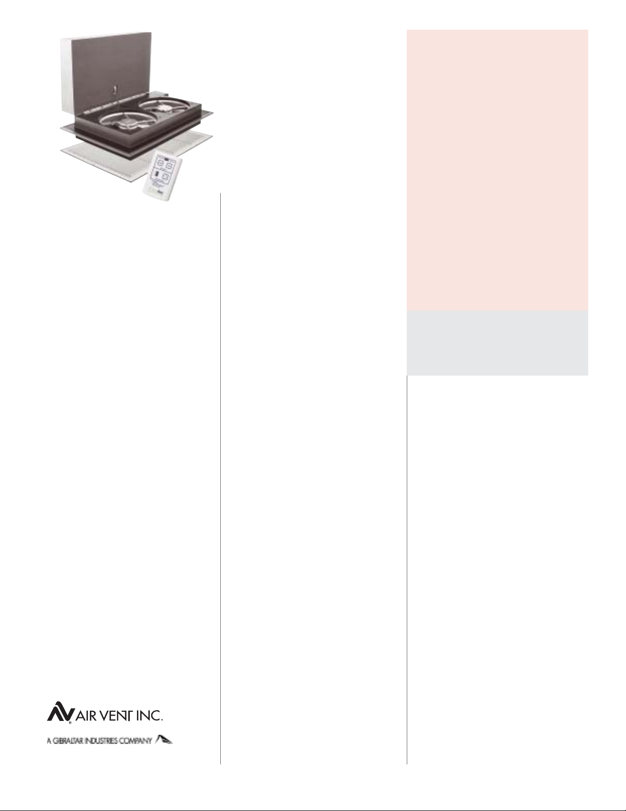
2 What Comes in the Carton
2 Step-by-Step Installation
3 Attic Ventilation Requirements
3 Electrical Requirements
3 5-Year Limited Warranty
4 Replacement Plus™ Protection
4 Operating Instructions
4 WHSP2000 Specifications
4 WHSP2000 Troubleshooting Guide
READ AND SAVE
THESE INSTRUCTIONS
SAFETY INFORMATION
Read the following safety information
before installing this Whole House Attic
Fan. Failure to follow these instructions
could result in personal injury or property
damage. If you need assistance in understanding these instructions or have
questions or comments, please call
309-692-6969.
WARNING – TO REDUCE THE RISK OF
FIRE OR ELECTRIC SHOCK, DO NOT USE
THIS FAN WITH ANY SOLID-STATE SPEED
CONTROL DEVICE OTHER THAN THOSE
INCLUDED WITH THE PRODUCT OR AVAILABLE AS AN OPTIONAL CONTROLLER
SPECIFICALLY MANUFACTURED FOR THIS
PRODUCT.
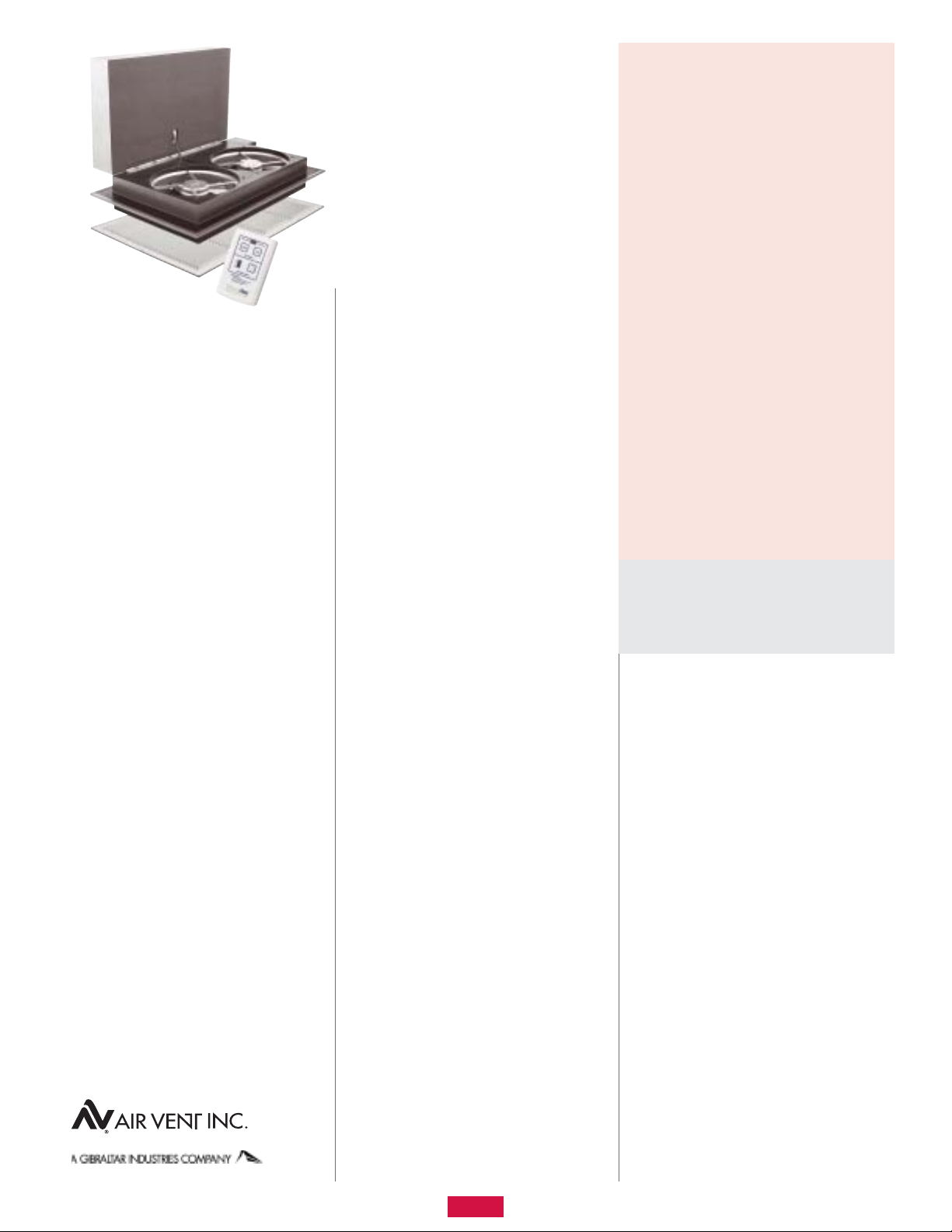
Whisper Aire
™
WHSP2000
Whole House Attic Fan
Installation
Instructions
WARNING – TO REDUCE THE RISK OF
FIRE, ELECTRIC SHOCK, OR INJURY TO
PERSONS, OBSERVE THE FOLLOWING:
•
Use this unit only in the manner intended
by the manufacturer. If you have questions,
contact the manufacturer.
•
Before servicing or cleaning the unit, switch
power off at service panel and lock the service disconnecting means to prevent power
from being switched on accidentally. When
the service disconnecting means cannot be
locked, securely fasten a prominent warning
device, such as a tag, to the service panel.
CAUTION – FOR GENERAL VENTILATING
USE ONLY. DO NOT USE TO EXHAUST
HAZARDOUS OR EXPLOSIVE MATERIALS
AND VAPORS.
CAUTION – THIS UNIT HAS AN UNGUARD-
ED IMPELLER DURING OPERATION. DO NOT
USE IN LOCATIONS READILY ACCESSIBLE
TO PEOPLE OR ANIMALS.
WARNING – TO REDUCE THE RISK OF
FIRE, ELECTRIC SHOCK, OR INJURY TO
PERSONS, OBSERVE THE FOLLOWING:
•
Qualified person(s) in accordance with all
applicable codes and standards, including
fire-rated construction, must do installation
work and electrical wiring.
•
Sufficient air is needed for proper combustion
and exhausting of gases through the flue
(chimney) of fuel burning equipment to
prevent back drafting. Follow the heating
equipment manufacturer’s guideline and
safety standards such as those published by
the National Fire Protection Association
(NFPA), and the American Society for Heating,
Refrigeration, and Air Conditioning Engineers
(ASHRAE), and the local code authorities.
•
When cutting or drilling into wall or ceiling,
do not damage electrical wiring and other
hidden utilities.
•
Ducted fans must always be vented to the
outdoors.
•
DO NOT install this unit over a tub or shower.
•
NEVER place a switch where it can be
reached from a tub or shower.
TOOLS AND MATERIALS NEEDED
•
Safety goggles
•
Tape measure or folding ruler
•
Pencil
•
Portable electric drill
•
Small drill bit (1/8-, 3/16-inch, etc.)
•
Heavy gauge (bailing) wire or wire hanger
•
Utility knife or Keyhole saw – for cutting
sheet rock
•
Saw for cutting lumber
•
2X framing lumber (length depends on
Step 5) to match cross section dimensions
of existing joist
•
Wood screws or nails for framing
(minimum 8, see Step 5)
•
1/4-inch nut driver bit
•
(3) Twist-on electrical wire connectors
•
Screwdriver with Phillips bit
•
(2) 1.5V (AA) batteries
Optional Tools and Materials–
•
Code required electrical materials
Note: Before you begin the step-by-step
installation, read the sections on “Attic
Ventilation Requirements” and
“Electrical Requirements” on page 3.
FCC REQUIREMENTS
THIS DEVICE COMPLIES WITH PART 15 OF THE
FCC RULES.
FCC ID: NGQGLD001
Operation is subject to the following two
conditions:
•
This device may cause harmful interference.
•
This device must accept any interference
received, including interference that may
cause undesired operation.
OPERATING INFORMATION
•
Keep screened windows and/or doors open
when the fan is operating to avoid drawing
carbon monoxide from furnace and water
heater flues and extinguishing pilot lights
of appliances.
•
During hot weather requiring air conditioning,
when outside air is cooler than indoors, cool
the house quicker by first operating the
whole house fan for approximately 10
minutes. Then turn off the fan and turn on
the air conditioner.
•
For operation during mild weather conditions
(when the use of air conditioning is not
required) use “Exhaust” modes to evacuate
warm air quickly.Then reduce the speed to
lower settings for maintaining whole house
ventilation.
Page 2
WHAT COMES IN THE CARTON
To make sure you have everything you need
to install your new whole house attic fan,
unpack the carton and take inventory. The
carton should contain:
(1) Fan assembly
(1) Return grill with (6) fasteners
(1) 1-inch wide x 84-inch long roll of
adhesive-backed foam
(1) Remote controller (Batteries not
included)
(6) Hex head screws for mounting fan
unit to ceiling joists
Step-by-step
installation
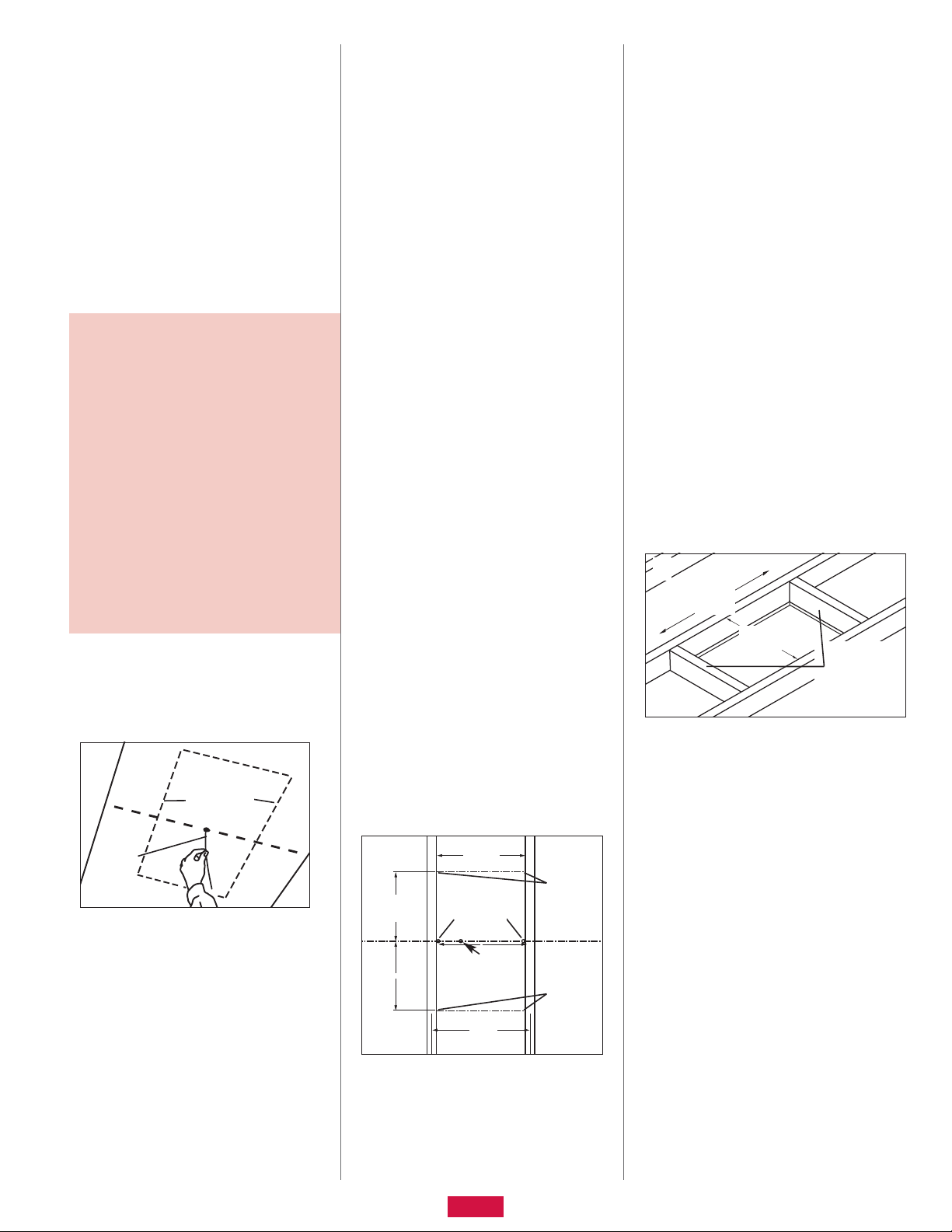
A
Proposed fan
location
Center
of
hallway
ceiling
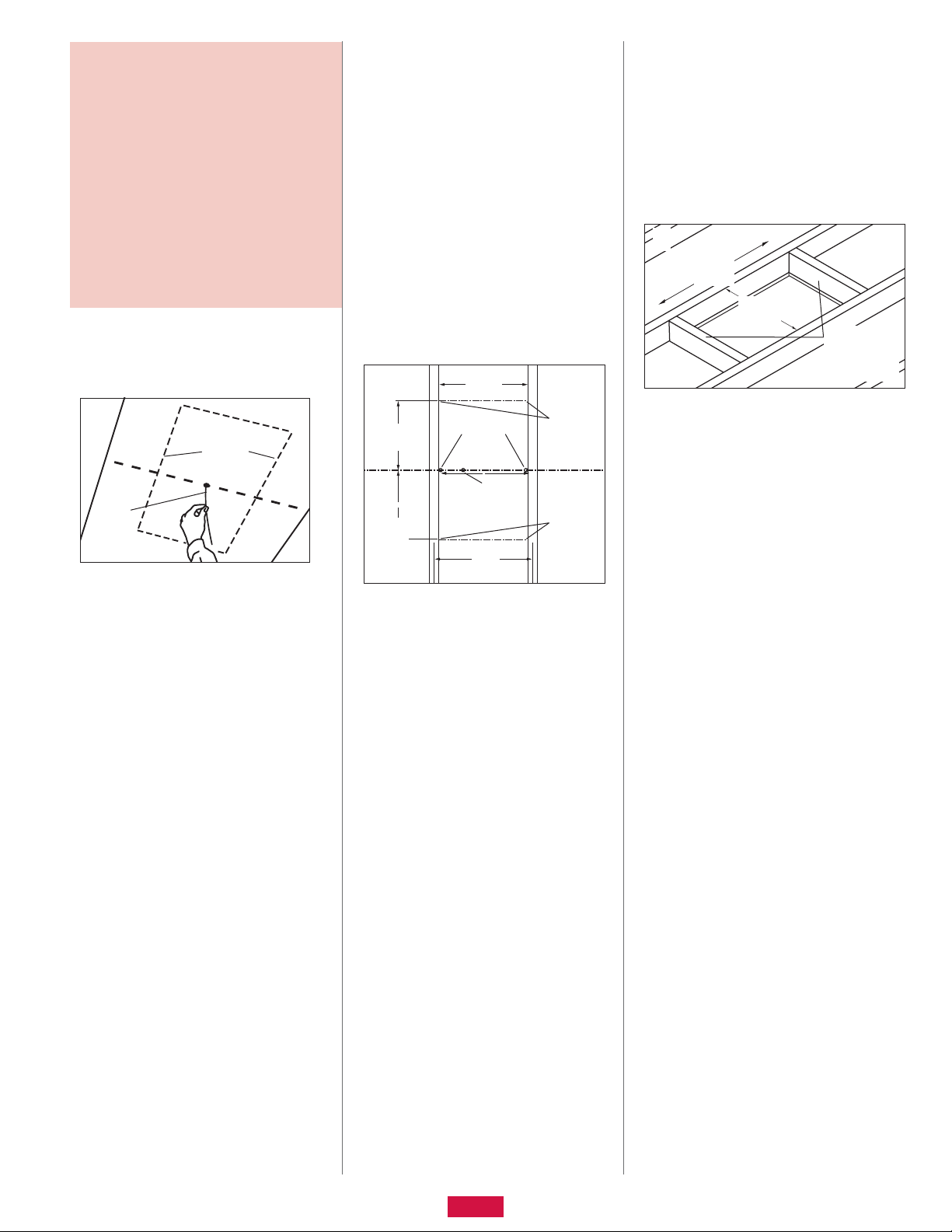
Step 1: Select a central
location for the fan
•
Your whole house attic fan is designed for
horizontal mounting on the floor of your attic,
usually above a centrally located hallway.
Note: For vertical installations, the fan should
be mounted between 16-inch OC wall studs
only. For 24-inch OC wall studs, framing will
have to be installed to simulate a 16-inch OC
wall stud situation at the desired fan location.
Installation procedures are essentially the
same as those for a horizontal installation.
•
In the hallway, find the center of the ceiling
by measuring half the distance between the
walls. Mark the spot with a pencil.
•
Drill a hole with a small bit on the ceiling
mark, and push a straight length of wire
through the hole so you can locate it in
the attic. (Illustration A)
Step 2: Investigate
the attic location
•
Go to the attic and find the hole you’ve made
in the ceiling from below.
•
Locate the joist nearest to the hole.
•
Clear the insulation between the joists at
the location of the hole (approximately 1
feet on each side of hole). Wear work
gloves to avoid skin irritation from the
insulation.
•
Check for electrical and other wires or pipes.
If any wires or pipes are in the way, you can
have them moved by a professional or pick
another location to mount the fan.
•
Check the clearance above the fan location.
There must be at least 24 inches between
the top of the fan and the roof. Providing
enough air space above the fan helps
prevent the motors from overheating and
keeps them running efficiently.
•
In addition, make sure that enough clearance
exists for the path of the shutter. To ensure
proper operation, a minimum of 4 inches
clearance is required on the hinged side
of the unit. No framing lumber, truss mem-
bers, utilities, etc. should impede the path
of the shutter.
Warning: Failure to provide sufficient shutter
clearance could result in damage to the
product.
1
/
14
B
1
/
11
4"
1
/
4")
(7
1
/
11
4"
1
/
4")
(7
2"
1
/
2")
(22
Holes at
center of
cutout sides
Hole at
center of
hallway
16"
(24")
Corner
marks for
cutout
Corner
marks for
cutout
Step 4: Cut the hole
•
Using a keyhole saw or utility knife, cut
between the four corner locations.
Note: If you are cutting from inside the attic,
you may first want to cut a hand-sized hole
at the center to allow for a place to secure
the sheet rock while cutting between the four
corners. This should help prevent the face of
the sheet rock from tearing below.
C
1
/
22
2"
1
/
2")
(14
1
/
14
2"
1
/
2")
(22
Install framing
2x’s flush with
sheet rock
cutout edges
Step 5: Install the
framing members
•
Depending on the ceiling joist spacing, cut
2X lumber to (2) 14 1/2-inch lengths for
16-inch OC joists or (2) 22 1/2-inch lengths
for 24-inch OC joists.
Note: Verify these lengths with a tape mea-
sure before cutting lumber.
•
Using nails or wood screws (not provided),
install the framing members between the
Step 3: Establish cut-out
location inside attic
Note: If the whole house fan fits through
your attic access opening, the remaining
installation steps can be performed from
inside the attic except the grill installation
(Step 8) and possibly the cutting of framing
lumber. (Step 5)
•
Select the joist bay that has the “centering”
hole which was created in Step 1, provided
that the criteria established in Step 2 are
satisfied.
Note: If ceiling joists are parallel to the length
of the hallway, it is possible that the whole
house fan will not be centered in the hallway
ceiling. Another location may need to be considered depending on personal preferences.
•
Drill two holes at the edges of the joists in
perpendicular line with “centering” hole.
(Illustration B)
Note: Make sure that the perpendicular
distance between joists is approximately
14 1/2 inches for 16-inch OC joists or
22 1/2 inches for 24-inch OC joists.
•
1
/
For 16-inch OC joists, measure 11 1/4 inches
2
(or for 24-inch OC joists, measure 7 1/4
inches) from both sides of both holes along
edges of joists and mark. This locates the
four corners of the cut-out as shown.
(Illustration B)
joists with the inside edge flush with the
exposed sheet rock edges. (Illustration C)
•
Optional Step: To help reduce the noise level
of the fan in the “Exhaust Mode” (higher
speeds), install additional 2X framing lumber
above the ceiling joists and framing members
to create a box that extends the fan further
away from the plane of the ceiling and the
grill.
Warning: It is critical to ensure that enough
clearance is available for the fan (Step 2).
In addition, the framed box should be sealed
so that attic air can not be drawn into it
through the joints.
Note: This optional step should help minimize
the possibility of blown-in insulation from
being carried by the airflow and should also
help prevent the insulation from impeding the
path of the shutter. If after this step has been
implemented and the insulation is still moved
by the flow of air, an air dam can easily be
created around the three, non-hinged sides
of the unit using either cardboard or lumber.
This air dam will force the flow of air to travel
up and over the top of the insulation.
Step 6: Mount the fan assembly
•
Using the 1-inch rolled adhesive-backed
foam, cut and apply to the underside of the
flange around perimeter of housing wall. (For
positioning: Edge of foam can be butted
against wall of housing.) Application of the
2
Page 3
foam minimizes vibration and seals possible
air passages between the living space and
the attic.
•
Using the six pre-drilled holes in the whole
house fan flange, secure the fan assembly to
the ceiling joists and framing using fasteners
provided.
Note: Orientation of the whole house fan
should allow clearance for a fully-open shutter (not only vertical distance above the fan,
but also horizontal clearance at hinged
side of the fan as described in Step 2).
Step 7: Make electrical
wiring connections
•
Refer to “Electrical Requirements” section,
page 3, for information on bringing electric
power to fan location.
•
At your home’s breaker box, turn off the electrical power to the circuit associated with the
fan. Do not turn on the power to this circuit
until you have completely finished the fan
installation.
•
From the attic, remove the cover from the
electrical wiring box on the side of the fan
housing.
•
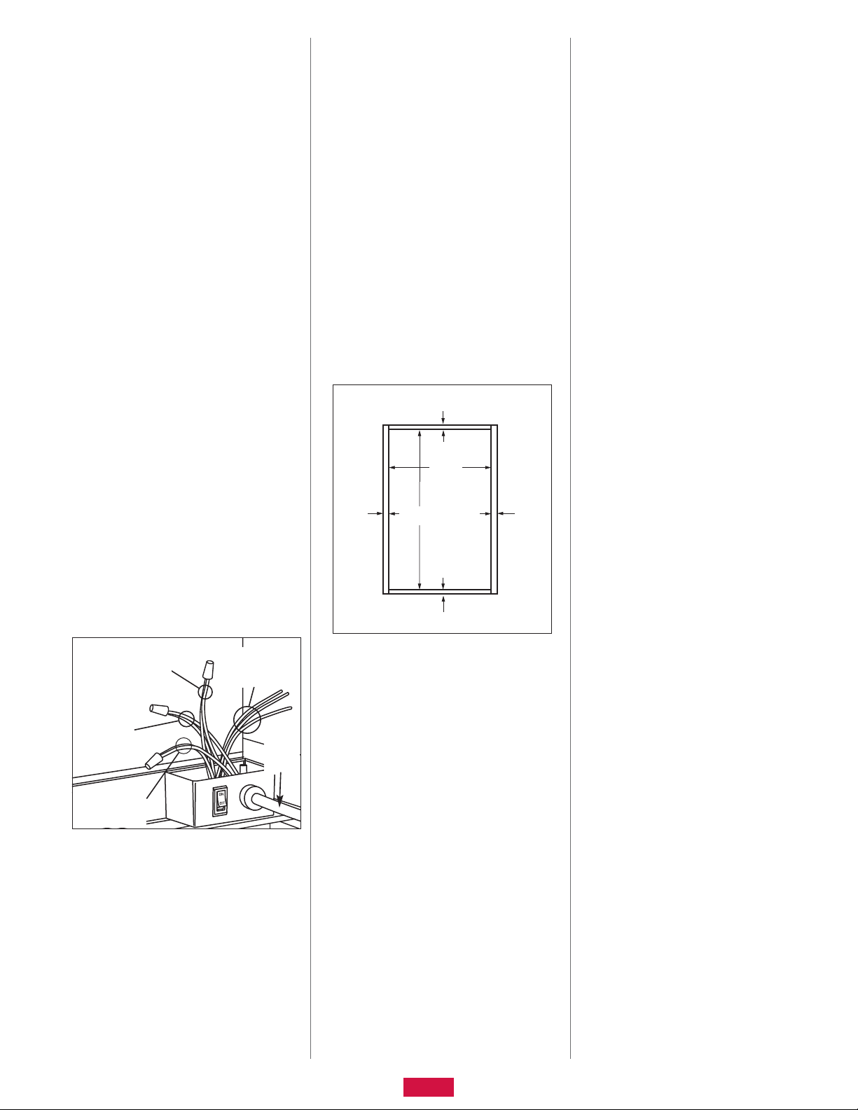
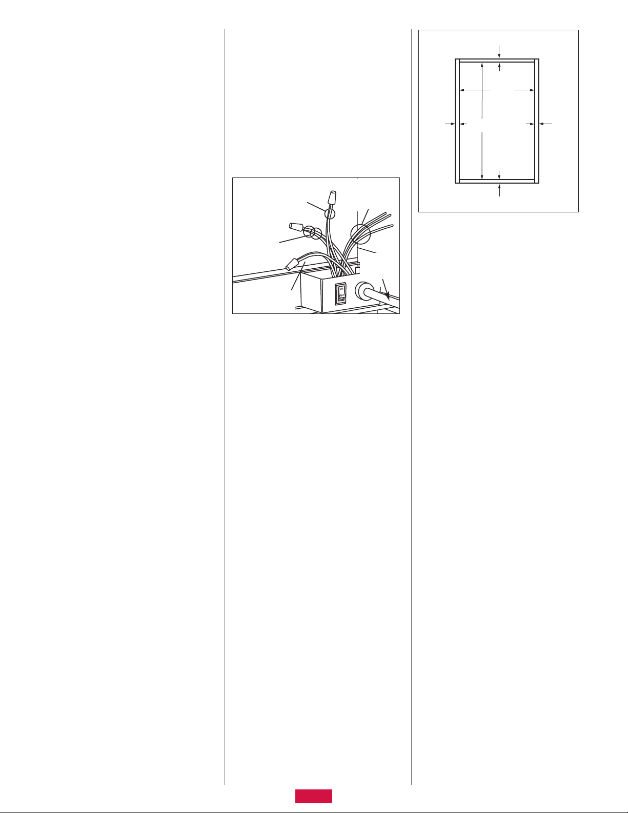
Using wire nuts make the following electrical
connections (Illustration D):
•
Hot wire from power supply (typically
black) to the fan’s black wire
•
Common (neutral) wire from power
supply (typically white) to the fan’s
white wire
•
Ground wire from power supply
(typically bare copper) to the fan’s
green wire
D
White lead &
neutral wire
from service
Black lead
& hot wire
from service
Green lead &
ground wire
from service
•
Leads (blue, red, & yellow) other than those
previously specified are only to be used for
an optional wall-mounted control. Do not remove insulation from these lead ends unless
installing the optional controller.
Warning: Failure to isolate these leads (blue,
red, & yellow) from each other and from
other conductors, including the metal wiring
box, could result in erroneous unit operation
or possibly damage to the unit.
Note: For more information about the option-
al wall-mounted controller and availability,
call 309-692-6969.
Three leads
for optional
wall controller
Power
service
from
panel
•
Push the wire connections into the unit’s
wiring box. Secure the cover to the electrical
wiring box.
•
Turn on the switch mounted to the electrical
wiring box.
•
Before leaving the attic, place the attic insulation around the whole house fan.
Step 8: Install the grill
•
Using the six fasteners provided, center and
install the grill over the opening from the
hallway. The fasteners should penetrate the
joists and framing added in Step 5.
Note: It may be necessary to trim the sheet-
rock around the perimeter of the opening to
allow for a flush installation of the grill. If so,
trim 3/4-inch from the edges of the long
sides of the sheet rock opening and 5/8-inch
from the edges of the short sides of the sheet
rock opening using a utility knife.
(Illustration E)
5
/
E
3
/
4"
8"
1
/
14
4"
1
/
22
2"
5
/
8"
3
/
4"
Step 9: Operate the fan
•
Open windows and interior doors of rooms to
be ventilated by the fan.
•
If you have a fireplace, make sure the flue
is closed.
•
At your home’s breaker box, switch on the
circuit breaker associated with the fan.
•
Insert batteries into remote.
•
Refer to the section entitled WHSP2000
Operating Instructions (page 4) for information on the functionality of the unit. A
condensed version of the operating instructions is located on the back of the remote.
ATTIC VENTILATION REQUIREMENTS
In order for the whole house fan to work properly, adequate ventilation is needed to exhaust
the hot air from the attic that the fan pulls into
the attic from your home’s living space. If your
attic is not adequately vented, the whole house
fan will shut off automatically as a result of fan
motor overload.
•
The WHSP2000 whole house fan requires a
minimum of 2.6 square feet, or approximately 384 square inches, of open attic vent area.
•
Check your attic ventilation system to make
sure that it provides at least this minimum
amount of open vent area. Typically, undereave or soffit vents are installed near the
floor of the attic, and roof louvers, gable
vents, or ridge vents are installed high in
the attic to allow air to escape. These vents
are installed to provide attic ventilation year
round, and when the whole house fan is on,
these vents provide the net free area to
exhaust it.
Remember: When measuring your vents,
obstructions such as louvers and screens
need to be factored into the open area. A
good rule of the thumb is to divide the
vent’s size in half.
ELECTRICAL REQUIREMENTS
Your whole house attic fan runs on standard
115-volt house current. Electrical installation
and wiring of the fan must adhere to the
National Electrical Code and all local codes
that apply, including fire-rated construction.
Wiring the whole house attic fan itself is a
simple procedure that most homeowners can
accomplish (see Step 7, page 3). However,
bringing the electrical power supply to the fan
requires a higher level of electrical knowledge
and skill. If you are not experienced at installing residential electrical wiring and/or are not
familiar with all national and local electrical
codes, you should hire a qualified electrician
to do the wiring for you.
5-YEAR LIMITED WARRANTY
The WHSP2000 is warranted for five (5) years
from date of purchase against defects in workmanship and materials. This warranty covers
the fan blades and motors.
If you believe any part is defective, call
1-800-527-1924 for Customer Service. If it
is determined that the product needs to be
returned to Air Vent, it must be shipped freight
prepaid to Air Vent, Inc., 3000 West Commerce
Street, Dallas, Texas 75212. If found to be defective following examination by Air Vent, Inc.,
any defective part will be replaced free of
charge and returned freight prepaid. This warranty does not cover any labor costs, including
those required for field repair or replacement
3
Page 4
or removal of any allegedly defective part. This
warranty gives you specific legal rights and
you may also have other rights, which vary,
from state to state.
REPLACEMENT PLUS PROTECTION
™
The product to which this warranty applies is
covered by Replacement Plus protection for a
period of two (2) years, provided that the product has been installed in strict accordance with
written installation instructions and in accordance with all local codes and standards,
including those pertaining to fire-rated construction. Under this warranty feature, Air Vent,
Inc., at no charge, will replace any part covered by this warranty and found to be defective
during the Replacement Plus period (The
Replacement Plus period begins when the
whole house attic fan installation is completed). Maximum liability under Replacement Plus
will be equal to the reasonable cost of the replacement part, including labor to remove the
defective part and install the replacement part.
In instances in which Air Vent, Inc., according
to the terms of this warranty has agreed to pay
the cost of labor required to replace a defective
part, Air Vent, Inc. will provide reimbursement
only upon receipt of a copy of the contractor’s
invoice or other written evidence of the completion of the work which Air Vent, Inc., at its
sole discretion, deems acceptable.
OPERATING INSTRUCTIONS
•
To start the unit, press “START.” The fan will
resume the speed setting that was last selec-
ted as indicated by the corresponding LED
which lights up momentarily when the
“START” button is depressed.
Note: Upon startup, it will take approximately
15 seconds (time for shutter to completely
open) before the processor is capable of
accepting signals from the remote control
transmitter.
•
To change speeds, press the “START” button
until the desired speed is selected as indicated by the corresponding LED on the
remote control.
Remember: It will only be possible to change
speeds after the shutter (inside of the attic)
has reached the fully open position.
•
To use the timer feature, depress the “SET
RUN HOURS” button until the desired run
time is selected as indicated by the corresponding LED which lights up momentarily
when the button is depressed. When the unit
is turned off and then back on, the timer feature defaults to manual mode.
Note: The unit must be running and the shut-
ter must be fully open before the timer feature can be activated.
•
To stop the unit at any time, depress the
“STOP” button. This interrupts power to the
fan motors and sends power to the shutter
drive motor. It will take approximately 15
seconds for the shutter to completely close
and for the processor to recognize signal
transmission from the remote control.
•
In order to conserve battery power, an 8-second timeout feature has been integrated into
the remote control software. After 8 seconds
has elapsed from the last signal transmission, any subsequent signal transmitted (by
depressing either the “START” button to
change speeds or the “SET RUN HOURS” button to change the timer selection) will be a
duplicate of the current setting. The button
used to activate the desired setting change
will need to be depressed consecutive times
until the corresponding LED of the desired
setting momentarily lights up.
WHSP2000
Troubleshooting Guide
Go to step 2.
If No
If Yes
•
Go to step 7 if fans run, but a control problem exists.
Go to step 10 if communication interference occurs.
•
•
A) Flip the switch to the ON position.
Go to step 3.
Go to step 11 for all other inquiries.
•
•
B) Repeat step 1.
Go to step 4.
•
Go to step 7.
•
power off at the circuit breaker.
A) Make the correct wiring connections with
B) Turn the appropriate circuit breaker ON.
C) Turn the junction box mounted switch ON.
D) Repeat step 1.
Go to step 5.
•
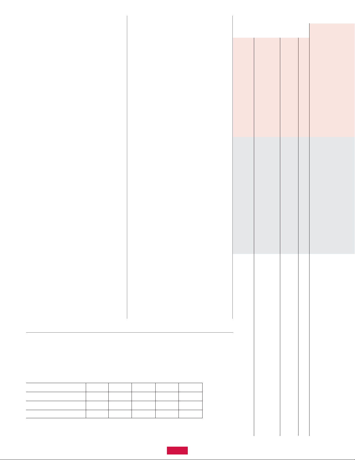
WHSP2000 SPECIFICATIONS
General Electrical Ratings 115 VAC 60 Hz
Startup Current Approx. 4.0 A
R-Value of Shutter R-25
Weight 25 lbs. (without grill)
Remote Batteries (2) 1.5 V – AA (Alkaline Recommended) NOT INCLUDED
Airflow (CFM @ 0.0" S.P.) 1290 1410 1600 1700 2200
Current Draw (A) 2.0 2.1 2.3 2.4 3.1
Power Consumption (W) 220 240 270 290 370
Fan Speed (RPM) 1665 1835 2040 2215 2830
4
Step Troubleshooting Question
1 Does the unit run?
2 Is the junction box switch in the “ON” position?
Black lead to hot leg {typically black}
White lead to common (neutral) leg {typically white}
Green lead to ground {typically bare or green}
•
•
•
electrical service?
4 Are the leads from the WHSP2000 connected correctly to the
3 Is the red LED on the side of the housing lit?
Page 5
WHSP2000 junction box to ensure continuity
exists between both ends of the hot,
common/neutral, and ground wires.
between service panel and WHSP2000 unit.
A) Flip circuit breaker to the ON position.
A) Check the wiring from the service panel to the
B) Repeat step 1.
B) Repair/connect any loose or broken connections
C) Repeat step 1.
Go to step 8.
•
panel on the back of the remote. Alkaline batteries
are suggested for best performance.
A) Replace the (2) AA batteries through the access
B) Repeat step 1.
path of the shutter.
A) Turn the unit off at the junction box switch.
B) Check to ensure there are no obstructions in the
C) Turn unit back on to determine if shutter
is functional.
to step 11.
D) If functional, repeat step 1. Otherwise, proceed
WHSP2000 units in the same structure, the DIP
switch settings need to be different for each unit.
A) To avoid interference between multiple
B) Make sure the DIP switch settings are the same for
access panel on remote.
the unit and the corresponding remote control.
D) Repeat step 1.
C) Replace film on side of housing and replace battery
Go to step 6.
•
Go to step 11 if all previous steps have
•
been explored.
Go to step 11 for inquiries into the problem.
•
Go to step 9.
•
Go to step 11 for inquiries into the problem.
•
If radio frequency interference from another
source exists, try changing the DIP switch
settings on the unit and in the remote.
These settings should be the same.
Repeat step 1.
•
ON position?
5 Is the circuit breaker which provides power to the WHSP2000 in the
the service panel at the location of the WHSP2000 junction box?
NOTE: If unsure or do not know how to check, call a licensed electrician.
6 Is there 115VAC between the hot leg and common wires from
7 Do the fans respond to signals sent from the remote control?
(Check w/remote in close proximity to unit.)
NOTE: There should be a noticeable change in sound volume coming from the
fans when a different fan speed is selected. The fans ramp between speeds and
therefore may take a few seconds to reach the new speed after a selection is made.
NOTE: The LED indicator on the side of the housing should turn off momentarily
(approximately one second) when the receiver inside of the unit senses a signal
from the remote control transmitter.
are they bright?
8 Do the red LEDs on the remote light up when a button is depressed and
when the fans are running?
NOTE: The LED indicator on the side of the housing will not be lit while power
is being sent to the shutter drive motor. Once the shutter is fully open or fully
closed, the LED indicator will be lit.
9 Is the shutter fully open to 90 degrees from the housing
5
NOTE: Each unit and remote control has been configured for communication.
There are 4 DIP switches behind the plastic film on the side of the housing
(near the LED indicator light) and also 4 DIP switches in the remote control
(behind the battery access panel). All of these are preset to the zero or off position.
removed, the DIP switches changed, and the batteries reinstalled.
10 Is there only one WHSP2000 whole house fan unit installed in the structure?
Contact Customer Service for further assistance: 1-800-527-1924
11
. NOTE: To modify the DIP switch settings, the batteries in the remote must be
Page 6
CONTENIDO
6 Información de seguridad
6 Herramientas y materiales necesarios
6 Herramientas y materiales opcionales
6 Información de la FCC
6 Información general del
funcionamiento del ventilador para
toda la casa
7 Contenido de la caja
7 Instalación paso a paso
8 Requisitos de ventilación del desván
8 Requisitos eléctricos
9 Garantía limitada de 5 años
9 Protección Replacement PlusTM
9 Instrucciones de funcionamiento
9 Especificaciones del WHSP2000
10 Guía de solución de problemas
del WHSP2000
LEA Y GUARDE ESTAS
INSTRUCCIONES
INFORMACIÓN DE SEGURIDAD
Lea la información de seguridad a
continuación antes de instalar este
ventilador de desván para toda la casa.
De no seguir estas instrucciones puede
ocasionarse lesiones personales o daños
a la propiedad. Si necesita ayuda para
entender estas instrucciones o si tiene
preguntas o comentarios, llame al
309-692-6969.
ADVERTENCIA: – PARA REDUCIR EL
RIESGO DE INCENDIO O DESCARGA
ELÉCTRICA, NO UTILICE ESTE VENTILADOR
CON NINGÚN DISPOSITIVO DE CONTROL
DE VELOCIDAD DE ESTADO SÓLIDO,
EXCEPTO EL INCLUIDO CON EL PRODUCTO
O DISPONIBLE COMO UN CONTROLADOR
ESPECIAL FABRICADO ESPECÍFICAMENTE
PARA ESTE PRODUCTO.
Whisper Aire
™
WHSP2000
Ventilador de desván
para toda la casa
Instalación
Instrucciones
ADVERTENCIA: – PARA REDUCIR EL
RIESGO DE INCENDIO, DESCARGA
ELÉCTRICA O LESIONES A PERSONAS,
HAGA LO SIGUIENTE:
•
Utilice esta unidad sólo como lo indique el
fabricante. Si tiene preguntas, póngase en
contacto con el fabricante.
•
Antes de dar servicio o limpiar la unidad,
apague ésta en el panel de servicio y
bloquee el medio de desconexión de servicio
para impedir que se active la electricidad por
accidente. Cuando el medio de desconexión
del servicio no se pueda bloquear, coloque
firmemente en el panel de servicio un
dispositivo de advertencia notorio, como
una etiqueta.
PRECAUCIÓN: – SÓLO PARA USO DE
VENTILACIÓN EN GENERAL. NO LO USE
PARA EXTRAER MATERIALES O VAPORES
PELIGROSOS O EXPLOSIVOS.
PRECAUCIÓN: – AL ESTAR EN
FUNCIONAMIENTO ESTA UNIDAD TIENE
UN IMPULSOR SIN PROTECCIÓN. NO LA
USE EN SITIOS DE FÁCIL ACCESO PARA
PERSONAS O ANIMALES.
ADVERTENCIA: –PARA REDUCIR EL
RIESGO DE INCENDIO, DESCARGA
ELÉCTRICA O LESIONES A PERSONAS,
HAGA LO SIGUIENTE:
•
El trabajo de instalación y cableado eléctrico
lo debe realizar una persona calificada, de
acuerdo con todos los códigos y normas
correspondientes, como la construcción con
protección contra incendios.
•
Para prevenir contracorrientes, necesita
contar con aire suficiente para una
combustión adecuada y para extraer los
gases a través de la chimenea del equipo
que queme combustible. Siga las pautas y
normas de seguridad del fabricante del
equipo de calefacción, como las publicadas
por la Asociación Nacional de Protección
Contra Incendios (NFPA, por sus siglas en
inglés) y la Sociedad Americana de
Ingenieros en Calefacción, Refrigeración y
Aire Acondicionado (ASHRAE, por sus siglas
en inglés) y las autoridades del código local.
HERRAMIENTAS Y
MATERIALES NECESARIOS
•
Gafas de seguridad
•
Cinta de medir o regla plegable
•
Lápiz
•
Taladro eléctrico portátil
•
Broca para taladro pequeña (de 1/8, 3/16
de pulgada, etc.)
•
Alambre de grueso calibre (achique) o
gancho para ropa de alambre
•
Navaja o segueta, para cortar paneles
de yeso
•
Sierra para cortar madera
•
Madera de entramado 2X (la longitud
depende del Paso 5) para igualar las
dimensiones transversales de la viga
existente
•
Tornillos o clavos para la madera de
entramado (mínimo 8, vea el Paso 5)
•
Punta para destornillador de 1/4 de pulgada
•
(3) Conectores para cable eléctrico trenzado
•
Destornillador con punta Phillips
•
(2) pilas de 1.5V (AA)
Herramientas y materiales opcionales:
•
Materiales eléctricos que requieren
cumplir con el código
Nota: Antes de comenzar la instalación
detallada, lea las secciones sobre
“Requisitos de ventilación del desván” y
“Requisitos eléctricos” en la página 9.
•
Al cortar o perforar el muro o el cielo raso,
no dañe el cableado eléctrico ni otros
servicios ocultos.
•
Los ventiladores con conductos siempre
deben ventilarse hacia el exterior.
•
NO instale esta unidad sobre una bañera
o ducha.
•
NUNCA coloque un interruptor donde se
pueda alcanzar desde una bañera o ducha.
REQUISITOS DE LA FCC
ESTE DISPOSITIVO CUMPLE CON LA SECCIÓN
15 DE LAS REGLAS DE LA FCC.
ID DE LA FCC: NGQGLD001
El funcionamiento está sujeto a las dos
condiciones siguientes:
•
Este dispositivo puede provocar interferencia
nociva.
•
Este dispositivo debe aceptar cualquier
interferencia recibida, incluso la que provoca
un funcionamiento indeseado.
INFORMACIÓN DE FUNCIONAMIENTO
•
Mantenga abiertas las ventanas con
mosquitero y/o puertas cuando funcione el
ventilador, para evitar atraer el monóxido de
carbono de la caldera y los tubos de humos
del calentador de agua y que se apaguen los
pilotos de los aparatos.
6
Page 7
•
En clima cálido que necesite aire
acondicionado y cuando el exterior esté más
fresco que el interior, enfríe la casa con más
rapidez prendiendo primero el ventilador
aproximadamente 10 minutos. Luego apague
el ventilador y encienda el aire
acondicionado.
•
En condiciones de clima agradable (cuando
no se necesita utilizar el aire acondicionado)
utilice los modos de "Extracción" para
evacuar el aire tibio con rapidez.
Posteriormente, reduzca la velocidad a un
ajuste más bajo para mantener la ventilación
en toda la casa.
CONTENIDO DE LA CAJA
Para estar seguro de tener todo lo necesario
para instalar su nuevo ventilador de desván
para toda la casa, desempaque la caja y
haga el inventario. La caja debe contener:
(1) Conjunto del ventilador
(1) Rejilla de retorno con seis (6)
sujetadores
(1) Rollo de espuma con adhesivo de
1 pulgada de ancho x 84 pulgadas
de largo
(1) Control remoto (no se incluyen
las pilas)
(6) Tornillos de cabeza hexagonal para
montar el ventilador en las vigas
del cielo raso
Instalación
paso a paso
A
Ubicación
propuesta del
ventilador
Centro
del cielo
raso del
pasillo
Paso 1: Seleccione una posición
central para el ventilador
•
El ventilador de desván para toda la casa
está diseñado para montaje horizontal en el
piso de su desván, por lo general arriba de
un pasillo central.
Nota: Para instalaciones verticales, el
ventilador debe montarse solamente entre
montantes de pared centrados a 16
pulgadas. Para montantes centrados a 24
pulgadas tendrá que instalar un entramado
para simular unos montantes centrados a
16 pulgadas en la ubicación deseada del
ventilador. Los procedimientos de instalación
son básicamente los mismos que para una
instalación horizontal.
•
En el pasillo, encuentre el centro del cielo
raso midiendo la mitad de la distancia entre
los muros. Marque el punto con un lápiz.
•
Perfore un orificio en la marca con la broca
pequeña y coloque un tramo recto de
alambre a través del orificio para que lo
pueda encontrar en el desván.(Ilustración A)
Paso 2: Investigue la
ubicación del desván
•
Vaya al desván y encuentre el orificio que
hizo en el cielo raso desde abajo.
•
Encuentre la viga más cercana al orificio.
•
Despeje el aislamiento entre las vigas en la
ubicación del orificio (aproximadamente 1
1/2 pies a cada lado del orificio).
Use
guantes de trabajo para evitar que el
aislamiento le irrite la piel.
•
Verifique si hay cables eléctricos o de otro
tipo o tubos. Si hubiera cables o tubos que le
estorben, puede pedir a un profesional que
los mueva o elegir otra ubicación para
montar el ventilador.
•
Verifique la distancia por arriba de la
ubicación del ventilador. Debe haber por lo
menos 24 pulgadas entre la parte superior
del ventilador y el techo. Dejar suficiente
espacio de aire le ayuda al ventilador a evitar
que se sobrecalienten los motores y les
permite funcionar con eficiencia.
•
Además, asegúrese de tener suficiente
espacio para la trayectoria de la compuerta.
Para garantizar una operación adecuada,
se necesita un mínimo de 4 pulgadas por
el lado articulado de la unidad. El paso
hacia la compuerta no debe estar impedido
por madera de entramado, vigas, servicios,
etc.
Advertencia: Si no deja suficiente espacio
para la compuerta el producto se podría
dañar.
1
/
14
B
1
/
11
4"
1
/
4")
(7
2"
1
/
2")
(22
Orificios al
centro de
los lados
del corte
Orificio al
centro del
pasillo
16"
(24")
Marcas
de las
esquinas
de corte
Marcas
de las
esquinas
de corte
Paso 3: Establezca el sitio del
corte dentro del desván
Nota: Si el ventilador cabe en la abertura de
acceso al desván, el resto de la instalación lo
puede hacer desde el interior del desván,
excepto la instalación de la rejilla (Paso 8) y
tal vez el corte de la madera de entramado
(Paso 5)
•
Seleccione el grupo de vigas que tenga el
orificio de “centrado” creado en el Paso 1,
siempre y cuando se hayan cumplido los
requisitos establecidos en el Paso 2.
Nota: Si las vigas del cielo raso van paralelas
al pasillo, es posible que el ventilador no
quede centrado en el cielo raso del pasillo.
Tal vez necesite considerar otra ubicación,
dependiendo de sus preferencias personales.
•
Perfore dos orificios en los bordes de las
vigas perpendiculares al orificio de
"centrado." (Ilustración B)
Nota: Asegúrese de que la distancia
perpendicular entre vigas mida
aproximadamente 14 1/2 pulgadas para
vigas de 16 pulgadas descentradas o 22 1/2
pulgadas para vigas de 24 pulgadas
descentradas.
•
Para vigas de 16 pulgadas descentradas,
mida 11 1/4 pulgadas (o para vigas de 24
pulgadas descentradas mida 7 1/4 pulgadas)
desde ambos lados de ambos orificios a lo
largo de los bordes de las vigas y haga una
marca. Así localiza las cuatro esquinas del
recorte, como se ilustra. (Ilustración B)
C
1
/
22
2"
1
/
2")
(14
1
/
14
2"
1
/
2")
(22
Paso 4: Corte el orificio
•
Con una segueta o navaja, corte entre las
cuatro ubicaciones de las esquinas.
Nota: Si corta desde el interior del desván,
podría cortar primero un orificio del tamaño
de su mano al centro, para tener un lugar
para fijar el panel de yeso mientras corta
entre las cuatro esquinas. Así evitará que el
frente del panel de yeso se rompa y se caiga.
Paso 5: Instalación del entramado
•
Dependiendo de la separación de las vigas,
corte la madera 2X en (2) tramos de 14 1/2
pulgadas para vigas de 16 pulgadas
descentradas o en (2) tramos de 22 1/2
pulgadas para vigas de 24 pulgadas
descentradas.
Nota: Antes de cortar la madera, verifique
estas distancias con una cinta de medir.
Con clavos o tornillos para madera (no
incluidos) instale los miembros del
entramado entre las vigas, con el borde
interior a nivel con los bordes expuestos
del panel de yeso. (Ilustración C)
•
Paso opcional: Para reducir el nivel de ruido
Instale el
entramado de
2x al ras de los
bordes de corte
del panel de yeso
7
Page 8
del ventilador en "modalidad de extractor"
(velocidades más altas) instale una madera
de entramado 2X adicional arriba de las vigas
del desván y del entramado para crear una
caja que extienda el ventilador alejándolo del
plano del desván y la rejilla.
Advertencia: Es muy importante asegurarse
de tener suficiente espacio para el ventilador
(Paso 2). Además, la caja entramada debe
estar sellada para que el aire del desván no
se pueda filtrar por las uniones.
Nota: Este paso opcional debe ayudar a
minimizar las posibilidades de que si se
aspira aislamiento no se lo lleve el flujo de
aire, y también a prevenir que el aislamiento
impida la trayectoria de la compuerta. Si
después de realizar este paso el aislamiento
todavía se mueve con el flujo de aire, puede
crear fácilmente una represa con cartón o
madera alrededor de los tres lados no
articulados de la unidad. Esta represa de
aire obligará al flujo de aire a moverse hacia
arriba y por encima de la parte superior del
aislamiento.
Paso 6: Monte el conjunto
del ventilador
•
Con la espuma en rollo con adhesivo de 1
pulgada, córtela y aplíquela a la parte inferior
de la brida y alrededor del perímetro del
muro de la vivienda. (Para la ubicación: El
borde de la espuma puede unirse a tope
contra el muro de la vivienda.) La aplicación
de la espuma minimiza las vibraciones y
sella los posibles pasos de aire entre las
áreas de estar y el desván.
•
Utilizando los orificios ya perforados en la
brida del ventilador, fije el conjunto del ventilador a las vigas y el entramado del techo
utilizando los sujetadores incluidos.
Nota: La orientación del ventilador debe dejar
espacio para una compuerta totalmente
abierta (no sólo la distancia vertical arriba del
ventilador; también espacio horizontal en el
lado articulado del ventilador, como se
describe en el Paso 2).
Paso 7: Conexiones de
cableado eléctrico
•
Consulte la sección “Requisitos eléctricos” de
la página 3. Ahí encontrará la información
para conectar la alimentación eléctrica al
ventilador.
•
En la caja de disyuntores de su casa,
desconecte la corriente eléctrica al circuito
donde estará el ventilador. No conecte la
corriente hasta terminar totalmente la
instalación.
•
Desde el desván, quite la cubierta de la caja
de cableado eléctrico por un lado del bastidor
del ventilador.
•
Con tuercas para alambre, haga las
siguientes conexiones eléctricas
(Ilustración D):
•
Conecte el cable vivo de la fuente de
alimentación (por lo general el negro) al
cable negro del ventilador
•
Conecte el cable común (neutro) de la
fuente de alimentación (por lo general el
blanco) al cable blanco del ventilador
•
Conecte el cable de tierra de la fuente de
alimentación (por lo general el de cobre) al
cable verde del ventilador
D
Cable blanco y
alambre neutro
de alimentación
Cable negro
y alambre
vivo de
alimentación
Cable verde y
alambre de tierra
de alimentación
•
Los demás cables (azul, rojo y amarillo) no
Tres cables para
el controlador de
pared opcional
Electricidad
del panel
de servicio
especificados anteriormente sólo se usan
para un control opcional montado en la
pared. No le quite el aislamiento de los
extremos de esos cables, a menos que
instale el controlador opcional.
Advertencia: Si no aísla estos cables
(azul, rojo y amarillo) entre sí y de los demás
conductores, incluso la caja de cableado
metálica, la unidad podría funcionar mal o
posiblemente dañarse.
Nota: Si desea más información acerca
del control montado en la pared y su
disponibilidad, llame al 309-692-6969.
•
Empuje las conexiones de los cables en la
caja de cableado de la unidad. Asegure la
tapa de la caja de cableado eléctrico.
•
Active el interruptor montado en la caja de
cableado eléctrico.
•
Antes de salir del desván, coloque el
aislamiento del desván alrededor del
ventilador.
Paso 8: Instale la rejilla
•
Con los seis sujetadores incluidos, centre e
instale la rejilla sobre la abertura del pasillo.
Los sujetadores deben penetrar las vigas y el
entramado agregado en el Paso 5.
Nota: Tal vez sea necesario recortar el panel
de yeso alrededor del perímetro de la
abertura para permitir que la rejilla se instale
al ras. De ser así, con una navaja recorte 3/4
de pulgada de los bordes de los lados largos
de la abertura y 5/8 de pulgada de los bordes
de los lados cortos de la abertura de panel
de yeso. (Ilustración E)
8
5
/
E
3
/
4"
8"
1
/
14
4"
1
/
22
2"
5
/
8"
3
/
4"
Paso 9: Haga funcionar
el ventilador
•
Abra las ventanas y las puertas interiores
de las habitaciones que va a ventilar el
ventilador.
•
Si tiene una chimenea, asegúrese de que
el tiro esté cerrado.
•
En la caja de disyuntores de su casa, active
el disyuntor del circuito donde está el
ventilador.
•
Coloque las pilas en el control remoto.
•
Consulte la sección “Instrucciones de
funcionamiento del WHSP2000”; ahí
encontrará información del funcionamiento
de la unidad. Al reverso del control remoto
encontrará una versión resumida de las
instrucciones.
REQUISITOS DE VENTILACIÓN
DEL DESVÁN
Para que el ventilador funcione
adecuadamente, se necesita contar
con una ventilación adecuada para extraer
el aire caliente del desván que el ventilador
extrae de los espacios de estar de su casa.
Si su desván no cuenta con una ventilación
adecuada, el ventilador se apagará
automáticamente por una sobrecarga
del motor.
•
El ventilador WHSP2000 requiere un mínimo
de 2.6 pies cuadrados, aproximadamente
384 pulgadas cuadradas, de superficie de
ventilación abierta en el desván.
•
Verifique el sistema de ventilación de su
desván para asegurarse de que cuente por
lo menos con esta superficie mínima de
ventilación abierta. Por lo general, las
ventilaciones de plafón o debajo del alero se
instalan cerca del piso del desván; las rejillas
de techo, ventilaciones a dos aguas o de
cumbrera se instalan elevadas en el desván
para permitir que escape el aire. Estas
ventilaciones se instalan para suministrar
ventilación al desván todo el año, y cuando
se encienda el ventilador, suministran el área
despejada para extracción.
Page 9
Recuerde: Cuando mida las ventilaciones,
debe tomar en cuenta, para la superficie
abierta, obstrucciones como rejillas y
mosquiteros. Una buena regla general es
dividir el tamaño de la ventilación a la mitad.
REQUISITOS ELÉCTRICOS
Su ventilador funciona con corriente casera
estándar de 115 voltios. La instalación
eléctrica y el cableado del ventilador deben
cumplir con el Código Eléctrico Nacional y
todos los códigos locales correspondientes,
como el de la construcción para prevenir
incendios.
Cablear el ventilador mismo es un
procedimiento sencillo que la mayoría de los
propietarios de casas pueden hacer (vea el
Paso 7 en la página 2). Sin embargo, llevar
la alimentación eléctrica al ventilador exige
un mayor nivel de conocimientos y habilidades
en electricidad. Si usted no tiene mucha
experiencia para instalar cableado eléctrico
residencial y/o no está familiarizado con todos
los códigos eléctricos nacionales y locales,
debe contratar a un electricista calificado para
que haga el cableado por usted.
GARANTÍA LIMITADA DE 5 AÑOS
El WHSP2000 está garantizado contra
defectos en materiales y mano de obra por
cinco (5) años a partir de la fecha de compra.
Esta garantía cubre las aspas y los motores
del ventilador.
Si cree que alguna pieza está defectuosa,
llame a Servicio a Clientes al 1-800-527-1924.
Si se determina que debe devolver el producto
a Air Vent, lo debe enviar con el flete pagado
a: Air Vent, Inc., 3000 West Commerce Street,
Dallas, Texas 75212. Si cuando Air Vent Inc. lo
examine encuentra defectos, toda pieza
defectuosa será reemplazada sin cargo alguno
y se devolverá con flete pagado. Esta garantía
no cubre los costos de mano de obra, incluidos
los que se necesiten para reparaciones de
campo o reemplazo o retiro de toda pieza
supuestamente defectuosa. Esta garantía le
otorga derechos legales específicos y usted
podría tener otros derechos, que varían de
un estado a otro.
PROTECCIÓN REPLACEMENT PLUS
™
El producto al cual se aplica esta garantía
está cubierto por la protección Replacement
Plus durante dos (2) años, siempre y cuando el
producto se instale cumpliendo estrictamente
las instrucciones de instalación y conforme a
todos los códigos y normas locales, incluidas
las relacionadas con la construcción con
protección contra incendios. Según esta
característica de la garantía, Air Vent Inc.
reemplazará sin cargo alguno toda pieza
•
cubierta por esta garantía que se encuentre
defectuosa durante el periodo de Replacement
Plus (este periodo comienza cuando se ha
terminado con la instalación del ventilador de
desván). La responsabilidad máxima según
Replacement Plus será igual al costo razonable
de la pieza de repuesto, incluida la mano de
obra, para quitar la pieza defectuosa e instalar
la pieza de repuesto.
En los casos donde Air Vent, Inc., de acuerdo
con los términos de esta garantía, acepte
pagar el costo de la mano de obra requerida
para reemplazar una pieza defectuosa, Air
Vent, Inc. hará el reembolso únicamente al
recibir una copia de la factura del contratista u
otra evidencia por escrito de que el trabajo se
concluyó y la cual, a la exclusiva discreción de
Air Vent, Inc. se considere aceptable.
Para utilizar el temporizador, presione el
botón “SET RUN HOURS” (Ajustar horario de
funcionamiento) hasta que se seleccione el
tiempo de funcionamiento deseado, tal como
lo indique el diodo LED correspondiente, el
cual se ilumina por un momento al presionar
el botón. Cuando la unidad se apague y se
encienda nuevamente, el temporizador
cambiará a modalidad manual.
Nota: La unidad debe estar funcionando y
la compuerta debe estar totalmente abierta
antes de que se pueda activar el
temporizador.
•
Para detener la unidad en cualquier
momento, presione el botón “STOP”
(detener). Esto interrumpe la energía eléctrica
a los motores del ventilador y la envía al
motor de control de la compuerta. La
compuerta tardará aproximadamente 15
INSTRUCCIONES DE FUNCIONAMIENTO
•
Para encender la unidad, presione “START”
(Inicio). El ventilador estará en el ajuste
de velocidad seleccionado la última vez,
tal como lo indique el diodo LED
correspondiente, el cual se ilumina por un
momento al presionar el botón “START.”
Nota: Al encender, tardará aproximadamente
15 segundos (tiempo para que se abra
totalmente la compuerta) antes de que el
procesador pueda aceptar señales del
transmisor de control remoto.
•
Para cambiar de velocidad, presione el botón
“START” hasta que se seleccione la velocidad
deseada, tal como lo indique el diodo LED
correspondiente en el control remoto.
Recuerde: Sólo será posible cambiar de
segundos en cerrase totalmente y en que el
procesador reconozca la transmisión de la
señal del control remoto.
•
Para conservar la potencia de las pilas, en el
software del control remoto se ha integrado
una función de tiempo muerto de 8
segundos. Después de transcurridos 8
segundos desde la transmisión de la última
señal, toda señal subsiguiente transmitida
(presionando el botón “START” para cambiar
velocidad o el botón “SET RUN HOURS” para
cambiar la selección del temporizador) será
un duplicado del ajuste actual. El botón
utilizado para activar el cambio de ajuste
deseado deberá presionarse varias veces
seguidas hasta que se ilumine el diodo LED
correspondiente al ajuste deseado.
velocidad después de que la compuerta
(dentro del desván) esté en posición
totalmente abierta.
ESPECIFICACIONES DEL WHSP2000
Clasificación eléctrica general 115 VAC 60 Hz
Corriente de arranque: Aproximadamente 4.0 A
R-Valor de la compuerta R-25
Peso 25 lb (sin rejilla)
Pilas del control remoto (2) 1.5 V tamaño AA (se recomiendan las alcalinas)
NO INCLUIDAS
Flujo de aire (CFM @ 0.0" S.P.) 1290 1410 1600 1700 2200
Consumo de corriente (A) 2.0 2.1 2.3 2.4 3.1
Consumo de potencia (W) 220 240 270 290 370
Velocidad del ventilador (RPM) 1665 1835 2040 2215 2830
9
Page 10
Guia Para Solucion de
Problemas del WHSP2000
Vaya al Paso 2.
•
Si la respuesta es No:
Si el ventilador funciona pero tiene un problema de
control, vaya al Paso 7.
Si ocurre interferencia en la comunicación, vaya al
Paso 10.
•
•
Si la respuesta es Sí:
A) Mueva el interruptor a la posición ON.
Vaya al Paso 3.
Para todas las demás consultas, vaya al Paso 11.
•
•
B) Repita el Paso 1.
Vaya al Paso 4.
•
A) Haga las conexiones de cableado correctas
Vaya al Paso 5.
Vaya al Paso 7.
•
•
desconectando el disyuntor de circuitos.
correspondiente.
de conexiones.
B) Encienda el disyuntor de circuitos
C) Encienda el interruptor montado sobre la caja
D) Repita el Paso 1.
de ON.
A) Cambie el disyuntor de circuitos a la posición
B) Repita el Paso 1.
A) Verifique el cableado desde el panel de servicio
Vaya al Paso 6.
•
Si ya investigó todos los demás pasos, vaya al
•
hasta la caja de conexiones del WHSP2000 para
asegurarse de que exista continuidad entre ambos
extremos de los cables vivo, común/neutro y
tierra.
el panel de servicio y la unidad del WHSP2000.
B) Repare/conecte toda conexión suelta o rota entre
Paso 11.
Vaya al Paso 8.
•
C) Repita el Paso 1.
Vaya al Paso 11 si tiene preguntas sobre este
problema.
•
acceso en la parte posterior del control remoto.
Para obtener el mejor rendimiento, se sugiere que
use pilas alcalinas.
A) Reemplace las (2) pilas AA a través del panel de
B) Repita el Paso 1.
Vaya al Paso 9.
•
WHSP2000 TROUBLESHOOTING GUIDE
1 ¿Funciona la unidad?
Paso Pregunta para solucionar el problema
2 ¿El interruptor de la caja de conexiones está en la posición “ON” (encendido)?
4 ¿Están los cables del WHSP2000 conectados correctamente al suministro
3 ¿Está encendido el diodo LED rojo en el bastidor?
Cable negro a pata viva {por lo general, negra}
Cable blanco a la pata común (neutro) {por lo general, blanca}
•
•
eléctrico?
Cable verde a tierra {por lo general, desnudo o verde}
•
5 ¿Está el disyuntor de circuitos que alimenta el WHSP2000 en la posición de
10
“ON” (encendido)?
6 ¿Se cuenta con 115VAC entre la pata viva y los cables del común del panel
de servicio donde está la caja de conexiones del WHSP2000?
NOTA: Si no está seguro o no sabe cómo verificarlo, llame a un electricista
certificado.
(Verifique con el control remoto muy de cerca a la unidad.)
NOTA: Debe percibirse un cambio notorio en el volumen del sonido que generan los
ventiladores al seleccionar una velocidad diferente del ventilador. Los ventiladores
avanzan gradualmente entre las velocidades y por lo tanto puede tardar algunos
segundos en alcanzar la nueva velocidad una vez que se hace una selección.
NOTA: El indicador de diodos LED del lado del bastidor debe apagarse por un
instante (aproximadamente un segundo) cuando el receptor dentro de la unidad
detecte una señal del transmisor del control remoto.
7 ¿Los ventiladores responden a las señales que envía desde el control remoto?
botón, y el color es brillante?
8 ¿Se iluminan los diodos LED en el control remoto cuando se presiona un
Page 11
WHSP2000 en la misma estructura, los ajustes de
los interruptores DIP deben ser diferentes en cada
conexiones.
obstrucciones en la trayectoria de la compuerta.
funciona la compuerta.
continúe con el Paso 11.
A) Apague la unidad con el interruptor de la caja de
B) Verifique para asegurarse de no tener
C) Encienda otra vez la unidad para determinar si
D) Si funciona, repita el Paso 1. De otra manera,
Vaya al Paso 11 si tiene preguntas sobre este
problema.
•
A) Para evitar interferencia entre varias unidades
Si existe interferencia de radiofrecuencia de otra
•
unidad.
B) Asegúrese de que los ajustes del interruptor DIP
fuente, trate de cambiar los ajustes del interruptor
DIP de la unidad y del control remoto. Estos ajustes
deben ser iguales.
sean los mismos para la unidad y para el control
remoto correspondiente.
reemplace el panel de acceso a las pilas en el
control remoto.
C) Reemplace la película al costado del bastidor y
D) Repita el Paso 1.
Repita el Paso 1.
funcionan los ventiladores?
NOTA: El indicador de diodos LED al costado del bastidor no se iluminará cuando se
envíe potencia al motor controlador de la compuerta. Una vez que la compuerta
esté totalmente abierta o cerrada, se iluminará el indicador de diodos LED.
9 ¿La compuerta está totalmente abierta a 90 grados del bastidor cuando
NOTA: Cada unidad y cada control remoto se ha configurado para tener
comunicación. Encontrará 4 interruptores DIP detrás de la película plástica al
costado del bastidor (cerca de la luz indicadora LED) y también 4 interruptores
DIP en el control remoto (detrás del panel de acceso a las pilas). Todos están
preconfigurados en cero o apagados.
NOTA: Para modificar los ajustes de los interruptores DIP tiene que quitar las pilas
del control remoto, cambiar los interruptores DIP y reinstalar las pilas.
10 ¿Sólo hay un ventilador WHSP2000 instalado en la estructura?
11 Si necesita más ayuda, póngase en contacto con Servicio a Clientes. 1-800-527-1924
11
Page 12

Air Vent, Inc.
3000 West Commerce Street
Dallas, Texas 75212
©2005 Air Vent, Inc.
Part No. 18281
 Loading...