

Page 1
(15)
(11)
(13)
(14)
(8)
(10)
(9)
(6)
(12)
(12)
(1)
(2)
(16)
FULLMIDLOW
ON
POWER
(17)(18)
(17)
(4)
(3)
(5)
(7)
VG400 and VG600 FM 4/6 Channel Systems
SECTION I Safety First for Yourself and Others.
SECTION II Federal Licensing Requirements
and Special Operating Standards for
Model Airplanes
SECTION III System Features
SECTION IV Unpacking and setting up your
AIRTRONICS VG400 or VG600
Radio Control System
SECTION V Operation Adjustments
NOTE: FOR BATTERY CHARGING
INFORMATION AND INSTRUCTIONS ON
LEARING TO USE YOUR AIRTRONICS RADIO
SYSTEM, PLEASE SEE THE AIRTRONICS
RADIO OPERATION AND INSTALLATION
INSERT.
THANK YOU FOR SELECTING AIRTRONICS
We appreciate your purchase of this new AIRTRONICS
VG400 or VG600 Radio System.
These instructions are intended to acquaint you with the
many unique features of this modern, state-of-the-art
equipment. Please read them carefully so that you may
obtain maximum success and enjoyment from its
operation
TRANSMITTER FEATURES AND FUNTIONS
The AIRTRONICS VG400/VG600 Radio Control Systems are
primarily intended for the flying of fixed wing model aircraft.
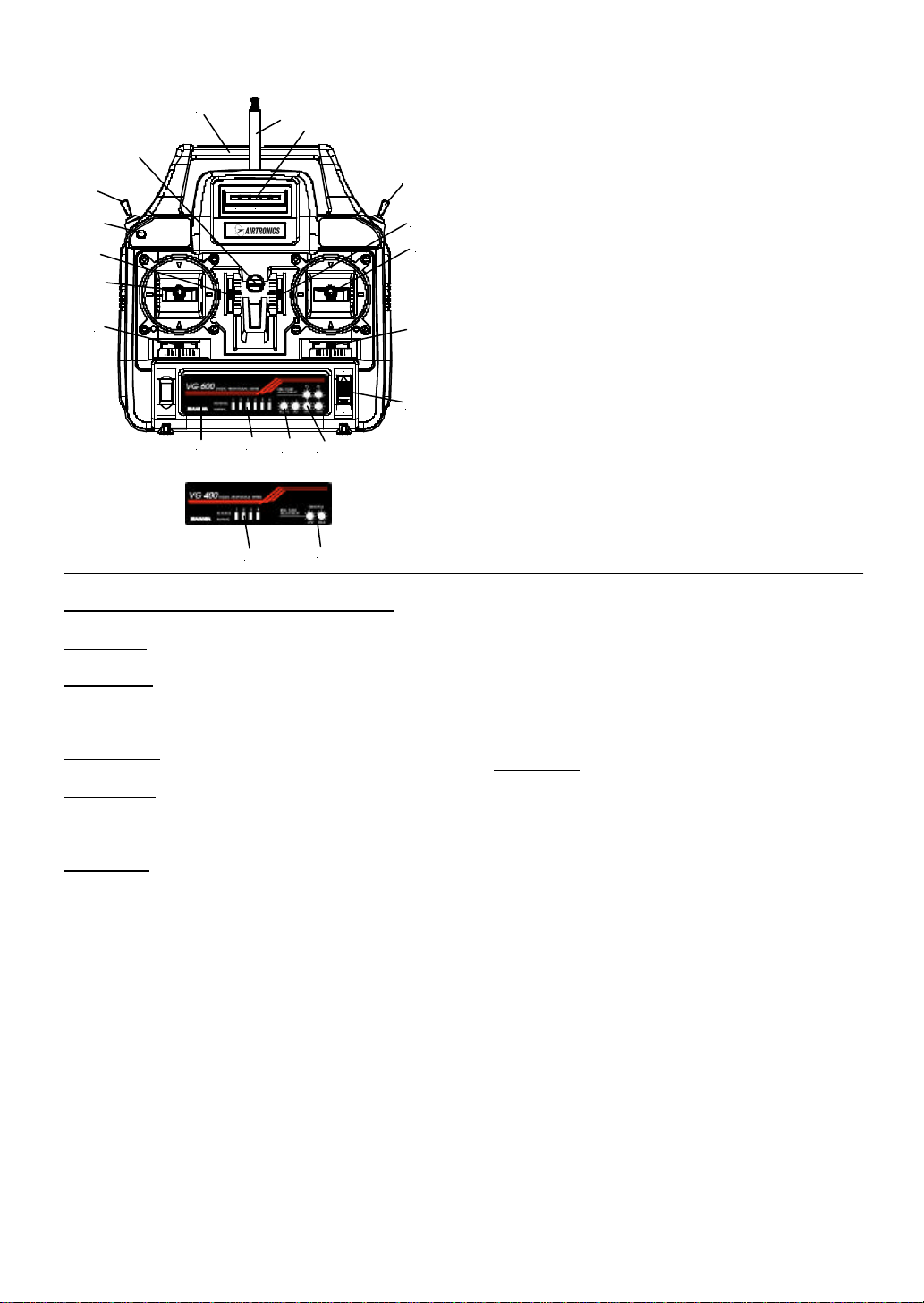
1. Retractable antenna
2. LED Scale Voltage Display
3. Control stick, horizontal-ailerons, vertical-elevator
(mode 2) Vertical-throttle (Mode 1)
4. Trim lever, elevator (Mode 2); throttle (Mode1)
5. Trim lever ailerons
6. Name Plate
7. Power Switch
8. Trim lever throttle (Mode 2); elevator (Mode 1)
9. T rim lever rudder
10. Control stick, horizontal-rudder, vertical-throttle
(Mode 2) Vertical-elevator (Mode 1)
11. Neck strap connecting hook
12. Servo reverse switches
13. Retract aux Channel (VG600 Only)
14. Trainer button
15. Carrying handle
16. 3 position aux channel flap switch (VG600 Only)
17. Throttle High and Low End point adjustments
18. Ail, Elev, Rud, Flap Servo Travel Adjusters
(VG600 Only)
We ask that you pay particular attention to the design of
the transmitter. Notice that it has been engineered for
the most natural and precise control of your choice of
flying models.
Be certain to read all of the material in this manual, as
well as the Operation and Installation insert.
SECTION I
SAFETY FIRST FOR YOURSELF, FOR OTHERS
AND FOR YOUR EQUIPMENT.
“Safety First” is more than just a slogan when operating
radio control models. Thus, we urge, especially with
respect to radio controlled aircraft that:
FOR YOUR SAFETY:
Recognize that radio controlled models are not harmless
toys and can be dangerous missiles if carelessly or
improperly flown. You are responsible because the
reliability and safe operation of the radio equipment is
largely dependent upon its proper installation and
utilization.
THEREFORE, INSTALL YOUR RADIO CONTROL
SYSTEM CORRECTLY AND BE CERTAIN YOU
CAN FLY WELL ENOUGH TO CONTROL YOUR
AIRCRAFT UNDER ALL CONDITIONS.
1
Page 2

FOR THE SAFETY OF OTHERS:
Remember that you are responsible for the safety of all
spectators and in fact, everyone that may foreseeably be
injured by your model.
DO NOT FLY where your model could injure any
person or property.
DO NOT FLY over the heads of spectators or persons in
the area of your flying field. THIS INCLUDES taking
off, actual flight and landing. KEEP EVERYONE,
except experienced and knowledgeable persons who are
assisting you in flying, away from your model even
when it is on the ground and you are preparing to fly.
DO NOT FLY unless and until you have an experienced
instructor who has completely checked out the model
and will fly the model for you and with you…until you
have learned to fly competently by yourself.
Flying is a real skill that demands patience, practice and
caution. DO NOT EXPERIMENT or run risks. Know
that you can fly safely before you fly alone. The real
pleasures and satisfactions come from flying or
operating your model with safety and competence
always in mind.
AT THE FIELD:
DO NOT FLY unless your frequency is “clear”. The
transmitting signal channel (frequency) is shown on the
transmitter and you must not turn on your transmitter
when someone is flying or operating their model on that
same frequency.
WARNING: IF YOU DELIBERATELY OR
ACCIDENTALLY TURN ON YOUR
TRANSMITTER WHILE ANOTHER MODEL IS
FLYING OR IN OPERATION, THAT MODEL WILL
GO OUT OF CONTROL. The same will happen to
yours, so observe to see if your frequency is open before
turning your transmitter on. Only one person uses a
given frequency at a time. Use your channel identifier
(frequency) flags for the frequency your system uses
and attach the appropriate flags to your transmitter
antenna. DO OBSERVE all the rules of the flying or
operating site. The Channel and frequencies associated
with them are as follows:
72 MHz (Aircraft Only)
CHANNEL and FEQUENCY (MHz)
11 72.010 MHz 31 72.410 MHz
12 72.030 MHz 32 72.430 MHz
13 72.050 MHz 33 72.450 MHz
14 72.070 MHz 34 72.470 MHz
15 72.090 MHz 35 72.490 MHz
16 72.110 MHz 36 72.510 MHz
17 72.130 MHz 37 72.530 MHz
18 72.150 MHz 38 72.550 MHz
19 72.170 MHz 39 72.570 MHz
20 72.190 MHz 40 72.590 MHz
21 72.210 MHz 41 72.610 MHz
22 72.230 MHz 42 72.630 MHz
23 72.250 MHz 43 72.650 MHz
24 72.270 MHz 44 72.670 MHz
25 72.290 MHz 45 72.690 MHz
26 72.310 MHz 46 72.710 MHz
27 72.330 MHz 47 72.730 MHz
28 72.350 MHz 48 72.750 MHz
29 72.370 MHz 49 72.770 MHz
30 72.390 MHz 50 72.790 MHz
50 72.790 MHz 55 72.890 MHz
51 72.810 MHz 56 72.910 MHz
52 72.830 MHz 57 72.930 MHz
53 72.850 MHz 58 72.950 MHz
54 72.870 MHz 59 72.970 MHz
55 72.890 MHz 60 72.990 MHz
WARNING:
The frequencies allocated for model radio exclusive;
however, they are in close proximity to other types of
radio use in certain areas. Before operating your model
check with the Federal Communications Commission
(FCC) Regional Office in your area to determine
whether there is a potential danger of interference from
other radio users. “Outside” radio interference may
cause you to lose control of your model, possibly
causing injury to yourself, to others or property damage.
SO REMEMBER:
1. DO NOT OPERATE your transmitter at the field
until you are certain your frequency is “clear”.
2. DISPLAY your frequency channel identification
flag on the antenna of your transmitter.
3. REMEMBER that channel identifier flags do not
usually state the frequency on them. Ask and be
certain. If you have an eyesight limitation or defect
such as color blindness for example, double check
to be sure of the channel flag designations.
4. Turn your transmitter on only when you are sure
no one else is using your frequency.
5. WARNING: Your model will go out of control and
may do serious injury or damage if someone else
turns on a transmitter on your frequency while you
are operating your model.
6. Respect all the rules of the flying field or site.
7. At any time during the operation of your model,
should you sense, feel or observe any erratic
2
Page 3
High Throttle
operation or abnormality, end your flight as
quickly and as safely as possible. DO NOT operate
again until you are certain the problem has been
corrected. TAKE NO CHANCES.
ADDITIONAL WARNING:
Radio controlled models are generally attractive,
exciting and inviting in looks and performance.
Therefore, realize that young persons, children and
inexperienced adults may come within the operating
range of the model, so that they may try to operate the
equipment without understanding the dangers to that
person or others. It is your responsibility to guard
against unskilled and unknowing hands for their
protection as well as for the safety of your equipment
and model.
The key to R/C pleasure is the proper use of your
system and all of the other model components. If you
fail to follow instructions, heed the warnings given,
misuse or abuse the system through improper operation
or installation, the consequences will damage your
system and may also mean injury to yourself, other
people or property of others.
AS TO YOUR EQUIPMENT:
The care you give to your equipment, and its correct
installation and operation, are the factors that spell
either safe, successful flying or injury, damage,
destruction and loss.
ACADEMY OF MODEL AERONAUTICS (AMA)
The Academy of Model Aeronautics is the leading
national organization made up of aircraft modeling
people with headquarters in Muncie Indiana. Their
address is 5151 East Memorial Dr., Muncie IN 47302.
We urge you to examine the benefits of the membership
including liability protection in the event of certain
injuries. The Academy has adopted simple and sane
rules, a few which are pertinent for radio controlled
flight as the OFFICAL AMA SAFETY CODE; abide by
these rules for your protection, the protection of others
and equipment. Excerpts are as follows:
1. I will not fly my model aircraft in competition or in
the presence of spectators until it has been proven
to be airworthy by having been previously
successfully flight-tested.
2. I will not fly my model higher than approximately
400 feet within 3 miles of an airport without
notifying the airport operator. I will give right of
way to and avoid flying in the proximity of fullscale aircraft. When necessary, an observer shall
be utilized to supervise flying to avoid having
models fly in the proximity of full-scale aircraft.
3. Where established, I will abide by the safety rules
for the flying site that I use, and I will not willfully
and deliberately fly my models in a careless and/or
dangerous manner.
4. I will have completed a successful radio equipment
ground range check before the first flight of a new
or repaired model.
5. I will not fly my model aircraft in the presence of
spectators until I become a qualified flyer, unless
assisted by an experienced helper.
6. I will perform my initial turn after takeoff away
from the pit, spectator areas, and I will not
thereafter fly over pit or spectator areas, unless
beyond my control.
7. I will operate my model using only radio control
frequencies currently allowed by the FCC. (Only
properly licensed amateurs are authorized to
operate equipment on amateur band frequencies.)
NOTE: These basic safety precautions are for your
safety, the safety of others, and of your equipment.
Consider carefully all of what has been stated and obey
all precautions as well as those appropriate to your
particular use. Good common se nse must also be used at
all times in the operation of your equipment.
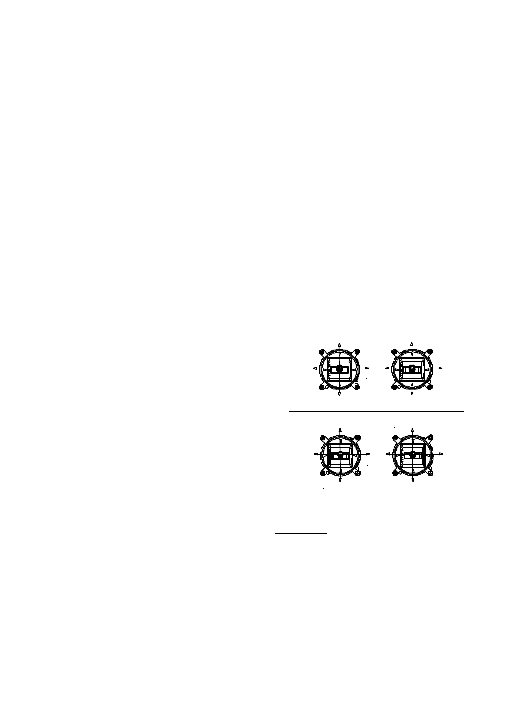
STICK CONTROLS
Down Elevator
Left
Rudder
Left
Rudder
Low Throttle
Down Elevator
Up Elevator
Mode 2
Up Elevator
High Throttle
Mode 1
Low Throttle
Right
Aileron
Right
Aileron
Fig 3
SECTION II
FEDERAL LICENSING REQUIREMENTS AND
SPECIAL OPERATING STANDARDS FOR MODEL
AIRPLANES
The Federal Communications Commission no longer
requires a license to operate an R/C model transmitter.
However, the Federal Aviation Administration has
announced guidelines for operation of model aircraft.
We are reprinting those guidelines here and encourage
your study and cooperation.
3
Page 4
1. Purpose: This advisory circular outlines safety
standards for operators of model aircraft and
encourages voluntary compliance with these
standards.
2. Background: Attention has been drawn to the
increase in model aircraft operations, and the need
for added caution in the case of free-flight and
radio controlled types to avoid creating a noise
nuisance or a potential hazard to full-scale aircraft
and persons and property on the surface.
3. Operating Standards: Modelers, generally, are
concerned about safety and do exercise good
judgment when flying model aircraft. However, in
the interest of avoiding undue criticism from
affected communities and airspace users,
COMPLIANCE WITH THE FOLLOWING
STANDARDS IS ENCOURAGED BY
OPERATORS OF RADIO CONTROLLED AND
FREE-FLIGHT MODELS.
a. Exercise vigilance for full-scale aircraft (get
other people to help if possible) so as not to
create a collision hazard.
b. Select an operating site at a sufficient distance
from populated areas to avoid creating a noise
problem or a potential hazard.
c. Do not fly higher than 400 feet above the
surface.
d. Do not operate closer than three miles from
the boundary of an airport unless permission
to do so by the appropriate air traffic control
zone has been designated, or by the airport
manager in the case of other airports.
e. Do not hesitate to ask for assistance in
complying with these guidelines at the airport
traffic control tower, or air route center
nearest the site of the proposed operations.
Director, Air Traffic Service
Federal Aviation Administration
Washington, D.C.
Under SAFETY, we encouraged your participation in
the Academy of Model Aeronautics as a member. Many
flying fields require that you be a member of the AMA
before they will allow you to use their field. They want
to know that all pilots are knowledgeable concerning the
AMA SAFETY CODE and through membership have
the liability insurance.
SECTION III
SYSTEM FEATURES
TRANSMITTER
• High Power (500 mw) internal RF Module
• Advanced Gimbal Design with control stick length
and tension adjustment
• Finely ratcheted trim controls for accurate
adjustment
• LED Voltage Display
• Servo reversing available on all channels
• Attractive chrome, and black plastic case with
internally collapsible antenna
• Throttle High and Low End Point Adjustment
• Servo travel adjustment elev, ail, flap, rud (VG600
Only)
• Trainer system compatible with our RD6000,
Radiant and other Vanguard units
• Internal Plug-in 700mah NiCd transmitter battery
• 3 Position Aux 6 channel (VG600 Only)
RECEIVER
Dual conversion 7 channel FM narrow band receiver
that meets AMA guidelines for operation at 20 kHz
channel spacing.
SERVOS
Both the VG400 and VG600 come with standard servos.
If you need more torque and or speed, we have many
servos to choose from.
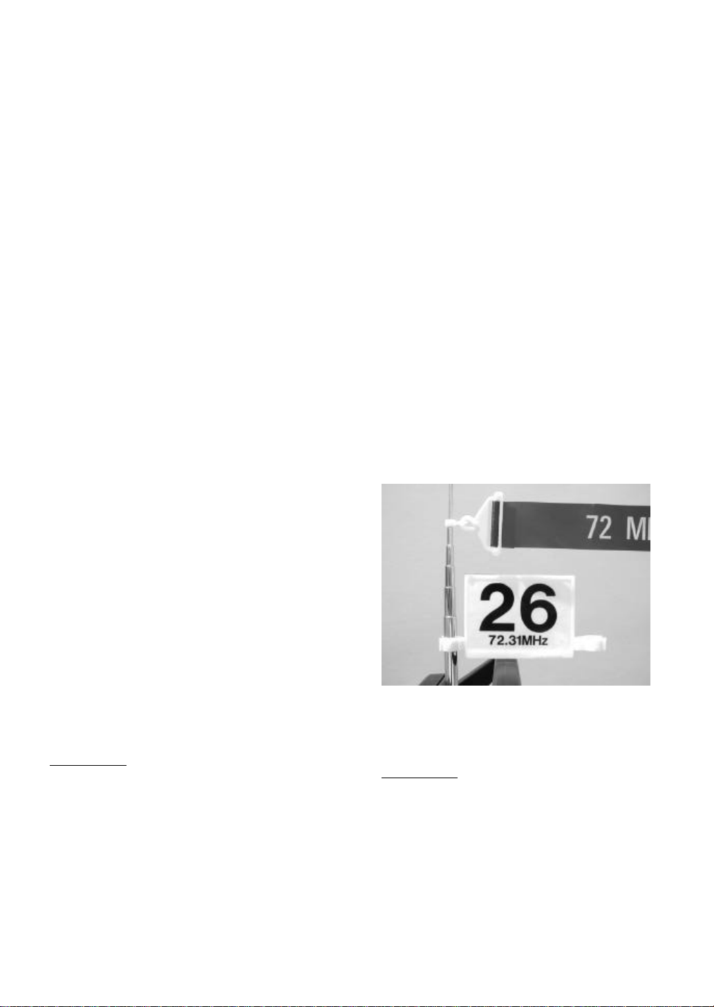
ASSEMBLY OF CHANNEL IDENTIFER:
Your Airtronics channel identification plaques and flag
are assembled to the holder as indicated in Figure 5.
Note that the plaque holder is installed on the antenna so
that it will not slide down the antenna.
Figure 5
SECTION IV
UNPACKING AND SETTING UP YOUR
AIRTRONICS VG400/VG600 FM RADIO CONTROL
SYSTEM
The packaging of your AIRTRONICS radio control
system was especially designed for the safe
transportation and storage of the components. DO NOT
DISCARD THESE CONTAINERS as they can be used
for storage or returning equipment for repair.
4
Page 5
We recommend the following procedure to familiarize
yourself with the components of your system and as
preparation for installation in your model.
1. Remove the transmitter from the package box.
2. Affix frequency channel identifier plaques to
the transmitter as shown in picture below.
3. Charge the receiver and transmitter batteries
as stated in the Installation and Guidelines
Manual. DO NOT QUICK CHARGE
BATTERIES AT ANY TIME.
4. Switch on the transmitter and note the LED
display meter indicating the unit is operating.
The LED display will light up and indicate the
state of charge of the internal NiCd battery
pack. Plug in the AC charger in the wall outlet
and connect the proper leads in the transmitter
and receiver battery and let charge for a full
24 hours for the first initial charge. After both
batteries are fully charged, note the LED
display to make sure that the FULL light is
operating properly. If the FULL LED will not
light up after a 24-hour charge, your
transmitter RF output maybe weak, this will
need to be sent to AIRTRONICS to be
checked.
5. Switch “off” the transmitter and remove all of
the other components from the foam packing
box containing your AIRTRONICS
VG400/VG600 FM radio control system.
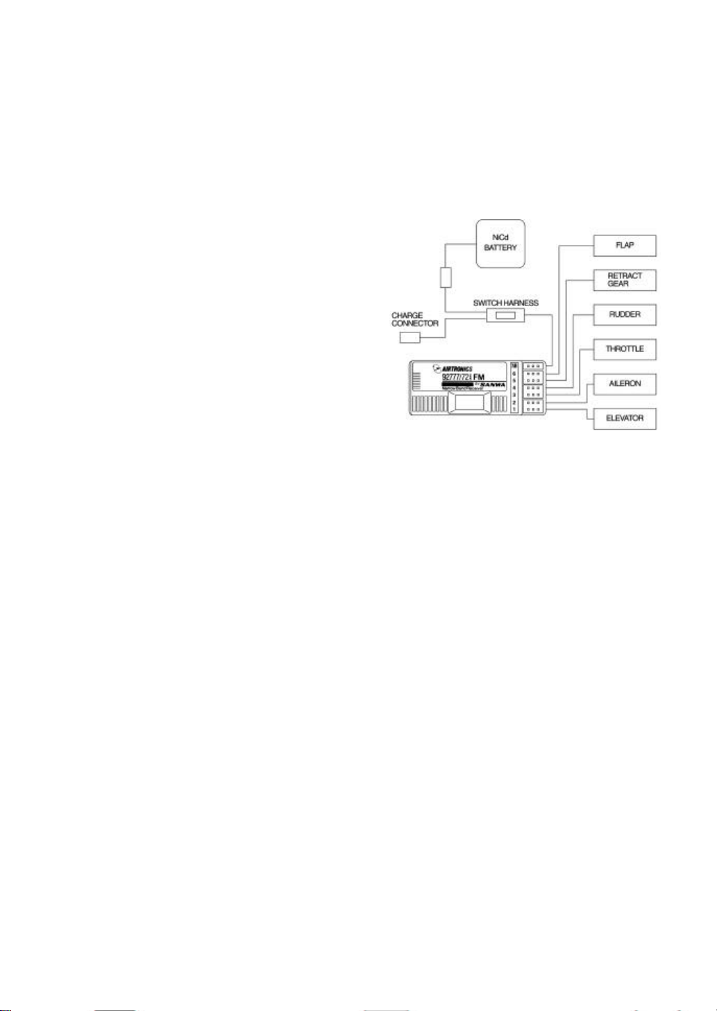
6. Figure 2 shows how to connect the
components of your system together. Note the
servo and switch harness plugs are inserted in
the receiver. This will allow you to switch the
receiver battery on and or off. At this point,
your objective is to get the system operating
on your workbench. Once connected, you
must then refer to the corresponding diagram
for your system (Figure 3), showing the
transmitter control stick’s function.
WARNING: Do not attempt to use the transmitter if the
LED lights are not visible from MID to Full.
CAUTION: IF NO LIGHTS ARE VISIBLE WHEN
YOU TURN THE TRNSMITTER SWITCH ON, THE
BATTERY PACK WITHIN THE TRANSMITTER IS
MORE LIKELY DISCHARGED. CHARGE THE
BATTERIES AS OUTLINED UNDER SECTION IV
BATTERY CHARGING, IN THE INSTALLATION
AND GUIDELINES MANUAL.
REMEMBER THAT IF A TRANSMITTERS
PERFORMANCE HAS DROPPED IT MAY FAIL TO
SEND THE SIGNALS NECESSARY TO
ADQUATELY AND SAFELY CONTROL THE
MODEL RESULTING IN A POSSIBE CRASH.
TAKE THE TIME TO LEARN THE NAMES OF ALL
COMPONENTS YOU ARE GOING TO CONNECT
AND TO IDENTIFY ALL OF THE TRANSMITTER
CONTROL STICK’S FUNCTIONS AND NAMES
ATTACHED TO THOSE FUNCTIONS.
NOTE THE FOLLOWING AT THIS POINT:
It is of no consequence at this point which servo you
plug into which function since your aim is simply to
learn and see how the system operates on your bench.
The correct channel outputs are indicated on the
receiver case.
The connectors on your AIRTRONICS radio control
system are rugged but should be handled with care. The
receiver that came with your unit is designed for the
new “Z” connector servos only. The older
AIRTRONICS connectors will not work with this new
system. You must use a connector plug adapter part
#99400Z in order to use older AIRTRONICS servos,
switch harness and or batteries.
WARNING: IF YOU CONNECT OLDER
AIRTRONICS SERVOS AND OR BATTERIES
WIT HOUT USING THE CORRECT ADAPTER, YOU
MAY SHORT OUT YOUR SYSTEM AND CAUSE
MAJOR DAMAGE TO YOUR FLIGHT PACK.
SHORTED SYSTEMS WILL NOT BE COVERED
UNDER ANY WARRANTY.
Do not attempt to force the servo plugs into the receiver;
properly align each plug and it will move into place.
The same is true of the plug leading from the receiver
battery pack and switch harness.
5
Page 6
1. Once you have followed the diagrams for
connecting the airborne components of your
VG400/VG600 FM radio control system and
you have studied and understood the diagram
illustrating the transmitter control stick
functions, you are ready to energize the
system and study its actual operation.
2. Switch on the transmitter, then switch on the
airborne package. The system is now
energized. There maybe some initial
movement in the servos even though you have
not moved the transmitter sticks. THIS IS
NORMAL. Once they have found a position,
they will stay there.
3. Now follow the diagram indicating the
transmitter’s control functions by moving
each stick and watching the reaction of the
servo or servos. Move the small black trim
levers and note the slight servo movements.
Keep these all centered through the
installation of your system in your model.
They will be used in actual flight or operation
of the model to adjust servo position
slightly…a process called “trimming”. If the
airborne system fails to operate, charge the
battery pack as outlined in the Battery
Charging Section of Installation and
Guidelines.
4. Switch off the receiver, then switch off the
transmitter. GET USED TO THIS
SEQUENCE: When turning the system off,
TURN THE RECEIVER OFF FIRST, THEN
THE TRANSMITTER. When turning the
system on, the proper sequence is to TURN
ON THE TRANSMITTER THEN THE
RECEIVER.
SECTION V
FOR OPERATION AND ADJUSTMENTS
FOR SAFE AND SUCCESSFUL OPERATION OF
YOUR RADIO CONTROL MODEL, IT IS
IMPORTANT TO CAREFULLY FOLLOW THE
INSTRUCTIONS BELOW AND OBTAIN TRAINING
IN THE OPERATION OF YOUR MODEL FROM A
WELL-EXPERIENCED INDIVIDUAL.
At this point, having followed all of the instructions,
directions and guidelines contained in the earlier
sections of this manual and having completed your
model and installed your VG400/VG600system
observing the directions and guidelines contained in the
separate manual entitled “FUNDAMENTALS AND
GUIDELINES FOR INSTALLATION OF YOUR
AIRTRONICS SYSTEM”. We present here general
instructions concerning the process of learning to use
your VG400/VG600 System. Most of what is stated is
directed toward those using the system in a powered
model aircraft. However it is equally applicable to
sailplanes.
It should be re-emphasized that before you make initial
use of your completed model, you should have one or
more persons who are thoroughly experienced in the
field of radio controlled modeling completely go over
the model prior to your use to make certain you have
properly installed your VG400/VG600 system and
followed all of the directions given in this manual as
well as the Instruction Manual. We recommend that the
individual(s) who are “checking out” your model be
shown these two manuals and that you and they review
all of the materials contained in them to make certain
that you have followed all directions and guidelines and
understand the warnings that have been given. This
should be done even if you are obtaining flight training
from experienced and competent flyers.
SERVO REVERSING:
The VG400/VG600 FM transmitters include servo
reversing on all channels. This feature makes it possible
to select the direction of the servo rotation of the
channels. Consequently, servo installation is greatly
simplified and the direction of the servo rotation
becomes unimportant. The servo reversing switches are
located in the front center of the transmitter faceplate.
THROTTLE END POINT ADJUSTMENT:
Both VG400 and VG600 have a new feature that will
allow you to set the high and low -throttle end points. By
moving the throttle stick to high-throttle, you can adjust
the TH-H adjustment clockwise to increase servo travel
or counter clockwise for less travel. For low-end
adjustment you will use the same sequence as just stated
but set the throttle stick to low throttle and use TH-L
adjuster.
SERVO TRAVEL VOLUME ADJUSTMENT (VG600
Only)
This new feature will allow you to adjust servo travel
for Aileron, Elevator, Aux Flaps and Rudder. Moving
the adjuster clockwise will increase total servo travel.
Moving the adjuster counter clockwise will decrease
total servo travel. This is very useful when setting up a
model for the first flight or you find you need more or
less control for the model aircraft.
6
Page 7
NOTE: Turning all adjusters clockwise will give 100%
maximum servo movement.
PLUG-IN CRYSTALS:
Your VG400/VG600 FM transmitter and receiver
feature plug-in crystals for ease of manufacture. The
owner should not change the FM crystals because
realignment of the transmitter and receiver FM
deviation is required following a crystal change. Failure
to do this could cause the transmitter signal to be
outside of the receivers pass band. This could cause loss
of control and a subsequent crash of your model. Do not
change crystals! If a change of operating channel is
desired, return the VG400/VG600 transmitter and
receiver to Airtronics for the desired channel change.
Channel changes are not covered under warranty and a
service charge will apply.
CONTROL STICK LENGTH AND TENSION
ADJUSTMENT:
The length and spring tension of the control sticks can
both be adjusted as required by the individual flyer.
Both procedures are simple.
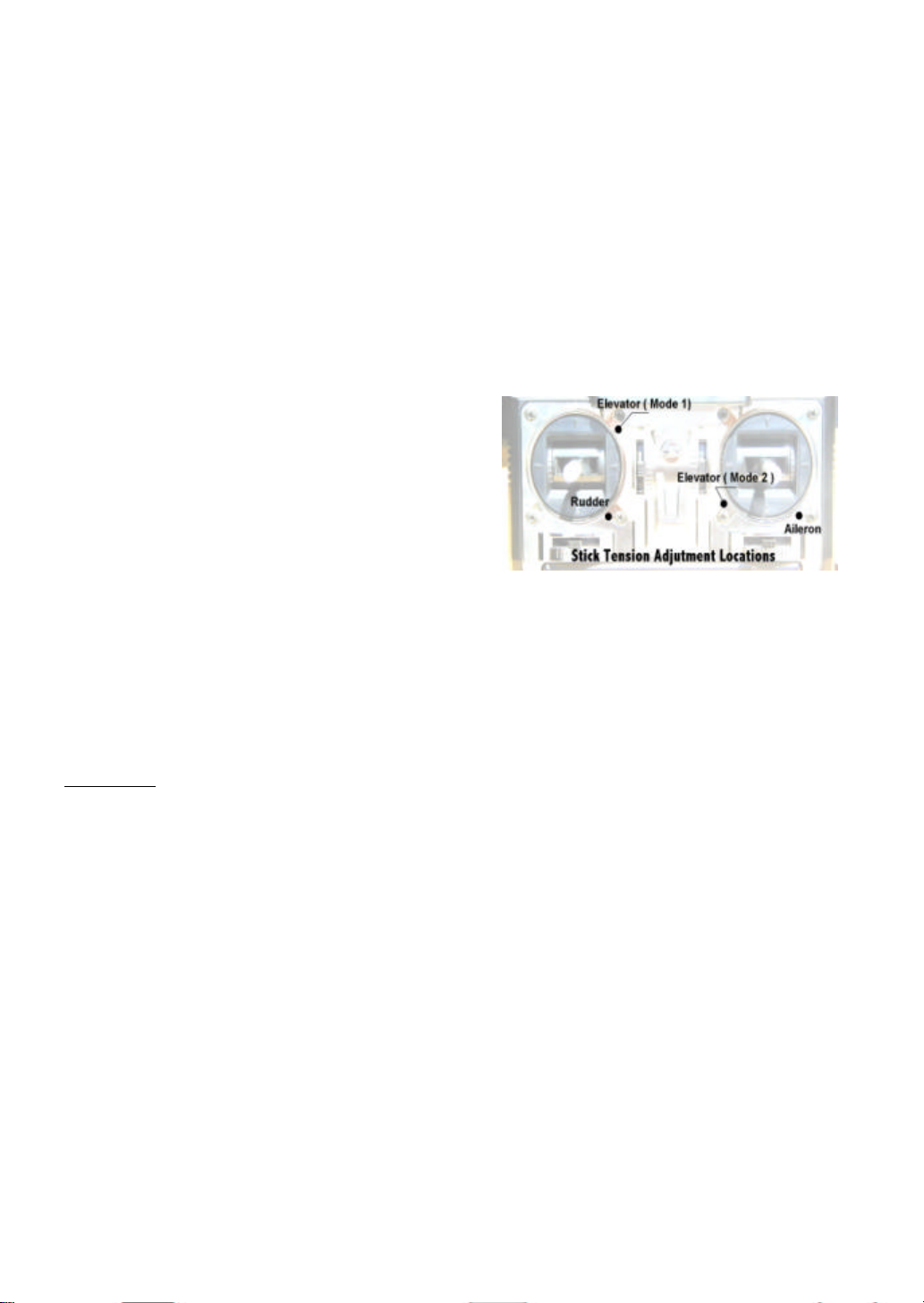
For stick spring tension, turning the adjustment screw
clockwise will increases stick tension. Turning the
adjustment screw counter clockwise will decreases or
soften stick tension. See picture below for adjustment
locations.
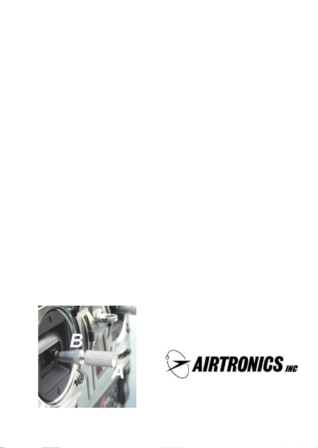
Adjusting the control stick length is even easier. To do
so, hold Part B with the fingers and unscrew Part A
counter clockwise to loosen the two pieces. Now screw
Part A in or out to the desired position and lock it in
place by screwing Part B against it. It is recommended
that at least four threads be left inside Part A at its
longest length for best results.
MASTER/TRAINER SYSTEM:
The VG400/VG600 FM transmitters have a
Master/Trainer (M/T) capability. This allows you to
connect another transmitter by use of the Airtronics
Training System Cable Part 97100. The expert-level
flyer modeler can therefore assist the beginner in
learning how to fly. See the list below for compatible
transmitters.
• VG400
• VG600
• Radiant
• RD6000
• Vanguard All
To use the Master/Trainer capability, plug the trainer
system cable into both transmitters. The transmitter that
is designated as the Master must match the receiver in
use. For the following instructions, the Master
transmitter is designated as #1 and the student
transmitter will be referred to as #2.
Turn on #1 transmitter and the model receiver switch.
Note the position of the control surfaces on the aircraft.
The #2 transmitter switch must be in the “OFF”
position, since its encoder receives its power from the
#1 transmitter. Push and hold the trainer button #14 on
#1 transmitter. #2 Transmitter now has control of the
model. Move the control sticks in the proper direction.
You can now check the neutrals of #2 transmitter to
insure they correspond to master #1 transmitter. By
turning “On and Off” the trainer button, you can see if
the #2 transmitter trims need to be adjust ed. Adjust the
trims on #2 transmitter only, moving the trims on #1
transmitter will cause the aircraft to be off trim. This
procedure is done after the aircraft has made it first trim
flights.
CAUTION: REMEMBER THAT #2 TRANSMITTER
POWER SWITCH MUST BE KEPTED IN THE OFF
POSITION.
IT IS IMPERATIVE THAT ONLY AN EXERIENCED
PILOT HELP WITH THE TRAINING OF THE
STUDENT ON #2 TRANSMITTER.
1185 Stanford Court, Anaheim, CA. 92805
Tel: (714) 978-1895
FAX: (714) 978-1540
7
www.Airtronics.net
 Loading...