

Air Techniques Peri-Pro 3 User Manual
PERI-PRO III
INTRA-ORAL
FILM PROCESSOR
USER’S MANUAL
®
A6732 ISO 13485:1996
ISO 9001:2000
Air Techniques Inc.
Hicksville, NY

CONGRATULATIONS
Since 1977, more than 70,000 Peri-Pro processors have been manufactured and sold
by Air Techniques, making it the processor of choice for the dental profession. This latest
version, the Peri-Pro III, retains the same proven rollerless transport system as earlier models. This unique system carefully guides the film through the developing process without the
image surface being touched. The Peri-Pro III also offers the same slim space saving
design, with or without a daylight loader, convenient for small office spaces. Where the new
Peri-Pro III differs from previous models is in design features that make maintenance and
operation easier and faster.
The Peri-Pro III processes film, dry-to-dry and ready to read, in only 5 minutes. To
ensure the delivery of consistent film quality, a new heating pad system, located under the
tanks, maintains uniform chemistry bath temperature.
The most significant new design features of the Peri-Pro III are an external water drain
valve in the base and a refill access door built right into the cover. With these new features,
the daily maintenance task of draining and replacing the wash water is accomplished in a
few minutes without removing the processor cover. Just turn the valve to drain the water,
open the refill access door, close the valve, and refill the water tank using the Peri-Pro III
water bottle. By following the Maintenance procedures detailed in this manual, you can
depend on years of reliable service from your Peri-Pro III processor.
TABLE OF CONTENTS
IInnssttaallllaattiioonn
Key Parts Identification ...............................................................................3
Box Contains / Unpack ..............................................................................4
Install & Assemble Processor.......................................................................4-5
OOppeerraattiioonn
Operator Controls .....................................................................................5
Processing film...........................................................................................6-7
MMaaiinntteennaannccee
Daily.........................................................................................................8
Every Two Weeks........................................................................................8-9
Quarterly ..................................................................................................10
TTrroouubbllee SShhoooottiinngg
............................................................................................11-14
SSppeecciiffiiccaattiioonnss // DDiimmeennssiioonnss
.............................................................................14
AAcccceessssoorriieess
.....................................................................................................15
2
3
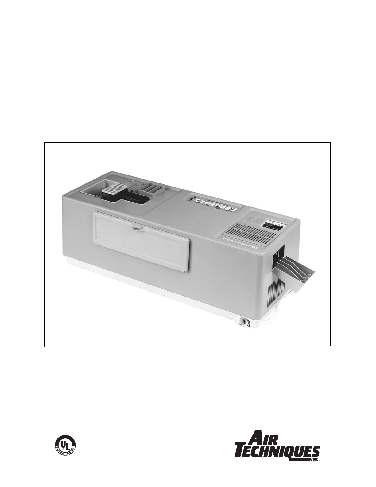
FILM INLET GRILL
FILM INLET
SHUTTER
DRAIN VALVE
KEY PARTS IDENTIFICATION
COVER
ASSEMBLY
MAINTENANCE
LABEL
OPERATOR
CONTROLS
FILM DELIVERY
RECEPTACLE
AIR OUTLET GRILL
AIR INLET GRILL
TRASH
RECEPTACLE
FILM TRANSPORT
DRYER TRANSPORT
DEVELOPER
TANK
(BLACK)
PCB & TRANSFORMER
COVER
5 AMP FUSE
AIR HOLES
TABS FOR
CARRIERS
FILM PACKET
STORAGE
FIG. 1
FIG
. 2
DRAIN HOSE
THERMISTOR
ARM
REFILL ACCESS
PANEL
DRYER HEATING ELEMENT
ACCESS PANEL
WASH TANK
(WHITE)
FIXER TANK
(RED)
Not shown: Grill inlet cover comes installed on the Film Inlet Grill

SHIPPING BOX CONTAINS:
Water bottle with flexible neck attachment
Peri-Pro III Processor base with cover -
NNoottee::
Grill Inlet Cover comes installed on the
Film Inlet Grill
Inside the processor:
Film transport
Chemistry tanks
((BBllaacckk ddeevveellooppeerr
ttaannkk;; rreedd ffiixxeerr ttaannkk;; wwhhiittee wwaatteerr ttaannkk))
Accessory boxes (3) containing:
## 9900885500
- 3 ea. Pedo (#0) Film Carrier
2 ea. Bite-wing Film (#3) Carrier
## 9900882255
- 3 ea. Anterior Film (#1) Carrier
1 ea. Occlusal Film (#4) Carrier
##
9900884400
- Film receptacle with 3 dividers
Literature kit: Manual, Warranty card
UNPACK
11..
Remove the water bottle and flexible neck
attachment from the cardboard packing
found at one end of the box.
22..
Place one hand on each side and underneath
the processor. Lift the processor out of the
carton and place it on a flat surface. Remove
the end caps and plastic bag.
33..
Remove the processor cover and set aside.
44..
Remove the accessory boxes and retain for
future use. Remove the top packing foam.
55..
Pull the cardboard insert out of the dryer rack
and set aside; lift the transport out (the transport cannot be removed until the cardboard
insert is removed first).
66..
Remove the shipping foam from the back wall
of the processor.
77..
Remove the foam cleaning pads from the
chemistry tanks and set aside.
88..
Do not remove the clips holding the water
drain tube to the perimeter of the base.
99..
Set the base on a flat, level, stable counter.
IImmppoorrttaanntt:: TThhee ssuurrffaaccee mmuusstt bbee ssttaabbllee ssoo tthhaatt
cchheemmiissttrryy ddo
oeess nnoott ssppllaasshh oorr ssppiillll..
INSTALLATION
INSTALL PROCESSOR
11.. FFiillll TTaannkkss
TThhee ttaannkkss ccaann bbee iinnssttaalllleedd iinn oorr rreemmoovveedd ffrroomm tthhee bbaassee oonnllyy wwhheenn tthhee ffiillmm ttrraannssppoorrtt iiss oouutt ooff tthhee
pprro
occeessssoorr.. IIff yyoouu iinnssttaalllleedd tthhee ttrraannssppoorrtt aafftteerr uunnppaacckkiinngg,, rreemmoovvee iitt nnooww..
FFoollllooww tthhee ttaannkk iinnssttaallllaattiioonn
aanndd cchheemmiissttrryy ffiilllliinngg sseeqquueennccee bbeellooww ttoo pprreevveenntt ccoonnttaammiinnaattiioonn ooff
cchheemmiissttrryy dduuee ttoo aacccciiddeennttaall ssppiilllliin
ngg oorr ssppllaasshhiinngg.. FFiixxeerr iinn tthhee ddeevveellooppeerr ttaannkk wwiillll ccaauussee
ccoonnttaammiinnaattiioonn..
PPeerrii--PPrroo cchheemmiissttrryy sshhoouulldd bbee a
att oorr bbeellooww 7755°°FF..
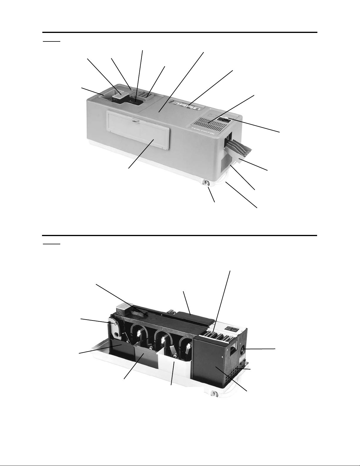
Locate the thermistor arm above and to the left of the developer
(black) tank. Carefully lift the arm up, using the finger hole, until it
locks in place. See Fig. 3.
Remove all three tanks and rinse. Note: The wash tank requires
some effort to remove the drain stem with the O-Ring from the drain
receptacle.
Install the wash tank on the right side of the base, making sure the
drain stem with the O-ring seats in the drain receptacle by pushing
down until the tank’s feet rest on the floor of the base. Fill the PeriPro III water bottle to the Fill Line (40 oz.) with room temperature
water (70° - 80°F). Attach the flexible neck to the bottle and flex into
position. Empty entire contents into the water tank.
Install the fixer tank next to the water tank, and fill with contents of the fixer bottle. Pour care-
fully to prevent splashing.
Install the developer tank on the left. Fill with the contents of the developer bottle. Lower the
thermistor arm into the tank.
If chemistry or water is accidentally spilled beneath the chemistry tanks, remove the tanks and
immediately dry the tanks, both sides of the heater plate and the depression in the base and
the area around the heater pad. Reverse the procedure to remove.
4
FIG. 3
PPOOWWEERR SSWWIITTCCHH ((AAmmbbeerr))
When the POWER switch is
turned ON it will illuminate,
indicating that there is power to
the processor and the heating
system is on. Turn the POWER
switch OFF at the end of the
day. See Fig. 6A.
TTEEMMPPEERRAATTUURREE RREEAADDYY
LLIIGGHHTT((GGrreeeenn)) // PPRROOCCEESSSS
SSWWIITTCCHH
.
When chemistry reaches its factory pre-set processing temperature of 75°F, the
RREEAADDYY
light
flashes, then remains steady,
indicating that chemistry is at
processing temperature.
Processing is initiated by turning the
PPRROOCCEESSSS
switch
OONN
.
After processing, the
PPRROOC
CEESSSS
switch is turned
OOFFFF
. The PeriPro remains ready to process
film as long as the
PPOOWWEERR
switch is left in the
OONN
position
and the green
RREEAADDYY
light is
illuminated. See Fig. 6B
RREEFFIILLLL AACCCCEESSSS DDOOOORR
Open the refill access door
when changing and refilling
water, and to check chemistry
levels at the start of the day.
This door must be closed when
processing film. It is closed
when it latches, or snaps, shut.
See Fig. 1 & 5.
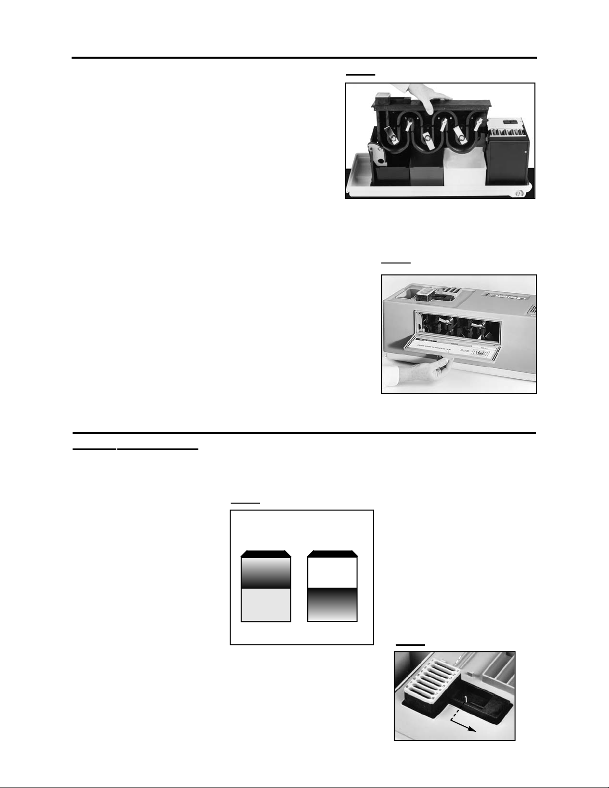
FFIILLMM IINNLLEETT SSHHUUTTTTEERR
When the shutter is slid to the
right, it latches in place. Films
drop into the transport and
begin processing automatically
when the transport arms move
into position and the shutter
opens. New batches of film can
be processed every 55 seconds.
5
FIG. 6
FIG. 7
A
B
POWER
READY WHEN LIT
PROCESS
22.. AAsssseemmbbllee PPrroocceessssoorr
Lower the film transport straight into the tanks. The
film transport must sit squarely on the cutouts found
on the top of the vertical plates to the left and right
side of the tanks.
Note: The Transport locks the thermistor into place.
Install the film inlet grill on top of the film transport.
Note that it installs one way: track 1 to the rear and
track 8 to the front of the processor.
Remove the water drain tube from the clips that
hold it to the perimeter of the processor base and push one end of this tube onto the hose
barb part of the drain valve at the right end of the processor. Place the other end of the drain
tube into a receptacle large enough (at least 45 oz.) to hold the contents of the water tank
when it is drained.
Install the processor cover onto the base with
the refill access door in front.
Snap the film dividers (optional installation) into place in the
film delivery receptacle. Hang the film delivery receptacle on
the cutout at the dryer end of the cover.
Plug the line cord into a 115V outlet.
33.. CChheecckk OOppeerraattiioonn ooff RReeffiillll AAcccceessss DDoooorr
Open the refill access door by firmly pinching the two tabs,
then pulling the door open. There will be some resistance.
Close the panel by pushing it in until it latches (snaps) shut.
OPERATION
OPERATOR CONTROLS
INSTALLATION
FIG. 4
FIG
. 5
 Loading...