

AirStage ARXB24LATH, ARXB45LATH, ARXB07LALH, ARXB09LALH, ARXB12LALH Service Manual
...
Small VRF system
for light commercial
and home use
SERVICE MANUAL


CONTENTS
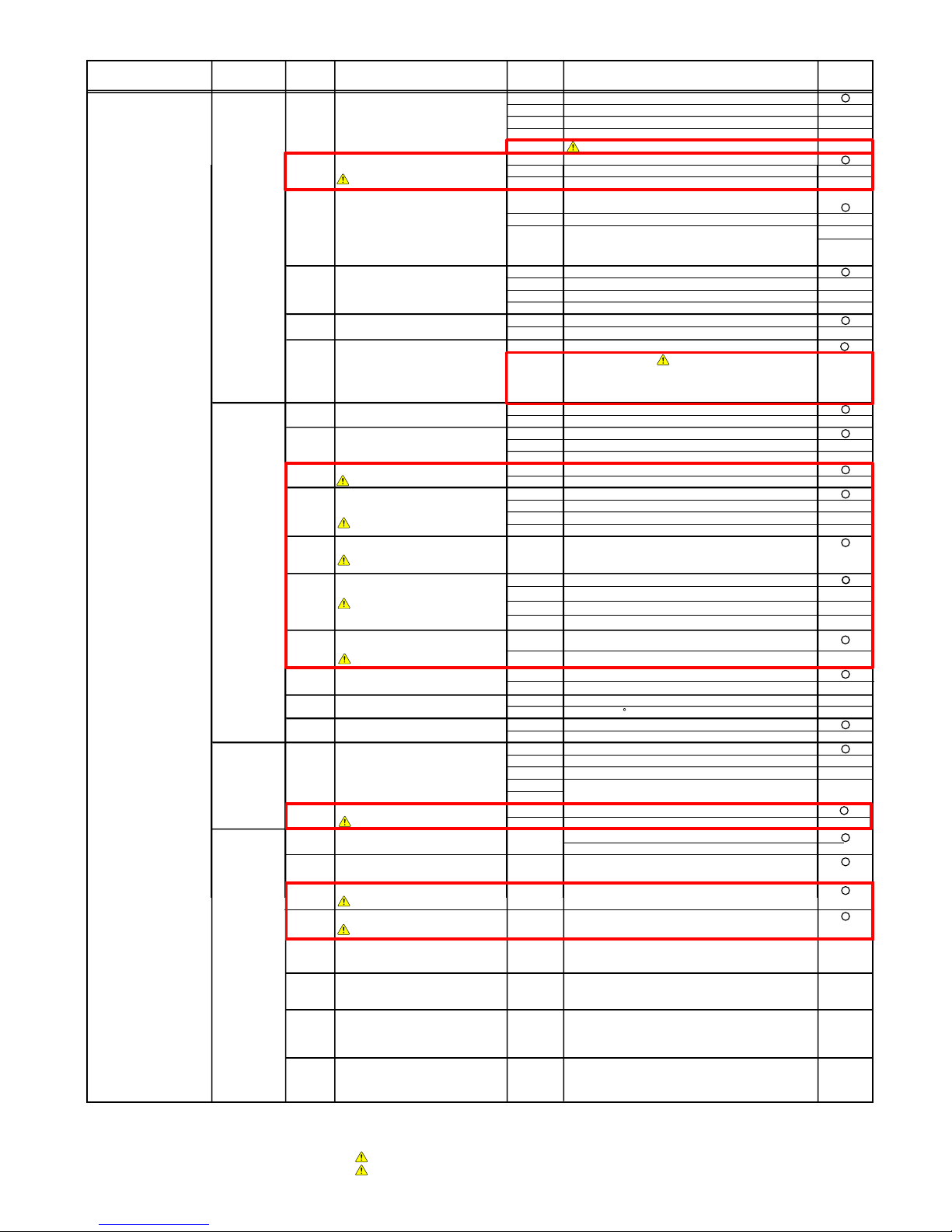
1. TEST RUN
1-3 TEST RUN CONTROL................................................................................................
1-2-1 Check Items Before Power ON............................................................................
1-2-2 Check Items After Power ON...............................................................................
1-2 TEST RUN METHOD..................................................................................................
1-1 EXECUTION PROCEDURE AND EXECUTION PRECAUTIONS.............................
1-2-4 Automatic address setting procedure for indoor units..........................................
01-01
01-03
01-03
01-04
01-07
1-2-3 Automatic address setting procedure for Signal amplifiers.................................. 01-06
01-10
1-4 Field Setting And Monitor Mode List....................................................................... 01-11
2-1 INPUT / OUTPUT LIST..............................................................................................
2. OUTDOOR UNIT OPERATION CONTROL
2-2 COMPRESSOR OPERATION....................................................................................
02-01
02-02
02-02
02-03
2-2-3 Speed Range of Start,Stop,and Operation..........................................................
2-2-2 Capacity Control.................................................................................................
02-02
2-2-1 Operation / Stop Condition.................................................................................
2-5 SPECIAL OPERATION..............................................................................................
02-09
02-09
02-10
2-5-2 Pre-Heat Operation............................................................................................
2-5-1 Oil Recovery Operation......................................................................................
2-6 PROTECTIVE FUNCTION........................................................................................
02-11
02-11
2-6-1 Protective Function List......................................................................................
2-5-3 Defrost Operation Control..................................................................................
02-10
2-3 FAN CONTROL..........................................................................................................
02-05
2-4 EXPANSION VALVE CONTROL...............................................................................
02-08
02-05
02-07
2-3-3 Low noise mode..................................................................................................
02-08
2-3-4 Other Control.......................................................................................................
2-3-1 Cooling Operation...............................................................................................
02-06
2-3-2 Heating Operation...............................................................................................
1-2-5 Indoor unit connection check procedure ............................................................. 01-08
1-2-6 Test run from the outdoor unit ............................................................................ 01-09
1-2-7 Test run from the Remote controller .................................................................... 01-09

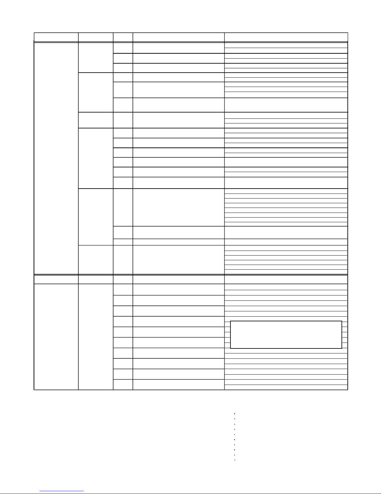
CONTENTS
3-2 MASTER CONTROL..................................................................................................
3-1-2 "AUTO" Position...................................................................................................
3-1-1 Fan Speed Setting...............................................................................................
3-1 FAN CONTROL..........................................................................................................
3. INDOOR UNIT OPERATION
3-2-1 Operation Mode Control.......................................................................................
3-2-2 Auto Changeover.................................................................................................
03-01
03-01
03-01
03-02
03-02
03-04
3-3 LOUVER CONTROL..................................................................................................
3-2-3 "COOL" Position..................................................................................................
03-05
3-2-4 "HEAT" Position..................................................................................................
03-05
03-06
3-5 DRAIN PUMP OPERATION.......................................................................................
3-4 ELECTRONIC EXPANSION VALVE CONTROL......................................................
3-6 FUNCTION..................................................................................................................
03-09
03-09
03-10
3-6-1 Auto Restart.........................................................................................................
03-10
4-1-2 Outdoor Unit Display...........................................................................................
4-1-1 Indoor Unit Display..............................................................................................
4-1 NORMAL OPERATION..............................................................................................
4. TROUBLE SHOOTING
4-2 ABNORMAL OPERATION.........................................................................................
4-2-1 Indoor Unit Display..............................................................................................
04-01
04-01
04-02
04-03
04-03
4-2-4 Remote Controller Display...................................................................................
4-2-3 Error Code List for Outdoor Unit..........................................................................
4-2-2 Outdoor Unit Display...........................................................................................
4-3 TROUBLE SHOOTING..............................................................................................
04-04
04-05
4-2-5 Error Code List for Simple and Wired Remote Controller...................................
04-07
4-2-6 Error Code List for Group Remote Controller......................................................
04-07
4-2-7 Error Code List for External Switch Controller.....................................................
04-07
+1
4-2-8 Error Code List for Signal Amplifier.....................................................................
04-07
+1
4-2-9 Error Code List for Network Convertor................................................................
04-07
+1
4-2-10 Trouble Level of System.....................................................................................
04-08
04-06
04-11
4-3-3 Trouble Shooting for Optional Parts....................................................................
4-3-2 Trouble Shooting With Error Code (OUTDOOR UNIT).......................................
4-3-1 Trouble Shooting With Error Code (INDOOR UNIT)...........................................
04-11
04-22
04-63
4-4 SERVICE PARTS INFORMATION............................................................................ 04-84
3-6-2 Icing Protection Control.......................................................................................
03-10
3-6-3 Oil Recovery Operation.......................................................................................
03-10
3-7 TIMER CONTROL......................................................................................................
03-11
3-7-1 Wireless Remote Controller................................................................................
03-11
3-7-2 Group Remote Controller..................................................................................... 03-13
3-7-3 Wired Remote Controller..................................................................................... 03-15
4-2-11 Error History Mode..............................................................................................
04-10

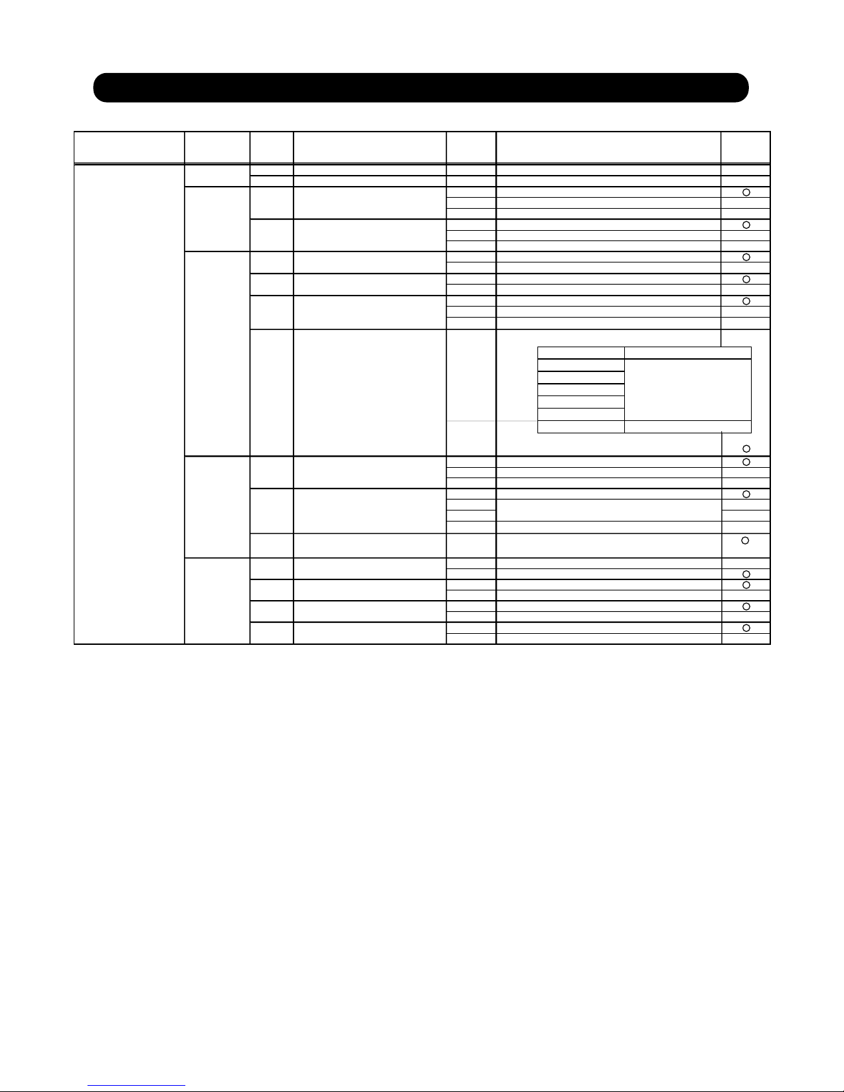
CONTENTS
5-2-1 Indoor Unit............................................................................................................
5-2 WIRING DIAGRAM....................................................................................................
5-1 REFRIGERANT CIRCUIT..........................................................................................
5. APPENDING DATA
5-3-1 Pressure sensor..................................................................................................
05-01
05-02
05-02
5-2-2 Outdoor Unit.........................................................................................................
05-15
5-3 CHARACTERISTICS OF SENSORS........................................................................
05-16
05-16
5-3-2 Thermistor resistance..........................................................................................
05-17
5-3-3 Saturation temperature and saturation pressure tables (R410A)........................
05-18
5-3-4 Temperature and pressure of refrigerant (Graph)...............................................
05-19
6. DISASSEMBLY PROCESS

1. TEST RUN

Before execution
Execution 1/2
Location decision
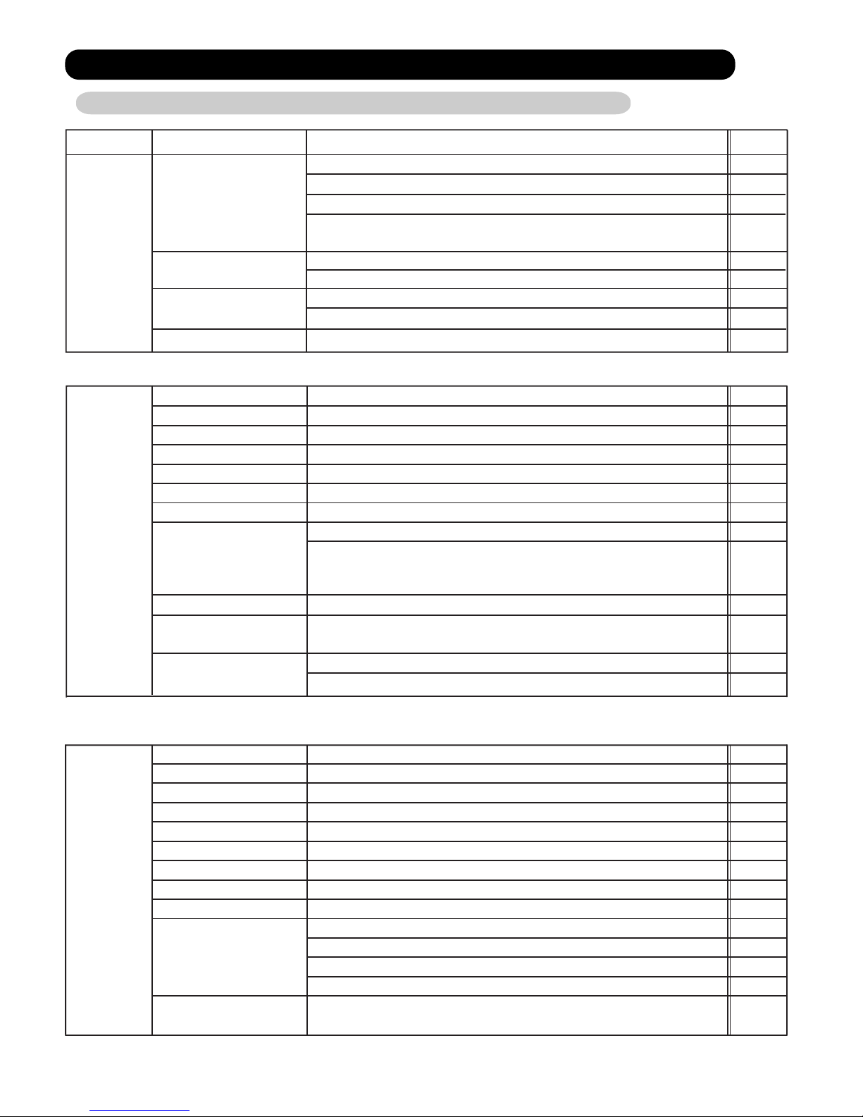
Execution procedure and precautions Reason
01-01
1-1 EXECUTION PROCEDURE AND EXECUTION PRECAUTIONS
1. TEST RUN
Sleeve and insert work
Indoor unit installation
Refrigerant piping work
Drain piping work
Duct work
Heat insulation work
Electrical work
Outdoor unit foundation work
Outdoor unit installation
Refrigerant piping connection work
Air tightness test
Vacuum drying
Use new refrigerant piping of the thickness specified by the
D&T manual.
Since R410A dedicated tools are necessary, prepare them in
advance.
Absolutely avoid use of existing piping. If use of existing
piping is unavoidable, the piping must be cleaned.
Use pipe that is not dirty inside.
Confirm the design for the piping ( Diameter, Thickness )
When the pipe is left standing, protect it.
Confirm the angle of separation tube and header correctry.
Finish flaring exactly.
Confirm the width across flats dimension and shape of flare nuts.
Always blow nitrogen while brazing.
Perform flushing before connecting the equipment.
Always make the downward slope of the drain pipe 1/100 or
greater and make the horizontal length within 20m.
Use hard polyvinylchloride pipe as the drain pipe.
Support the drain pipe between 1.5 to 2.0m.
Use pipe of 1 rank up (VP30 or greater) as central piping.
Prevention of water leakage
Foreign matter, water, etc. in the
piping will cause faulty cooling and
compressor trouble.
Incorrect pipe diameter will cause
faulty cooling
Incorrect angle of separation tube or
header will be cause poor cooling or
refrigerant noise problem
Refrigerant leakage will cause low
performance and abnormal stopping
Prevention of water leakage
Prevention of water leakage
Refrigerant leakage will cause low
performance and abnormal stopping.
Refrigerant leakage will cause low
performance and abnormal stopping.
Mixing in of vacuum pump oil by
reverse flow will cause equipment
trouble.
Always use a level and keep the indoor unit level.
If the equipment is tilted toward the drain port, install it so that the tilt
is within 10mm. Excessive tilt will cause water leakage.
Select the size of the heat insulating material according to the ambient
temperature and relative humidity of the refrigerant.
Use a heat insulating material having a heat conductivity of 0.043W/
(m.k) or less.
When making flare connections always use a torque wrench and
tighten the flare nut positively to the specified torque.
Pressurize the product with nitrogen gas up to the design pressure
and conduct a 24Hr air tightness test.
Install a vacuum pump with reverse flow check mechanism or a
reverse flow check adaptor to a conventional vacuum pump and
use.
Pump down sufficiently.
Approximately 1 hour or longer after -0.10MPa reached.
Allow to stand for approximately 1 hour after stopping the vacuum
pump and confirm that the needle does not return.
Air purging using refrigerant is strictly prohibited.
1
1
1
2
3
2
3
4
5
6
1
2
3
4
2
3
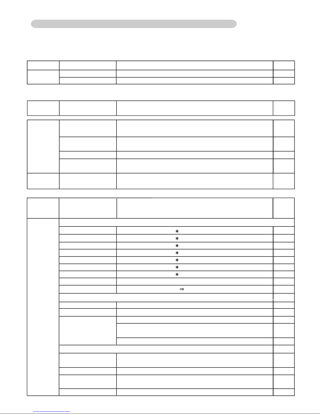
Vaccuming mode
This function is used for vacuuming the indoor unit and the connection piping.
Note: For starting Vaccuming mode, the refrigerant address setting has to be finished.
When the [vacuuming mode] is set, <Push switch setting, F3:21>
EEV of connected all indoor units opens.
So, the vacuuming indoor unit and piping becomes easier.
When the vacuuming ends, please turn off the power supply for all of the indoor units and
the outdoor unit, [vacuuming mode] is released.
*
recommend the vacuuming mode
Do not install the units in the place not recommended in the installation
manual.
The performance may drop significantly
due to the protection controlling
Use of a refrigerant other than the
specified refrigerant will invite
equipment trouble
Confirmation of Refrigerant used
Preparation of execution drawings
Confirmation of installation site
Preparation before execution
Check the characteristics of the refrigerant used and grasp the
special features of the refrigerant. If refrigerant must be charged,
always charge the refrigerant specified for the product.
*Confirm the product design pressure. < R410A 4.20MPa >
Prepare the design for the system
Secure the necessary pressure
resistance.
When performing piping work, observe the following items so that the
inside of the piping is clean and air tight.
7
8
01-02
[Note] Perform in the power OFF state.
Execution 2/2
Set according to the length of the connection piping.
Set to "Standard (40 to 65m)" at the factory.
Set using the push button SW on the outdoor unit main PCB.
< Refer to the Page 01-16 Setting mode F2-00 >
Set the pipe length to be the nearest indoor unit from the outdoor unit
Set the refrigerant circuit address and indoor unit address.
Can be set by rotary SW on the indoor unit PCB ( Main PCB or Switch
PCB) or from a remote controller or from a push button SW on the
outdoor unit Main PCB < Automatic address setting,
Refer to the Page 01-07 Setting mode F3-11>
Initial setting
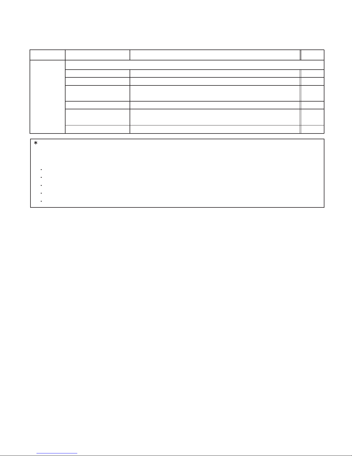
Gas leak test
Use an R410A dedicated leak tester to check for gas leaks.
1
2
3
Confirm the additional refrigerant amount with the installation
manual, etc.
Always take the R410A refrigerant from the cylinder liquid phase
and charge it using the gas phase.
(Do not lay a cylinder with siphon pipe on its side.)
Use an R410A dedicated gauge manifold and charging hose.
Charge refrigerant using the liquid pipe.
When the defined amount of refrigerant cannot charge using the
liquid pipe, charge refrigerant using the gas pipe while opearing
the cooling test run.
Charge refrigerant bit by bit with cautious operation of valve
for the liquid refrigerant back prevention.
If taken from the air phase, since the
composition of the refrigerant which is
charged will change, low performance
and abnormal stop will occur easily.
Prevent erroneous sealing in of
refrigerant.
A leak tester for other than R410A
cannot detect leaks.
Set the refrigerant circuit address.
ROTARY SW: REF ADX10, X1
4
Turnover & explanation of operation
Address setting for Indoor unit
Test run & adjustment
Piping length setting
Addition refrigerant charging
5
Indoor unit connection check
[Note] Perform setting by push button SW on the outdoor unit Main PCB in the power ON state
after all indoor units have stopped operation.
When setting the address of Signal amplifier, please refer to the
installation manual of the signal amplifier.
The address setting can be set by automatically from 1 outdoor unit
on the network. < Refer to the Page 01-06 Setting mode F3-10 >
Address setting for Signal Amp
- When using signal Amps -
[Note] Manual setting: Set the rotary SW on the PCB in the power OFF state.
Automatic address setting:
Perform setting by push button SW on the outdoor unit Main PCB in the
power ON state after all indoor units have stopped operation.
[Note] Perform in the power ON state after all indoor units have stopped operation
[Note] Manual setting: Set the rotary SW on the PCB in the power OFF state.
Automatic address setting:
Perform setting by push button SW on the outdoor unit Main PCB in the
power ON state after all indoor units have stopped operation.
Dual address setting No. is not
allowed in one network.
When the setting is not same as the
real piping length, the system may
not work correctly.
Dual address setting No. is not
allowed in one network.
Dual address setting No. is not
allowed in one network.
Normal operation will not be possible
without performing the indoor unit
connection check.
Before starting the system, check on the number of indoor units and
the total capacity.
< Refer to the Page 01-08 Setting mode F3-12 >
Execution procedure and precautions Reason
1
2
Confirm the DIP SW setting
SET 1: Factory setting, SET 2 : All OFF, SET 3 : All OFF,
SET 4: Factory setting
If the DIP SW setting is wrong, the sys tem may not work correctly
3
Confirm the Terminal resister setting
SET 5-4 OFF: Disable, ON: Enable
If the Terminal resister setting is wrong,
the system may detect transmission
error
If the pipe length is set as the farthest
indoor unit, the nearest operating
indoor unit may be stopped the
operation by the icing up protection
as by over cooling.
Outdoor unit: 32A ( AJ*A36,45,54LALH )
Indoor unit: 20A
Leakage current: 30mA 0.1sec or less
Install a breaker (Included with Earth Leakage Circuit Breaker) in accordance
with the related laws and regulations.
Outdoor unit: 6mm
2
2 wires + Ground 4mm
2
Indoor unit: 2.5mm2 2 wires + Ground
Outdoor unit side: AC 230V (220-240V)
Indoor unit side: AC 230V (220-240V)
Use crimp-type terminals with insulating sleeves for stranded conductor cable
Power
source
Shall be no scratches, deformation, etc. (Be careful of deformation of the front panel)
Shall be checked and entered in the check sheet.
Shall be checked and entered in the check sheet.
Connection points check & loose terminal block screws check
0.33mm2, shielded wire used (22AWG)
Connection points check & loose terminal panel screws check
Check whether or not the heat insulation material is installed without a gap.
DIP SW SET1, SET4 : Factory setting, SET2,SET3, SET5-1,2,3: ALL OFF
Terminal resistor setting SET5 - 4 OFF: Disable, ON: Enable
Check the resistance value for each network segment
Refer to the installation manual 7.7
Refrigerant circuit address setting (SET : REF AD x10 and REF AD x1)
Comparison of calculated value and value written on electrics box. Entered in check sheet.
Refer to the installation manual 8.3.2
Gas pipe: fully open
Liquid pipe: fully open
There shall be no scratches, deformation, tilting, etc.
Shall be checked and entered in the check sheet.
Shall be installed positively.
Connection points check & loose terminal panel screws check
0.33mm2, shielded wire used (22AWG)
Connection points check & loose terminal panel screws check
0.33mm
2
Connection points check & loose terminal panel screws check
Check whether or not the heat insulation material is installed without a gap.
Refrigerant circuit address (REF AD)
Indoor unit address (IU AD)
At automatic address setting, IU AD/REF AD shall be [0].
Remote controller address (RC AD)
Function setting (Remote controller custom code/ external input switching/
auxiliary heater ON-OFF)
Indoor
unit
Outdoor
unit
Judgement standard
Check
Check contentsProcedure
1-2 TEST RUN METHOD
1-2-1 Check Items Before Power ON
01-03
[Note] If operated with the 3-way valve closed, the oil discharged from the compressor will not be returned
and will lead to trouble.
Circuit breaker capacity
Type of power source
wiring
Supply power source
Appearance
Serial No.
Drain cap installation
Power source wiring connection
Type of communication line
Communication line connection
Type of remote controller wiring
Remote controller wiring connection
Connection piping
Rotary SW setting
DIP-SW setting
Appearance
Serial No.
Outside air temperature
Power source wiring connection
Type of communication line
Communication line connection
Connection piping
DIP-SW setting
Rotary SW setting
Additional refrigerant amount
3-way valve
Wiring on terminal blocks
Addresses shall be assigned to all indoor units / Signal amps.
Check for unset or duplicated addresses.
< For the setting, Refer to the page 01-06, 07 >
All the indoor units in the same refrigerant
circuit
shall enter the coolingtest run
state.
The outdoor units corresponding to the operation capacity of the indoor
units shall operate. < Test operation procedure, Refer to the page 01-09,10 >
Cooling
test run
All of the
indoor units
operation
(after 30 mins)
Automatic address setting
Address read
Outdoor unit circuit breaker ON
Indoor unit circuit breaker ON
Check lighting of Main PCB LED101 and 7-segment display.
Check whether or not indoor unit OPERATION and TIMER lamps flash alternately.
Address
setting/
check
There shall be no Error information on the 7-segment display on the Main PCB.
Between L - N AC230V (220-240V)
These shall be no abnormal sound or abnormal vibration.
The outdoor fan shall not make a moaning sound.
There shall be no discharge air leaking from the outdoor duct.
There shall be no pipe chattering sound or flute sound generated.
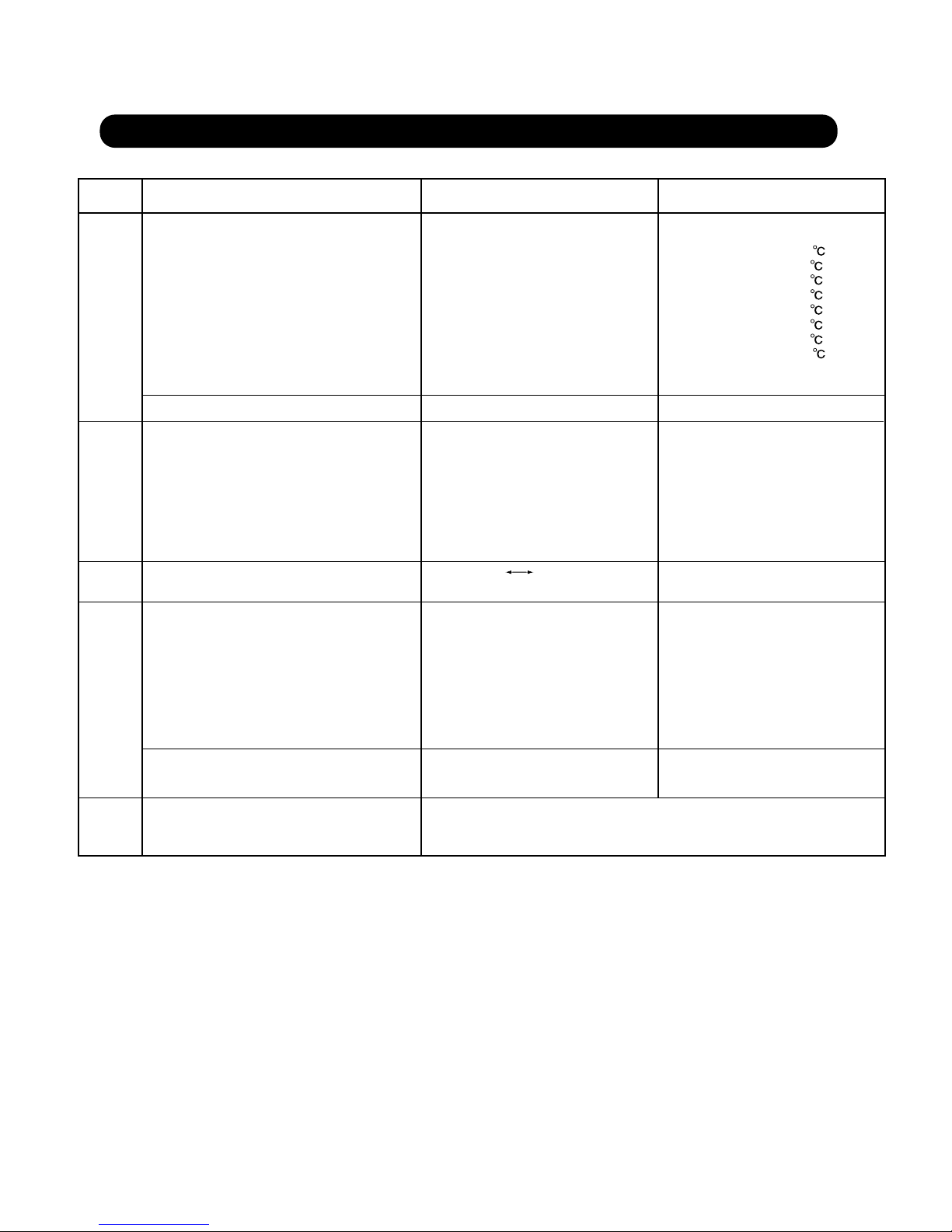
HPS: 2.7 MPa
LPS: 0.9 MPa
TH1: 81°C
TH4: 15°C
TH21: 27°C
TH22: 11°C
TH24: 13°C
Shall operate corresponding to the operation capacity of the indoor units.
Service tool used, output (CSV Excel)
Outdoor unit push button
SW operation
<On service tool>
High pressure
Low pressure
Discharge pipe temperature (outdoor unit)
Suction pipe temperature (outdoor unit)
Inlet air temperature (indoor unit)
Heat exchange inlet temperature (indoor unit)
Heat exchange outlet temperature (indoor unit)
Compressor operation
Data output
1-2-2 Check Items After Power ON
01-04
Function setting
Are the necessary functions set ?
< For the setting, Refer to the page 01-15 18 >
Outdoor unit Main
PCB push button
SW setting/check
[Note]
Cooling test run for each refrigerant circuit.
If multiple refrigerant circuits are test run at the same time, refrigerant circuit address setting errors cannot
be detected.
Judgement standard
Check
Check contentsProcedure
Power ON
Inlet air temperature and outlet air temperature difference shall be 10°C or
greater.
There shall be no abnormal sound or abnormal vibration.
There shall be no water leakage. There shall be no condensation on the drain,
cabinet, piping, and discharge port.
Shall operate according to the settings. (ON-OFF, set temperature change)
<Indoor unit service tool + actual measurement>
Outlet air temperature
Abnormal sound/abnormal vibration
Water leakage check
Remote controller operation
<Outdoor unit>
Outdoor Main PCB 7-seg. display
Operation voltage
Abnormal sound/
abnormal vibration
[Note] Turn on all indoor units power in the same refrigerant circuit address.
When the system operates with the indoor units remaining no power, it is cause of malfunction.
Indoor unit connection check
Are the number of connecting indoor units correct ?
Is the total capacity of indoor units correct ?
< For the checking, Refer to the page 01-08 >
Indoor unit
connection check
Address record
Address hold check
All the indoor units and outdoor units of the same refrigerant circuit can be
checked on the service tool.
Enter the set addresses in the check sheet.
Check whether or not the address setting is held by the service tool
after indoor/outdoor circuit breakers were turned OFF to ON.
[Note] Before connecting service tool, the address setting has to be completed.
〜
Fan operation
Louver operation (except duct)
Outlet air temperature
Abnormal sound/abnormal vibration
Water leakage check
Remote controller operation
Indoor unit
individual
operation
Shall be switched to all fan speeds in the cooling mode.
Louver shall be switched to all positions. Shall also swing.
Inlet air temperature and outlet air temperature difference shall be 10°C or
greater.
There shall be no abnormal sound or abnormal vibration.
There shall be no water leakage. There shall be no condensation on the drain,
cabinet, piping, and discharge port.
Shall operate according to the settings. (ON-OFF, set temperature change)
01-05
Judgement standard
Check
Check contentsProcedure
These are representative figures of AJYA54LALH at the standard condition. ( Indoor : 27
°C, Outdoor : 35°C )
If conditions are different from those above mentioned, the figures will be changed slightly.
It depends on following conditions.
Outdoor unit capacity
Indoor and outdoor temperature
Indoor unit capacity
Pipe length
etc
<Indoor unit service tool + actual measurement>
1. Error occured
- Check on the Error code on the Remote controller or Indoor unit or Outdoor unit or Service tool and
check the description of the Error code.
< Refer to the Trouble shooting in the Service manual.>
< Refer to the Execution of precautions 1-1 and Check item Before power ON 1-2-1>
2. No good performance without error code
- Check if the protection controlling is operating or not
Evaporator Icing up protection, High discharge temperature protection,etc.
< Refer to the part of protection controlling in the Service manual >
- Check on the refrigerant circuit
Refrigerant amount, Pipe blockage, Wrong position of separation pipes etc.
< Refer to the Execution of precautions 1-1 and Check item Before power ON 1-2-1>
< Refer to the regulation of installation in the Installation manual>
Trouble shooting on Test run operation
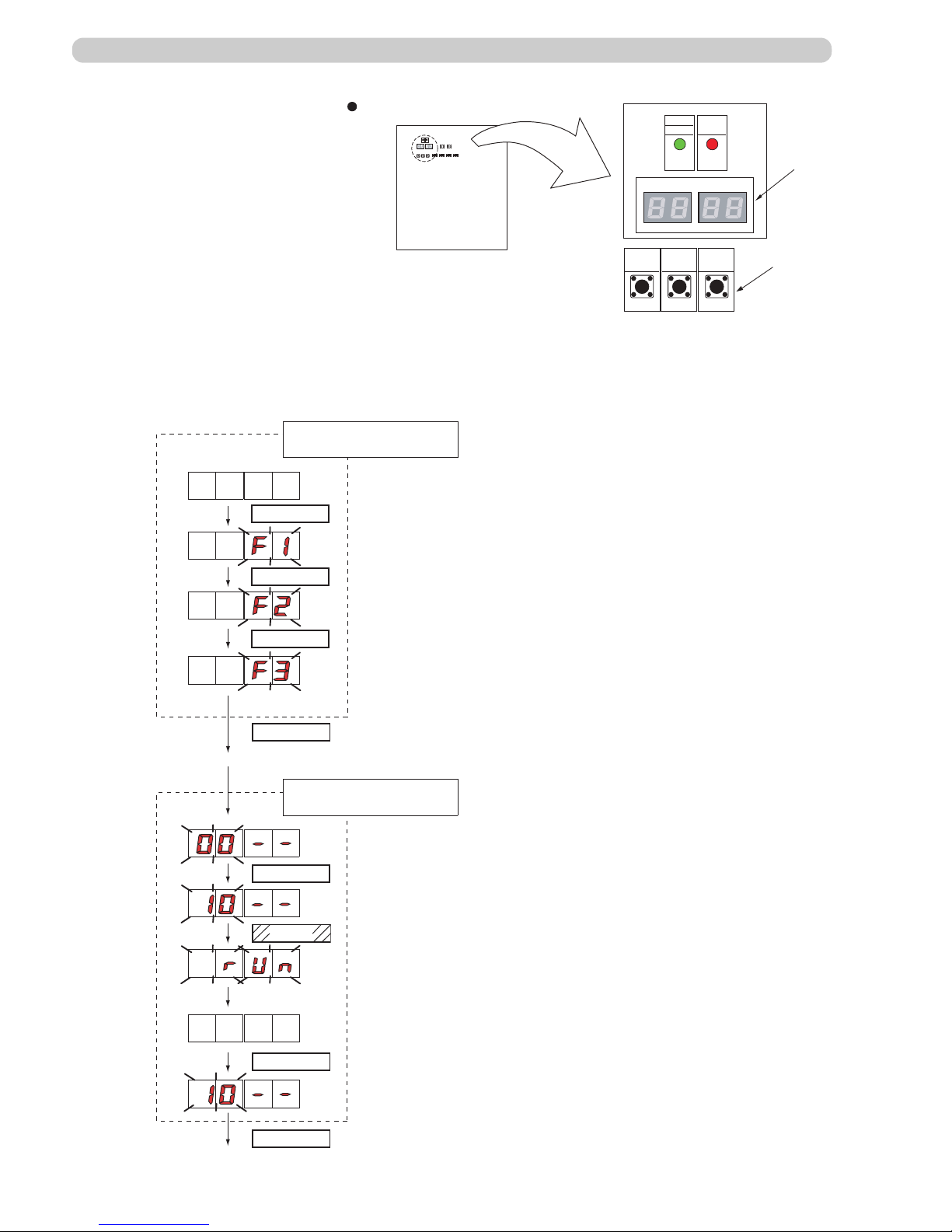
01-06
1-2-3 Automatic address setting for signal amplifiers When using signal amplifiers
When setting the address of the signal amplifier, please use the factory setting. (See the
installation manual of the signal amplifier)
When the system is normal, nothing will be displayed on the 7 segment display.
When ERROR is displayed, inspect the units.
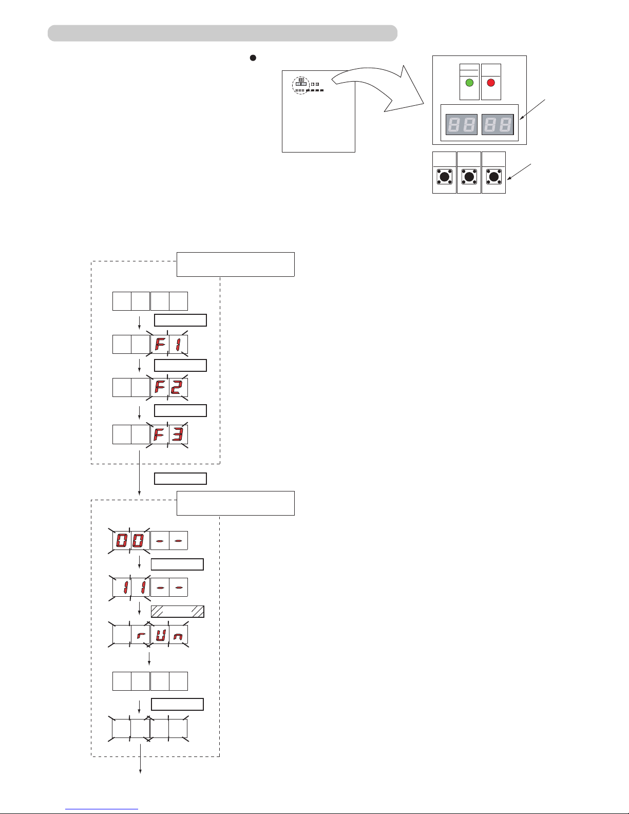
Use the “MODE/EXIT”, “SELECT”, and “ENTER” buttons on the outdoor unit Main PCB
to conÞ gure settings according to the procedures below.
1: FUNCTION Setting
First 2 digits Last 2 digits
(the display when the main power is turned on)
(When [F4] to [F9] are displayed, continue to press the "SELECT" button
until [ F3 ] is displayed)
MODE/EXIT
SELECT
SELECT
ENTER
SELECT
ENTER
Automatic address setting for
signal ampliÞ ers
Press the “SELECT” button until "10" is displayed
Press the “ENTER” button for more than 3 seconds
* Setting is complete when the number of unit is displayed
End
ENTER
MODE/EXIT
SWITCH POSITION
SW107 SW108 SW109
MODE
/EXIT
SELECT ENTER
LED101
(GREEN)
POWER
MODE
LED105 LED104
LED102
(RED)
ERROR
Push button switch
7 Segment
LED Lamp
Outdoor unit printed circuit board
*
01-07
SWITCH POSITION
SW107 SW108 SW109
MODE
/EXIT
SELECT ENTER
LED101
(GREEN)
POWER
MODE
LED105 LED104
LED102
(RED)
ERROR
Push button switch
7 Segment
LED Lamp
Outdoor unit printed circuit board
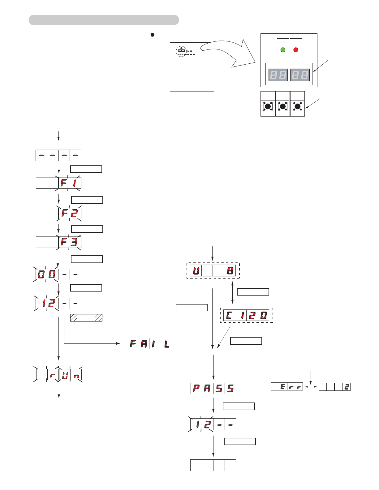
Check that the rotary switch IU AD on the indoor unit Main PCB is set to “00”.If it is not
set to “00”, it means the address of that device is not set. (Factory default is “00”).
Turn on the power of the indoor and outdoor units.
When the system is normal, nothing will be displayed on the 7 segment display.
When ERROR is displayed, inspect the units.
Use the “MODE/EXIT”, “SELECT”, and “ENTER” buttons on the outdoor unit Main PCB
to configure settings according to the procedures below .
1: FUNCTION Setting
First 2 digits Last 2 digits
(the display when the
main power is turned on)
(When [F4] to [F9] are displayed,
continue to press the “SELECT”
button until [F3] is displayed.)
MODE/EXIT
SELECT
SELECT
ENTER
1-2-4 Automatic address setting for Indoor units
It may take about 10 minutes for completing
the processing.
End
First 2 digits
Last 2 digits
Press the “SELECT” button until
“11” is displayed.
Press the “ENTER” button for more
than 3 seconds.
Automatic address setting
for indoor units
The number of indoor units with normal settings will be displayed at the first 2 digits of
the 7 segment display. The number of indoor
units with error will be displayed at the last 2
digits.
NOTE) After the “ENTER” button is pressed, the
end processing will occur for about 30 seconds.
During this period, the 7 segment will blink.
ENTER
SELECT
ENTER
Error
Found
01-08
SWITCH POSITION
SW107 SW108 SW109
MODE
/EXIT
SELECT ENTER
LED101
(GREEN)
POWER
MODE
LED105 LED104
LED102
(RED)
ERROR
Push button switch
7 Segment
LED Lamp
Outdoor unit printed circuit board
1-2-5 Indoor unit connection check
Please perform the indoor unit connection check according to following procedures.
MODE/EXIT
SELECT
SELECT
SELECT
ENTER
LED105
LED104
ENTER
Set to Function mode [F3].
(When [F4] to [F9] are displayed,
continue to press the “SELECT”
button until [F3] is displayed.)
Press the “SELECT” button until
“12” is displayed.
When indoor unit connection check
can not be performed
Turn on the power •
of indoor unit and
outdoor unit.
Press the •
“ENTER”
button for
more than 3 seconds.
This will be displayed when the •
Indoor unit connection check
starts.
MODE/EXIT
SELECT
ENTER
ENTER
ENTER
(*1)
(*2)
(*1) The number of connected
indoor units
(*2) Volume ratio of the indoor
units connection
Ex.) When 8 units are connected
Ex.) When the ratio is 120%
Please refer to the following “Error code”
for details
[ Note ] Error code
22.1: Connecting Indoor units capacity error
24.2: Connecting number of indoor unit error
26.1: Dual address number is existing
Other Error code: Refer to the Trouble shooting
When it finishes normally, nothing will be displayed on
7 segment display.
When error occurs
Confirm the number of connected indoor •
units and the volume ratio of the indoor
units connection.
Exit indoor unit connection check •
mode.
01-09
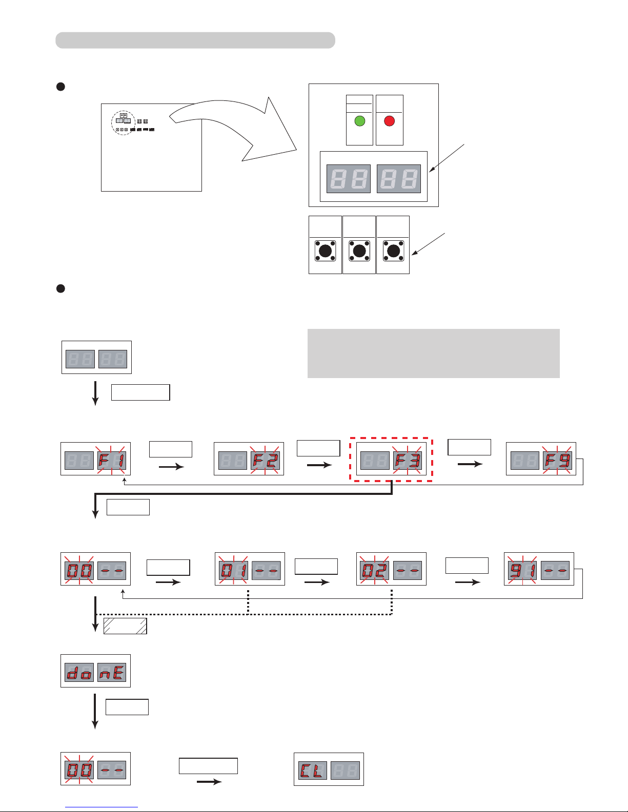
1-2-6 Test Run From Outdoor Main PCB
All the indoor units connected to the outdoor unit can be test-operated by push button setting.
LED105 LED104LED105 LED104 LED105 LED104LED105 LED104
L
ED
1
0
5
L
ED
1
0
4
LED105 LED104
LED105 LED104
[ Cooling test run ]
[ Heating test run ]
[ Test run stop ]
LED105 LED104
LED105 LED104
LED105 LED104
LED105 LED104
Press the ENTER button for at least 3 seconds.
Press the "ENTER" button or Time out ( 5 seconds)
MODE / EXIT
< Pursuance completion >
< Monitoring condition >
< Mode select condition >
< Return to mode select condition >
< Fuction select condition >
[ Function mode ]
SWITCH POSITION
SW107 SW108 SW109
MODE
/EXIT
SELECT ENTER
LED101
(GREEN)
POWER
MODE
LED105 LED104
LED102
(RED)
ERROR
Push button switch
7 Segment
LED Lamp
Outdoor unit printed circuit board
TEST RUN SETTING
[ Monitoring mode ] [ Setting mode ]
[ Error history mode ]
For a detailed description of push button operation, refer to the [D&T manual Chapter 6. SYSTEM DESIGN]
LED105 LED104
< Return to monitoring condition >
example, Normal indicate : [ Cooling mode ]
[ Central control setting
Forced reset ]
There are the following 2 methods of resetting test operation.
Automatic reset when 60 minutes has elapsed.(1)
Reset when operation stop was performed.(2)
Note
SELECT
SELECT
SELECT
SELECT
SELECT
SELECT
ENTER
ENTER
ENTER
MODE / EXIT
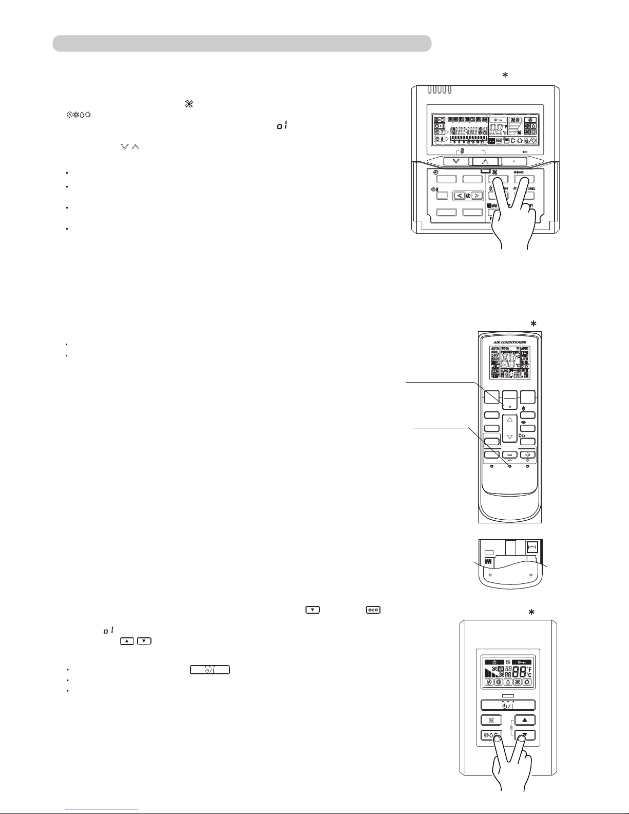
1-2-7 Test Run From Remote Controller
Press the TEST RUN button on the remote controller, while the air conditioner is running.
To end test run operation, press the remote controller START / STOP button.
When the air conditioner is being test run, the OPERATION
and TIMER lamps of indoor unit flash slowly at the same time.
START / STOP button
TEST RUN button
2. Standard wireless remote controller
Stop the indoor unit. Push the button and
button simultaneously for more than two seconds.
The air conditioner will start to conduct a test run and " " will display on
the remote controller display.
However, the , setting button does not have function,
but all other buttons, displays, and protection functions will operate.
To stop test run, push the START / STOP button of the standard wired remote
controller.
For the operation method, refer to the operating manual and perform operation
check.
Check that there are no abnormal sounds or vibration sounds during test run
operation.
Perform the test operation for 60 minutes.
1. Standard wired remote controller
UTY - LNH
UTY - RNK
button
button and
Stop the indoor and outdoor units. Push the remote controller
simultaneously for more than three seconds. The air conditioner will start to conduct a test
run and " " will display on the temperature display.
SET
However the setting button does not have function but all other buttons,
displays and protection functions will operate.
To stop test running press the button of the simple remote controller.
For the operation method refer to the operating manual and perform operation check.
Check that there are no abnormal sounds or vibration sounds during test run operation.
3. Simple remote controller
UTY - RSK
01-10
TIMER MODE
CLOCK
ADJUST
TEST
RUN
RESET
TIMER
SLEEP
FILTER RESET
SWING
SET
SET
ECONOMY
FANMODE
START
STOP
SET
TEMP.
TIMER MODE
DAY
SET BACK
CLOCK ADJUST
DAY OFF
TIMER DELETE TIMER SET
FAN MODE
SET TEMP.
START / STOP

6)
or
[ Select All (F2) ]: All of R.C.Group (Indoor units)
[ Identify Unit (F3) ] : Specific R.C.Group (Indoor unit)
Setup Menu
Indoor unit Special Setting
Test Operation
Central Controller
Setting
Indoor unit
Special setting
Indoor Unit
Set Temp. Range
Filter Sign
R.C. Prohibition
Group
Select
All
Identify
Unit
Clear
Unit
On
Select
All
Details
Off
Operation
Help
Setup
Menu
Monitor
Group
1
2
Monitor - All
UTY-DCG
On
Coll
25.0
℃
05/31 03:59
05/31 03:59
05/31 03:59
Test Operation
05/31 03:59
RCG_05
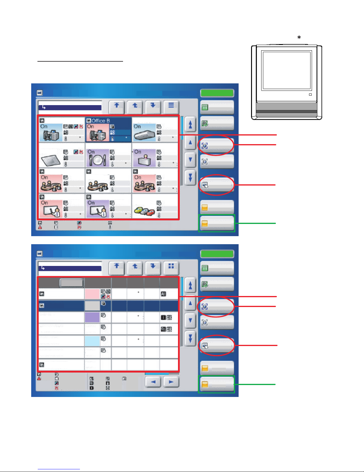
Test run operating procedure
<Monitor screen (icon)>
<Monitor screen (list)>
(1)
(1)
(2)
( * )
(1)
(1)
(2)
( * )
01-12
5. Touch panel controller
UTY - DTG
(1) Select the objective you want to test run.
Select the objective icon or list at the monitor screen. (Multiple selections is possible)
Select all the devices registered as objectives by pressing "Select All" on the monitor screen.
(2) After objective selection at (1), switch to the <Setting screen> by pressing "Operation".
On
C
1
On
On
On
On
On
On
On
On
Office B
Conference
A
Conference B
Meeting 1
Meeting
2
Parking lot
Meeting
3
Entrance
Restrant
Room
101
Office A
PC Room
Top Up
Down
List
Heat
Auto
Cool
26.0 C
24.0
C
Auto
22.0
C
Auto
24.0 C
21.5 C
Heat
21.5 C
21.5 C
Cool
Off
Off
Off
All
21.0
C
Heat
All
Lange Group
Lange Group
Top Up
Down
List
Office A
PC Room
Room 101
Restrant
Entrance
Meeting 1
Off
Off
Off
Mixed
Heat
Auto
Cool
24.0 C
26.0 C
Low
Auto
21.5 C
High
Office B
Mixed Mixed Mixed
Mixed
Name
Expand
Status Mode
Set
Temp
Fan
R/C
Prohibit
On
On
On
Status: On
Status: On
10/11.2008.Mar. 02:20 PM
10/11.2008.Mar. 02:20 PM
Monitor Mode
Monitor Mode
Heat
21.0
C
Off
On
Operation
Clear All
Select All
Schedule
Setting
Off
On
Operation
Clear All
Select All
Setting
Schedule
Group
Error
Schedule
Filter Sign
Op. Controlled
Op. Restricted
RC Prohibition
All
On/Off
On
Mode
Temp.
Timer
Filter
Mode
Set Temp.
Group
Error
Schedule
Filter Sign
Op.Controlled
Op.Restricted
<Setting screen>
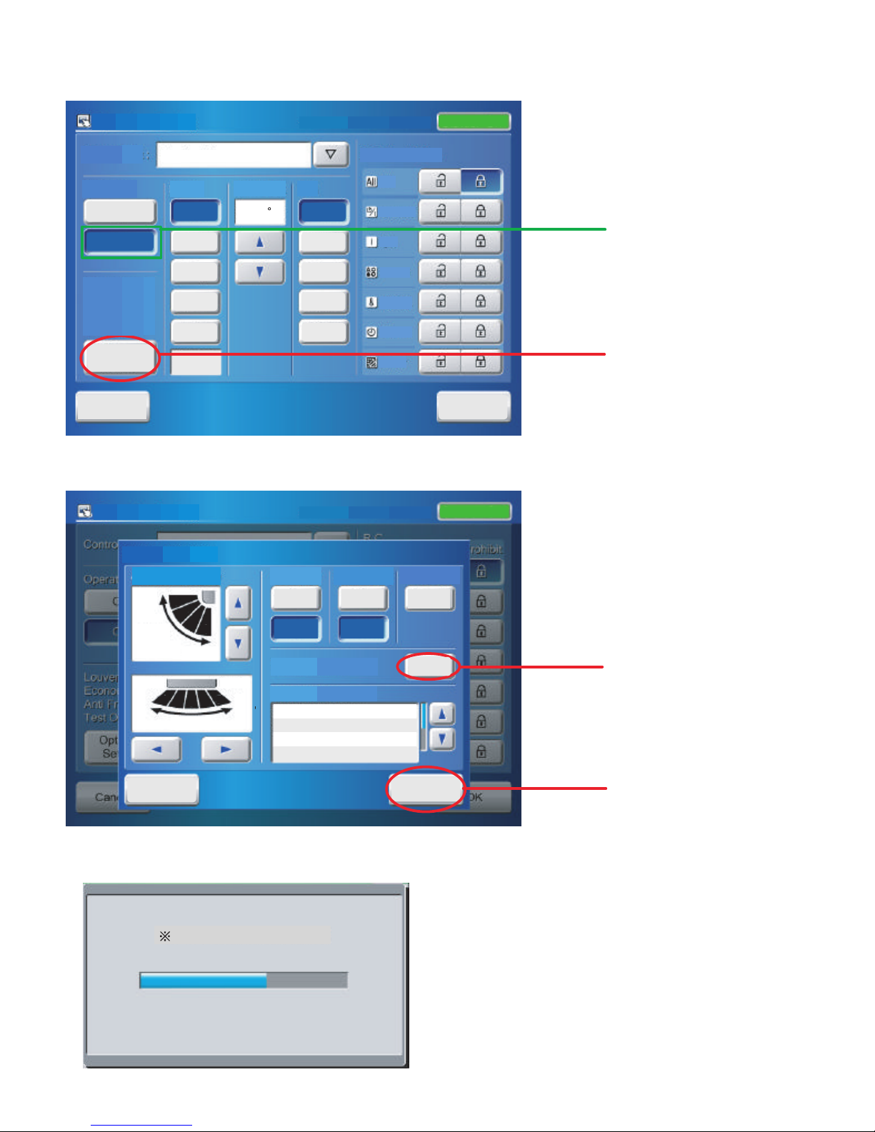
(3) Switch to the <Details setting screen> by pressing "Optional Setting" on the setting screen.
<Details setting screen>
(4) Send (start) test run by pressing "Start" and then pressing "OK" on the details setting screen. Test run continues for 60 minutes.
During sending, the slave screen shown below is displayed. When sending is completed, the sending slave screen and details setting
screen are closed.
To interrupt test run, select the device being test run and execute an
operation stop command.
(*) At the monitor screen, test run is reset by stopping operation
of the objective devices by pressing "OFF".
(*) Or test operation is reset by stopping operation of the objective
devices by pressing "Off" of Operation and then pressing "OK"
on the setting screen.
01-13
(3)
(4)
(5)
( * )
Cancel
Off
On
OK
Transferring data. Please wait.
On
On
Reset
Cancel
Stand by (Defrost)
Stand by (Oil Recovery)
Test Operation
Start
Air Flow Direction
Economy
Anti Freeze
Filter Sign
Operation
Test
Up
Down
Swing
Swing
Left Right
Off
Off
Special State
Status: On
1
2
3
4
5
1
2
3
4
SettingOptional
Cancel
OK
On
Off
Auto
Auto
Cool
Dry
Fan
Heat
Operation
Controlled
High
Med
Low
Quiet
Meeting Room
24.0 C
operation
R/C Prohibition
Mode Set Temp. Fan
Optional
Setting
All
On/Off
Filter
Timer
Temp.
Mode
On
10/11.2008.Mar. 02:20 PM
10/11.2008.Mar. 02:20 PM
Air Flow Direction
Economy
Anti Freeze
Filter Sign
Test Operation
Control Unit :
Operation Setting
Operation Setting
OK
Status: On
1-3 TEST RUN CONTROL
01-14
1. When the test run signal is transmitted from standard wired, wireless remote controller,
simple remote controller, transmitted network, and outdoor unit.
(1) The test run operation starts and the electric expansion valve is controlled to a maximum flow, regardless of
the temperature condition.
(2) Frost prevention operation has priority over item(1).
(3) Whether state of the indoor unit operates or stops, All units in the same refrigerant circuit will start to conduct a
test run in accordance with the operation mode set by push switch of outdoor unit ( see 1 - 2 - 3 ).
(4) After 60 minutes passes, the test run stops.
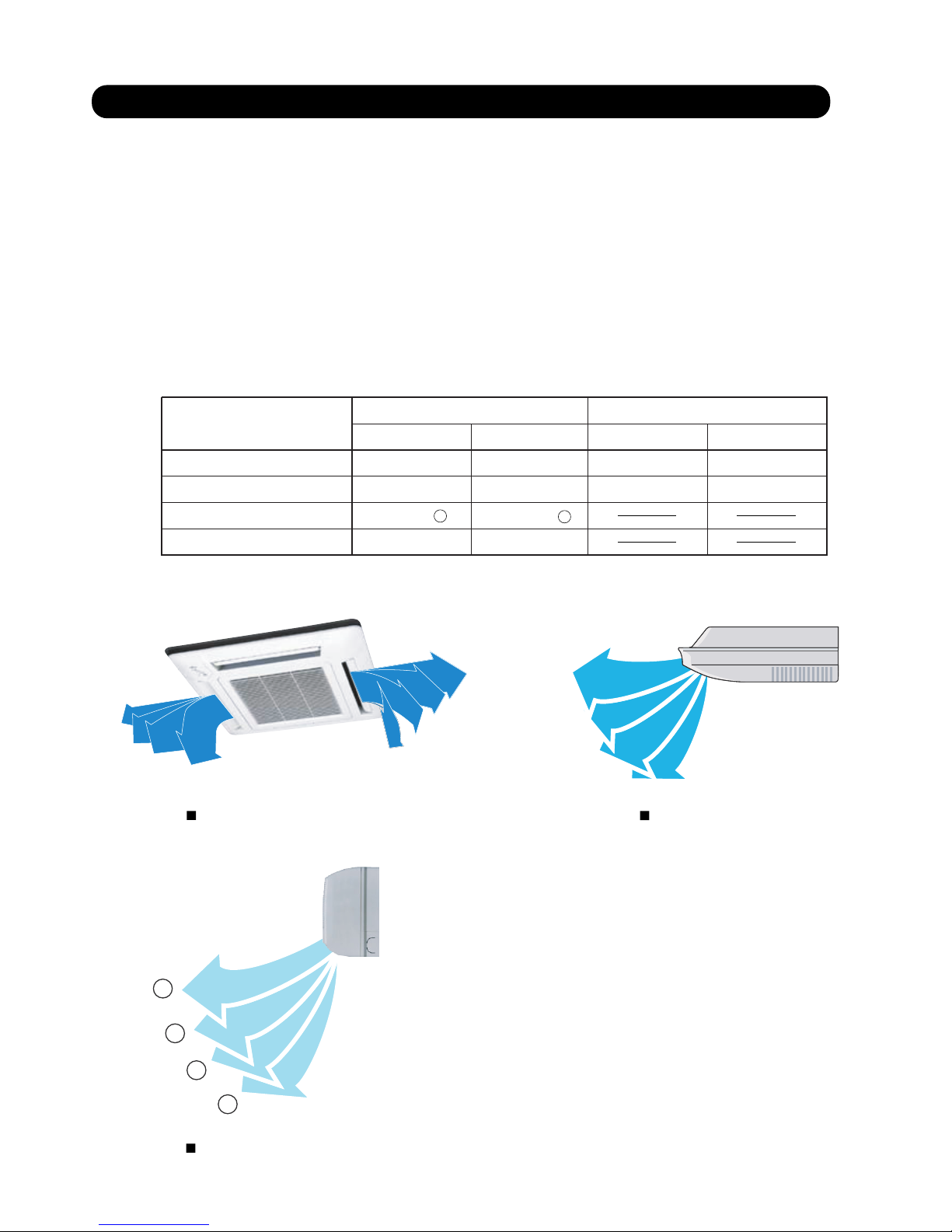
(5) Test running initialization is shown below.
Fan speed Hi Hi
Room Temperature Indication 18 30
Hi Hi
18 30
Vertical Air Direction Panel
Swing
Operating Mode
Cooling Heating Cooling Heating
OFF OFF
Position
1
Position
4
EXCEPT FOR THE DUCT MODEL DUCT TYPE
CEILING TYPE
COMPACT CASSETTE TYPE
COMPACT WALL MOUNTED TYPE
4
3
2
1
1
2
3
4
*EXAMPLE
1
2
3
4
4
3
2
1
Push switch onoutdoor
unit PCB
00 Connected number of indoor unit The number of the communicating unit is displayed
01
Software version :
[ ] [ ] [ ] [ ] [ ] displays by five items
It skips when there is no suffix
02 Software version of INV PCB
03 Software version of communication PCB
Operation of
each part
10 Rotational speed of outdoor unit fan motor The rotational speed of the outdoor unit fan motor is displayed
[ rpm ]
11 Rotational speed of INV compressor The rotational speed of the compressor is displayed
[ rps ]
12 Current value of INV compressor Current value of INV compressor is displayed
[ A ]
14 Pulse of EEV1 Pulse of EEV1 is displayed
[ pls ]
15
Pulse of EEV2 Pulse of EEV2 is displayed
[ pls ]
Time guard 20 Accumulated current time Accumulated current time is displayed
[ 10 hour ]
21 INV compressor accumulated time
[ Cooling ]
Accumulated time is displayed in the cooling operation of the
INV compressor
[ 10 hour ]
22 INV compressor accumulated time
[ Heating ]
Accumulated time is displayed in the heating operation of the
INV compressor
[ 10 hour ]
Refrigerant
cycle data 1
30 Information on Thermistor 1
( INV compressor discharge temperature )
The value of the Thermistor 1 is displayed
32
Information on Thermistor 3
( Outdoor temperature )
The value of the Thermistor 3 is displayed
33 Information on Thermistor 4
( Suction temperature )
The value of the Thermistor 4 is displayed
34
Information on Thermistor 5
( Heat-exchanger temperature )
The value of the Thermistor 5 is displayed
36
Information on Thermistor 7
( Liquid temperature 2 )
The value of the Thermistor 7 is displayed
37
Information on Thermistor 8
( Sub-cool heat-exchanger inlet temperature )
The value of the Thermistor 8 is displayed
38 Information on Thermistor 9
( Sub-cool heat-exchanger outlet temperature )
The value of the Thermistor 9 is displayed
39 Information on Thermistor 10
( INV compressor temperature )
The value of the Thermistor 10 is displayed
50
Information on pressure sensor 1
( High pressure sensor )
The value of the pressure sensor 1 is displayed
[ MPa ] or [ psi ]
51
Information on pressure sensor 2
( Low pressure sensor )
The value of the pressure sensor 2 is displayed
[ F1 ]
Monitor mode
Setting Mode
ITEM
CODE No.
Information contents
Refrigerant
cycle data 2
Device and
system
Software version of outdoor unit
Classification
01-15
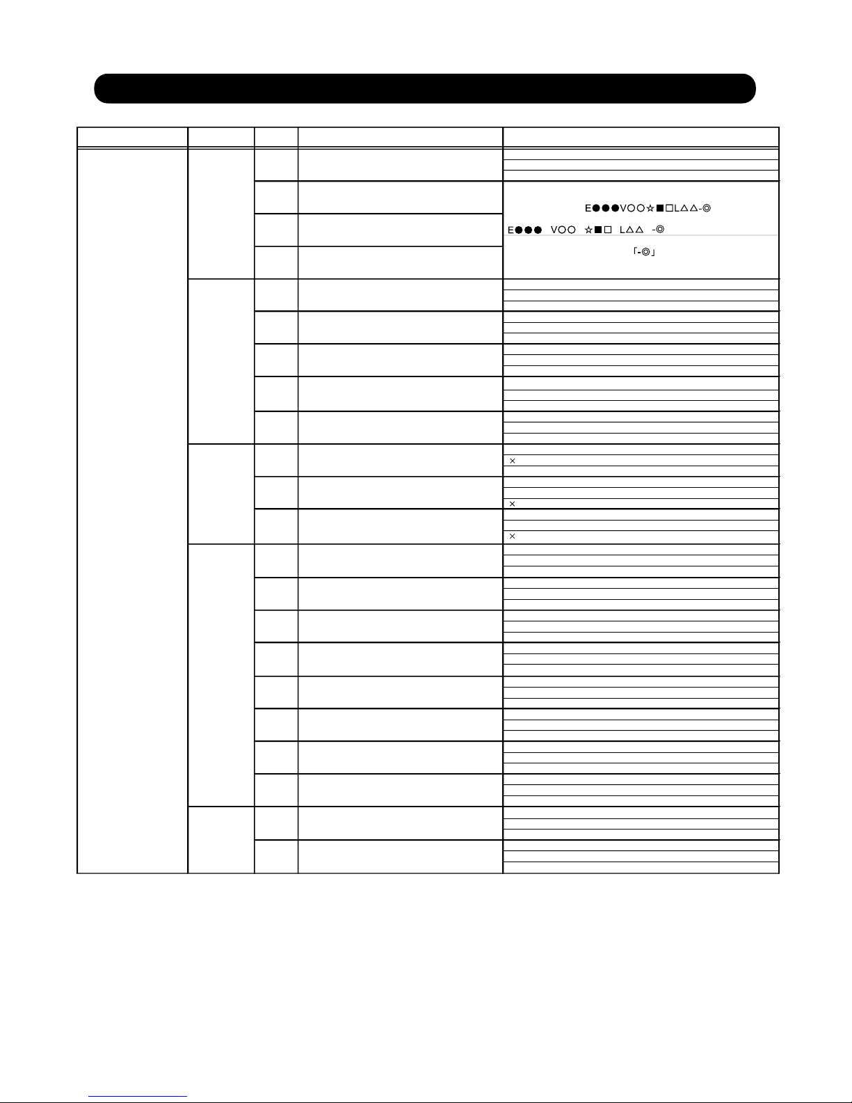
1-4 Field Setting And Monitor Mode List for Outdoor unit
[ MPa ] or [ psi ]
[°C ] or [°F ]
[°C ] or [°F ]
[°C ] or [°F ]
[°C ] or [°F ]
[°C ] or [°F ]
[°C ] or [°F ]
[°C ] or [°F ]
[°C ] or [°F ]
Setting Mode
ITEM
CODE No.
Setting Function
Default
Install 00 Pipe length setting 00 40-65m
Setting mode
01 0-40m
02 65-90m
03 90-120m
04
Correction 10
Sequential start shift
00
01
02
03
11
Cooling capacity shift 00 Normal mode
01 Save energy mode 1 (+2°C)
02 High power mode 1 (-2°C)
03 High power mode 2 (-4°C)
12
Heating capacity shift
00 Normal mode
01 Save energy mode (-2°C)
02 High power mode 1 (+2°C)
03 High power mode 2 (+4°C)
13 Defrost setting shift 00 End temperature:Normal
01 End temperature:Higher
01 Emergency stop
21 Operation mode selecting method 00 Priority given to the first command
01 Priority given to the external input of outdoor unit
02 Priority given to the master indoor unit
22
Snow falling protection fan mode
00 Normal operation
01
23
Interval setting for snow falling
00 Standard
01
02
03
24
High static pressure mode
00 Standard
01
02
28 Change of unit (Temperature) 00 Celsius(°C)
01 Fahrenheit ( F)
29 Change of unit (Pressure) 00 MPa
01 psi
Change of
Change of
function 3
30 Energy saving level setting 00 Level 1 (stop)
01 Level 2 (operated at 40% capacity)
02 Level 3 (operated at 60% capacity)
03 Level 4 (operated at 80% capacity)
04 Level 5 (operated at 100% capacity)
Low noise 40 Capacity priority setting 00 Off (quiet priority)
01 On (capacity priority)
41 Low noise mode setting
00 Off (Normal)
60
Back up operation
00 Standard
01
01 On (Low noise mode operation is always done)
42
Low noise mode operation level
00 Standard (47dB)
01
[ F2 ]
ITEM
CODE No.
Standard
20 Switching between forced stop or 00 Forced stop
Change of
function 1
emergency stop
protection fan mode
setting 1
(in low noise mode)
function 2
Classification
01-16
Push switch
on outdoor unit PCB
Setting is forbidden
Setting is forbidden
Setting is forbidden
Setting is forbidden
70
Electricity meter No. setting 1
(Set the ones digit and tens digit of the No of
the electricity meter connected to CN135.)
*3
00~99 Setting number x00~x99
00
71
Electricity meter No. setting 2
(Set the hundreds digit of the No. of the
electricity meter connected to CN135.)
*3
00~02 Setting number 0xx~2xx 00
72
Electricity meter pulse setting 1
(Set the ones digit and tens digit of the No. of
the electricity meter pulse setting connected
to CN135.)
*4
00~99 Setting number xx00~xx99 00
73
Electricity meter pulse setting 2
(Set the hundreds digit and thousands digit
of the electricity meter pulse setting connected
to CN135.)
*4
00~99 Setting number 00xx~99xx 00
Change of
function 4
*3 : When electricity meter No. is set to "000" and "201 to 299", the pulses input to CN135 become ineffective.
Available setting number is "001" to "200"
*4 : When the electricity meter pulse setting is set to "0000", the pulses input to CN135 become ineffective.
Available setting number is "0001" to "9999"
( Refer to Design & Technical Manual for details.)
( Refer to Design & Technical Manual for details.)
( Refer to Design & Technical Manual for details.)
( Refer to Design & Technical Manual for details.)
Setting is forbidden: Any of problems caused by changing these setting is not covered by the warranty.
14 Pressure equalization time shift
before defrosting start
00 No time shift
01 Shift 1 ( 30 sec.)
02 Shift 2 ( 60 sec.)
03
04
Shift 3 ( 90 sec.)
Shift 3 ( 120 sec.)
Only for solution :
Only when the refrigerant noise during Defrosting was pointed out. It is the case that the
compressor operating time in heating will be shorter.
Only for solution
04 High power mode 3 (-5°C)
03
Oil recovery
00
02
Setting is forbidden
01
25
Oil recovery Abnormal
low pressure protection control
00
01
26
27 Error code Notification
00
01
Enable
Disable
31
Heating Starting prosess
00
01
Standard
Standard
Standard
Setting is forbidden
Setting is forbidden
Setting is forbidden
Setting is forbidden
Setting is forbidden
Push switch on
outdoor unit PCB
Forced operation 00 Cooling test run
Forced thermostat-ON in Cooling.
Function mode
01 Heating test run Forced thermostat-ON in Heating.
02 Test run stop Test run is stopped.
Install and
maintenance 1
10 Signal amplifier automatic address Automatic address setting operates for signal amplifier.
11 Indoor unit automatic address
21 Vacuuming mode Vacuuming mode operatesRefer to page 01-01 for the function.
Clear 30 Error history clear All the abnormal code histories are cleared.
32 Current time clear Accumulated current time becomes [ 0 ]
33 INV compressor accumulated time clear Accumulated time of the INV compressor becomes [ 0 ]
35 Field setting all clear Return to default the all set items.
Reset 40 Abnormal reset It was displayed when abnormality occurs, and abnormal
code is reset.
This is a function that uses to clear abnormal display after the
repair is completed.
Please operate the switch after power off or power on
the outdoor unit.
Specialtyfunction 91 Foreced Central control function release
Maximum memorized indoor unit number is reset.
Setting Mode
ITEM
CODE No.
Setting Function
Install and
maintenance 2
*
Automatic address setting operates for indoor unit of same
refrigerant circuit.
[ F3 ]
01-17
Compressor Motor Loss of Synchronization
Compressor 1 Temperature Abnormal
Inverter Compressor Start Up Error
Discharge Temperature 1 Abnormal
Low Pressure Abnormal
Current Sensor 1 Error
Trip Detection
Rush Current Limiting Resistor Temp Rise Protection
Outdoor Unit FAN motor 1 Lock Error
Outdoor Unit FAN motor 2 Lock Error
< Reset Error Item List By Abnormal Reset Setting >
*
Push switch on
outdoor unit PCB
1 time ago (Newest)
Error History Mode
2 times ago
5 times ago
Meaning of Error History Number
ITEM
CODE No.
Information contents
[ F9 ]
00
01
02
03
04
05
06
07
08
09
Error history
10 times ago (Oldest)
4 times ago
3 times ago
6 times ago
7 times ago
8 times ago
9 times ago
When the centralized control device failure, and the centralized
control setting cannot be released, this function is used.
All the limitations set with the centralized control device are
released.
Maximum memorized indoor unit number reset
41
"E14.5:Indoor unit number shortage" error is cleared.
When the error occurred, the error code is memorized up to
10 on Main PCB.
If the memorized error code becomes over 10, the oldest one
will be erased.
Refer to Chapter 4.TROUBLE SHOOTING
4-2-3 Error Code List of Outdoor unit
12
The number of indoor units and the total capacity of indoor units
of same refrigerant circuit.
Indoor unit connection check
36
Clear memorized information of "F3 - 12 "
( Indoor unit connection check )
The information of the number of indoor units and the total
capacity of indoor units are cleared.
34 Constant Speed compressor accumulated
time clear
Not in Use on J-Series
90
Foreced Normal operation release Normal operation foreced release
01-18
1-5 Field Setting / Function Setting for Indoor unit
Setting Mode
ITEM
CODE No.
Setting Function
Default
Indoor unit field setting
Address
setting by
remote controller
01 Indoor unit address 00~63 00~63 00
02 Refrigerant circuit address 00~99 00~99 00
Filter 11 Filter indicator Interval 00 Default
01
Longer
02 Shorter
13 Filter sign display 00 Enable
01 Disable
02 Display only on central remote control
Airflow 20 Ceiling airflow 00 Default
(Cassette type only) 01 High ceiling
23 Vertical airflow direction 00 Default
01 Raise
24 Horizontal swing airflow direction 00 Default
01 Left half
02 Right half
Correction
30
Cool air temperature trigger
00 Default (0°C)
01 Temperature overshoot setting (+2
°C)
02 Temperature undershoot setting (-2
°C)
31 Heat air temperature trigger 00 Default (0°C)
01 Temperature undershoot setting (-6
°C)
02 Temperature slightly undershoot setting (-4
°C)
03 Temperature overshoot setting (+4
°C)
Change of 40 Auto restart 00 Enable
01 Disable
43 Cool air prevention 00 Enable
01 Disable (Ventilation mode)
46 External control 00 Start / Stop
01 Emergency stop
47 Error report target 00 All
01 Display only for central remote control
ITEM
CODE No.
Function 1
Classification
26
32
Model name Range of static pressure
AR XD 07L ATH
0 to 90 Pa
AR XD 09 LATH
AR XD 12LATH
AR XD 14LATH
AR XD 18L ATH
AR XD 24L ATH 0 to 50 Pa
00
01
02
03
04
05
06
07
08
09
31
0 Pa
10 Pa
20 Pa
30 Pa
40 Pa
50 Pa
60 Pa
70 Pa
80 Pa
90 Pa
25 Pa
Static Pressure setting
- Slim Duct Only -
The Range of static pressure is
different from one model to other.
Temperature correction in Auto
00
01
Disable
Enable (Nonfunctional on J2 Series)
2. OUTDOOR UNIT OPERATION CONTROL

2-1 INPUT / OUTPUT LIST
2. OUTDOOR UNIT
02-01
Input / output or kind of detail Control range
Discharge pressure sensor <HIGH> Pressure sensor Measure range 0.0 to 5.0MPa
Suction pressure sensor <LOW> Pressure sensor Measure range 0.0 to 1.7MPa
Discharge temperature sensor <TH1> Themistor <Blue>
Measure range 10 to 130
Heat exchanger temperature sensor <TH5> Themistor <Pink>
Measure range -35 to 70
Sub-cool heat exchanger (inlet) sensor <TH8> Themistor <White>
Measure range -35 to 70
Sub-cool heat exchanger (outlet) sensor<TH9> Themistor <Brown>
Measure range -35 to 70
Liquid temperature sensor <TH7> Themistor <Green>
Measure range -35 to 70
Suction temperature sensor <TH4> Themistor <Red>
Measure range -35 to 70
Outdoor temperature sensor <TH3> Themistor < - >
Measure range -25 to 58
Operation current sensor
Current transformer
Rotary SW & DIP-SW & Push SW
Electronic expansion valve 1 (Main) EEV coil Operating voltage DC12V
Electronic expansion valve 2 (SC-Hex) EEV coil Operating voltage DC12V
4-way valve 4-way valve coil AC220-240V, 50/60Hz 6/5 W
Solenoid valve Comp pressure equalizing valve AC220-240V, 50Hz, 6W
Crank case heater For Inverter Compressor AC240V, 25W
Base heater Field supply AC220-240V, 35W
LON WORKS
Inverter communication
External input 1 (CN131)
(Low noise mode operation)
External input 2 (CN132)
(Cooling / Heating priority)
External input 3 (CN133)
(Outdoor unit operation peak control)
External input 4 (CN134)
(Emergency stop operation)
Dry contact input
Single LED 101
Single LED 102
LED display
Address and function setting
Display the information on operation, error and setting with single LED and
7 segment LED.
Control output: DC 0/12-24V, Max.30mA
Control output: DC 0/12-24V, Max.30mA
External output 1 (CN136) (Error display)
External output 2 (CN137) (Operation display)
ON (Error) / OFF (Normal)
ON (Operation) / OFF (Stop)
Communication
Input / Output
External
Input / Output
I
N
P
U
T
O
U
T
P
U
T
Compressor temperature sensor <TH10> Themistor < - > Measure range 10 to 130
Pressure switch
Pressure switch
Open 4.2MPa Short 3.2MPa
Fan motor 1 (Upper) DC Brushless motor
7 Segment LED
Compressor
Magnetic relay
Operation coil AC220-240V, 50Hz
Indoor unit Outdoor unit
Fan motor 2 (Lower) DC Brushless motor
2-2-1 Operation / Stop Condition
When cooling requirement capacity or heating requirement capacity from either of the indoor units in the same
refrigerant circuit is input, the compressor operates.
When all the indoor units in no "cooling requirement capacity" or "heating requirement capacity",
the compressor
is stopped.
But in the following case, the compressor operates in accordance with operation of each mode.
During 3 minute restart prevention operation
Icing protection
Failure (Refer to chapter 4, TROUBLE SHOOTING )
Under expansion valve initialization
At protective operation
Emergency stop
Defrost operation
02-02
2-2 COMPRESSOR OPERATION
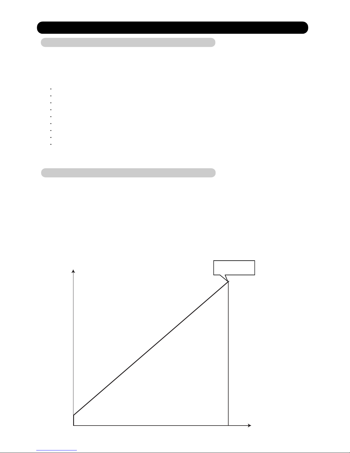
2-2-2 Capacity Control
(1) Capacity of compressor operation
By the operation of DC inverter rotary compressor, the amount of required refrigerant circulation acceding to
cooling and heating load can be supplied from compressor efficiently.
DC inverter rotary compressor is able to control the amount of
required refrigerant circulation in details.
Cooling/Heating load
Capacity of
compressor operation
Total capacity
Peak cut stop operation
Oil recovery
Inverter Compressor
 Loading...