

AirStage ASYA09GACH, ASYA07GACH, ASHA09GACH, ASYA12GACH, ASHA12GACH Installation Manual
...
TM
INSTALLATION MANUAL
INDOOR UNIT (Wall Mounted Type: EEV internal)
For authorized service personnel only.
INSTALLATIONSANLEITUNG
INNENGERÄT (wandmontierter Typ: EEV intern)
Nur für autorisiertes Fachpersonal.
EnglishDeutschFrançaisEspañolItalianoΕλληνικάPortuguêsРусскийTürkçe
ASYA04GACH/ASHA04GACH
ASYA07GACH/ASHA07GACH
ASYA09GACH/ASHA09GACH
ASYA12GACH/ASHA12GACH
ASYA14GACH/ASHA14GACH
MANUEL D’INSTALLATION
APPAREIL INTÉRIEUR (Type montage mural : interne EEV)
Pour le personnel agréé uniquement.
MANUAL DE INSTALACIÓN
UNIDAD INTERIOR (Tipo montado en pared: EEV interna)
Únicamente para personal de servicio autorizado.
MANUALE DI INSTALLAZIONE
UNITÀ INTERNA (tipo montato a parete: EEV interno)
A uso esclusivo del personale tecnico autorizzato.
ΕΓΧΕΙΡΙΔΙΟ ΕΓΚΑΤΑΣΤΑΣΗΣ
ΕΣΩΤΕΡΙΚΗ ΜΟΝΑΔΑ (Επιτοίχιος Τύπος: ΗΕΒ εσωτερικά)
Μόνο για εξουσιοδοτημένο τεχνικό προσωπικό.
MANUAL DE INSTALAÇÃO
UNIDADE INTERIOR (Tipo mural: modelo interno com EEV)
Apenas para técnicos autorizados.
РУКОВОДСТВО ПО УСТАНОВКЕ
ВНУТРЕННИЙ МОДУЛЬ (настенного типа: внутренний электронный расширительный клапан)
Только для авторизованного обслуживающего персонала.
MONTAJ KILAVUZU
İÇ ÜNİTE (Duvara Monteli Tip: EEV dahili)
Yalnızca yetkili servis personeli için.
PART NO. 9373370192
INSTALLATION MANUAL
PART NO. 9373370192
VRF system indoor unit (Wall mounted type: EEV internal)
CONTENTS
1. SAFETY PRECAUTIONS ............................................................................................ 1
2. ABOUT THE UNIT ....................................................................................................... 1
2.1. Precautions for using the R410A refrigerant ......................................................... 1
2.2. Special tool for R410A .......................................................................................... 1
2.3. Accessories .......................................................................................................... 2
2.4. Optional parts .......................................................................................................2
3. INSTALLATION WORK ............................................................................................... 2
3.1. Selecting an installation location .......................................................................... 2
3.2. Installation dimensions .........................................................................................2
3.3. Installing the unit ................................................................................................... 3
PIPE INSTALLATION .................................................................................................. 4
4.
4.1. Selecting the pipe material ...................................................................................4
4.2. Pipe requirement ..................................................................................................4
4.3. Flare connection (pipe connection) ...................................................................... 5
5. ELECTRICAL WIRING ................................................................................................6
5.1. Electrical requirement ........................................................................................... 6
5.2. Wiring method ...................................................................................................... 6
5.3. Unit wiring ............................................................................................................. 7
6. FIELD SETTING .......................................................................................................... 8
6.1. Setting the address ............................................................................................... 8
6.2. Custom code setting ............................................................................................. 9
6.3. Switching the upper limit of cooling temperature .................................................. 9
6.4. Function Setting .................................................................................................... 9
6.5. Connecting the wired remote controller (If necessary) ....................................... 10
6.6. External input and external output (Optional parts) ............................................ 11
6.7. Installing the control unit ..................................................................................... 12
7. FINISHING................................................................................................................. 13
8. TEST RUN ................................................................................................................. 14
8.1. Test run using Outdoor unit (PCB) ...................................................................... 14
8.2. Test run using Remote Controller .......................................................................14
9. CHECK LIST ..............................................................................................................14
10. ERROR CODES ........................................................................................................ 14
1. SAFETY PRECAUTIONS
Be sure to read this Manual thoroughly before installation.
The warnings and precautions indicated in this Manual contain important information
pertaining to your safety. Be sure to observe them.
Hand this Manual, together with the Operating Manual to the customer.
Request the customer to keep them on hand for future use, such as for relocating or
repairing the unit.
WARNING
Request your dealer or a professional installer to install the unit in accordance with this
Manual.
An improperly installed unit can cause serious accidents such as water leakage,
electric shock, or fi re.
If the unit is installed in disregard of the instructions in the Installation Manual, it will void
the manufacturer’s warranty.
Do not turn ON the power until all work has been completed.
Turning ON the power before the work is completed can cause serious accidents such
as electric shock or fi re.
If refrigerant leaks while work is being carried out, ventilate the area.
If the refrigerant comes in contact with a fl ame, it produces a toxic gas.
Installation work must be performed in accordance with national wiring standards by
authorized personnel only.
Except for EMERGENCY, never turn off main as well as sub breaker of the indoor
units during operation. It will cause compressor failure as well as water leakage.
First, stop the indoor unit by operating the control unit, converter or external input
device and then cut the breaker.
Make sure to operate through the control unit, converter or external input device.
When the breaker is designed, locate it at a place where the users cannot start and
stop in the daily work.
This mark indicates procedures which, if improperly performed,
might lead to the death or serious injury of the user.
This mark indicates procedures which, if improperly performed,
CAUTION
Read carefully all security information before use or install the air conditioner.
Do not attempt to install the air conditioner or a part of the air conditioner by yourself.
This unit must be installed by qualified personnel with a c apacity certificate for
handling refrigerant fluids. Refer to regulation and laws in use on installation place.
The installation must be carried out in compliance with regulations in force in the place of
installation and the installation instructions of the manufacturer.
This unit is part of a set constituting an air conditioner. It must not be installed alone or
with non-authorized by the manufacturer.
Always use a separate power supply line protected by a circuit breaker operating on all
wires with a distance between contact of 3mm for this unit.
The unit must be correctly earthed (grounded) and the supply line must be equipped
with a dif ferential breaker in order to protect the persons.
The units are not explosion proof and therefore should not be installed in explosive
atmosphere.
Never touch electrical components immediately after the power supply has been
turned off. Electric shock may occur. After turning off the power, always wait 5 minutes
before touching electrical components.
This unit contains no user-serviceable parts. Always consult authorized service
personnel to repairs.
When moving, consult authorized service personnel for disconnection and installation
of the unit.
might possibly result in personal harm to the user, or damage to
property.
2. ABOUT THE UNIT
2.1. Precautions for using the R410A refrigerant
1
Do not introduce any substance other than the prescribed refrigerant into the
refrigeration cycle.
If air enters the refrigeration cycle, the pressure in the refrigeration cycle will become
abnormally high and cause the piping to rupture.
If there is a refrigerant leakage, make sure that it does not exceed the concentration
limit.
If a refrigerant leakage exceeds the concentration limit, it can lead to accidents such
as oxygen starvation.
Do not touch refrigerant that has leaked from the refrigerant pipe connections or other
area. Touching the refrigerant directly can cause frostbite.
If a refrigerant leakage occurs during operation, immediately vacate the premises and
thoroughly ventilate the area.
If the refrigerant comes in contact with a fl ame, it produces a toxic gas.
2.2. Special tool for R410A
To install a unit that uses the R410A refrigerant, use dedicated tools and piping
materials that have been manufactured specifi cally for R410A use.
Because the pressure of the R410A refrigerant is approximately 1.6 times higher than
the R22, failure to use dedicated piping material or improper installation can cause
rupture or injury.
Furthermore, it can cause serious accidents such as water leakage, electric shock, or
fi re.
Tool name Contents of change
Pressure is huge and cannot be measured with a
conventional (R22) gauge. To prevent erroneous mixing
of other refrigerants, the diameter of each port has been
Gauge manifold
Charging hose
Vacuum pump
Gas leakage detector Special gas leakage detector for HFC refrigerant R410A.
changed.
It is recommended to use a gauge manifold with a high
pressure display range –0.1 to 5.3 MPa and a low pressure
display range –0.1 to 3.8 MPa.
To increase pressure resistance, the hose material and base
size were changed.
A c
a vacuum pump adapter.
Be sure that the pump oil does not backflow into the system.
Use one capable for vacuum
–755 mmHg).
WARNING
WARNING
onventional (R22) vacuum pump can be used by installing
suction of –100.7 kPa (5 Torr,
En-1
2.3. Accessories
WARNING
For installation purposes, be sure to use the parts supplied by the manufacturer or
other prescribed parts.
The use of non-prescribed parts can cause serious accidents such as the unit to fall,
water leakage, electric shock, or fi re.
The following installation parts are furnished. Use them as required.
Keep the Installation Manual in a safe place and do not discard any other accessories
until the installation work has been completed.
Do not discard any accessories needed for installation until the installation work has been
completed.
Name and Shape Q’ty Application
Operating Manual
1
Installation Manual
Wall hook bracket
Cable tie
Cloth tape
Tapping screw (M4×25mm)
Connecting cable
Air cleaning filter
Air cleaning filter frame
(This book)
1
For indoor unit installation
1
For remote controller cable binding
1
For indoor unit installation
1
For wall hook bracket installation
8
For wired remote controller installation
1
For installation, refer to the
“CLEANING AND CARE” in the
operating manual.
2
2
3. INSTALLATION WORK
Correct initial installation location is important because it is diffi cult to move unit after it is
installed.
3.1. Selecting an installation location
WARNING
Select installation locations that can properly support the weight of the indoor. Install
the units securely so that they do not topple or fall.
CAUTION
Do not install the unit in the following areas:
• Area with high salt content, such as at the seaside.
It will deteriorate metal parts, causing the parts to fail or the unit to leak water.
• Area fi lled with mineral oil or containing a large amount of splashed oil or steam,
such as a kitchen.
It will deteriorate plastic parts, causing the parts to fail or the unit to leak water.
• Area that generates substances that adversely affect the equipment, such as sulfuric
gas, chlorine gas, acid, or alkali.
It will cause the copper pipes and brazed joints to corrode, which can cause
refrigerant leakage.
• Area that can cause combustible gas to leak, contains suspended carbon fi bers or
fl ammable dust, or volatile infl ammables such as paint thinner or gasoline.
If gas leaks and settles around the unit, it can cause a fi re.
• Area where animals may urinate on the unit or ammonia may be generated.
Do not use the unit for special purposes, such as storing food, raising animals, growing
plants, or preserving precision devices or art objects.
It can degrade the quality of the preserved or stored objects.
Do not install where there is the danger of combustible gas leakage.
Do not install the unit near a source of heat, steam, or fl ammable gas.
Install the unit where drainage does not cause any trouble.
Install the indoor unit, power supply cable, transmission cable, and remote controller
cable at least 1 m away from a television or radio receivers. The purpose of this is to
prevent TV reception interference or radio noise.
(Even if they are installed more than 1 m apart, you could still receive noise under
some signal conditions.)
If children under 10 years old may approach the unit, take preventive measures so that
they cannot reach the unit.
Decide the mounting position with the customer as follows:
(1) Install the indoor unit on a place having a suffi cient strength so that it withstands
against the weight of the indoor unit.
(2) The inlet and outlet ports should not be obstructed; the air should be able to blow all
over the room.
(3) Leave the space required to service the air conditioner.
(4) A place from where the air can be distributed evenly throughout the room by the unit.
(5) Install the unit where connection to the outdoor unit (or RB unit) is easy.
(6) Install the unit where the connection pipe can be easily installed.
(7) Install the unit where the drain pipe can be easily installed.
(8) Install the unit where noise and vibrations are not amplifi ed.
(9) Take servicing, etc., into consideration and leave the spaces. Also install the unit
where the fi lter can be removed.
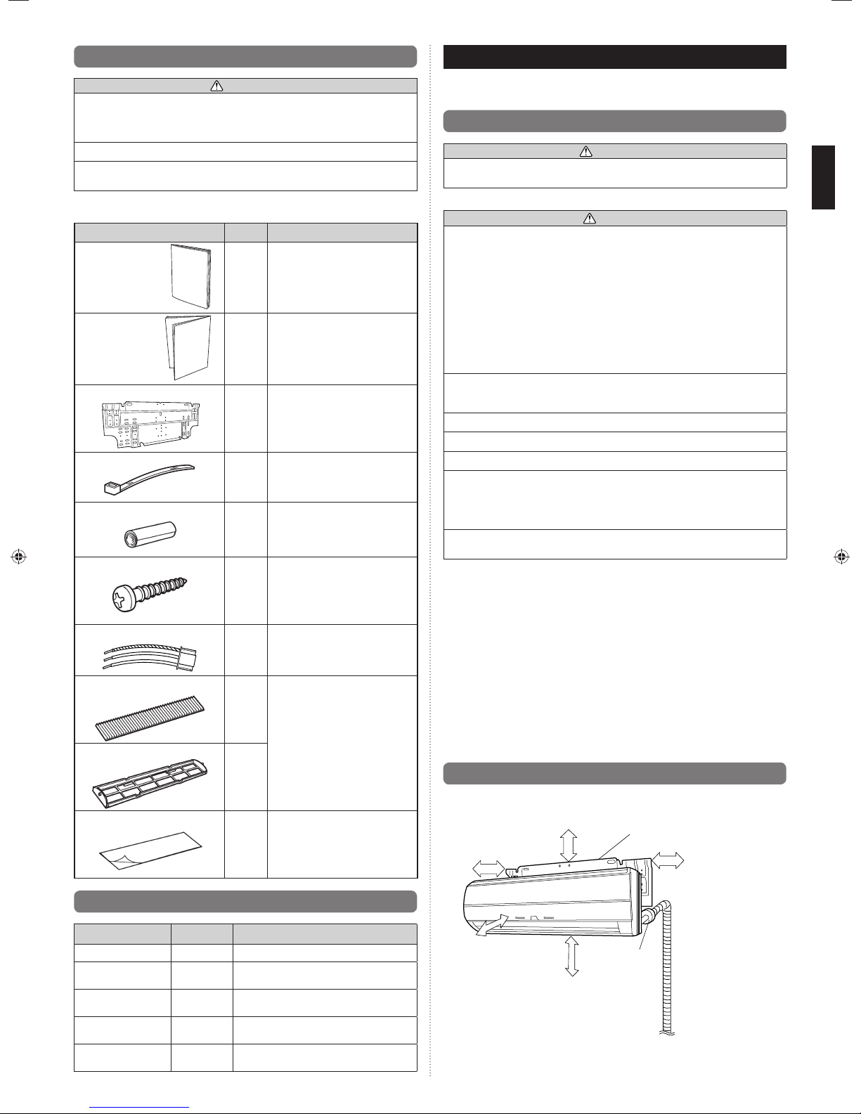
3.2. Installation dimensions
Seal A
For indoor unit installation
1
2.4. Optional parts
Description Part No. Application
External output wire B 9379529013 For output port
External input wire D 9368779016
External input wire F 9368779023
External input wire B 9368778002
Exter nal input wire E 9368778019
For control input port
(Apply voltage terminal)
For control input port
(Dry contact terminal)
For forced thermostat off port
(Apply voltage terminal)
For forced thermostat off port
(Dry contact terminal)
Provide a service space for inspection purposes.
Do not place any wiring or illumination in the service space, as they will impede service.
Wall hook bracket
50 mm or
60 mm or over
1,500 mm or over
1,800 mm or over
over
(Wall cap)
Drain hose
O.D 15.8 to 16.7 mm
I.D 13.8 mm
90 mm or
over
En-2
3.3. Installing the unit
WARNING
Install the air conditioner in a location which can withstand a load of at least 5 times the
weight of the main unit and which will not amplify sound or vibration. If the installation
location is not strong enough, the indoor unit may fall and cause injuries.
If the job is done with the panel frame only, there is a risk that the unit will come loose.
Please take care.
3.3.1. Determining the piping direction
The piping can be connected in the 5 directions indicated by 1, 2, 3, 4, and 5 in (Fig. A)
When the piping is connected in direction 2 or 5, cut along the piping groove in the
side of the front cover with a hacksaw.
When connecting the piping in direction 3, cut a notch in the thin wall at the front bottom of the front cover.
Fig. A
(Rear)
Left outlet
5
Rear outlet
Right outlet
2
Bottom outlet
3
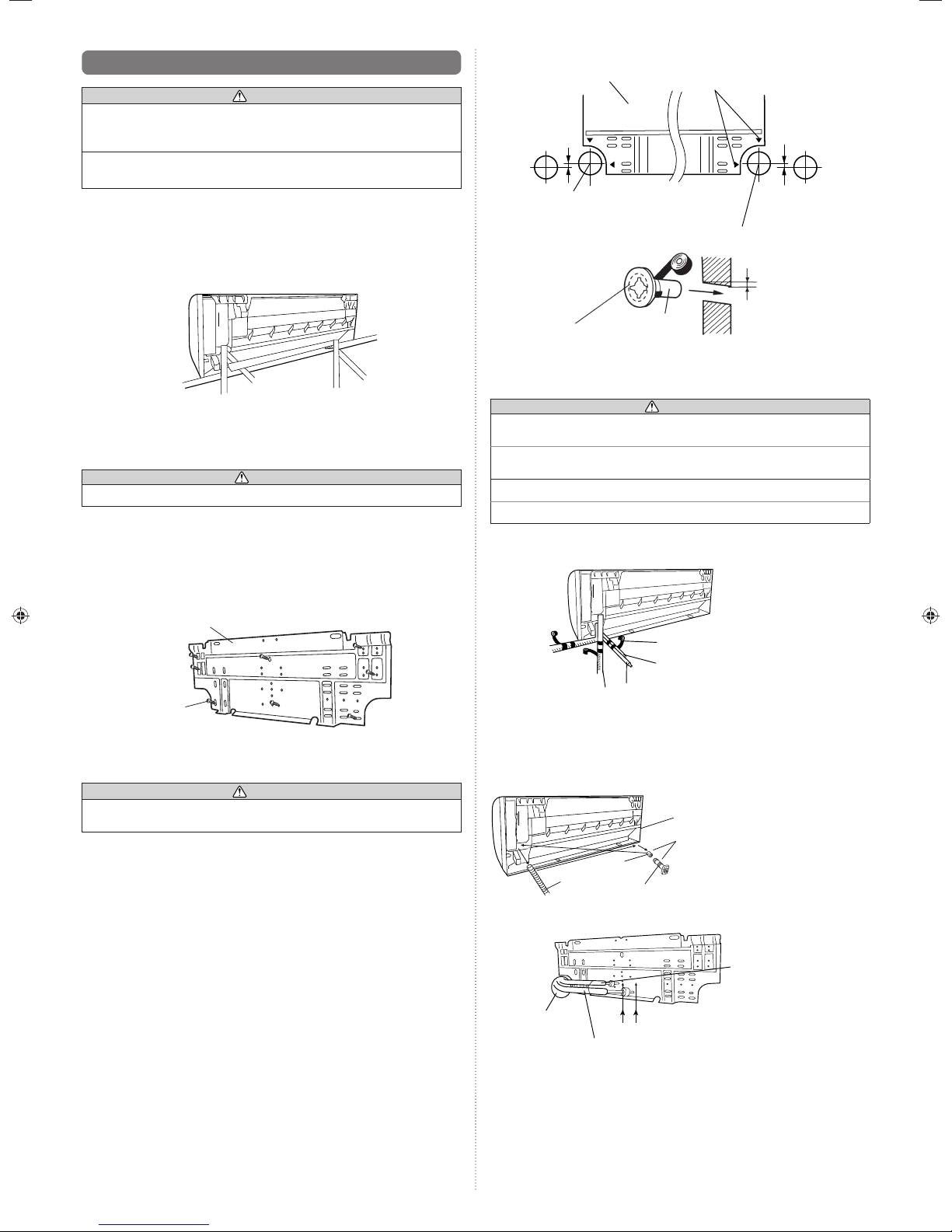
3.3.2. Installing the wall hook bracket
Install the wall hook bracket level, both horizontally and vertically.
(1) Install the wall hook bracket so that it is correctly positioned horizontally and
vertically. If the wall hook bracket is tiled, water will drip to the fl oor.
(2) Install the wall hook bracket so that it is strong enough to withstand the weight of an
adult.
• Fasten the wall hook bracket to the wall with 6 or more screws through the holes
near the outer edge of the bracket.
• Check that there is no rattle at the wall hook bracket.
Wall hook bracket
Tapping screw
3.3.3. Cutting the hole in the wall for the connecting piping
If the wall pipe is not used, the cable interconnecting the indoor and outdoor units may
touch metal and cause electric leakage.
(1) Cut a 80 mm diameter hole in the wall at the position shown in Fig. B.
(2) When cutting the wall hole at the inside of the wall hook bracket, cut the hole within
the range of the left and right center marks 40 mm below the wall hook bracket.
When cutting the wall hole at the outside of the wall hook bracket, cut the hole at
least 10 mm below over.
(3) Cut the hole so that the outside end is lower (5 to 10 mm) than the inside end.
(4) Always align the center of the wall hole. If misaligned, water leakage will occur.
(5) Cut the wall pipe to match the wall thickness, stick it into the wall cap, fasten the cap
with vinyl tape, and stick the pipe through the hole. (The connection pipe is supplied
in the installation set.) (Fig. B)
(6) For left piping and right piping, cut the hole a little lower so that drain water will fl ow
freely. (Fig. B)
1
CAUTION
WARNING
Left rear outlet
4
Fig. B
Wall hook bracket
Lower
80 mm dia. hole
.
Fasten with
vinyl tape
Wall cap*
Wall pipe*
(Inside) Wall
Center mark
5 to 10 mm
low
80 mm dia. hole
(Outside)
*Field supply
10 mm or
over
3.3.4. Forming the drain hose and pipe
CAUTION
In order to align the drain hose and drain cap, be sure to insert securely and vertically.
Incline insertion will cause water leakage.
When inserting, be sure not to attach any material besides water. If any other material
is attached, it will cause deterioration and water leakage.
After removing drain hose, be sure not to forget mounting drain cap.
Be sure to fi x the drain hose with tape to the bottom of piping.
[Rear piping, Right piping, Bottom piping]
(1) Install the indoor unit piping in the direction of the wall hole and bind the drain hose
and pipe together with vinyl tape.
Right piping
Bottom piping
(2) Install the piping so that the drain hose is at the bottom.
(3) Wrap the pipes of the indoor unit that are visible from the outside with decorative
tape.
[For Left rear piping, Left piping]
(1) Interchange the drain cap, insulation and the drain hose.
Insulation
Indoor unit
drain hose
(2) Align the marks on the wall hook bracket and shape the connection pipe.
Bend (R70) with a
pipe bender
Connection pipe (Gas pipe)
Bind with vinyl tape
Pipe (top) Rear piping
Indoor unit drain hose (bottom)
For left outlet piping, cut off the
piping outlet cutting groove with
a hacksaw.
Remove the drain cap by pulling
at the projection at the end of the
cap with pliers, etc.
Drain cap
And remove the insulation.
Align the marks.
Connection pipe
(Liquid pipe)
Lower
En-3
(3) Bend the connection piping at the bend radius of 70 mm or more and install no more
than 35 mm from the wall.
Installation method of Drain cap
Please put the heat insulation inside all along.
●
Use a hexagonal wrench (4mm at opposite side) to insert the drain cap, till the drain
●
cap contacts the tip of drain cock.
No gap
Hexagonal
wrench
[Removal method of drain hose]
Remove the screw at the left of drain hose and pull out drain hose.
Screw
Drain fi xture (blue)
[Installation method of drain hose]
Vertically insert the drain hose toward the inside, so that the drain fi xture (blue) can
accurately align with the screw hole around the drain cock.
After inserting and before replacing, please reinstall and fi x the removed screws.
Drain fi xture (blue)
Screw hole
No gap
Drain Cock
Insulation
Drain cap
Drain hose
Screw
Screws
(4 position)
Push
The front panel is pulled to the front, raising the upper surface, and a front panel
3
is removed.
(4) Insert the spacer, etc. between the indoor unit and the wall hook bracket and
separate the bottom of the indoor unit from the wall.
Indoor unit
Push
[▲]
mark
Wall hook bracket
Wall hook bracket
Front panel
Front panel
Spacer
Drain hose
Drain cock
Be sure to install around the drain hose connector.
As the screw is inside, be sure to use screwdriver treated with magnet.
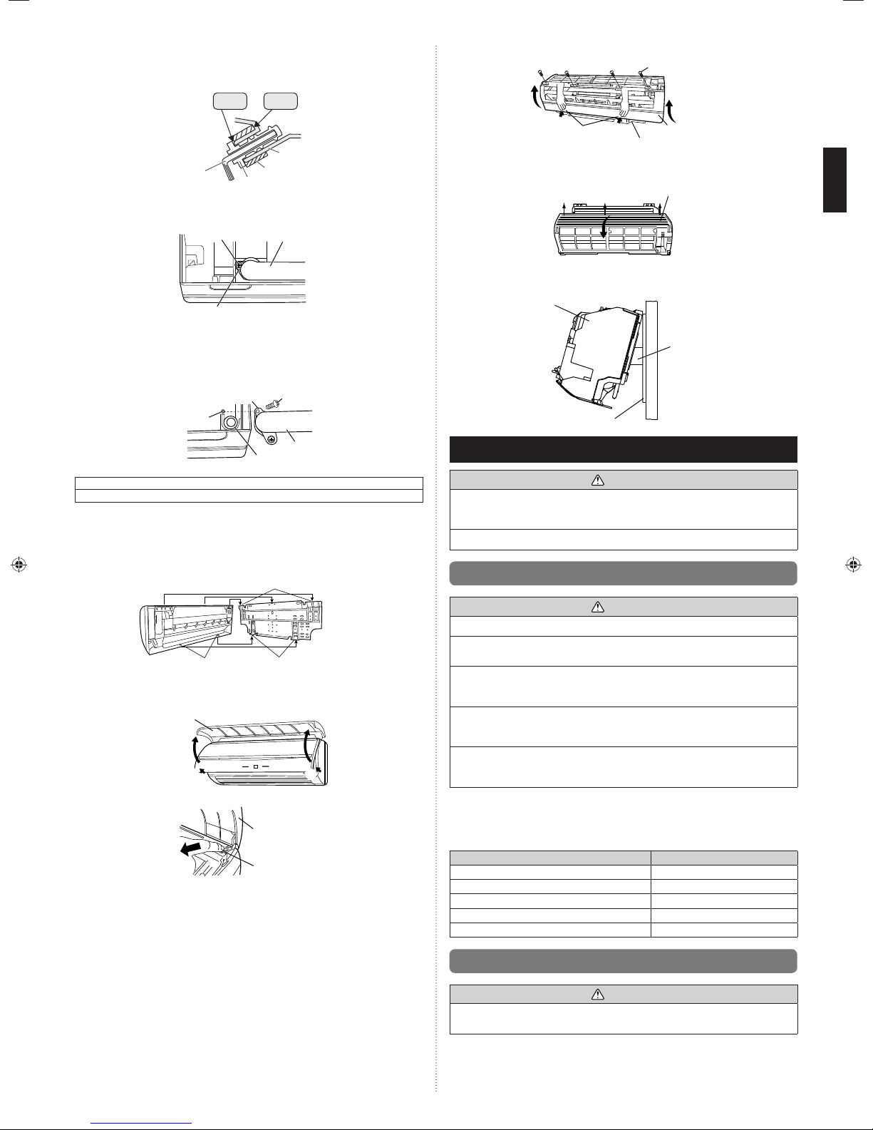
3.3.5. Installing the indoor unit
(1) After passing the indoor piping and drain hose through the wall hole, hang the indoor
unit on the hooks at the top and bottom of the wall hook bracket.
Connection pipe
(2 mm dia.)
Indoor unit
(2) Remove the intake grille.
Open the intake grille.
1
(Fitting)
Intake grille
2
1
Pull down the knob.
2
Lift the intake grille upward, until the axle at the top of the intake grille is removed.
3
(3) Remove the front panel.
The thumb is hung on the lower part as shown in the fi gure, and it pulls to the
1
front, pushing [▲] mark, and bottom hooks (2 position) is removed from wall hook
bracket.
The front panel bottom is pulled to the front, and bottom hooks is removed indoor
2
unit.
Top hooks
Wall hook bracket
Bottom hooks
2
1
Intake grille
Knob
4. PIPE INSTALLATION
CAUTION
Be more careful that foreign matter (oil, water, etc.) does not enter the piping than with
refrigerant R410A models. Also, when storing the piping, securely seal the openings
by pinching, taping, etc.
While welding the pipes, be sure to blow dry nitrogen gas through them.
4.1. Selecting the pipe material
CAUTION
Do not use existing pipes from another refrigeration system or refrigerant.
Use pipes that have clean external and internal sides without any contamination which
may cause trouble during use, such as sulfur, oxide, dust, cutting waste, oil, or water.
It is necessary to use seamless copper pipes.
Material : Phosphor deoxidized seamless copper pipes
It is desirable that the amount of residual oil is less than 40 mg/10 m.
Do not use copper pipes that have a collapsed, deformed, or discolored portion
(especially on the interior surface). Otherwise, the expansion valve or capillary tube
may become blocked with contaminants.
Improper pipe selection will degrade performance. As an air conditioner using R410A
incurs pressure higher than when using conventional (R22) refrigerant, it is necessary
to choose adequate materials.
Thicknesses of copper pipes used with R410A are as shown in the table.
•
Never use copper pipes thinner than those indicated in the table even if they are
•
available on the market.
Thicknesses of Annealed Copper Pipes (R410A)
Pipe outside diameter [mm (in.)] Thickness [mm]
6.35 (1/4) 0.80
9.52 (3/8) 0.80
12.70 (1/2) 0.80
15.88 (5/8) 1.00
19.05 (3/4) 1.20
4.2. Pipe requirement
CAUTION
Refer to the installation manual for the outdoor unit for description of allowable pipe
length and height difference.
Use pipe with water-resistant heat insulation.
En-4
 Loading...