

AirStage ARXK18GALH, ARXK12GALH, ARXK14GALH, ARXK09GALH, ARXK24GALH Installation Manual
...
TM
INSTALLATION MANUAL
ARXK07GALH
ARXK09GALH
ARXK12GALH
ARXK14GALH
ARXK18GALH
ARXK24GALH
(Without drain pump)
INDOOR UNIT (Duct type)
For authorized service personnel only.
INSTALLATIONSANLEITUNG
INNENGERÄT (Kanaltyp)
Nur für autorisiertes Fachpersonal.
MANUEL D’INSTALLATION
UNITÉ INTÉRIEURE (type conduit)
Pour le personnel agréé uniquement.
MANUAL DE INSTALACIÓN
UNIDAD INTERIOR (Tipo conducto)
Únicamente para personal de servicio autorizado.
MANUALE DI INSTALLAZIONE
UNITÀ INTERNA (tipo a condotto)
A uso esclusivo del personale tecnico autorizzato.
English
Deutsch
FrançaisEspañol
Italiano
ARXK07GCLH
ARXK09GCLH
ARXK12GCLH
ARXK14GCLH
ARXK18GCLH
ARXK24GCLH
(With drain pump)
ΕΓΧΕΙΡΙΔΙΟ ΕΓΚΑΤΑΣΤΑΣΗΣ
ΕΣΩΤΕΡΙΚΗ ΜΟΝΑΔΑ (Τύπος αγωγού)
Μόνο για εξουσιοδοτημένο τεχνικό προσωπικό.
MANUAL DE INSTALAÇÃO
UNIDADE INTERIOR (Tipo de tubagem)
Apenas para técnicos autorizados.
РУКОВОДСТВО ПО УСТАНОВКЕ
ВНУТРЕННИЙ МОДУЛЬ (Короб)
Только для авторизованного обслуживающего персонала.
MONTAJ KILAVUZU
İÇ ÜNİTE (Kanal tipi)
Yalnızca yetkili servis personeli için.
Refer to the rating label with the serial number.
MADE IN P.R.C.
ΕλληνικάPortuguês
РусскийTürkçe
[Original instructions]
PART NO. 9381858019
INSTALLATION MANUAL
PART NO. 9381858019
VRF system indoor unit (Duct type)
Contents
1. SAFETY PRECAUTIONS .........................................................................................1
2. ABOUT THIS PRODUCT..........................................................................................1
2.1. Precautions for using the R410A refrigerant ......................................................1
2.2. Special tool for R410A ....................................................................................... 1
2.3. Accessories ....................................................................................................... 2
2.4. Optional parts ....................................................................................................2
3. INSTALLATION WORK ............................................................................................ 2
3.1. Selecting an installation location .......................................................................2
3.2. Installation dimensions .....................................................................................3
3.3. Installation the unit ............................................................................................ 3
PIPE INSTALLATION ...............................................................................................5
4.
4.1. Selecting the pipe material ................................................................................5
4.2. Pipe requirement ...............................................................................................5
4.3. Flare connection (Pipe connection) ................................................................... 6
4.4. Installing heat insulation ....................................................................................6
5. INSTALLING DRAIN PIPES .....................................................................................7
5.1A. ARXK**GCLH model .......................................................................................7
5.1B. ARXK**GALH model ....................................................................................... 7
5.2. Install the drain pipe ..........................................................................................7
6. ELECTRICAL WIRING .............................................................................................9
6.1. Electrical requirement ........................................................................................ 9
6.2. Wiring method .................................................................................................10
6.3. Unit wiring ........................................................................................................10
6.4. Connection of wiring ........................................................................................ 11
6.5. External input and external output (Optional parts) ......................................... 11
6.6. Remote sensor (Optional parts) ......................................................................13
6.7. IR receiver unit (Optional parts) ....................................................................... 14
6.8. Auto louver grille (Optional parts) .................................................................... 14
6.9. Optional parts cable binding ............................................................................ 14
7. FIELD SETTING ..................................................................................................... 15
7.1. Setting the address .......................................................................................... 15
7.2. Custom code setting ........................................................................................ 16
7.3. Static pressure mode ....................................................................................... 16
7.4. Switching of airfl ow direction louver function ...................................................16
7.5. Function setting ...............................................................................................17
8. TEST RUN ..............................................................................................................17
8.1. Test run using Outdoor unit (PCB) .................................................................. 17
8.2. Test run using Remote Controller ....................................................................17
9. CHECK LIST ...........................................................................................................17
10. ERROR CODES .....................................................................................................18
This mark indicates procedures which, if improperly performed,
CAUTION
Read carefully all security information before use or install the air conditioner.
Do not attempt to install the air conditioner or a part of the air conditioner by yourself.
This unit must be installed by qualified personnel with a capacity certificate for handling
refrigerant fluids. Refer to regulation and laws in use on installation place.
The installation must be carried out in compliance with regulations in force in the place of
installation and the installation instructions of the manufacturer.
This unit is part of a set constituting an air conditioner. It must not be installed alone or
with non-authorized by the manufacturer.
Always use a separate power supply line protected by a circuit breaker operating on all
wires with a distance between contact of 3mm for this unit.
The unit must be correctly grounded and the supply line must be equipped with a
differential breaker in order to protect the persons.
The units are not explosion proof and therefore should not be installed in explosive
atmosphere.
Never touch electrical components immediately after the power supply has been turned
off. Electric shock may occur. After turning off the power, always wait 5 minutes before
touching electrical components.
This unit contains no user-serviceable parts. Always consult authorized service
personnel to repairs.
When moving, consult authorized service personnel for disconnection and installation of
the unit.
might possibly result in personal harm to the user, or damage to
property.
2. ABOUT THIS PRODUCT
2.1. Precautions for using the R410A refrigerant
WARNING
Do not introduce any substance other than the prescribed refrigerant into the
refrigeration cycle.
If air enters the refrigeration cycle, the pressure in the refrigeration cycle will become
abnormally high and cause the piping to rupture.
If there is a refrigerant leakage, make sure that it does not exceed the concentration
limit.
If a refrigerant leakage exceeds the concentration limit, it can lead to accidents such as
oxygen starvation.
Do not touch refrigerant that has leaked from the refrigerant pipe connections or other
area. Touching the refrigerant directly can cause frostbite.
If a refrigerant leakage occurs during operation, immediately vacate the premises and
thoroughly ventilate the area.
If the refrigerant comes in contact with a fl ame, it produces a toxic gas.
1. SAFETY PRECAUTIONS
• Be sure to read this Manual thoroughly before installation.
• The warnings and precautions indicated in this Manual contain important information
pertaining to your safety. Be sure to observe them.
• Hand this Manual, together with the Operating Manual to the customer.
Request the customer to keep them on hand for future use, such as for relocating or
repairing the unit.
WARNING
Request your dealer or a professional installer to install the unit in accordance with this
Manual.
An improperly installed unit can cause serious accidents such as water leakage,
electric shock, or fi re.
If the unit is installed in disregard of the instructions in the Installation Manual, it will
void the manufacturer’s warranty.
Do not turn ON the power until all work has been completed.
Turning ON the power before the work is completed can cause serious accidents such
as electric shock or fi re.
If refrigerant leaks while work is being carried out, ventilate the area.
If the refrigerant comes in contact with a fl ame, it produces a toxic gas.
Installation work must be performed in accordance with national wiring standards by
authorized personnel only.
Except for EMERGENCY, never turn off main as well as sub breaker of the indoor units
during operation. It will cause compressor failure as well as water leakage.
First, stop the indoor unit by operating the control unit, converter or external input
device and then cut the breaker.
Make sure to operate through the control unit, converter or external input device.
When the breaker is designed, locate it at a place where the users cannot start and
stop in the daily work.
This mark indicates procedures which, if improperly performed,
might lead to the death or serious injury of the user.
2.2. Special tool for R410A
WARNING
To install a unit that uses the R410A refrigerant, use dedicated tools and piping
materials that have been manufactured specifi cally for R410A use.
Because the pressure of the R410A refrigerant is approximately 1.6 times higher than
the R22, failure to use dedicated piping material or improper installation can cause
rupture or injury.
Furthermore, it can cause serious accidents such as water leakage, electric shock, or
fi re.
Tool name Contents of change
Pressure is huge and cannot be measured with a
conventional (R22) gauge. To prevent erroneous mixing
Gauge manifold
Charging hose
Vacuum pump
Gas leakage detector Special gas leakage detector for HFC refrigerant R410A.
of other refrigerants, the diameter of each port has been
changed.
It is recommended to use a gauge manifold with a high
pressure display range –0.1 to 5.3 MPa and a low pressure
display range –0.1 to 3.8 MPa.
To increase pressure resistance, the hose material and base
size were changed.
A conventional (R22) vacuum pump can be used by installing
a vacuum pump adapter.
Be sure that the pump oil does not backflow into the system.
Use one capable for vacuum suction of –100.7 kPa (5 Torr,
–755 mmHg).
En-1
2.3. Accessories
WARNING
For installation purposes, be sure to use the parts supplied by the manufacturer or
other prescribed parts.
The use of non-prescribed parts can cause serious accidents such as the unit to fall,
water leakage, electric shock, or fi re.
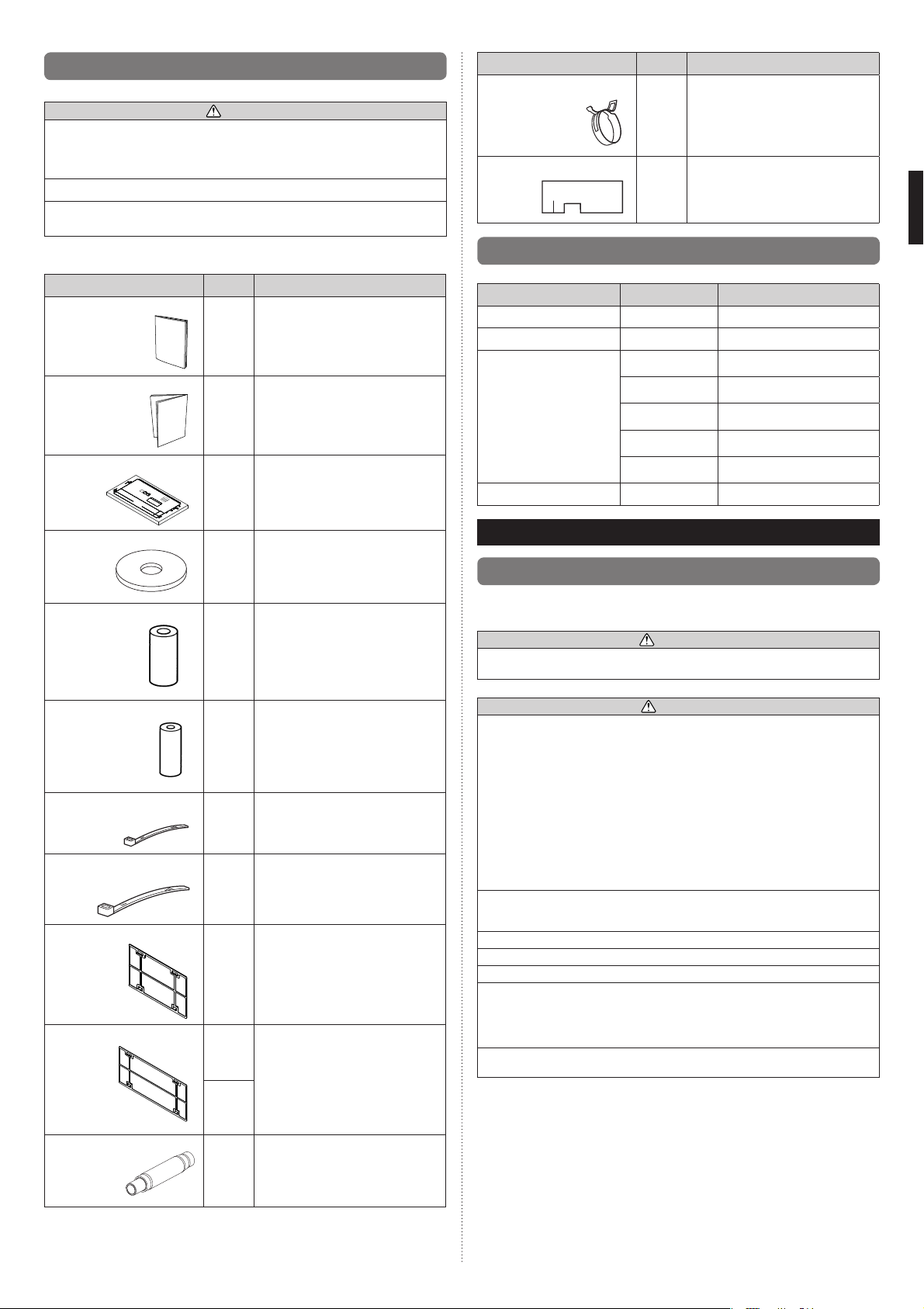
The following installation parts are furnished. Use them as required.
Keep the Installation Manual in a safe place and do not discard any other accessories
until the installation work has been completed.
Name and Shape Q’ty Application
Hose band
Drain hose insulation B
For installing drain hose
1
Insulates the drain hose
1
Do not discard any accessories needed for installation until the installation work has
been completed.
Name and Shape Q’ty Application
Operating manual
1
Installation manual
Template (Carton top)
Washer
Coupler heat insulation (Large)
(This book)
1
For ceiling openings cutting Also used as
packing
1
For installing indoor unit
8
For indoor side pipe joint (Large pipe)
1
2.4. Optional parts
Description Model Application
IR receiver unit UTB-*WC For the wireless remote controller.
Remote sensor UTY-XSZX Room temperature sensor
UTY-XWZXZC
UTY-XWZXZB
External connect kit
Auto louver grille UTD-GXT*-W For Auto louver grille
UTY-XWZXZD
UTY-XWZXZ7
UTY-XWZXZE
For output function
(Output terminal / CNB01)
For control input function
(Apply voltage terminal / CNA01)
For control input function
(Dry contact terminal / CNA02)
For forced thermostat off function
(Apply voltage terminal / CNA03)
For forced thermostat off function
(Dry contact terminal / CNA04)
3. INSTALLATION WORK
3.1. Selecting an installation location
Correct initial installation location is important because it is diffi cult to move unit after it is
installed.
WARNING
Select installation locations that can properly support the weight of the indoor. Install
the units securely so that they do not topple or fall.
Coupler heat insulation (Small)
Cable tie (Medium)
Cable tie (Large)
Filter (Small)
Filter (Big)
Drain hose
1
2
4
2
(AR07/09/
12/14/24)
2 (AR18)
1 (AR24)
1
For indoor side pipe joint (Small pipe)
For transmission and remote controller
cable binding
For fixing the coupler heat insulation.
For installing drain pipe VP25
(O.D.32, I.D.25)
CAUTION
Do not install the unit in the following areas:
• Area with high salt content, such as at the seaside.
It will deteriorate metal parts, causing the parts to fail or the unit to leak water.
• Area fi lled with mineral oil or containing a large amount of splashed oil or steam,
such as a kitchen.
It will deteriorate plastic parts, causing the parts to fail or the unit to leak water.
• Area that generates substances that adversely affect the equipment, such as sulfuric
gas, chlorine gas, acid, or alkali.
It will cause the copper pipes and brazed joints to corrode, which can cause
refrigerant leakage.
• Area that can cause combustible gas to leak, contains suspended carbon fi bers or
fl ammable dust, or volatile infl ammables such as paint thinner or gasoline.
If gas leaks and settles around the unit, it can cause a fi re.
• Area where animals may urinate on the unit or ammonia may be generated.
Do not use the unit for special purposes, such as storing food, raising animals, growing
plants, or preserving precision devices or art objects.
It can degrade the quality of the preserved or stored objects.
Do not install where there is the danger of combustible gas leakage.
Do not install the unit near a source of heat, steam, or fl ammable gas.
Install the unit where drainage does not cause any trouble.
Install the indoor unit, power supply cable, transmission cable, and remote controller
cable at least 1 m away from a television or radio receivers. The purpose of this is to
prevent TV reception interference or radio noise.
(Even if they are installed more than 1 m apart, you could still receive noise under
some signal conditions.)
If children under 10 years old may approach the unit, take preventive measures so that
they cannot reach the unit.
En-2
• Decide the mounting position with the customer as follows:
(1) Install the indoor unit on a place having a suffi cient strength so that it withstands
against the weight of the indoor unit.
(2) The inlet and outlet ports should not be obstructed; the air should be able to blow all
over the room.
(3) Leave the space required to service the air conditioner.
(4) A place from where the air can be distributed evenly throughout the room by the unit.
(5) Install the unit where connection to the outdoor unit is easy.
(6) Install the unit where the connection pipe can be easily installed.
(7) Install the unit where the drain pipe can be easily installed.
(8) Install the unit where noise and vibrations are not amplifi ed.
(9) Take servicing, etc., into consideration and leave the spaces. Also install the unit
where the fi lter can be removed.
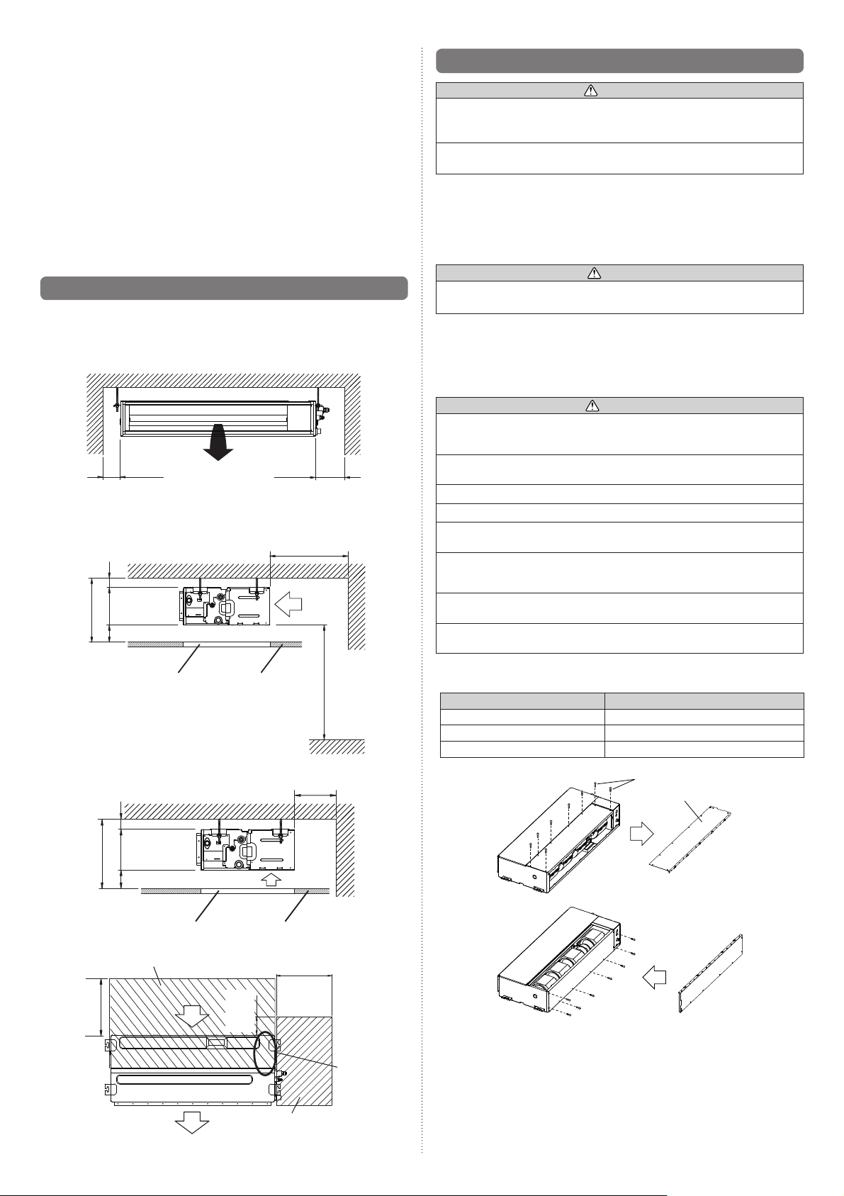
3.2. Installation dimensions
Provide a service access for inspection purposes.
Do not place any wiring or illumination in the service space, as they will impede service.
Installation Dimensions
Strong and durable ceiling
Left
side
150 mm or
more 1
1 400mm or more when drain from drain pipe
• When intaking air from back
5 mm or more
20 mm or more
225 mm or more
Service access Ceiling
Indoor unit
400 mm
or more
300 mm or more
Air
2500 mm or more
Floor
Right
side
(When no ceiling)
3.3. Installation the unit
WARNING
Install the air conditioner in a location which can withstand a load of at least 5 times the
weight of the main unit and which will not amplify sound or vibration. If the installation
location is not strong enough, the indoor unit may fall and cause injuries.
If the job is done with the panel frame only, there is a risk that the unit will come loose.
Please take care.
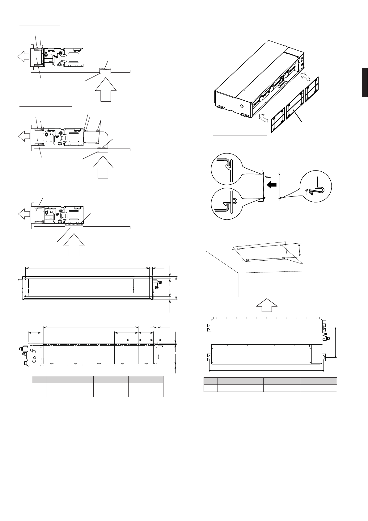
3.3.1. Unit installation example
Connect the locally purchased duct.
(1) Inlet side
• Connect the duct to the locally purchased inlet fl ange.
• Connect the fl ange to the body with the locally purchased tapping screws.
• Wind the inlet fl ange connecting to the duct with the aluminum tape etc. to avoid the
air leakage.
CAUTION
When the duct is connected to inlet side, remove contained fi lter and surely attach
locally purchased fi lter at inlet opening.
(2) Outlet side
• Connect the duct with adjusting inside of outlet fl ange.
• Wind the outlet fl ange connecting to the duct with the aluminum tape etc. to avoid the
air leakage.
• Insulate the duct to avoid the dew condensation.
CAUTION
To prevent people from touching the parts inside the unit, be sure to install grilles on
the inlet and outlet ports. The grilles must be designed in such a way that cannot be
removed without tools.
Check that duct work does not exceed the range of external static pressure of
equipment.
Make sure to insulate ducts to avoid the dew condensation.
Make sure to insulate between ducts and walls if metal ducts are used.
Please explain handling and washing methods of locally purchased materials to the
customer.
To prevent people from touching the parts inside the unit, be sure to install grilles on
the inlet and outlet ports. The grilles must be designed in such a way that cannot be
removed without tools.
When connecting the duct to the outlet port of the indoor unit, be sure to insulate the
outlet port and the installation screws to prevent water from leaking around the port.
Set the static pressure of AR07/09/12 model to 0 to 30 Pa.
Set the static pressure of AR14/18/24 model to 0 to 50 Pa.
Replace the cover as follows.
• Remove the screws, and then remove cover.
• Install the cover with the screws as shown in the illustration below.
Model Screw
AR07/09/12/14 6
AR18 7
AR24 8
• When intaking air from bottom
5 mm or more
20 mm or more
225 mm or more
Service access
Adjust the wind direction in the room depending on the shape of blow out opening.
[ Top view ]
300 mm
or more*
Service space
Air
100 mm
Air
*: Above 100mm When intaking air from bottom
100 mm or more
Air
Ceiling
400 mm or more
or more
Service access
En-3
Control
box
screw
Cover
Side Inlet - Side Outlet
Insulation material (Locally purchased)
Aluminum tape
Flange (Locally purchased)
3.3.2. Install the fi lters
• Install the fi lters to the unit.
Air
Duct (Locally
purchased)
Side Inlet - Side Outlet (Duct)
Insulation material (Locally purchased)
Bottom Inlet - Side Outlet
Outlet side
Aluminum tape
Flange (Locally purchased)
Air
Duct (Locally
purchased)
Duct (Locally purchased)
Air
Intake grille
(Locally purchased)
Intake grille
(Locally
purchased)
Intake grille
(Locally
purchased)
Air
Filter (Locally purchased)
Air
Flange (Locally purchased)
Aluminum tape
Tapping screw for fl ange
connection (M4 x 10mm/
Locally purchased)
Filter
(Locally purchased)
Air
Filter
A
25 mm
19 mm
AR07/09/12/14/18: 2 fi lters
AR24: 3 fi lters
Unit
3.3.3.
Drilling holes for bolts and installing the bolts
• Using the installation template, drill holes for bolts (4 holes).
Installation template
Filter
Filter (Accessories)
Drilling position
for bolts
Inlet side
109 mm
B
70 mm
AR07/09/12/14 AR18 AR24
A 650 mm 850 mm 1050 mm
B P200×2=400 mm P200×3=600 mm P200×4=800 mm
P200
130 mm
15 mm
38 mm
198 mm
25 mm
11 mm
11 mm
Air
295 mm
A
AR07/09/12/14 AR18 AR24
A 752 mm 952 mm 1152 mm
En-4
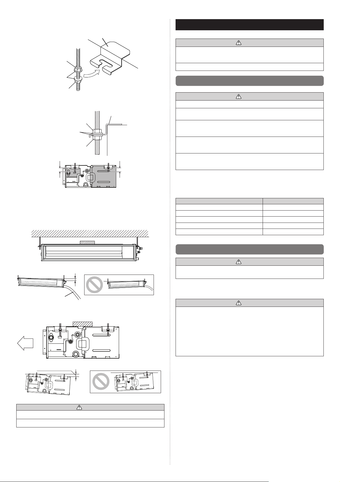
3.3.4. Fix the unit
(1) Hang the unit
Hanger
Hanger bolt
Nut A
(Locally purchased)
Washer
(Accessories)
Nut B
(Locally
purchased)
Hanger bolt
Nut A
(Locally purchased)
Washer
(Accessories)
Nut B
(Locally purchased)
20 mm
or less
If the length of hanger bolt is over 20 mm, it will be not convenient for following works:
• The opening and closing of control box cover
• Replacement of drain pump
(2) Leveling
Base horizontal direction leveling on top of the unit.
Ceiling
Level
Hanger
Unit
20 mm
or less
4. PIPE INSTALLATION
CAUTION
Be more careful that foreign matter (oil, water, etc.) does not enter the piping than with
refrigerant R410A models. Also, when storing the piping, securely seal the openings by
pinching, taping, etc.
While welding the pipes, be sure to blow dry nitrogen gas through them.
4.1. Selecting the pipe material
CAUTION
Do not use existing pipes from another refrigeration system or refrigerant.
Use pipes that have clean external and internal sides without any contamination which
may cause trouble during use, such as sulfur, oxide, dust, cutting waste, oil, or water.
It is necessary to use seamless copper pipes.
Material : Phosphor deoxidized seamless copper pipes
It is desirable that the amount of residual oil is less than 40 mg/10 m.
Do not use copper pipes that have a collapsed, deformed, or discolored portion
(especially on the interior surface). Otherwise, the expansion valve or capillary tube
may become blocked with contaminants.
Improper pipe selection will degrade performance. As an air conditioner using R410A
incurs pressure higher than when using conventional (R22) refrigerant, it is necessary
to choose adequate materials.
Thicknesses of copper pipes used with R410A are as shown in the table.
•
Never use copper pipes thinner than those indicated in the table even if they are
•
available on the market.
Thicknesses of Annealed Copper Pipes (R410A)
Pipe outside diameter [mm (in)] Thickness [mm]
6.35 (1/4) 0.80
9.52 (3/8) 0.80
12.70 (1/2) 0.80
15.88 (5/8) 1.00
19.05 (3/4) 1.20
GOOD PROHIBITED
Drain hose
Give a slight tilt to the side to which the drain hose is connected. The tilt should be in the
range of 0 mm to 10 mm.
Air
GOOD PROHIBITED
5 mm or less
10 mm or less
Level
CAUTION
Leave a space of 100 mm or more between the inlet port and the ceiling.
Fasten the unit securely with nuts A and B.
4.2. Pipe requirement
CAUTION
Refer to the Installation Manual of the outdoor unit for description of the length of
connecting pipe or for difference of its elevation.
• Use pipe with water-resistant heat insulation.
CAUTION
Install heat insulation around both the gas and liquid pipes. Failure to do so may cause
water leaks.
Use heat insulation with heat resistance above 120 °C. (Reverse cycle model only)
In addition, if the humidity level at the installation location of the refrigerant piping is
expected to exceed 70 %, install heat insulation around the refrigerant piping. If the
expected humidity level is 70 to 80 %, use heat insulation that is 15 mm or thicker and
if the expected humidity exceeds 80 %, use heat insulation that is 20 mm or thicker.
If heat insulation is used that is not as thick as specifi ed, condensation may form on
the surface of the insulation. In addition, use heat insulation with heat conductivity of
0.045 W/(m·K) or less (at 20 °C).
En-5
 Loading...