

AirStage AGHA009GCAH, AGHA004GCAH, AGYA007GCAH, AGYA009GCAH, AGHA012GCAH Installation Manual
...
TM
INSTALLATION MANUAL
EEV internal model
AGYA004GCAH/AGHA004GCAH
AGYA007GCAH/AGHA007GCAH
AGYA009GCAH/AGHA009GCAH
AGYA012GCAH/AGHA012GCAH
AGYA014GCAH/AGHA014GCAH
EEV external model
AGYE004GCAH/AGHE004GCAH
INDOOR UNIT (Floor type)
For authorized service personnel only.
INSTALLATIONSANLEITUNG
INNENGERÄT (Fußbodentyp)
Nur für autorisiertes Fachpersonal.
MANUEL D’INSTALLATION
UNITÉ INTÉRIEURE (Type sol)
Pour le personnel agréé uniquement.
MANUAL DE INSTALACIÓN
UNIDAD INTERIOR (Tipo suelo)
Únicamente para personal de servicio autorizado.
MANUALE DI INSTALLAZIONE
UNITÀ INTERNA (Tipo da pavimento)
A uso esclusivo del personale tecnico autorizzato.
English
Deutsch
FrançaisEspañol
Italiano
AGYE007GCAH/AGHE007GCAH
AGYE009GCAH/AGHE009GCAH
AGYE012GCAH/AGHE012GCAH
AGYE014GCAH/AGHE014GCAH
ΕΓΧΕΙΡΙΔΙΟ ΕΓΚΑΤΑΣΤΑΣΗΣ
ΕΣΩΤΕΡΙΚΗ ΜΟΝΑΔΑ (Τύπος δαπέδου)
Μόνο για εξουσιοδοτημένο τεχνικό προσωπικό.
MANUAL DE INSTALAÇÃO
UNIDADE INTERIOR (Tipo de chão)
Apenas para técnicos autorizados.
РУКОВОДСТВО ПО УСТАНОВКЕ
ВНУТРЕННИЙ МОДУЛЬ (Напольный тип)
Только для авторизованного обслуживающего персонала.
MONTAJ KILAVUZU
İÇ ÜNİTE (Yer tipi)
Yalnızca yetkili servis personeli için.
Refer to the rating label with the serial number.
MADE IN P.R.C.
ΕλληνικάPortuguês
РусскийTürkçe
[Original instructions]
PART No. 9382568016
INSTALLATION MANUAL
PART NO. 9382568016
VRF system indoor unit (Floor type)
Contents
1. SAFETY PRECAUTIONS ........................................................................................... 1
2. ABOUT THIS PRODUCT ............................................................................................ 1
2.1. Precautions for using R410A refrigerant .............................................................. 1
2.2. Special tools for R410A ....................................................................................... 1
2.3. Accessories ......................................................................................................... 2
2.4. Optional parts ...................................................................................................... 2
3. INSTALLATION WORK .............................................................................................. 2
3.1. Selecting an installation location .......................................................................... 2
3.2. Installation dimension .......................................................................................... 3
3.3. Indoor unit piping direction ................................................................................... 3
3.4. Side panel L, R removal and installation .............................................................3
3.5. Cutting the hole in the wall for the connecting piping ..........................................3
3.6. Indoor unit installation .......................................................................................... 4
3.7. Installing the wall hook bracket ............................................................................ 4
4. PIPE INSTALLATION .................................................................................................. 4
4.1. Selecting the pipe material ..................................................................................4
4.2. Pipe requirement ................................................................................................. 5
4.3. Flare connection (pipe connection) ...................................................................... 5
4.4. Forming piping .....................................................................................................5
4.5. Note on drain hose ..............................................................................................5
5. ELECTRICAL WIRING ................................................................................................6
5.1. Electrical requirement ..........................................................................................6
5.2. Wiring method ...................................................................................................... 7
5.3. Unit wiring ............................................................................................................7
5.4. Wiring ...................................................................................................................8
6. FINISHING................................................................................................................... 9
6.1. Connection pipe, cable and drain hose ...............................................................9
7. FIELD SETTING .......................................................................................................... 9
7.1. Side panel L and control cover removal ............................................................... 9
7.2. Setting the address .............................................................................................. 9
7.3. Custom code setting .......................................................................................... 10
7.4. Function setting ................................................................................................. 10
7.5. External input and external output (Optional parts) ........................................... 11
8. TEST RUN ................................................................................................................. 13
8.1. Test run using Outdoor unit (PCB) ..................................................................... 13
8.2. Test run using remote controller ........................................................................ 13
9. CHECK LIST .............................................................................................................13
10. ERROR CODES ........................................................................................................ 14
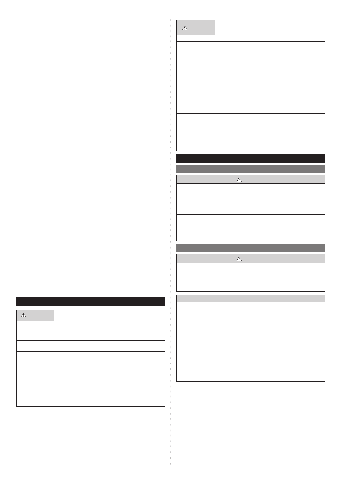
This mark indicates procedures which, if improperly performed,
CAUTION
Read carefully all security information before use or install the air conditioner.
Do not attempt to install the air conditioner or a part of the air conditioner by yourself.
This unit must be installed by qualified personnel with a capacity certificate for handling
refrigerant fluids. Refer to regulation and laws in use on installation place.
The installation must be carried out in compliance with regulations in force in the place
of installation and the installation instructions of the manufacturer.
This unit is part of a set constituting an air conditioner. It must not be installed alone or
with non-authorized by the manufacturer.
Always use a separate power supply line protected by a circuit breaker operating on all
wires with a distance between contact of 3 mm for this unit.
The unit must be correctly earthed (grounded) and the supply line must be equipped
with a differential breaker in order to protect the persons.
The units are not explosion proof and therefore should not be installed in explosive
atmosphere.
Never touch electrical components immediately after the power supply has been turned
off. Electric shock may occur. After turning off the power, always wait 5 minutes before
touching electrical components.
This unit contains no user-serviceable parts. Always consult authorized service personnel to repairs.
When moving, consult authorized service personnel for disconnection and installation
of the unit.
might possibly result in personal harm to the user, or damage
to property.
2. ABOUT THIS PRODUCT
2.1. Precautions for using R410A refrigerant
WARNING
Do not introduce any substance other than the prescribed refrigerant into the refrigeration cycle. If air enters the refrigeration cycle, the pressure in the refrigeration cycle will
become abnormally high and cause the piping to rupture.
If there is a refrigerant leak, make sure that it does not exceed the concentration limit.
If a refrigerant leak exceeds the concentration limit, it can lead to accidents such as
oxygen starvation.
Do not touch refrigerant that has leaked from the refrigerant pipe connections or other
area. Touching the refrigerant directly can cause frostbite.
If a refrigerant leak occurs during operation, immediately vacate the premises and thoroughly ventilate the area. If the refrigerant comes in contact with a flame, it produces a
toxic gas.
2.2. Special tools for R410A
WARNING
To install a unit that uses R410A refrigerant, use dedicated tools and piping materials that have been manufactured specifically for R410A use. Because the pressure
of R410A refrigerant is approximately 1.6 times higher than the R22, failure to use
dedicated piping material or improper installation can cause rupture or injury.
Furthermore, it can cause serious accidents such as water leakage, electric shock, or
fire.
1. SAFETY PRECAUTIONS
WARNING
Request your dealer or a professional installer to install the indoor unit in accordance
with this Installation Manual. An improperly installed unit can cause serious accidents
such as water leakage, electric shock, or fire. If the indoor unit is installed in disregard of
the instructions in the Installation Manual, it will void the manufacturer’s warranty.
Do not turn ON the power until all work has been completed. Turning ON the power
before the work is completed can cause serious accidents such as electric shock or fire.
If refrigerant leaks while work is being carried out, ventilate the area. If the refrigerant
comes in contact with a flame, it produces a toxic gas.
Installation work must be performed in accordance with national wiring standards by
authorized personnel only.
Except for EMERGENCY, never turn off main as well as sub breaker of the indoor units
during operation. It will cause compressor failure as well as water leakage.
First, stop the indoor unit by operating the controller, converter or external input device
and then cut the breaker.
Make sure to operate through the controller, converter or external input device.
When the breaker is designed, locate it at a place where the users cannot start and stop
in the daily work.
This mark indicates procedures which, if improperly performed,
might lead to the death or serious injury of the user.
Tool name Contents of change for R22 tool
Pressure is huge and cannot be measured with a conventional gauge. To prevent erroneous mixing of other refriger-
Gauge manifold
Charging hose
Vacuum pump
Gas leakage detector Special gas leakage detector for HFC refrigerant R410A.
ants, the diameter of each port has been changed.
It is recommended to use a gauge manifold with a high
pressure display range -0.1 to 5.3 MPa and a low pressure
display range -0.1 to 3.8 MPa.
To increase pressure resistance, the hose material and base
size were changed.
A conventional vacuum pump can be used by installing a
vacuum pump adapter.
• A conventional vacuum pump can be used by installing a
vacuum pump adapter.
• Be sure that the pump oil does not back flow into the
system. Use one capable for vacuum suction of -100.7kPa
(5 Ton, -755mmHg).
En-1
2.3. Accessories
WARNING
For installation purposes, be sure to use the parts supplied by the manufacturer or other
prescribed parts.
The use of non-prescribed parts can cause serious accidents such as the unit falling,
water leakage, electric shock, or fire.
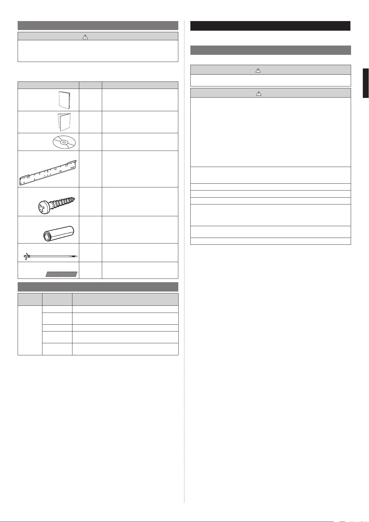
• The following installation parts are furnished. Use them as required.
• Keep the Installation Manual in a safe place and do not discard any other accessories
until the installation work has been completed.
Name and Shape Q’ty Application
Operating
Manual
Installation
Manual
Operating
Manual
(CD-ROM)
Wall hook bracket
Tapping screw (M4 × 25 mm)
Cloth tape
Push mount cable tie
Air cleaning filter
1
(This book)
1
1
For indoor unit installation.
1
For wall hook bracket installation.
9
For indoor unit installation.
1
For transmission and remote controller
cable binding
1
For installation, refer to the “CLEANING
AND CARE” in the operating manual.
2
2.4. Optional parts
Descrip-
tion
External
connect kit
Model Application
UTY-XWZXZC For output function (Output terminal / CNB01)
UTY-XWZXZB
UTY-XWZXZD For control input function (Dry contact terminal / CNA02)
UTY-XWZXZ7
UTY-XWZXZE
For control input function (Apply voltage terminal /
CNA01)
For forced thermostat off function (Apply voltage terminal
/ CNA03)
For forced thermostat off function (Dry contact terminal
/ CNA04)
3. INSTALLATION WORK
Correct initial installation location is important because it is difficult to move unit after it is
installed.
3.1. Selecting an installation location
Decide the mounting position together with the customer as follows.
WARNING
Select installation locations that can properly support the weight of the indoor unit.
Install the units securely so that they do not topple or fall.
CAUTION
Do not install the indoor unit in the following areas:
• Area with high salt content, such as at the seaside. It will deteriorate metal parts, causing the parts to fail or the unit to leak water.
• Area filled with mineral oil or containing a large amount of splashed oil or steam, such
as a kitchen. It will deteriorate plastic parts, causing the parts to fail or the unit to leak
water.
• Area that generates substances that adversely affect the equipment, such as sulfuric
gas, chlorine gas, acid, or alkali. It will cause the copper pipes and brazed joints to
corrode, which can cause refrigerant leakage.
• Area that can cause combustible gas to leak, contains suspended carbon fibers or
flammable dust, or volatile inflammables such as paint thinner or gasoline. If gas leaks
and settles around the unit, it can cause a fire.
• Area where animals may urinate on the unit or ammonia may be generated.
Do not use the unit for special purposes, such as storing food, raising animals, growing
plants, or preserving precision devices or art objects.
It can degrade the quality of the preserved or stored objects.
Do not install where there is the danger of combustible gas leakage.
Do not install the unit near a source of heat, steam, or flammable gas.
Install the unit where drainage does not cause any trouble.
Install the indoor unit, power supply cable, transmission cable, and remote controller
cable at least 1 m away from a television or radio receivers. The purpose of this is to
prevent TV reception interference or radio noise. (Even if they are installed more than 1
m apart, you could still receive noise under some signal conditions.)
If children under 10 years old may approach the unit, take preventive measures so that
they cannot reach the unit.
Take precautions to prevent the unit from falling.
(1) Install the indoor unit on a place having a sufficient strength so that it withstands
against the weight of the indoor unit.
(2) The inlet and outlet ports should not be obstructed; the air should be able to blow all
over the room.
(3) Leave the space required to service the air conditioner.
(4) Install the unit where connection to the outdoor unit (or RB unit) is easy.
(5) Install the unit where the connection pipe can be easily installed.
(6) Install the unit where the drain pipe can be easily installed.
(7) Install the unit where noise and vibrations are not amplified.
(8) Take servicing, etc., into consideration and leave the spaces. Also install the unit
where the filter can be removed.
(9) Do not install the unit where it will be exposed to direct sunlight.
En-2
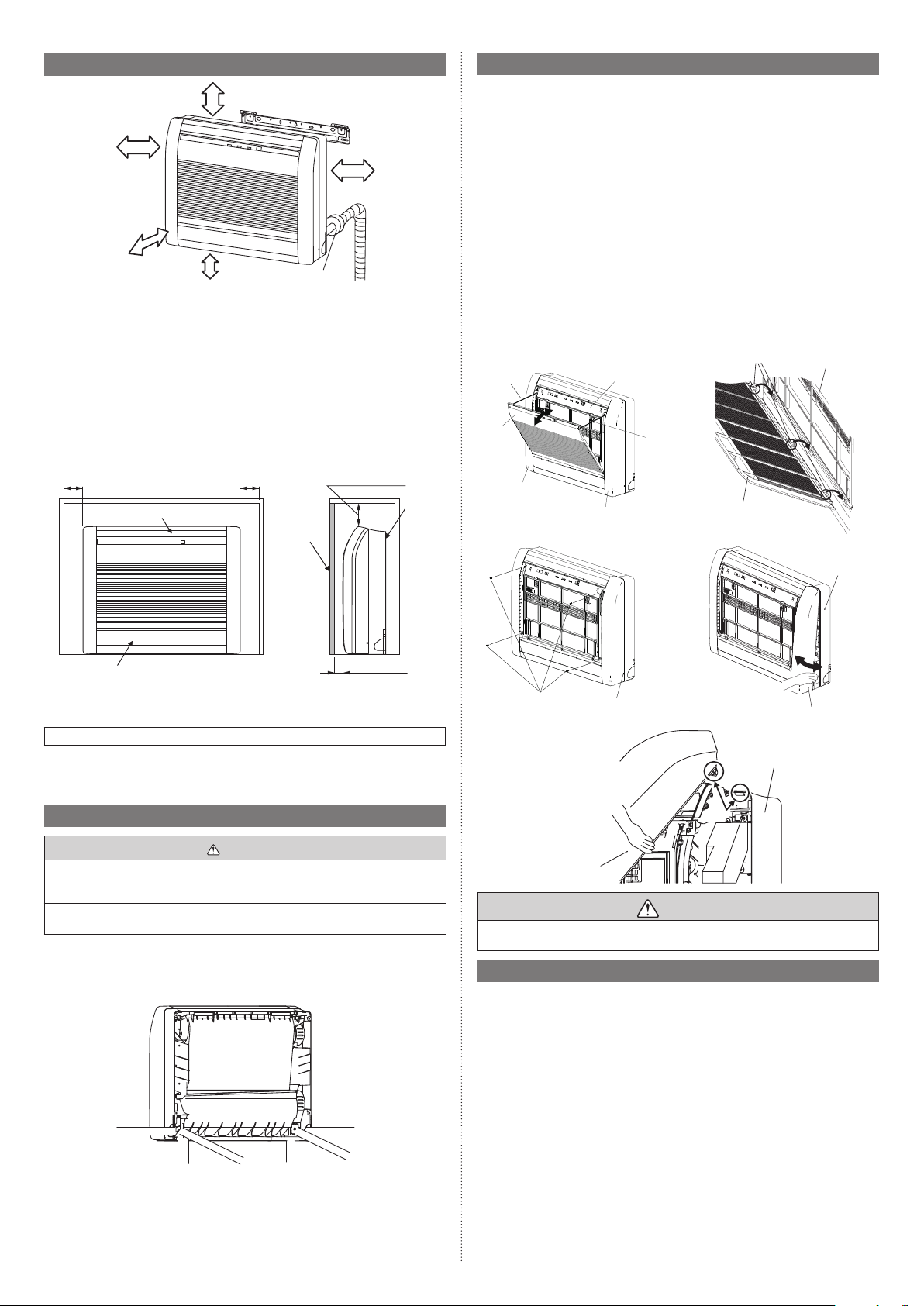
3.2. Installation dimension
(Wall cap)
(Unit: mm)
80 or more
100 or more
(Unit: mm)
Indoor
unit
100 or more
80 or more
50 or more
150 or below from the floor
Embedding the Indoor unit in a Wall
• When installing a grating, use a grating with narrow upper and lower horizontal bars
so that the airflow from the upper and lower air outlets does not contact the bars. If the
horizontal bars will block the lower air outlet, use a stand, etc., to adjust the height of the
indoor unit. If the upper or lower air outlet is blocked, the air conditioner will not be able
to cool or warm the room well.
• Do not block the receiver with the grating. Otherwise, the grating will interfere with the
remote controller signal and significantly reduce the distance and area (angle) from
which the signals can be received.
• Use a grating with vertical bars, etc., that has at least 75% open area. If the grating has
horizontal bars or if the open area is less than 75%, performance could be reduced.
• When the indoor unit is embedded in a wall (built-in), the time it takes for the room
temperature to reach the set temperature will increase.
80 or more 80 or more
Upper air outlet
Grating
3.4. Side panel L, R removal and installation
The intake grille removal
(1) Open the intake grille.
(2) Remove the rope.
(3) Lay down the intake grille, until the axle at the bottom of the intake grille is removed.
The intake grille installation
(1) The fixing axle of the intake grille is installed on the Panel.
(2) Lift the intake grille upward.
The side panel L, R removal
(1) Remove intake grille (Reference the intake grille removal.)
(2) Remove 4 screws.
(3) The middle finger is hung on the lower part as shown in the figure, and it pulls to the
front, pushing [►] mark, and bottom hooks (2 position) is removed from Base.
(4) The side panel is pulled to the front, raising the upper surface, and a side panel is
removed.
The side panel L, R installation
(1) Firstly, fit the top part of the side panel, and insert top and bottom hooks.
(2) 4 screws is attached.
(3) The intake grille is attached.
Rope
Intake
grille
Side panel L
Front panel
Side panel R
Rope
Mounting shaft
Intake grille
Front panel
Lower air outlet
When embedding the indoor unit in a wall, restrict the movement of the horizontal vane
for the upper air outlet so that it only operates horizontally. If this setting is not performed,
heat will build up in the wall and the room will not be cooled or warmed properly.
Please explain the vane setting of direction only horizontally to the customer.
20 to 30
HOW TO SETTING VANE
Perform the “FUNCTION SETTING” according to the installation condition using the
remote controller. Refer to “7.4. Function setting”.
3.3. Indoor unit piping direction
WARNING
Install the air conditioner in a location which can withstand a load of at least 5 times the
weight of the main unit and which will not amplify sound or vibration. If the installation
location is not strong enough, the indoor unit may fall and cause injuries.
If the job is done with the panel frame only, there is a risk that the unit will come loose.
Please take care.
• The piping can be connected in the 6 directions indicated by (A), (B), (C), (D), (E) and
(F) in the figure. When the piping is connected in direction (B) or (E), cut along the piping groove in the side of the base with a hacksaw.
• When connecting the piping in direction (C), (F) cut a notch in the thin wall at the front
bottom of the base.
(Rear)
Base
Screw
[►] mark
Side panel R
Side panel R
Base
CAUTION
Install the SIDE PANEL L, R and INTAKE GRILLE securely. If installation is imperfect,
the SIDE PANEL L, R or INTAKE GRILLE may fall off and cause injury.
3.5. Cutting the hole in the wall for the connecting piping
(1) Cut a 65 mm diameter hole in the wall at the position shown in the figure.
(2) Always align the center of the wall hole. If misaligned, water leakage will occur.
(3) Cut the wall pipe to match the wall thickness, stick it into the wall cap, fasten the cap
with vinyl tape, and stick the pipe through the hole. (The connection pipe is supplied
in the installation set.)
(4) For left piping and right piping, cut the hole a little lower so that drain water will flow
freely.
En-3
Right outlet
(B)
(C)
Right bottom
outlet
(A)
Right rear
outlet
(F)
Left bottom
outlet
Left outlet
(E)
(D)
Left rear
outlet
For RIGHT REAR or LEFT REAR piping
(The following figure is a front view of the indoor unit installation location.)
550
59
For LEFT REAR
piping
48
Ø65
Ø65
For RIGHT or LEFT piping
Unit: mm
59
For RIGHT
REAR piping
Unit: mm
WARNING
Fix the indoor unit with 4 screws surely. If improperly installed, might cause to injury due
to the toppling or falling.
Install the indoor unit at the place that has adequate strength. Install the indoor unit so
that the installed unit can withstand the weight of adult body weight.
If improperly installed, might cause accidental injury due to the toppling or falling.
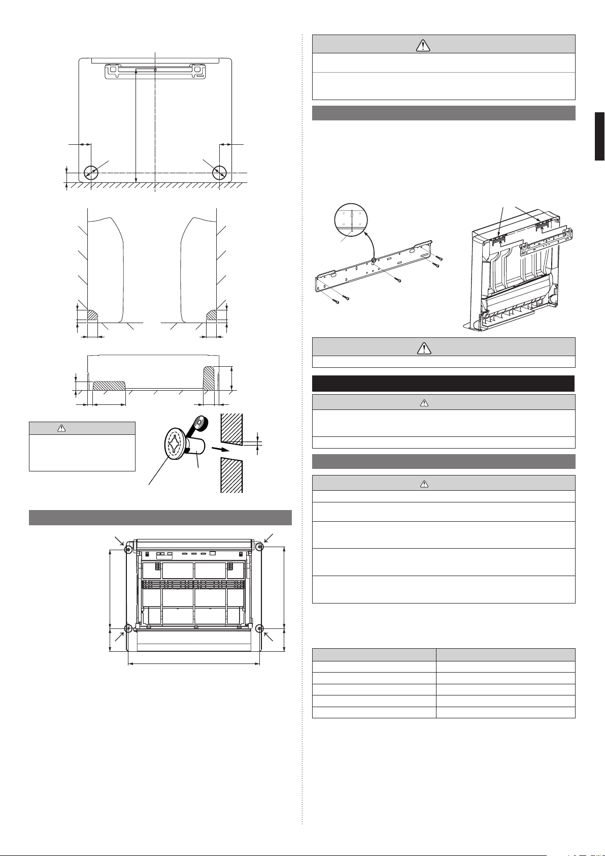
3.7. Installing the wall hook bracket
(1) Install the wall hook bracket so that it is correctly positioned horizontally and verti-
cally. If the wall hook bracket is tilted, water will drip to the floor.
(2) Install the wall hook bracket so that it is strong enough to support the weight of the
unit.
• Fasten the wall hook bracket to the wall with 5 or more screws through the holes near
the outer edge of the bracket.
• Check that there is no rattle at the wall hook bracket.
Hook the indoor unit to the
wall hook bracket (2 positions)
Leveling
method
Weight
For LEFT
piping
8165
54 54
For RIGHT BOTTOM or LEFT BOTTOM piping
For LEFT
BOTTOM
piping
Attach the wall pipe
If the wall pipe is not used, the
cable interconnecting the indoor
and outdoor units may touch
metal and cause electric leakage.
05
29
WARNING
Fasten with vinyl
tape
Wall cap*
3.6. Indoor unit installation
• Use the included and
fasten the indoor unit
at 4 locations (→)
each at top and the
middle of the unit.
• When the unit is set
to the wall, use the
wall hook bracket
and hook the top of
the indoor unit on the
indoor unit wall hook
bracket.
• Install it so that there
is no gap between
the indoor unit and
the wall.
124 423
For RIGHT
piping
8165
Unit: mm
For RIGHT
53
1
BOTTOM
piping
64182
29
5 to 10 mm
low
Wall pipe*
(Inside) Wall (Outside)
703
* Locally
purchased
Unit: mm
CAUTION
Install the wall hook bracket level, both horizontally and vertically.
4. PIPE INSTALLATION
Be more careful that foreign matter (oil, water, etc.) does not enter the piping than with
refrigerant R410A models. Also, when storing the piping, securely seal the openings by
pinching, taping, etc.
While welding the pipes, be sure to blow dry nitrogen gas through them.
4.1. Selecting the pipe material
Do not use existing pipes from another refrigeration system or refrigerant.
Use pipes that have clean external and internal sides without any contamination which
may cause trouble during use, such as sulfur, oxide, dust, cutting waste, oil, or water.
It is necessary to use seamless copper pipes.
Material : Phosphor deoxidized seamless copper pipes
It is desirable that the amount of residual oil is less than 40 mg/10 m.
Do not use copper pipes that have a collapsed, deformed, or discolored portion (especially on the interior surface). Otherwise, the expansion valve or capillary tube may
become blocked with contaminants.
Improper pipe selection will degrade performance. As an air conditioner using R410A
incurs pressure higher than when using conventional (R22) refrigerant, it is necessary to
choose adequate materials.
• Thicknesses of copper pipes used with R410A are as shown in the table.
• Never use copper pipes thinner than those indicated in the table even if they are available on the market.
124 438
Thicknesses of Annealed Copper Pipes (R410A)
Pipe outside diameter [mm (in)] Thickness [mm]
6.35 (1/4) 0.80
9.52 (3/8) 0.80
12.70 (1/2) 0.80
15.88 (5/8) 1.00
19.05 (3/4) 1.20
CAUTION
CAUTION
En-4
 Loading...