

Page 1
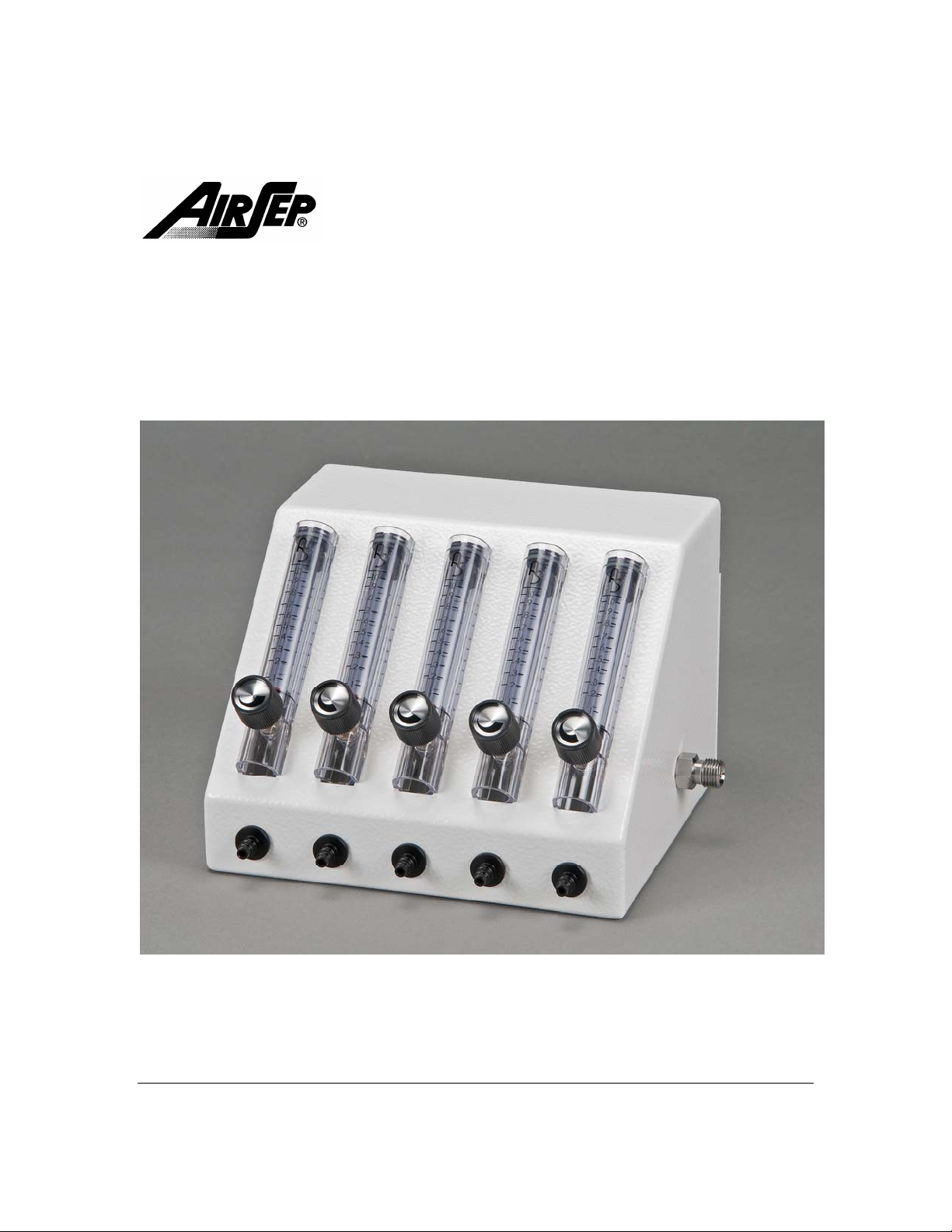
SureFlow™
Service Manual
AirSep Corporation 401 Creekside Drive Buffalo, New York 14228-2085 USA
Telephone: (716) 691-0202 24-Hour Fax (716) 691-4141 www.airsep.com
Page 2

Page 3

TABLE OF CONTENTS
Warnings, Cautions, Notes 1
Introduction 2
1.0 Flowmeter Replacement 3
1.9 Leak Testing 6
2.0 Inlet/Outlet Valve Replacement 7
2.6 Leak Testing 8
3.0 Specifications 9
4.0 Cleaning 9
5.0 Symbols 10
Page 4

Page 5
Warnings, Cautions, Notes
Refer to the instructions or manual from the oxygen source manufacturer for all
warnings, cautions and notes that may be applicable.
Oxygen promotes rapid burning. Do not allow smoking or open flames in the
same room where oxygen is being used.
If a SureFlow outlet is not in use, the flowmeter must be turned to 0.
The oxygen source must not exceed 50 psig (345 kPa)
1
Page 6

Introduction
SureFlow™ is a new and uniquely engineered flow station developed by AirSep Corporation for
economically administering medical-grade oxygen to multiple patients from an oxygen
concentrator or other oxygen source (gas or liquid).
This product enables clinicians and medics around the world to ma nage and redirect the flow
from a single oxygen source to a simple flow station to serve up to five individuals per SureFlow
unit.
Two or more SureFlow units can be connected together to serve even more individuals
simultaneously. Each flowmeter is adjusted separately to ensure precise control with a visual
indication of flow for safety and comfort.
Dual flow models of NewLife® Intensity 8 and 10 LPM concentrators provide greater flexibility in
delivering oxygen by allowing SureFlow to operate connected to one of the concentrator’s
flowmeters while the secondary flowmeter can supply oxygen for a nebulizer treatment or a
higher flow patient.
SureFlow units also meet the low flow oxygen needs of pediatric patients in a critical care nursery
in developing countries around the globe. The standard SureFlow is configured with 5 low flow
flowmeters, which display in 0.10 increments, and can be used in a wide range of settings from
0.10 to 1.0 LPM. SureFlow can also be specially ordered with a combination of 1 LPM and 5 LPM
flowmeters, or with five 2 LPM flowmeters which display in 1/8 LPM increments.
The SureFlow is a simple device that will not require a regular service schedule.
Two procedures, one for flowmeter replacement and one for inlet valve replacement, are included
in the unlikely event that a repair is needed. The flowmeter or inlet/outlet valve may need
replacement if it becomes damaged, or begins to leak.
2
Page 7

Disconnect from any oxygen source before attempting any service or
repair.
1.0 Flowmeter Replacement
1.1 With a Phillips head #2 screwdriver, remove the three screws in the back of the
device. Pull the bottom of the back cover out, then rotate up and away to remove the
cover.
Remove 3 screws,
then the rear cover
1.2 Cut the tubing to the inlet and the outlet of the flowmeter to be replaced.
Figure 1
Cut Tubing
Cut tubing between
the barb fitting and
the flowmeter inlet.
Figure 2
3
Page 8

1.3 Loosen and remove the pal nuts and retaining bracket that secure the flowmeter to
the cabinet. Remove the flowmeter.
Remove pal nut and
retaining bracket
Figure 3
1.4 Cut the heads off of the tie wraps that are on the two pieces of tubing that you
previously cut. Remove and discard this tubing.
Figure 4
Remove tie wraps
and tubing
4
Page 9

A
1.5 Assemble the 8.5 inch tube to the barb on the product outlet that you just removed
the old tubing from and install a tie-wrap behind the barb.
Figure 5
1.6 Assemble the 1 ¼ inch tube to the new flowmeter inlet valve and tie wrap behind the
barb.
New 8 1/2” tubing
ssemble 1 ¼” tube
to flow meter inlet
Figure 6
5
Page 10

1.7 Fit the new flowmeter into the desired slot. Assemble bracket and pal nut on the
flowmeter to secure the assembly to the cabinet housing.
Figure 7
1.8 Connect the 1-¼ inch tube from the flowmeter (inlet) to the barb on the tubing
assembly. Next, connect the 8.5” tube to the top of the flowmeter (outlet) and tie wrap
all connection points.
Figure 8
1.9 Leak Testing
After any servicing is complete, the SureFlow should be checked for leaks,
Attach to oxygen source and using soapy water or a leak test solution, check
all tubing connections before closing.
Another aid in determining the source of a leak(s) is to put your thumb over
each outlet at the SureFlow station, on at a time. The flowmeter ball must drop
to zero on each test, indicating no leak within the SureFlow.
1.10 Replace the back cover after leak testing, and use three screws to complete the
flowmeter replacement.
6
Page 11

Disconnect from any oxygen source before attempting any service or
repair.
2.0 Inlet/Outlet Valve Replacement
2.1 With a Phillips head #2 screwdriver, remove the three screws in the back of the
device. Pull the bottom of the back cover out then rotate up and away to remove the
cover.
Figure 9
2.2 Using two wrenches, hold the inner nut in place with one wrench (7/16 inch) and
unscrew the outer nut with the other wrench (5/8 inch).
Figure 10
Remove 3 screws,
then the rear cover
7
Page 12

2.3 Apply Teflon tape to the new inlet/outlet valve.
Figure 11
2.4 Using two wrenches hold the inner nut in place with one wrench (7/16 inch) and
screw in the outer nut of the valve with the other wrench (5/8 inch).
Figure 12
2.5 Leak Testing
After any servicing is complete, the SureFlow should be checked for leaks,
Attach to oxygen source and using soapy water or a leak test solution, check
all tubing connections before closing.
Another aid in determining the source of a leak(s) is to put your thumb over
each outlet at the SureFlow station, on at a time. The flowmeter ball must drop
to zero on each test, indicating no leak within the SureFlow.
2.6 Replace the back cover after leak testing, and use three screws to complete the
inlet/outlet valve replacement.
8
Page 13

3.0 Specifications
SureFlow
Weight
Shipping Weight
Dimensions
Maximum Inlet
Pressure
Flowmeter Accuracy
Operating
Temperature
Storage Temperature
4.0 Cleaning
Do not use abrasive powders or chemicals. Clean only the exterior of the
SureFlow unit, which can be disinfected with either a common chemical
disinfectant or a diluted solution* of household bleach (sodium hypochlorite
5.25%). To use effectively, mix a solution of 1:100 parts of bleach to water. Wear
eye and skin protection and allow the solution to remain on the surface for 10
minutes. After using the disinfecting solution, rinse with water and wipe dry.
Make sure unit is completely dry and then retest it before you return it to
inventory.
* The manufacturers of sodium hypochlorite products recommend various strengths of a
bleach solution for killing bacteria, etc., based on the type of germ to disinfect; however,
a generally recommended solution is ¾ cups (237 ml) of household bleach per gallon
(3.79 L) of water.
3.28 lb (1.49 kg)
5.6 lb (2.5 kg)
9.7 in. W x 5.8 in. H x 7.2 in. D
(24.6 cm W x 14.7cm H x 18.3cm D)
50 psig (345 kPa)
0-1 lpm Flowmeter ± 3% of Full Scale
0-2 lpm Flowmeter ± 5% of Full Scale
0-5 lpm Flowmeter ± 5% of Full Scale
5 - 40°C (40° - 104°F)
-5° - 60°C (30° - 140°F)
9
Page 14

5.0 Symbols
Symbols are frequently used on equipment in preference to words with the intention of lessening
any possibility of misunderstanding caused by language differences. Symbols can also permit
easier comprehension of a concept within a restricted space.
The following table is a list of symbols and definitions that may be used with AirSep’s SureFlow.
These symbols are referenced from the appropriate International Electro-technical Commission
(IEC) standards.
Symbol
No smoking
Description
Complies with the 93/42/EEC
directive drawn up by the
approved organization No. 0459
Use no oil or grease
Consult instructions for use
:WEEE Directive
Symbol
Description
Warning – Describes a hazard or
unsafe practice that if not avoided
can result in severe bodily injury,
death or property damage
Caution – Describes a hazard or
unsafe practice that if not avoided
can result in minor bodily injury or
property damage
Note – Provides information
important enough to emphasize
or repeat
Do not disassemble
Do not expose to open flames
10
Page 15

Page 16

MN155-1
Rev A
 Loading...