

AirSep Centrox PSA Technical manual

AirSep® Corporation
Centrox
PSA Oxygen Concentrator
Instruction Manual
MN124-1 04/10 Rev. -
AirSep® Corporation x 260 Creekside Drive x Buffalo, NY 14228-2075 USA
Phone: 1-800-320-0303 x Fax: (716) 691-1255 x www.airsep.com

Ownership Data
Take a moment to note important information below about your AirSep CENTROX PSA Oxygen
Concentrator. Keep this instruction manual, along with your invoice, to serve as a permanent
record of your purchase.
PSA Oxygen Concentrator
Model Number:
Serial Number:
Invoice Date:
Start-Up Date:
AirSep Representative
Company:
Contact:
Address:
CENTROX
City/Town: State: Zip:
Country: Fax:
Telephone: Telex:
Before you attempt to install, operate, or repair the oxygen concentrator,
read and thoroughly understand this instruction manual. Improper
operation can result in severe bodily injury, damage to the system, or
poor performance.


AirSep® Corporation
1.0 Introduction ..................................................................................... 1-1
1.1 General .............................................................................................1-1
1.2 Warnings, Cautions, and Notes ........................................................1-1
1.3 References to Controls and Indicators with Labels ..........................1-1
2.0 Safety................................................................................................ 2-1
2.1 General .............................................................................................2-1
2.2 Potential Hazards .............................................................................2-1
2.3 Safety Publications ........................................................................... 2-3
3.0 System Description ......................................................................... 3-1
3.1 Introduction .......................................................................................3-1
Table of Contents
4.0 Controls, Parts, and Connections.................................................. 4-1
4.1 Introduction .......................................................................................4-1
4.2 Oxygen Concentrator Controls and Indicators.................................. 4-1
4.3 Oxygen Concentrator Parts ..............................................................4-4
4.4 Auxiliary Kits Information (Optional) .................................................4-8
4.5 Connections....................................................................................4-10
5.0 Installation ....................................................................................... 5-1
5.1 Unpacking.........................................................................................5-1
5.2 Pre-Installation Guidelines................................................................5-3
5.3 Installation Instructions .....................................................................5-4
6.0 Operation ......................................................................................... 6-1
6.1 Initial Start-Up ...................................................................................6-1
6.2 Operation ..........................................................................................6-4
6.3 Shutdown..........................................................................................6-5
6.4 Normal Start-Up................................................................................6-5
6.5 Start-Up after an Extended Shutdown ..............................................6-5
CENTROX Instruction Manual i

AirSep® Corporation
7.0 Maintenance/Service .......................................................................7-1
7.1 Weekly Maintenance ........................................................................7-2
7.2 Semi-Annual Maintenance................................................................ 7-2
7.3 Annual Maintenance......................................................................... 7-4
7.4 Pressure Switch Adjustment Procedure ........................................... 7-5
8.0 Troubleshooting ..............................................................................8-1
Troubleshooting Chart.................................................................................. 8-2
A Appendix Technical Data ............................................................... A-1
B Appendix Warranty/Returns .......................................................... B-1
C Appendix Parts List ........................................................................ C-1
D Appendix Component Literature ................................................... D-1
ii CENTROX Instruction Manual

AirSep® Corporation
Figure 3.1: CENTROX Oxygen Concentrator ........................................... 3-1
Figure 4.1: Compressor Enclosure........................................................... 4-1
Figure 4.2: PSA Enclosure Controls and Indicators .............................. 4-2
Figure 4.3: Compressor Enclosure Internal Components ...................... 4-4
Figure 4.4: PSA Enclosure Internal Components.................................... 4-5
Figure 4.5: Oxygen Receiver ..................................................................... 4-9
Figure 5.1: General Arrangement of the CENTROX concentrator ......... 5-5
Figure 6.1: PSA Enclosure Supply Valve Assembly ............................... 6-4
List of Illustrations
Figure 7.1: Pressure Switch ...................................................................... 7-6
Figure A.1: Flow Schematic ..................................................................... A-5
Figure A.2: Wiring Schematic (120 V, 60 Hz) – PSA Enclosure............. A-6
Figure A.3: Wiring Schematic (220 V, 50 Hz) – PSA Enclosure............. A-7
Figure A.4: Wiring Schematic (120 V, 60 Hz) – Compressor Encl......... A-8
Figure A.5: Wiring Schematic (220 V, 50 Hz) – Compressor Encl......... A-9
CENTROX Instruction Manual iii

AirSep® Corporation
1.0 Introduction
1.1 General
This instruction manual provides a description of the AirSep CENTROX
Pressure Swing Adsorption (PSA) Oxygen Concentrator as well as
instructions for its installation, operation, and maintenance. Pertinent
drawings and component information are also included.
To ensure safe operation and proper system maintenance, AirSep
Corporation recommends that you keep this instruction manual readily
available for reference.
1.2 Warnings, Cautions, and Notes
As you read the instruction manual, pay special attention to the Warning,
Caution, and Note messages. They identify safety guidelines or other
important information as follows:
Provides information that can prevent severe bodily
injury or death.
Provides information that can prevent minor bodily
injury or property damage.
Provides information important enough to emphasize
or repeat.
1.3 References to Controls and Indicators with Labels
This operating manual uses uppercase characters (e.g., ON/OFF switch)
to refer to controls and indicators. Refer to section 4 for a description of
all the controls and indicators of the oxygen concentrator.
CENTROX Instruction Manual 1-1

AirSep® Corporation
yg
2.0 Safety
2.1 General
Oxygen, the most abundant of the elements, makes up about 50 percent
of the earth's crust. In its free state, it forms about one-fifth of our air by
volume. Although oxygen is classified as a non-flammable gas, it
supports combustion. As an active element, it combines directly or
indirectly with all elements except the rare gases. It is an invisible gas that
is colorless, odorless, and tasteless.
To ensure your safety, thoroughly read and familiarize yourself with this
Safety section. AirSep Corporation strongly recommends that you review
this section periodically.
2.2 Potential Hazards
Before you attempt to install, operate, or repair the CENTROX Oxygen
Concentrator, read and thoroughly understand this instruction manual.
Improper operation can result in severe bodily injury, damage to the
system, or poor performance.
It is recommended to have an alternate source of
oxygen supply if a power failure or equipment
malfunction occurs.
Take extreme care to keep all the oxygen piping and
vessel clean. To avoid a fire or an explosion, oxygen
clean all surfaces that can come in contact with oxygen.
Check all oxygen fittings/joints for leaks with an
ox
en-compatible leak-detecting solution.
CENTROX Instruction Manual 2-1
AirSep® Corporation
Oxygen vigorously accelerates the burning of
combustible materials. In an oxygen-enriched
atmosphere, many materials that do not burn in
normal air require only a slight spark or moderate
heat to set them aflame.
To avoid a fire or an explosion, keep gasoline,
kerosene, oil, grease, cotton fibers, paint, and any
other combustible material away from any part of the
CENTROX Oxygen Concentrator or optional auxiliary
oxygen receiver.
Do not smoke or use an open flame near the oxygen
concentrator or optional auxiliary oxygen receiver.
Post "NO SMOKING OR OPEN FLAMES" signs in
the area where the oxygen concentrator and optional
auxiliary oxygen receiver are located. AirSep
STRONGLY recommends that only individuals trained
and experienced in the safe handling of oxygen
operate this system.
The interior of the CENTROX Oxygen Concentrator
contains electrical parts that can produce an electrical
hazard if not handled properly. To prevent electrical
shock, read and thoroughly understand the
Troubleshooting section of this instruction manual
before you service the system.
Connect the oxygen concentrator power cord to a
properly grounded wall outlet on a circuit that cannot
be accidentally turned off. Do not use extension
cords.
To prevent fire or electrical shock, locate the oxygen
concentrator and the auxiliary oxygen receiver (if
supplied) indoors away from rain or any other type of
moisture.
2-2 CENTROX Instruction Manual

AirSep® Corporation
2.3 Safety Publications
Disconnect power before servicing oxygen generator.
This section is not a complete summary of required safety procedures.
Review the following publications for additional information on the safe
handling of oxygen:
"Installation of Bulk Oxygen Systems at Consumer Sites;" NFPA
No. 50; National Fire Protection Association; 1 Batterymarch
Park; P. O. Box 9101; Quincy, Massachusetts 02269-9101 USA.
"Oxygen;" Pamphlet G-4; Compressed Gas Association; 1725
Jefferson Davis Highway; Arlington, Virginia 22202-4102 USA.
"Cleaning Equipment For Oxygen Service," Pamphlet G-4.1;
Compressed Gas Association; 1725 Jefferson Davis Highway;
Arlington, Virginia 22202-4102 USA.
CENTROX Instruction Manual 2-3

AirSep® Corporation
3.0 System Description
3.1 Introduction
Air Contains 21 % oxygen, 78% nitrogen, 0.9% argon, and 0.1% other
gases. AirSep Oxygen Concentrator separates this small percentage of
the oxygen from the compressed air through a unique Pressure Swing
Adsorption (PSA) process.
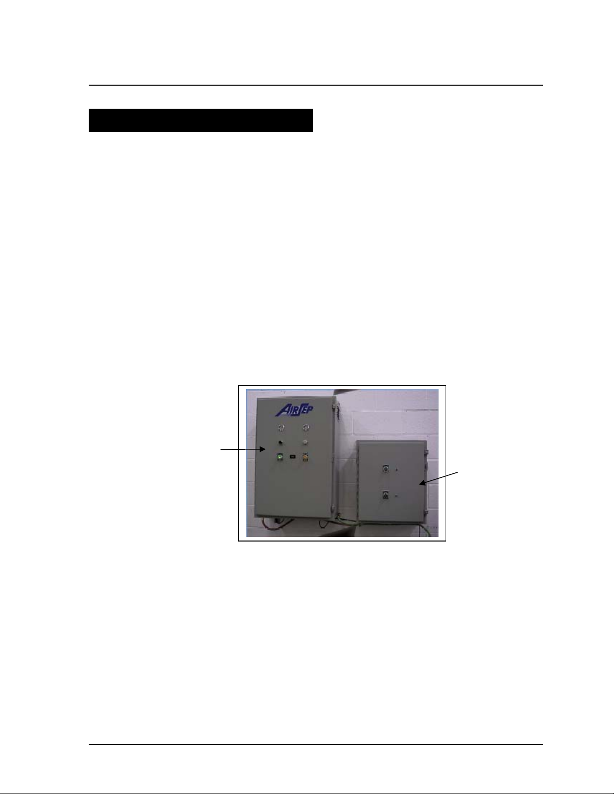
The CENTROX unit consists of two enclosures. The smaller enclosure
contains two compressors that supply air for the process. Each
compressor has a dedicated switch and circuit breaker. The cord from the
enclosure plugs into the PSA enclosure. This cord must not be plugged
into any other power supply outlet. Circuitry inside the PSA enclosure
controls the power supplied to the compressors. The power cord from the
PSA enclosure plugs into the wall. Figure 3.1 shows the two enclosures
of the CENTROX oxygen concentrator.
PSA Enclosure
The compressor enclosure (See Figure 3.1) supplies pressurized air to
the PSA enclosure (See Figure 3.1). Inside the PSA enclosure, the
pressurized air enters the feed & waste manifold (See Figure 4.4). A
series of valves in the feed & waste manifold controls the flow of air into
each of the adsorber beds (See Figure 4.4). Valves also connect the beds
to two mufflers (See Figure 4.4) that allow waste gas to be vented from
the beds. The oxygen concentrator uses in its adsorber vessels an inert
ceramic material called molecular sieve to separate compressed air into
the oxygen and the other gases. The unique properties of molecular sieve
allow it to attract, or adsorb, nitrogen physically from air under pressure.
Compressor
Figure 3.1: CENTROX Oxygen Concentrator
CENTROX Instruction Manual 3-1

AirSep® Corporation
This allows oxygen to exit the adsorbers as a product gas. Oxygen from
top of the beds then flows to the check valve assembly and then to the
product manifold (See Figure 4.4). The check valve assembly supplies
product oxygen to the flow controller. The product manifold controls the
flow of oxygen from one bed to another during various stages of the
oxygen generating process. The product oxygen then flows through the
product valve to the customer’s application. An oxygen analyzer
continuously monitors the purity of oxygen and provides an alarm in case
of low purity.
The entire oxygen generating process is completely regenerative, which
makes it both reliable and virtually maintenance-free. The molecular sieve
does not normally require replacement.
This instruction manual serves as the guidelines for CENTROX oxygen
concentrator. Refer to the illustrations, located in the Appendix A of this
instruction manual, for the detailed flow diagram and electrical schematic
of the oxygen concentrator referenced in this instruction manual.
3-2 CENTROX Instruction Manual
AirSep® Corporation
4.0 Controls, Parts, and Connections
4.1 Introduction
The section describes the various parts, controls, indicators and
connections required for the CENTROX oxygen concentrator.
4.2 Oxygen Concentrator Controls and Indicators
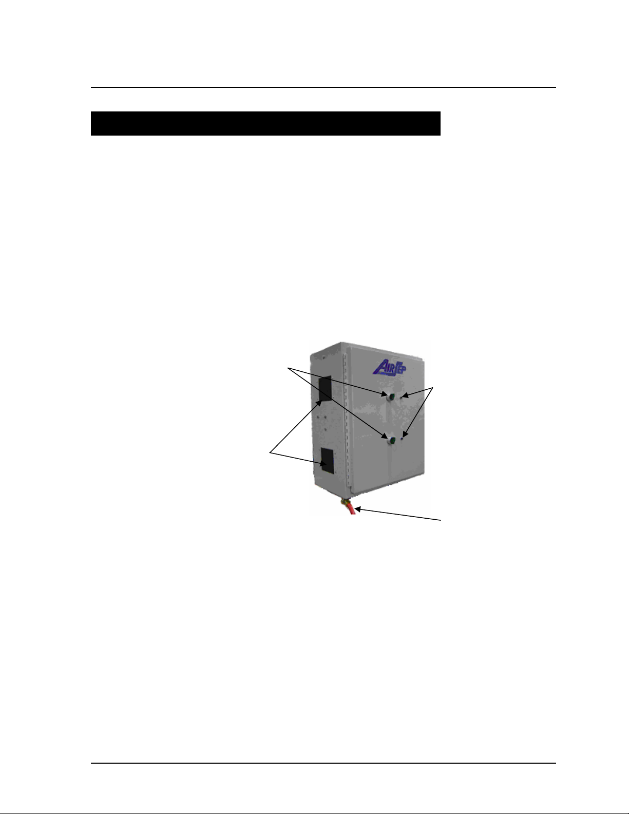
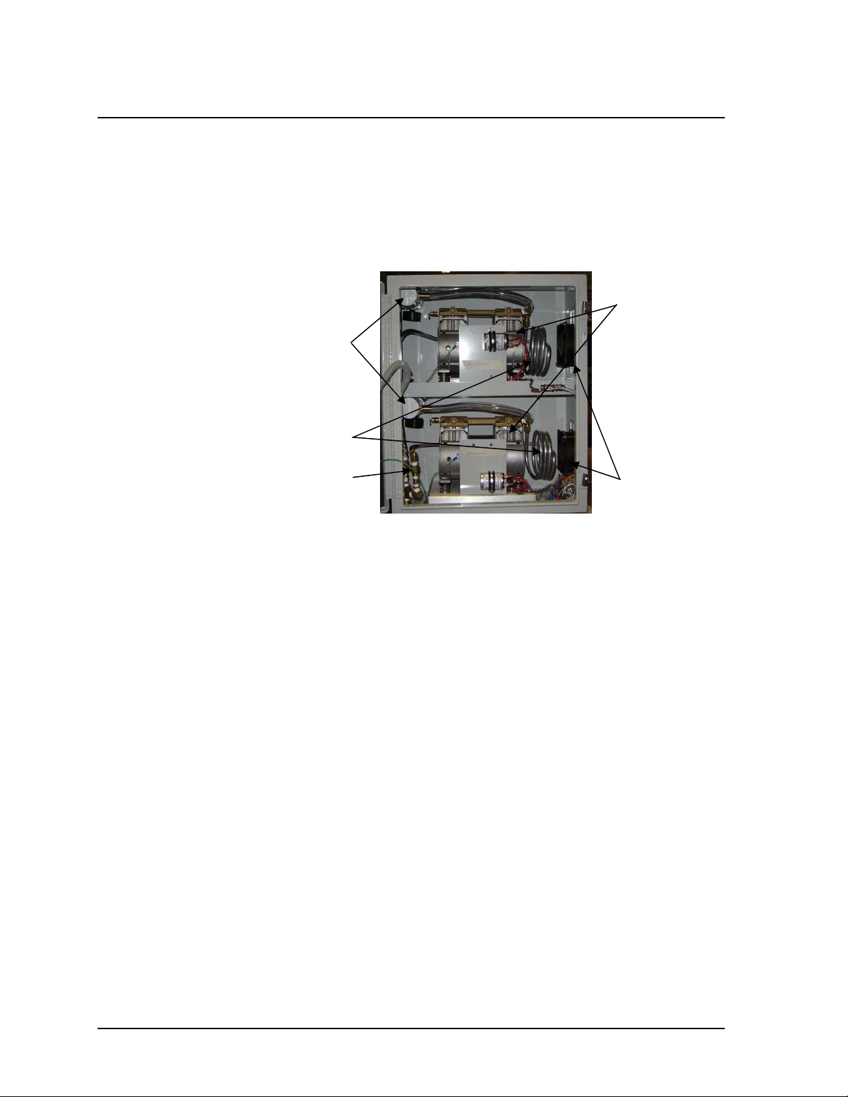
4.2.1 Compressor Enclosure
Figure 4.1 shows the compressor enclosure along with all the controls
and indicators.
On/Off
Circuit Breaker
Air Intake
Hose for
Compressed Air to
PSA Enclosure
Figure 4.1: Compressor Enclosure
ON/OFF (Power) Switch
The individual ON/OFF switches (green color) on the compressor
enclosure starts and stops the operation of the oxygen compressors.
When you supply power to the system, the green indicator light of the
switches turns on. It remains lit whether the switch is in the ON or
OFF position (See Figure 4.1).
Circuit Breaker Reset Buttons
The individual circuit breaker reset buttons on the compressor
enclosure are used to reset the compressors after an electrical
overload shutdown (See Figure 4.1).
CENTROX Instruction Manual 4-1
AirSep® Corporation
g
(
)
Air Intake Filters
Located on the left side panel, the air intake filter removes any foreign
particles from the air that enters the compressor enclosure (See
Figure 4.1).
Fuses/Circuit Breakers, if required, must be replaced
with the same type and amp rating as the original.
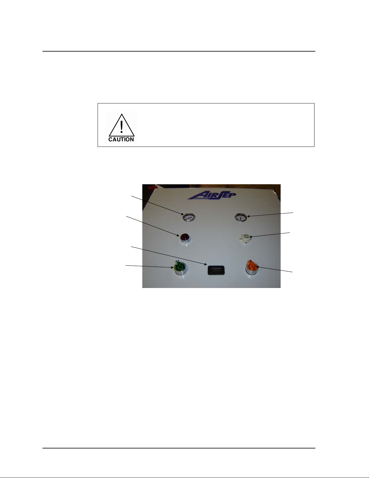
4.2.2 PSA Enclosure
Figure 4.2 shows the controls and indicators of the PSA enclosure.
Feed Air
Pressure Gauge
Low Purity
ht
Li
Hour Meter
Product
Pressure Gauge
Low Purity
Alarm
On/Off
Power
Figure 4.2: PSA Enclosure Controls and Indicators
Auto/Manual
Switch
ON/OFF (Power) Switch
The ON/OFF switch starts and stops the operation of the oxygen
concentrator. When you supply power to the system, the switch's
green indicator light turns on. It remains lit whether the switch is in the
ON or OFF position (See Figure 4.2).
AUTO/MANUAL Switch
The AUTO/MANUAL switch includes an yellow indicator light. In the
AUTO position, the concentrator cycles on and off to meet oxygen
demand. In the MANUAL position, the concentrator cycles
continuously. The concentrator produces oxygen only while the yellow
light is lit (See Figure 4.2).
Hour Meter
The hour meter indicates the total number of hours the concentrator
has cycled (See Figure 4.2).
4-2 CENTROX Instruction Manual
AirSep® Corporation
Low Purity Light
The unit is equipped with an oxygen sensor. If the purity supplied to
the tank is below 85 % (r 3%), the red light on the PSA enclosure will
be on (See Figure 4.2).
Low Purity Alarm
If the purity is below 85 % (r 3%) for more than 30 minutes, an
audible alarm will sound (See Figure 4.2).
The low oxygen purity alarm will sound for 4
seconds when the unit is turned on.
FEED AIR PRESSURE Gauge
The FEED AIR PRESSURE gauge indicates the pressure of the feed
air before it enters the PSA enclosure (See Figure 4.2).
PRODUCT PRESSURE Gauge
The PRODUCT PRESSURE gauge indicates the pressure of oxygen
coming out of the adsorber beds (See Figure 4.2).
CENTROX Instruction Manual 4-3
4.3 Oxygen Concentrator Parts
Figure 4.3 and Figure 4.4 shows the internal components of the CENTOX
oxygen concentrator
4.3.1 Compressor Enclosure
Resonators
Heat Exchanger
AirSep® Corporation
Compressors
Check Valve
Assembly
Figure 4.3: Compressor Enclosure Internal Components
Cabinet Fans
Compressors
The compressors compress the air entering the enclosure before it is
supplied to the PSA enclosure (See Figure 4.3).
Cabinet Fans
The cabinet fans provide internal cooling for the air compressor. Fans
also help in better circulation of the air inside the compressor
enclosure (See Figure 4.3).
Compressor Intake Filter
This filter provides additional filtration for the air as it enters the air
compressor. This filter is attached to the gray PVC pipe. The
complete assembly of the PVC pipe and the filter is called resonator
(See Figure 4.3).
Heat Exchanger
The heat exchanger coils cool the compressed air leaving the
compressor enclosure (See Figure 4.3).
Check Valve Assembly
Check Valve assembly prohibits the back flow of compressed air.
4-4 CENTROX Instruction Manual
AirSep® Corporation
r
r
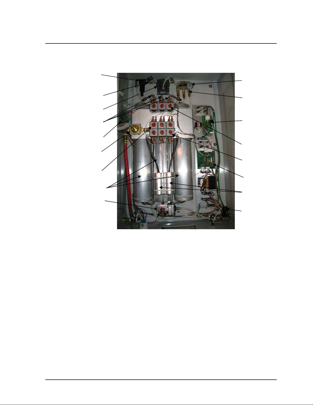
4.3.2 PSA Enclosure
Coalescing Filte
Product Valve
Flow Controlle
Product
Feed Air
Dump Valve
Check Valve
Feed Valves
Adsorber Beds
Pressure Switch
Product
Pressure Gauge
Check Valve
Assembly
Oxygen
Monitor
Board
Equalization
Waste Valves
Main Circuit
Exhaust
Mufflers
Oxygen
Sample
Regulator
Figure 4.4: PSA Enclosure Internal Components
Adsorber Beds
The adsorbers contain the molecular sieve that adsorbs (attracts)
nitrogen from compressed air and allows oxygen to pass through as
product gas (See Figure 4.4).
Main Circuit Board
Main circuit board provides signal to all the valves based on the status
of the oxygen generator.
Feed Air Dump Valve
The solenoid-operated valve is used to dump the compressed feed air
for 3-5 sec at the initial start-up and 1 sec at the start of standby
mode. This removes any pressure that builds up inside the
compressor to ensure easy start-up.
Check Valve
Check Valve assembly prohibits the back flow of compressed air.
CENTROX Instruction Manual 4-5

AirSep® Corporation
Feed Valves
The automatic feed air valves control the flow of the feed air as the air
enters the adsorbers (See Figure 4.4).
Waste Valves
The automatic waste valves control the flow of waste gas as it exits
the adsorbers (See Figure 4.4).
Exhaust Mufflers
The mufflers muffle the noise produced by the waste gas that vents
through the beds (See Figure 4.4).
Product Manifold
Product manifold facilitates the oxygen flow across adsorber beds
(from top of the adsorber beds) and to the product delivery line.
Equalization Valves
The equalization valves on the product manifold controls the flow of
oxygen from one bed to another during various steps of the oxygen
generation process (See Figure 4.4).
Check Valves Assembly
The check valve assembly supplies the product oxygen to the flow
controller. See Figure 4.4.
Product Pressure Gauge
Product pressure gauge mounted on the check valve assembly (See
Figure 4.4) displays the pressure of the product oxygen.
Flow Controller
The flow controller regulates the flow of oxygen (See Figure 4.4).
Product Valve
The valve prevents the supply of oxygen when the unit is in standby
mode (Refer to section 6 for the description of different types of
mode). See Figure 4.4 for the location of the product valve.
Coalescing Filter
The coalescing filter serves as bacteria filter and removes any
bacteria present in the oxygen supply (See Figure 4.4).
Oxygen Monitor Board
The oxygen sensor monitors the purity supplied from the PSA
enclosure. If the oxygen purity decreases below the set point, low
purity light on the PSA enclosure will be on. If the problem persists for
more than 30 minutes, a low purity alarm will sound.
4-6 CENTROX Instruction Manual

AirSep® Corporation
Oxygen Sample Regulator
A regulator before the oxygen monitor board regulates the pressure to
4-5 psig to the oxygen monitor board. Refer to the section 7 for the
regulator adjustment.
Pressure Switch
When the oxygen concentrator operates in Auto mode, the pressure
switch monitors the oxygen pressure at the outlet of the oxygen
concentrator. When the pressure at the oxygen concentrator outlet
increases to the pressure switch upper setpoint, the pressure switch
circuit closes and the oxygen concentrator starts a timed shutdown
that stops the unit at the end of the shutdown sequence (After 10
additional cycles). When the pressure at the oxygen concentrator
outlet decreases to the lower setpoint of the switch, the pressure
switch opens to activate the oxygen concentrator and the oxygen
production begins. When the oxygen concentrator operates in Manual
mode, the pressure switch circuit remains open and the oxygen
concentrator cycles continuously. Refer to the appendix A of the
manual for lower and upper setpoint settings of the pressure switch.
CENTROX Instruction Manual 4-7
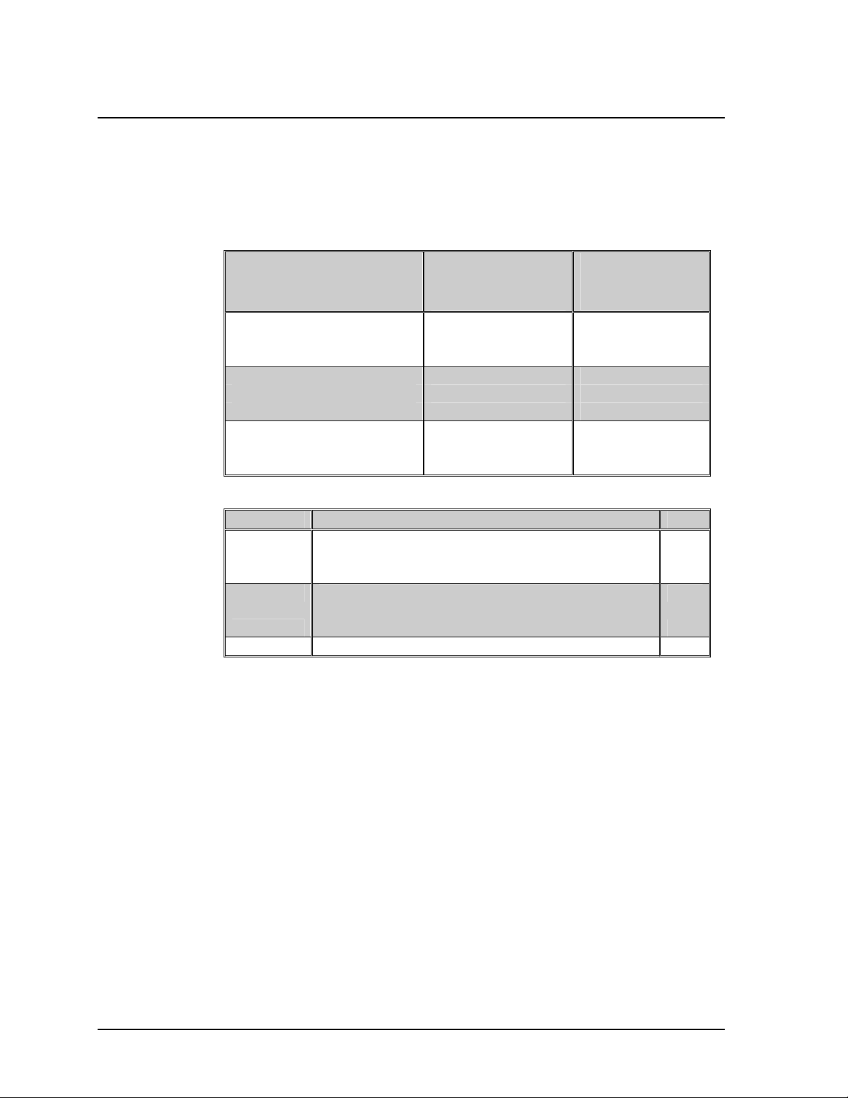
4.4 Auxiliary Kits Information (Optional)
The items discussed in this section are supplied as ordered. Listed below
are the different starter kits available as per the oxygen concentrator
ordered.
AirSep® Corporation
Unit # Kit #
(Customer
Supplied Tank)
AS074-1 120 VAC/60 Hz
AS074-2 220 VAC/50 Hz
AS074-3 220 VAC/60 Hz
KI046-1 KI046-1
TA150-1
Table 4.1: Optional Starter Kits for the Concentrator Purchased
Kit # Description
KI046-1
Primary/Secondary Ball Valve Assembly 1
Hose Assembly, Oxygen-clean, (Secondary
Hose) 1
KI470-1
Regulator-Flowmeter Assembly 1
Hose Assembly, Oxygen-clean (Main Oxygen
Outlet Hose) 1
TA150-1
60 Gallon Tank Assembly, O
Table 4.2: Description of the Parts included in the Starter Kits
KI470-1 KI470-1
KI046-1 KI046-1
KI470-1 KI470-1
KI046-1 KI046-1
KI470-1 KI470-1
Kit #
(AirSep
Supplied Tank)
TA150-1
TA150-1
Qty.
Cleaned 1
2
Please contact AirSep Corporation Sales representative for ordering the
starter kits. Below is a brief description of item included in the starter kits.
Primary Oxygen Ball Valve
The primary oxygen ball valve controls the flow of oxygen from the
oxygen concentrator to your oxygen distribution system. See Figure 5.1.
Secondary Oxygen Ball Valve
The secondary oxygen ball valve controls the flow of a backup source of
oxygen to your oxygen distribution system. This ball valve should always
be closed unless a backup source is connected to it. See Figure 5.1.
Regulator-Flowmeter Assembly
This assembly consists of a pressure regulator and a flowmeter. The
pressure regulator attaches to the outlet port of the oxygen receiver to
regulate the pressure of the oxygen. The flowmeter is used to regulate
4-8 CENTROX Instruction Manual
AirSep® Corporation
the flow of the oxygen at the outlet of the oxygen receiver. Refer to figure
5.1 for the installation location of this assembly.
Oxygen Isolation Ball Valve Assembly
The oxygen isolation ball valve stops the flow of oxygen to the oxygen
receiver during troubleshooting. The oxygen relief valve in the assembly
prevents excess pressure from building in the oxygen receiver if a system
malfunction occurs. This assembly is shipped mounted on the oxygen
receiver. See Figure 4.5.
Main Oxygen Hose
An oxygen-clean hose is provided that connects the outlet of the supply
valve assembly (Refer to section 4.5) on the oxygen concentrator to the
oxygen isolation ball valve assembly on the oxygen receiver.
Secondary Oxygen Hose
Secondary hose is provided to connect the outlet of the regulatorflowmeter assembly to the inlet of the primary oxygen ball valve. Refer to
Figure 5.1.
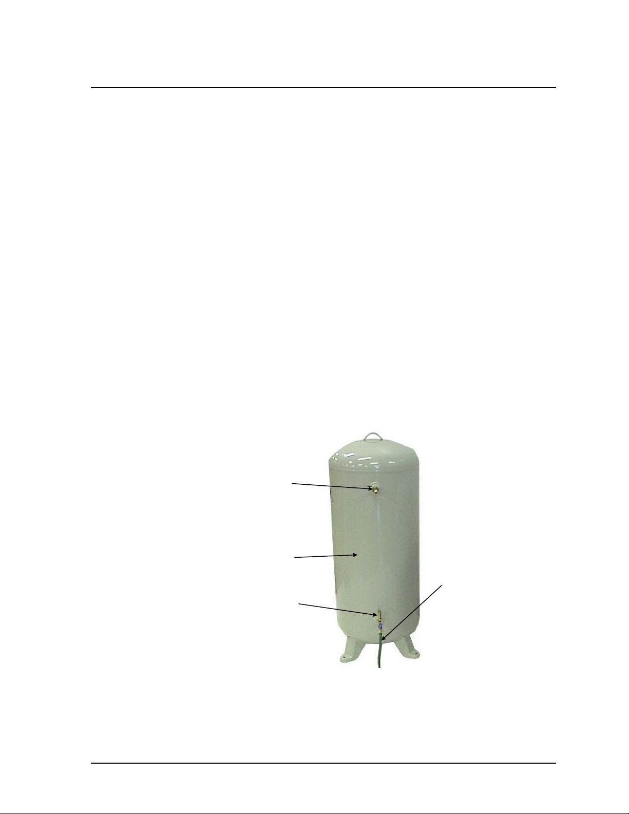
Oxygen Receiver
The oxygen receiver stores oxygen produced by the oxygen concentrator.
It also provides stable flow and purity for short-term surges of oxygen that
exceed the rated capacity of the oxygen concentrator.
Oxygen Outlet
Port
Oxygen
Receiver
Main Oxygen
Oxygen Isolation Ball
Valve Assembly
Hose
Figure 4.5: Oxygen Receiver
CENTROX Instruction Manual 4-9

4.5 Connections
Supply Valve Assembly
This assembly is shipped loose and must be connected to the PSA
enclosure oxygen outlet. The supply valve assembly limits the amount of
flow to the oxygen receiver during purge. Refer to Figure 5.1 and 6.1.
Power Cord
This power cord and its grounded electrical plug supply power to the
CENTROX when connected to a grounded electrical outlet.
AirSep® Corporation
4-10 CENTROX Instruction Manual
AirSep® Corporation
5.0 Installation
5.1 Unpacking
AirSep Corporation ships CENTROX Oxygen Concentrators on a wooden
skid covered with corrugated cardboard. This container includes an
accessory kit with an instruction manual and all the items necessary to
properly install the oxygen concentrator. The oxygen receiver (if supplied)
is shipped separately. Contact your AirSep Corporation’s Sales
representative for ordering the auxiliary kits supplied with the CENTROX
oxygen concentrator.
AirSep recommends that you follow these unpacking guidelines carefully
to protect yourself against loss from any damage caused during
shipment.
1. Inspect the exterior for damage. If you observe any damage, note it
on the freight bill or the express receipt before you sign it.
Failure to note exterior damage on the freight bill or
the express receipt at the time of delivery can result in
the carrier's refusal of a damage claim.
2. Carefully cut and remove any banding straps from the container. Then
remove the corrugated cardboard.
Remove the corrugated cardboard very carefully. You
may need to return the oxygen concentrator if it was
damaged during shipment
3. Remove the oxygen concentrator from the wooden skid.
4. Thoroughly inspect the oxygen concentrator interior and exterior for
damage caused during shipment. Pay special attention to the cabinet
switches, gauges, brackets, etc.
5. Remove the accessory kit and inspect the contents for damage.
6. Although the CENTROX is carefully inspected, tested, and packed, it
can be damaged during shipment due to improper handling. If you find
any concealed damage (loss or damage not found until the
CENTROX Instruction Manual 5-1
AirSep® Corporation
concentrator is unpacked), immediately call the delivery carrier and
file a concealed-damage claim. Keep ALL container material and
interior packing for the carrier's inspection.
YOU MUST MAKE A CONCEALED-DAMAGE CLAIM
WITHIN 24 HOURS OF DELIVERY. Only the
consignee can file this claim.
Follow these unpacking guidelines carefully to protect
yourself against loss from any damage caused during
shipment.
5-2 CENTROX Instruction Manual
AirSep® Corporation
5.2 Pre-Installation Guidelines
Before you install the CENTROX oxygen concentrator, and the oxygen
receiver, if supplied, refer to the Specifications section in the Appendix of
this instruction manual to determine the applicable space, and the power
requirements for your particular model.
A backup source of oxygen must be available if a
power failure or system malfunction occurs.
Make sure the area that surrounds the oxygen
concentrator is well ventilated, and provide sufficient
space around the unit [at least three feet] to allow for
cool air flow as well as to allow safe operation and
maintenance.
Locate the oxygen concentrator in an area where the
ambient air temperature remains between 4
and 44
under the AirSep Corporation Product Warranty.
Connect the oxygen concentrator power cord only to
a properly grounded electrical outlet on a circuit that
cannot be accidentally turned off. Do not use
extension cords.
Provide proper voltage to the oxygen concentrator to
prevent damage not covered under the AirSep
Product Warranty.
Do not plug in the power cord until you complete the
installation of the oxygen concentrator.
qC (112qF) to prevent damage not covered
qC (40qF)
CENTROX Instruction Manual 5-3
p
5.3 Installation Instructions
To assure proper installation and safe operation of your CENTROX PSA
Oxygen Concentrator, AirSep Corporation recommends that you review
this entire section before you attempt to install the unit.
Do not turn off power to any component unless you
are sure the medical facility does not require any
oxygen, or there is a sufficient alternative/backup
source of oxygen.
Before you attempt to install, operate, or repair the
oxygen concentrator, read and thoroughly understand
this instruction manual. Improper operation can result
in severe bodily injury, damage to the system, or poor
erformance.
AirSep® Corporation
Refer to the Figure 5.1 as you follow the installation instructions:
1. Place the oxygen concentrator near the inlet of your oxygen
distribution system.
2. Mount both the enclosures securely to a wall, ensuring that there is a
minimum of two feet between the two enclosures and minimum of
three feet between the compressor enclosure and a wall. The
compressor enclosure can be on either side of the PSA enclosure.
3. Open the compressor enclosure and remove the tie wrap from each
compressor. The tie wrap holds the compressor to a bracket support
for shipping purpose.
4. Attach the red air hose from the compressor enclosure to the fitting on
the left hand side of the PSA enclosure (See Figure 4.5 and 5.1).
The supply valve assembly at the outlet of the oxygen
concentrator has a small hole drilled in it and allows a
controlled amount of flow during purging process (See
Section 6) of the 60 gallon tank (If supplied).
5. Mount the supply valve assembly (shipped loose) at the outlet of the
PSA enclosure. Refer to Figure 5.1 and 6.1.
6. Attach the main oxygen hose from the supply valve to the inlet of the
oxygen isolation ball valve assembly at the oxygen tank (See Figure
4.5 and 5.1).
5-4 CENTROX Instruction Manual
 Loading...