

Page 1

AirSep® Corporation
PSA Oxygen Generator
Models AS-20–1000
Instruction Manual
MN011-1 A12/02
Suggested List Price $75.00 (U.S.D.)
AirSep® Corporation • 260 Creekside Drive • Buffalo, NY 14228-2075 USA
Phone: (716) 691-0202 • Fax: (716) 691-1255
Page 2

Page 3
Ownership Data
Please take a moment to note below important information about your AirSep® Corporation
PSA Oxygen Generator. Retain this instruction manual, along with your invoice, to serve as
a permanent record of your purchase.
PSA Oxygen Generator
Model Number:
Serial Number:
Invoice Date:
Start-up Date:
AirSep Representative
Company:
Contact:
Address:
City/Town: State: Zip:
Country: Fax:
Phone: Telex:
Before you attempt to install, operate, or repair the oxygen generator,
read and thoroughly understand this instruction manual. Improper
operation can result in severe bodily injury, damage to the oxygen
generator, or poor performance.
Page 4

Page 5

AirSep® Corporation 12/02
Table of Contents
1.0 Introduction ..................................................................................... 1-1
1.1 General .............................................................................................1-1
1.2 Warnings, Cautions, and Notes ........................................................1-1
1.3 Symbols ............................................................................................1-2
1.4 References to Controls and Indicators with Tags or Labels ............. 1-2
2.0
Safety................................................................................................ 2-1
2.1 General .............................................................................................2-1
2.2 Potential Hazards .............................................................................2-1
2.3 Safety Publications ...........................................................................2-3
3.0
Plant Description............................................................................. 3-1
3.1 General .............................................................................................3-1
4.0
Component Descriptions................................................................ 4-1
4.1 External Components ....................................................................... 4-1
4.1.1 Adsorbers 4-2
4.1.2 Enclosure 4-2
4.1.3 Control Panel 4-2
4.1.4 Connections 4-3
4.2 Manifold Components.......................................................................4-4
5.0
Installation ....................................................................................... 5-1
5.1 Handling and Unpacking...................................................................5-1
5.2 Pre-installation Guidelines ................................................................5-2
5.3 Installation Instructions .....................................................................5-3
6.0
Operation ......................................................................................... 6-1
6.1 Initial Start-up....................................................................................6-1
6.2 Operation ..........................................................................................6-3
6.3 Shutdown..........................................................................................6-3
6.4 Normal Start-up ................................................................................6-4
AS-20—1000 Instruction Manual table of contents - i
Page 6

04/02 AirSep® Corporation
6.5 Extended Shutdown..........................................................................6-4
6.6 Start-up after an Extended Shutdown............................................... 6-4
7.0
Maintenance..................................................................................... 7-1
7.1 Daily Monitoring ................................................................................7-1
7.2 Monthly Monitoring ...........................................................................7-1
7.3 Removing the Front Cover of the Enclosure (Not available on AS-450
— AS-1000 models) .....................................................................................7-2
7.4 Depressurizing the Filters .................................................................7-3
7.5 Changing Filter Elements .................................................................7-4
7.6 Depressurizing the Oxygen Generator ............................................. 7-5
7.7 Adjusting the Feed Air Regulator......................................................7-6
7.8 Adjusting the Pressure Switch ..........................................................7-6
8.0
Troubleshooting .............................................................................. 8-1
A
Appendix Technical Data............................................................... A-1
Specifications .............................................................................................. A-1
Operating Data ............................................................................................ A-9
Drawings.................................................................................................... A-10
Appendix Warranty/Returns .......................................................... B-1
B
Product Warranty......................................................................................... B-1
Limits of Liability .......................................................................................... B-2
Returning the Oxygen Generator or a Component for Service ................... B-2
C
Appendix Parts List........................................................................ C-1
AS-20 Parts ................................................................................................. C-2
AS-45 Parts ................................................................................................. C-3
AS-80 Parts ................................................................................................. C-4
AS-160 Parts ............................................................................................... C-5
AS-250 Parts ............................................................................................... C-6
AS-450 Parts ............................................................................................... C-7
AS-750 Parts ............................................................................................... C-8
AS-1000 Parts ............................................................................................. C-9
table of contents - ii AS-20—1000 Instruction Manual
Page 7

AirSep® Corporation 12/02
List of Illustrations
Figure 4-1 External Components — Front View ...................................... 4-1
Figure 4-2 Control Panel — AS-45 and AS-80 Models
Figure 4-3 Manifold Components — AS-160 and AS-250 Models
Figure 4-4 Manifold Components — AS-750 Model
Figure 5-1 Typical Installation Arrangement............................................ 5-3
Figure 5-2 120 Gallon Oxygen Receiver
Figure 7-1 Interior View of AS-45 and AS-80 Models
Figure 1 General Arrangement Drawing – AS-20
Figure 2 Flow Schematic – AS-20
Figure 3 Electrical Schematic – AS-20 (120V)
Figure 4 Electrical Schematic – AS-20 (220V)
Figure 5 General Arrangement Drawing – AS-45
Figure 6 General Arrangement Drawing – AS-80
......................................................... A-12
................................................... 5-5
...................................... A-13
...................................... A-13
............................ 4-3
.......... 4-4
................................ 4-5
............................. 7-3
................................ A-11
................................ A-14
................................ A-15
Figure 7 General Arrangement Drawing – AS-160
Figure 8 General Arrangement Drawing – AS-250 .............................. A-17
Figure 9 Flow Diagram – AS-45 through AS-250
Figure 10 Electrical Diagram – AS-45 through AS-250 (120V)
Figure 11 Electrical Diagram – AS-45 through AS-250 (220V)
Figure 12 General Arrangement Drawing – AS-450
Figure 13 General Arrangement Drawing – AS-750 ............................ A-21
Figure 14 Flow Diagram – AS-450 through AS-750
Figure 15 Electrical Schematic – AS-450 through AS-750 (120V) ...... A-23
AS-20—1000 Instruction Manual list of illustrations - i
.............................. A-16
................................. A-18
............ A-19
............ A-19
............................ A-20
............................. A-22
Page 8

04/02 AirSep® Corporation
Figure 16 Electrical Schematic – AS-450 through AS-750 (220V) ...... A-23
Figure 17 General Arrangement Drawing– AS-1000
Figure 18 Electrical Schematic – AS-1000 (120V)
Figure 19 Electrical Schematic – AS-1000 (220V)
Figure 20 Flow Diagram – AS-1000
........................................................ A-26
................................. A-25
................................. A-25
............................ A-24
ii - list of illustrations AS-20—1000 Instruction Manual
Page 9
AirSep® Corporation 12/02
1.0 Introduction
1.1 General
This instruction manual provides descriptions of the AirSep Corporation PSA
Oxygen Generator Models AS-20, AS-45, AS-80, AS-160, AS-250, AS-450, AS750, and AS-1000, as well as instructions for their installation, operation, and
maintenance. The Appendix of this instruction manual also includes pertinent
drawings and component literature.
To ensure safe operation and proper maintenance of the oxygen generator, AirSep
Corporation recommends that you keep this instruction manual readily available for
reference.
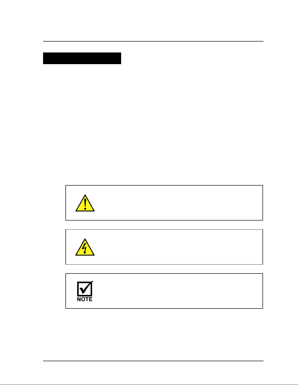
1.2 Warnings, Cautions, and Notes
As you read this instruction manual, pay special attention to the WARNING,
CAUTION, and NOTE messages. They identify safety guidelines or other important
information as follows:
Provides information that can prevent severe bodily injury or
death.
Cautions against the risk of electric shock.
Provides information important enough to emphasize or repeat.
AS-20—1000 Instruction Manual 1-1
Page 10
12/02 AirSep® Corporation
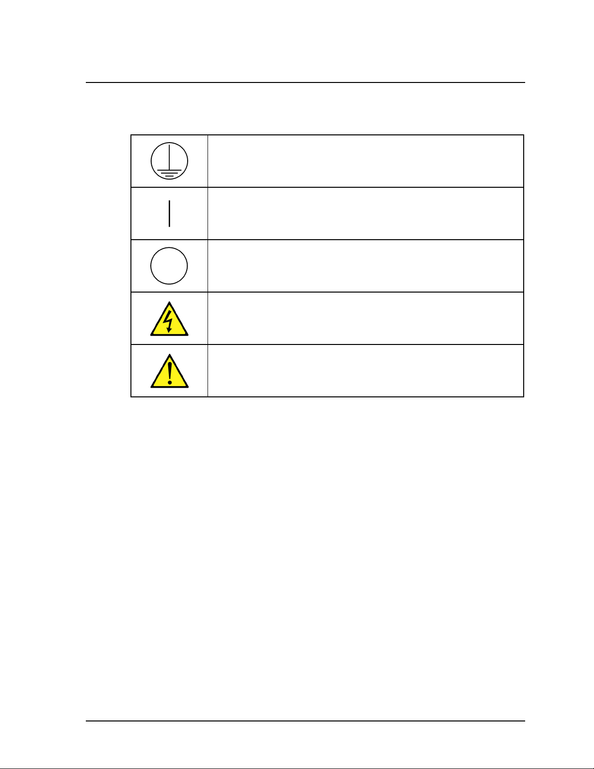
1.3 Symbols
IEC 417, No. 5019 Protective conductor terminal
IEC 417, No. 5007 On (supply)
IEC 417, No. 5008 Off (supply)
ISO 3864, No. B.3.6 Caution, risk of electric shock
ISO 3864, No. B.3.1 Caution (refer to accompanying
documents)
1.4 References to Controls and Indicators with Tags or Labels
This instruction manual uses uppercase characters (e.g., ON/OFF switch) to refer
to controls and indicators identified by tags or labels. Numbers inside parentheses
(e.g., V-2) identify manually operated flow controls (e.g., manual valves). Refer to
Chapter 4 for a description of the oxygen generator components.
1-2 AS-20—1000 Instruction Manual
Page 11
AirSep® Corporation 12/02
2.0 Safety
2.1 General
Oxygen, the most abundant of the elements, makes up approximately 50 percent
of the earth’s crust. In its free state, oxygen forms approximately one-fifth of our air by
volume. Although classified as a non-flammable gas, oxygen supports combustion.
As an active element, it combines directly or indirectly with all elements except the
rare gases. Oxygen is an invisible gas that is colorless, odorless, and tasteless.
To ensure your safety, thoroughly read and familiarize yourself with this entire
section of this instruction manual. In addition, AirSep Corporation strongly
recommends that you review this section periodically.
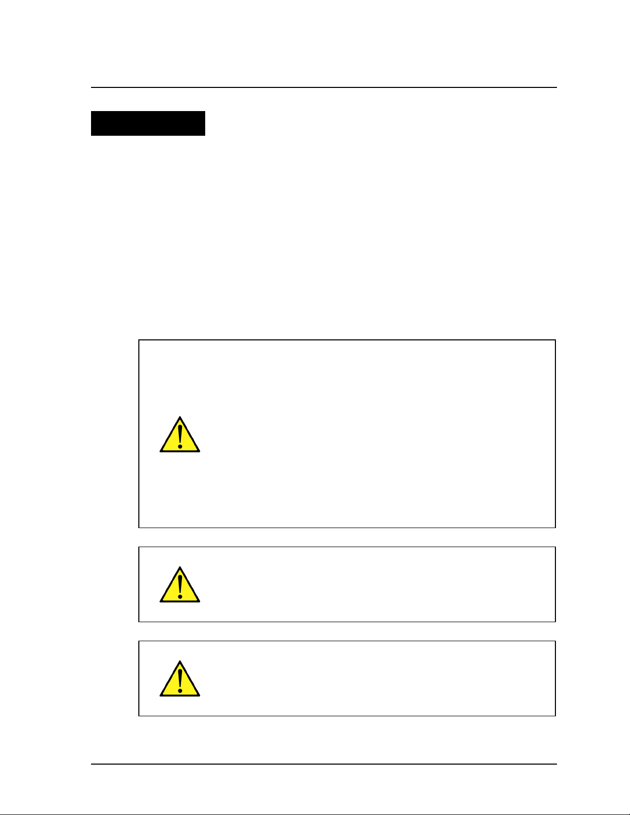
2.2 Potential Hazards
Oxygen vigorously accelerates the burning of combustible
materials. In an oxygen-enriched atmosphere, many materials
that do not burn in normal air require only a slight spark or
moderate heat to set them aflame.
To reduce the risk of fire or explosion, keep gasoline, kerosene,
oil, grease, cotton fibers, wood, paint, and other combustible
material away from all parts of the oxygen generator.
Do not allow smoking, open flame, or usage of electronic
devices that may generate sparks (e.g., cellular telephones)
within 15 m (50 feet) of any part of the oxygen generator.
Post “NO SMOKING OR OPEN FLAMES” signs conspicuously
near the location of the oxygen generator.
Take extreme care to keep all oxygen piping and vessels clean.
To avoid fire or explosion, oxygen clean all surfaces that can
come in contact with the product oxygen. Check all oxygen fittings
for leaks with an oxygen-compatible, leak-detecting solution.
To prevent fire or electrical shock, locate the oxygen generator
indoors, away from rain or any other type of moisture.
AS-20—1000 Instruction Manual 2-1
Page 12
12/02 AirSep® Corporation
Before you attempt to install, operate, or repair the oxygen
generator, read and thoroughly understand this instruction
manual and the component manuals located in Appendix D of
this instruction manual. Improper installation, operation, or
repairs can result in severe bodily injury, damage to the oxygen
generator, or poor performance.
The interior of the oxygen generator control cabinet contains
electrical parts that can produce an electrical shock hazard if
not handled properly. To prevent electrical shock, read and
thoroughly understand Section 8 — Troubleshooting in this
instruction manual before you service the oxygen generator.
AirSep oxygen generators are sold for use in industrial
applications only. Contact AirSep Corporation or an authorized
AirSep representative before you use this unit for any medical
application.
Disconnect power before servicing oxygen generator.
Do not disconnect protective earth:
2-2 AS-20—1000 Instruction Manual
Page 13

AirSep® Corporation 12/02
2.3 Safety Publications
The safety section of this instruction manual is not a complete summary of
required safety precautions. Review the following publications for additional
information on the safe handling of oxygen:
“Standard for Bulk Oxygen Systems at Consumer Sites;” NFPA No. 50; National
Fire Protection Association; 1 Batterymarch Park; P.O. Box 9101; Quincy,
Massachusetts 02269-9101 USA.
“Oxygen;” Pamphlet G-4; Compressed Gas Association; 1725 Jefferson Davis
Highway; Arlington, Virginia 22202-4102 USA.
“Cleaning Equipment for Oxygen Service;” Pamphlet G-4.1; Compressed Gas
Association; 1725 Jefferson Davis Highway; Arlington, Virginia 22202-4102
USA.
AS-20—1000 Instruction Manual 2-3
Page 14

Page 15

AirSep® Corporation 12/02
3.0 Plant Description
3.1 General
The AirSep Corporation PSA Oxygen Generator is a self-contained unit that utilizes
Pressure Swing Adsorption (PSA) technology to produce oxygen on site. The
oxygen generator uses compressed air as a feed gas to produce oxygen. The
compressed air flows through a filter assembly before the air enters the adsorber
vessels. A particulate filter removes condensed water, oil, dirt, scale, etc. from the
feed air, then in most models, a separate coalescing filter removes additional oil
and water vapor.
The oxygen generator uses in its adsorber vessels an inert ceramic material called
molecular sieve to separate compressed air into oxygen and other gases. The
unique properties of molecular sieve allow it to attract, or adsorb, nitrogen
physically from air under pressure. This allows oxygen to exit the adsorbers as a
product gas. The process valves on the oxygen generator then direct the oxygen to
the oxygen receiver for storage until needed by your application.
While one adsorber produces oxygen, the other depressurizes to exhaust the
waste gases it adsorbed (collected) during the oxygen production cycle. The entire
oxygen generating process is completely regenerative, which makes it both reliable
and virtually maintenance-free. The molecular sieve does not normally require
replacement when maintained and used according to this instruction manual.
Refer to the illustrations, located in Appendix A of this instruction manual, for a
detailed flow diagram, an electrical schematic, and general arrangement drawings
of all oxygen generator models referenced in this instruction manual as well as
typical cycle sequences and operating pressure levels.
AS-20—1000 Instruction Manual 3-1
Page 16

Page 17
AirSep® Corporation 12/02
A
4.0 Component Descriptions
The drawings in this section illustrate the location of the main components of the
various oxygen generator models. All models include similar components unless
noted otherwise; however, the location and size of these components varies
among the different models. Refer to Appendix A of this instruction manual for
general layout drawings and specifications for all oxygen generator models
referenced in this instruction manual. In addition, the oxygen generator requires use
of an oxygen receiver to provide stable flow and purity for short-term surges of feed
oxygen above the rated capacity of the oxygen generator.
4.1 External Components
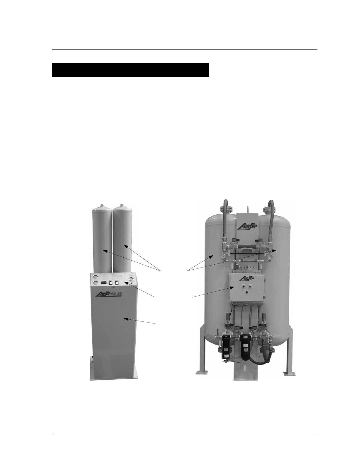
Figure 4-1 below illustrates on two models the external components viewed from
the front of the oxygen generator.
dsorbers
Control Panel
Enclosure
AS-45 Model AS-750 Model
Figure 4-1 External Components — Front View
AS-20—1000 Instruction Manual 4-1
Page 18
12/02 AirSep® Corporation
4.1.1 Adsorbers
The adsorbers, or beds, are vessels that contain the molecular sieve used to
adsorb (attract) nitrogen from compressed air and allow oxygen to pass through as
the product gas.
4.1.2 Enclosure
The enclosure protects the control system components of the unit (e.g., circuit
board, pressure switch, fuses, and transformer).
Disconnect power before opening and/or removing enclosure.
Power Cord
(U.S. units) The power cord, and its grounded plug, connects the oxygen
generator to a properly grounded electrical outlet to supply electrical power to
the oxygen generator.
(CE units) A fully qualified electrician must install the appropriate electrical
connection on the end of the power cord for a properly grounded electrical
outlet to supply electrical power to the oxygen generator.
Fuse Holder
The fuse holders contain fuses to protect the electrical components of the oxygen
generator. On the AS-450 through AS-1000 models, the fuse holders are mounted
in the control panel.
Fuses must be replaced with the same type and amp rating as
the original fuses.
4.1.3 Control Panel
The control panel on the oxygen generator contains the controls needed to operate
the oxygen generator and monitor its operation. Examples of typical control panels
are shown in figure 4-3. Not all components are available on every generator. On
the AS-450 through AS-1000 models, the gauges are mounted directly on the
manifolds and the hour meter is inside the control panel.
4-2 AS-20—1000 Instruction Manual
Page 19
AirSep® Corporation 12/02
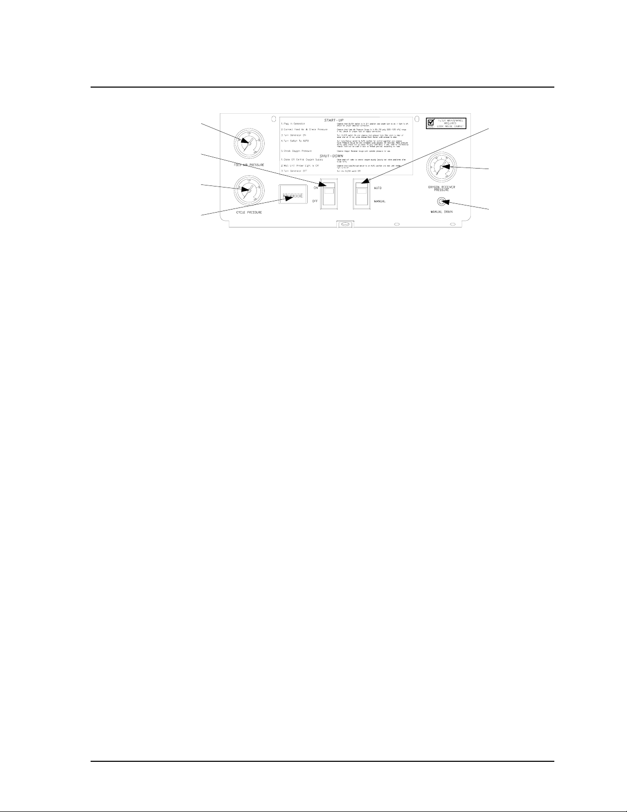
A
Feed Air
Pressure Gauge
On/Off Switch
Cycle Pressure
Gauge
Hour Meter
uto/Manual
Switch
Oxygen
Receiver
Pressure
Gauge
Manual Drain
Button
Figure 4-2 Control Panel — AS-45 and AS-80 Models
On/Off Switch
The l/O power switch starts and stops the operation of the unit. The green indicator
light illuminates to indicate that the oxygen generator is receiving electrical power.
Auto/Manual Switch
The AUTO/MANUAL switch selects the operating mode for the oxygen generator.
In the AUTO position, the oxygen generator cycles on and off to meet oxygen
demand. In the MANUAL position, the oxygen generator cycles continuously. The
amber indicator light on the AUTO/MANUAL switch illuminates only when the
oxygen generator produces oxygen.
Manual Drain Button
The oxygen generator uses an automatic valve to periodically drain excess
moisture extracted from the feed air. The manual drain button allows you to
operate the automatic drain valve manually at any time during operation.
Hour Meter (Not available on AS-20 model)
The hour meter indicates the total number of hours the oxygen generator cycles.
FEED AIR PRESSURE Gauge (Not available on AS-450 — AS-1000 models)
The FEED AIR PRESSURE gauge indicates the pressure of the feed air as the air
enters the generator prior to the feed air regulator.
CYCLE PRESSURE Gauge (Not available on AS-450 — AS-1000 models)
The CYCLE PRESSURE gauge indicates the pressure of the feed air before the air
enters the adsorbers. The feed air regulator controls the pressure indicated on the
CYCLE PRESSURE gauge.
ADSORBER PRESSURE Gauges (AS-450 — AS-1000 models only)
The adsorber pressure gauges indicate the pressure in the two adsorbers.
OXYGEN RECEIVER PRESSURE Gauge
The OXYGEN RECEIVER PRESSURE gauge indicates the oxygen pressure in the
oxygen receiver.
4.1.4 Connections
AS-20—1000 Instruction Manual 4-3
Page 20
12/02 AirSep® Corporation
The oxygen generator provides the connections described below.
Air Inlet
The feed air inlet provides a connection for the feed air hose from the air
compressor.
Oxygen Outlet
The oxygen outlet provides a connection for the oxygen hose to the oxygen
receiver.
Condensate Drain Outlet
The condensate drain outlet provides a connection for a hose to drain condensate
from the oxygen generator filters.
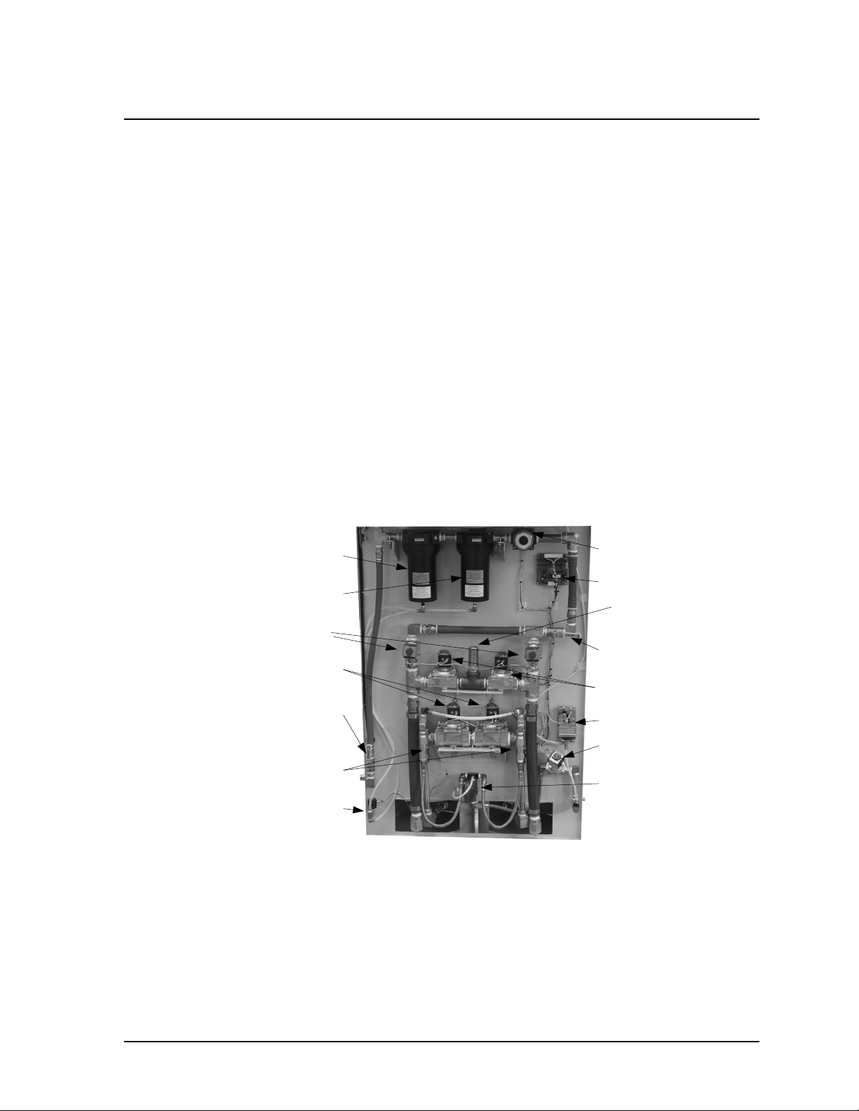
4.2 Manifold Components
Figure 4-4 below illustrates the manifold components of the oxygen generator.
The location and presence of components may vary between the various models
of generators.
Particulate Filter
Coalescing Filter
Feed Air Valves
Equalization Valves
Manual Air Inlet
Valve
Check Valves
Filter Drain Valve
Feed Air Regulator
Circuit Board
Muffler
Manual Filter outlet Valve
Waste Valves
Pressure Switch
Product Valve
Flow Controller
Figure 4-3 Manifold Components —
AS-160 and AS-250 Models
4-4 AS-20—1000 Instruction Manual
Page 21
AirSep® Corporation 12/02
Equalization Valves
Check Valves
Manual Product Valve
Mufflers
Feed Valves
Manual Air Inlet
Particulate Filter
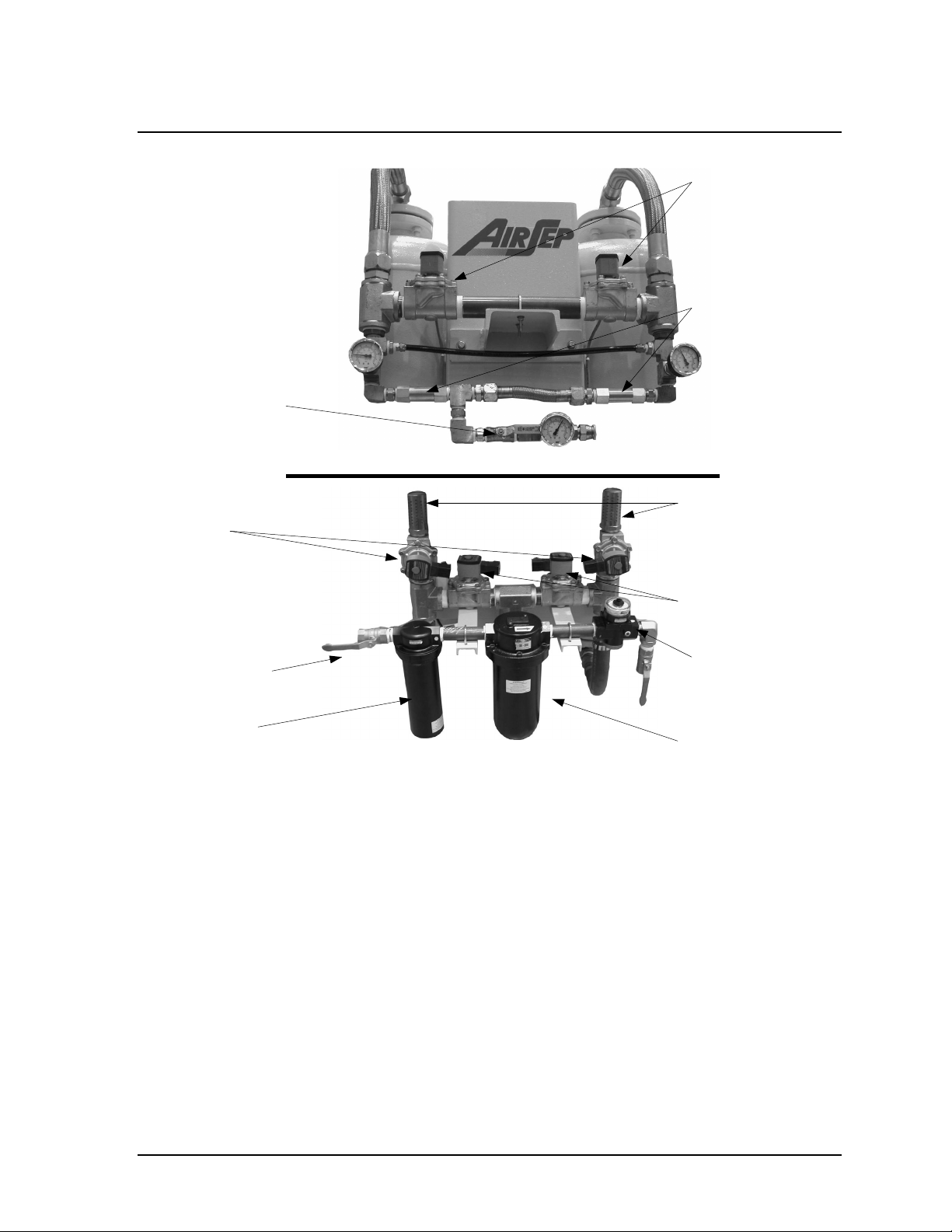
Figure 4-4 Manifold Components —
AS-750 Model
Automatic Equalization Valves
The automatic equalization valves enable the pressure in the adsorbers to equalize
after the product oxygen exits from one of the adsorbers.
Automatic Feed Air Valves
The automatic feed air valves control the flow of the feed air as the air enters the
adsorbers.
Automatic Product Valve
The automatic product valve controls the flow of product oxygen from the
adsorbers.
Waste Valves
Feed Air Regulator
Coalescing Filter
Automatic Waste Valves
The automatic waste valves control the flow of waste gas as it exits the adsorbers.
AS-20—1000 Instruction Manual 4-5
Page 22

12/02 AirSep® Corporation
Check Valves
The check valves ensure that product gas does not flow back into the adsorbers.
Circuit Board
The circuit board controls the cycle time and sequence of operation of the solenoid
and drain valves.
Coalescing Filter
The coalescing filter removes condensed water, oil vapor, and other contaminants
from the feed air before the air enters the adsorbers.
Feed Air Regulator
The feed air regulator is set at the AirSep Corporation factory. The feed air regulator
controls the amount of air pressure at which the oxygen generator cycles.
Filter Drain Valve
This automatic valve removes moisture from the filters through tubing connected to
an outlet at the back of the oxygen generator.
Flow Controller (Not available on AS-20 and AS-450 — AS-1000 models)
The flow controller ensures consistent flow of the delivered product oxygen.
Manual Filter Outlet Valve
This manual valve controls the flow of feed air from the feed air regulator after the
filters to the automatic feed air valves.
Manual Inlet Valve
This manual valve controls the flow of feed air from the air compressor to the filter
assembly.
Particulate Filter (Not available on AS-20 model)
The particulate filter, or prefilter, removes particulates from the feed air before the
air enters the coalescing filter and then the adsorbers.
Pressure Switch
When the oxygen generator operates in Auto mode, the pressure switch monitors
the oxygen pressure in the oxygen receiver. When the pressure in the oxygen
receiver increases to approximately 380-415 kPa (55-60 psig), the pressure switch
circuit closes and the oxygen generator starts a timed shutdown that stops the unit
at the end of the shutdown sequence. When the pressure in the oxygen receiver
decreases to approximately 310 kPa (45 psig), the pressure switch opens to
activate the oxygen generator, and oxygen production begins. When the oxygen
generator operates in Manual mode, the pressure switch circuit remains open and
the oxygen generator cycles continuously.
4-6 AS-20—1000 Instruction Manual
Page 23

AirSep® Corporation 12/02
Relief Valves (not shown)
The relief valves, one on each adsorber, ensure that the pressure in the adsorbers
does not exceed the rated maximum pressure of the adsorbers.
Transformer
The transformer provides the proper voltage for the electrical components of the
oxygen generator.
AS-20—1000 Instruction Manual 4-7
Page 24

Page 25
AirSep® Corporation 12/02
5.0 Installation
5.1 Handling and Unpacking
AirSep Corporation ships the oxygen generator on a wooden skid covered by a
container. The container also includes an accessory box containing all the
accessories for the unit and an instruction manual needed to install the unit
properly. The oxygen receiver, if supplied, is shipped on a separate skid.
To unpack the oxygen generator, follow these guidelines:
1) Inspect the shipping container, and open it immediately upon receipt.
2) If the exterior of the carton is severely damaged, note it on the freight bill
before you sign it.
You must submit a damage claim within 24 hours of receipt.
In the case of concealed or hidden damage, a claim must be
filed within 15 days of receipt. A claim can be filed only by
the consignee. The AirSep Product Warranty does not
shipping damage.
cover
3) Unpack the unit, and remove any protective wrapping and packaging. Retain
the carton and packaging to facilitate future shipping and transporting of the
unit.
4) Place the unit in an upright position, and thoroughly inspect the enclosure
and all external components (e.g., control panel) for damage.
5) Open the enclosure or control panel, and inspect the interior for loose or
damaged parts.
To prevent electrical shock, make sure the main power supply
is disconnected when you remove the enclosure, inspect the
internal components, and install the oxygen generator and
oxygen receiver.
6) Inspect all wiring to ensure that no wires are broken and no push-on
connector is off its terminal. If a wire is disconnected, reconnect the wire to
the most obvious terminal.
7) After inspecting the interior, close the enclosure or control panel on the unit.
8) Locate the instruction manual inside the accessory box. Read the entire
manual before installing and operating the unit.
AS-20—1000 Instruction Manual 5-1
Page 26
12/02 AirSep® Corporation
5.2 Pre-installation Guidelines
Before you install the oxygen generator, and oxygen receiver, if supplied, refer to
the Specifications section in Appendix A of this instruction manual to determine
applicable floor space, feed air, and power requirements for your particular model.
The oxygen generator may use feed air at specifications outside
those shown in Appendix A of this instruction manual; however,
use of such feed air may require modification of the oxygen
generator at the AirSep Corporation factory to ensure the
product oxygen meets the specifications shown in Appendix A.
Consult your sales representative to determine whether your
oxygen generator requires modifications for your application.
Locate the oxygen generator in an area where the ambient air
temperature remains between 4°C (40°F) and 44°C (111°F) to
prevent damage not covered under the AirSep Corporation
Product Warranty.
To prevent fire or electrical shock, locate the oxygen generator
away from rain or any other type of moisture.
Make sure the area that surrounds the oxygen generator is well
ventilated, and provide sufficient space around the unit [at least
one meter (three feet)] to allow for cool air flow as well as to
allow safe operation and maintenance.
AirSep oxygen generators are sold for use in industrial
applications only. Contact AirSep Corporation or an authorized
AirSep representative before you use this unit for any medical
application.
5-2 AS-20—1000 Instruction Manual
Page 27
AirSep® Corporation 12/02
Do not disconnect protective earth:
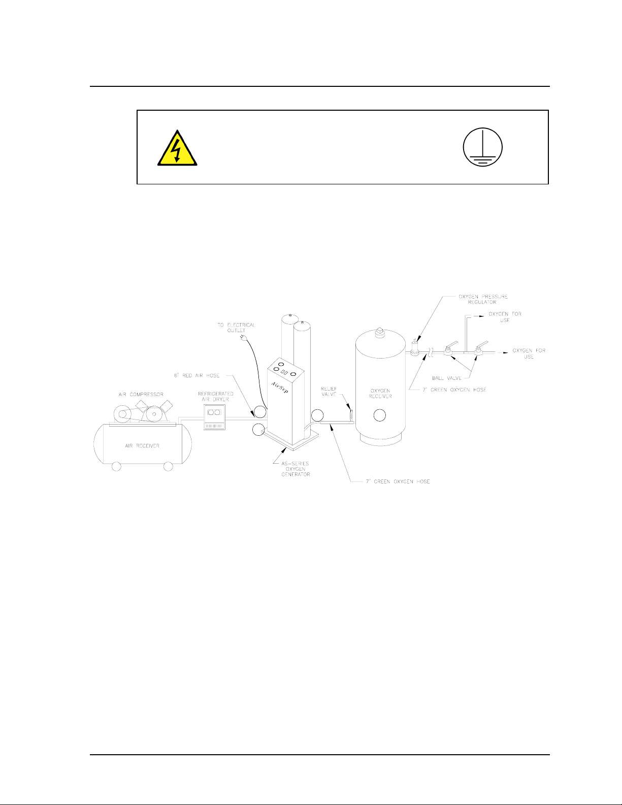
5.3 Installation Instructions
Refer to Figure 5-1 below for the recommended installation arrangement for the
oxygen generator. The numbers in the drawing correspond to the step numbers in
this section.
1
4
Figure 5-1 Typical Installation Arrangement
3
2
1) Connect the red air hose provided with the oxygen generator accessories
from the on-site air supply to the feed air inlet connection on the oxygen
generator. Refer to the Table 5.1 to determine the proper size for the feed air
inlet connection and feed air hose for your model.
AS-20—1000 Instruction Manual 5-3
Page 28
12/02 AirSep® Corporation
Model Feed Air Inlet Connection Size Feed Air Hose Size
AS-20,
AS-45
AS-80
AS-160,
AS-250
AS-450
AS-750 1” NPT Female fitting next to V-2 1” ID minimum
AS-1000 1” NPT Female fitting next to V-2 1” ID minimum
¼” NPT female bulkhead fitting with a ¼” NPT
male x ¼” NPSM ball-end joint adapter
¼” NPT female bulkhead fitting with a ¼” NPT
male x ⅜” NPSM ball-end joint adapter
½” NPT female bulkhead fitting with a ½” NPT
male x ¾” NPSM ball-end joint adapter
¾” NPT female bulkhead fitting with a ¾” NPT
male x ¾” NPSM ball-end joint adapter
Table 5-1 Feed Air Connection Sizes and Hose Sizes
¼” ID minimum
⅜” ID minimum
½” ID minimum
¾” ID minimum
2) Install your oxygen receiver. If AirSep Corporation provided your oxygen
receiver, assemble the receiver as follows (See Figure 5-2.):
5-4 AS-20—1000 Instruction Manual
Page 29

AirSep® Corporation 12/02
Figure 5-2 120 Gallon Oxygen Receiver
a) Connect the relief valve assembly to the oxygen inlet port on the oxygen
receiver. Tighten the connection fully.
b) Connect the hex nipple to the oxygen outlet port on the oxygen
receiver. Tighten the connection fully.
c) Connect the oxygen regulator to the hex nipple at the oxygen outlet port
on the oxygen receiver. Tighten the connection fully.
AS-20—1000 Instruction Manual 5-5
Page 30

12/02 AirSep® Corporation
Use Teflon™ tape to seal the threaded connections on the
oxygen receiver. If AirSep Corporation provided your oxygen
receiver, the threaded connections in the accessory kit were
shipped with Teflon™ tape wrapping already applied.
If AirSep Corporation did not provide your oxygen receiver, make sure your
oxygen receiver is sized properly as specified in Appendix A of this
instruction manual to meet the requirements of your oxygen generator model.
In addition, AirSep Corporation recommends that the oxygen inlet on the
oxygen receiver contain a relief valve and that the oxygen outlet on the
oxygen receiver contain a pressure regulator and pressure gauge or a
manual ball valve and pressure gauge.
3) Connect the green oxygen hose provided with the oxygen generator
accessories from the oxygen outlet connection on the oxygen generator to
the relief valve assembly at the oxygen inlet port on the oxygen receiver.
Refer to the following table to determine the proper size for the oxygen outlet
connection.
Model Oxygen Outlet Connection Size
AS-20, AS-45,
AS-80
AS-160, AS-250
AS-450
AS-750 ¾” NPT Female on tee behind PI-3
AS-1000 ¾” NPT Female on tee behind PI-3
Table 5-2 Oxygen Outlet Connection Sizes
¼” NPT female bulkhead fitting with a
¼” NPT male x B size oxygen adapter
⅜” NPT female bulkhead fitting with a
⅜” NPT male x B size oxygen adapter
⅜” NPT female bulkhead fitting with a
⅜” NPT male x C size oxygen adapter
4) Connect the ⅜” ID nylon tubing provided with the oxygen generator
accessories to the condensate outlet at the rear of the oxygen generator.
Make sure the condensate outlet and nylon tubing do not
become obstructed at any time. This may require a daily drain
system check.
5) Connect the power cord to a grounded electrical outlet. On CE units, a
qualified electrician should install the appropriate grounded electrical
connector on the end of the power cord.
5-6 AS-20—1000 Instruction Manual
Page 31

AirSep® Corporation 12/02
Provide proper voltage from a grounded outlet to the oxygen
generator. Improper voltage causes damage not covered under
the AirSep Corporation Product Warranty.
The oxygen generator is now ready for operation. Refer to Chapter 6 of this
instruction manual before you operate the oxygen generator.
AS-20—1000 Instruction Manual 5-7
Page 32

Page 33

AirSep® Corporation 12/02
6.0 Operation
When you complete installation as described in the previous section, the oxygen
generator is ready for easy start-up and operation. This section of this instruction
manual provides the procedures for start-up and shutdown of the oxygen
generator. Before you start the oxygen generator, read and thoroughly understand
any literature or instruction manuals for the air compressor that will provide the
feed air to the oxygen generator.
6.1 Initial Start-up
To start the oxygen generator for the first time or after an extended or unexpected
shutdown, follow the steps below:
1) Make sure the ON/OFF switch on the control panel is set to OFF.
2) Set the AUTO/MANUAL switch on the control panel to MANUAL.
3) Connect the grounded power cord to a grounded electrical outlet. Make sure
the power circuit cannot be turned off accidentally.
If the power is turned off unexpectedly, the unit will stop cycling.
If your application is using oxygen when the power is off, the
oxygen receiver will depressurize. Refer to Appendix A of this
instruction manual for the length of time you can expect the
oxygen receiver to repressurize.
When you connect the oxygen generator’s plug to a power circuit, the green
light on the ON/OFF switch illuminates to indicate that the oxygen generator
is receiving electrical power.
4) Provide feed air that meets the specification for your model to the oxygen
generator. Make sure the FEED AIR PRESSURE gauge on the control panel
registers pressure within the range of feed air pressures specified in
Appendix A of this instruction manual.
5) Set the ON/OFF switch on the control panel to ON.
6) For AS-450 through AS-1000 models ONLY: Close the manual product
valve (refer to Figure 4-4 for location of valve). The manual product valve on
these units has been configured to enable a predetermined amount of flow
through the valve when closed. This allows the product pressure to build up
even when the valve is closed.
AS-20—1000 Instruction Manual 6-1
Page 34

12/02 AirSep® Corporation
When you start the oxygen generator, air exhausts for 3–5
seconds from the filter drain port on the rear of the unit to remove
any condensate that may be present in the filter bowls. This
removes condensate from the feed air before the feed air enters
the adsorbers. During normal operation, air exhausts from the
filter drain for 3–5 seconds every 10 minutes.
7) Make sure the exhaust from the filter drain does not contain water or oil. If the
exhaust contains water or oil, press the manual drain button on the control
panel until the exhaust no longer contains liquid.
8) To purge oxygen at less than design purity from the oxygen receiver, while
the oxygen generator is running in manual mode, open a manual valve on the
oxygen receiver to vent gas until the gas no longer discharges from the
oxygen receiver, then fully close the manual valve.
Always vent oxygen outside. While venting oxygen, do not
allow smoking or open flame. Do not allow venting oxygen to
come in contact with clothing or hydrocarbon-based materials.
9) Allow the oxygen generator to operate until the OXYGEN RECEIVER
PRESSURE gauge on the control panel registers approximately 380–415
kPa (55-60 psig).
10) Set the AUTO/MANUAL switch on the control panel to AUTO.
When the oxygen generator cycles, i.e., it produces oxygen;
the amber light on the AUTO/MANUAL switch illuminates.
When the unit enters standby, i.e., it remains on but does not
produce oxygen; the amber light on the AUTO/MANUAL switch
shuts off.
11) For AS-450 through AS-1000 models ONLY: Open the manual product
valve
12) Observe the FEED AIR Pressure and CYCLE PRESSURE gauges on the
control panel for at least one cycle (approximately 180 seconds). As the unit
cycles, the feed air pressure should not decrease below 480 kPa (70 psig)
and the peak cycle pressure should not exceed 480 kPa (70 psig). On the
AS-450 through AS-1000 models, observe the readings on the two bed
pressure gauges.
6-2 AS-20—1000 Instruction Manual
Page 35

AirSep® Corporation 12/02
If the feed air pressure decreases below 480 kPa (70 psig) or
the peak cycle pressure exceeds 480 kPa (70 psig), refer to the
troubleshooting chapter of this instruction manual.
13) Observe the OXYGEN RECEIVER PRESSURE gauge on the control panel.
When the pressure in the oxygen receiver increases to approximately 380–
415 kPa (55–60 psig), the oxygen generator stops producing oxygen and
enters standby. When delivery of product oxygen reduces the pressure in the
oxygen receiver below 310 kPa (45 psig), the oxygen generator begins to
cycle and the amber light on the AUTO/MANUAL switch illuminates.
Under normal use, the pressure switch in the oxygen generator
does not require adjustment. If you need to adjust the pressure
switch, refer to the maintenance chapter of this instruction
manual.
14) After the oxygen receiver pressurizes, adjust the pressure regulator at the
outlet of the oxygen receiver until the pressure of the product oxygen meets
the needs of your application.
At this point, the oxygen is ready for use by your application.
6.2 Operation
The oxygen generator can be operated in auto or manual mode depending on the
requirements of your application. To use product oxygen that meets the
specifications for your model listed in Appendix A of this instruction manual, set the
AUTO/MANUAL switch to AUTO to produce oxygen only during times of oxygen
demand. To obtain maximum oxygen purity at less than maximum flow or to obtain
a delivery pressure of 345 kPa (50 psig), set the AUTO/MANUAL switch to
MANUAL to force continuous operation of the unit regardless of the pressure in the
oxygen receiver.
6.3 Shutdown
1) Stop the flow of product oxygen from the oxygen receiver to your application
by fully closing all manual valves between the outlet of the oxygen receiver
and the inlet to your application.
2) Make sure the AUTO/MANUAL switch on the control panel is set to AUTO.
3) Allow the oxygen receiver to repressurize fully. When the oxygen receiver
repressurizes, after a time delay of five cycles, the oxygen generator stops
cycling and the amber indicator light on the AUTO/MANUAL switch shuts off.
AS-20—1000 Instruction Manual 6-3
Page 36

12/02 AirSep® Corporation
Allow the oxygen generator to enter standby during shutdown
to ensure that the oxygen receiver contains oxygen at design
purity during the subsequent restart and also ensure that the
unit shuts down at the proper point in the cycle. Failure to wait
until the oxygen generator enters standby results in temporarily
reduced purity oxygen during the subsequent restart.
4) Set the ON/OFF switch on the control panel to OFF.
5) Set the AUTO/MANUAL switch on the control panel to MANUAL.
6.4 Normal Start-up
To perform a normal start-up, the oxygen generator first
requires a shutdown as described in Section 6.3 — Shutdown.
If the oxygen generator shuts down due to a power loss, follow
the procedure in Section 6.1 — Initial Start-Up to restart the
oxygen generator.
1) Provide feed air that meets the specification for your model to the oxygen
generator. Make sure the FEED AIR PRESSURE gauge on the control panel
registers pressure within the range of feed air pressures specified in
Appendix A of this instruction manual.
2) Set the ON/OFF switch on the control panel to ON.
3) Make sure the exhaust from the filter drain does not contain water or oil. If the
exhaust contains water or oil, press the manual drain button on the control
panel until the exhaust no longer contains liquid.
4) Set the AUTO/MANUAL switch on the control panel to AUTO.
6.5 Extended Shutdown
To shut down the oxygen generator for 24 hours or longer, complete all the steps
in Section 6.3 — Shutdown. In addition, perform the following steps:
1) Fully close all manual valves on the oxygen receiver to isolate the oxygen in
the oxygen receiver, to prevent the loss of pressure in the oxygen receiver
and enable a normal start-up.
2) Turn the oxygen generator off and disconnect power.
6.6 Start-up after an Extended Shutdown
After an extended shutdown or an unexpected shutdown, such as a loss of
electrical power, you must purge the oxygen receiver of any low purity oxygen
6-4 AS-20—1000 Instruction Manual
Page 37

AirSep® Corporation 12/02
before the oxygen generator can supply oxygen within purity specifications. To
purge the oxygen receiver, follow all the steps in Section 6.1 — Initial Start-Up.
AS-20—1000 Instruction Manual 6-5
Page 38

Page 39

AirSep® Corporation 12/02
7.0 Maintenance
The most important maintenance you can perform on the oxygen generator is to
make sure the automatic drain valve for the filters functions properly. Routinely
monitor the operation of this drain valve to ensure the long life of the oxygen
generator. Follow the procedures described in this section of the instruction manual
for daily, semi-annual, and annual maintenance.
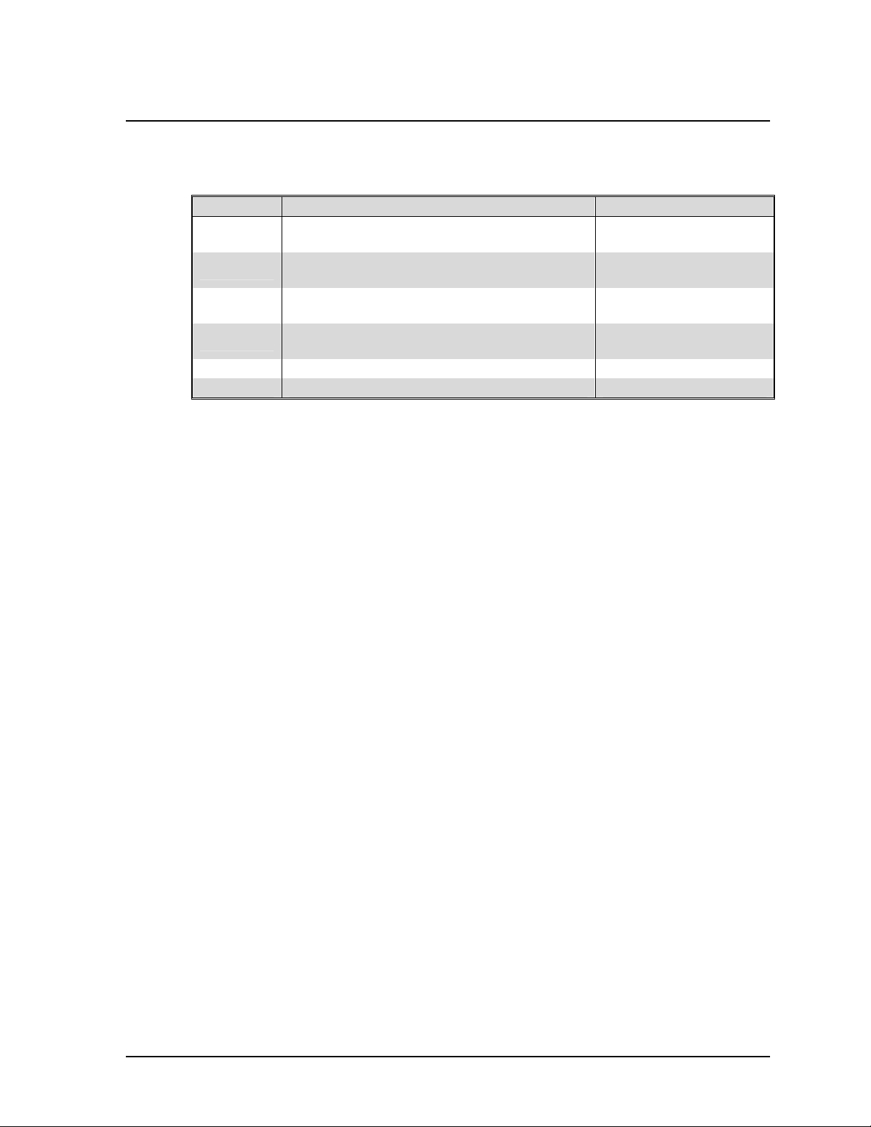
Use the following chart as a guide to perform maintenance on a regular schedule:
Time Period Action
Daily Make sure automatic drain functions properly.
Monthly Inspect filters and bowls. Clean bowls or replace filters as necessary.
Six Months Replace particulate filter element.
Annually Replace coalescing filter element.
Check performance of automatic valves and actuators.
Clean and lubricate feed air regulator.
Table 7-1 Maintenance Chart
7.1 Daily Monitoring
1) Make sure the condensate outlet and tubing for the drain valve is not obstructed.
Condensate should discharge from this outlet or tubing for approximately
three to five seconds every 10 minutes when the ON/OFF switch on the control
panel is set to ON and the green indicator light on the switch illuminates.
2) Press the MANUAL DRAIN button on the control panel and observe the
discharge. The discharge should flow freely and be clear of oil and water
within five seconds.
7.2 Monthly Monitoring
Monthly monitoring requires inspection of the filters and testing the performance of
the automatic drain valve. To perform this procedure, remove the front cover of the
enclosure, depressurize the unit and remove the filter bowls as described in the
following procedures. (See Section 7.3, Removing the Front Cover of the
Enclosure, Section 7.4, Depressurizing the Filters, and Section 7.5, Changing Filter
Elements.) When the filter bowls have been removed and cleaned, perform the
following steps:
1) Inspect the filter element(s). Replace any element(s) that appear damaged or
excessively dirty.
2) Reconnect the drain tubing to the bottom of the bowls.
3) Add approximately two ounces of water to the filter bowls.
4) Re-install the filter bowls, making sure the bowls lock firmly into place.
AS-20—1000 Instruction Manual 7-1
Page 40

12/02 AirSep® Corporation
5) Slowly open fully the manual inlet valve to pressurize the filter bowls.
6) While observing the drain tubing, set the ON/OFF switch on the control panel
to ON and determine whether the automatic drain valve discharges moisture.
7) Fully close the manual inlet valve and depressurize the unit as described
below. (See Section 7.4, Depressurizing the Filters.)
8) Remove the filter bowls as described below. (See Section 7.5, Changing
Filter Elements.) Observe whether the water drained from the bowls.
If the filter bowls still contain water, refer to the troubleshooting chapter of this
instruction manual. If the bowls do not contain water, re-install the bowls,
repressurize the system, and replace the front cover of the enclosure as
described below. (See Section 7.5, Changing Filter Elements.)
7.3 Removing the Front Cover of the
Enclosure (Not available on AS-450 — AS-1000
models)
Disconnect power to the oxygen generator before removing the
front cover of the enclosure.
The front cover of the enclosure protects the components of the
unit from damage and dirt. The cover should remain on the
enclosure at all times and should only be removed for
maintenance or servicing as described in this chapter.
1) Remove the slotted screws that connect the top of the cover to the bottom of
the control panel.
2) Release the four latches on the sides of the cover by pulling the release
levers towards the front of the unit.
3) Carefully grasp the cover and slide it off the unit towards the front of the unit.
The cover is freestanding, so it can be set aside in any location.
7-2 AS-20—1000 Instruction Manual
Page 41

AirSep® Corporation 12/02
A
7.4 Depressurizing the Filters
The oxygen generator filters contain pressurized air. To
perform monthly maintenance or change filter elements safely,
fully depressurize the filter assembly as described in the
procedure in this section. To safely depressurize all oxygen
generator components, refer to the procedure described later in
this chapter. (See Section 7.6, Depressurizing the Oxygen
Generator.)
1) Make sure the AUTO/MAN switch is set to AUTO and allow the oxygen
generator to stop cycling when the oxygen receiver pressurizes fully.
2) Disconnect the oxygen generator from the power supply.
3) Remove the front cover of the enclosure, if applicable. (See Section 7.3,
Removing the Front Cover of the Enclosure.)
4) Fully close the manual inlet valve and manual filter outlet valve. (See Figure
7-1.)
Particulate filter
(not provided on
S-20 model)
Bowl Latches
Drain Tubing
Connections
Manual Inlet Valve
Coalescing Filter
Feed Air Regulator
Filter Bowls
Manual Filter
Outlet Valve
Exhaust Muffler
Pressure Switch
Figure 7-1 Interior View
of AS-45 and AS-80 Models
AS-20—1000 Instruction Manual 7-3
Page 42

12/02 AirSep® Corporation
5) Shut off the feed air supply at the air compressor or air header.
6) Re-install the front cover of the enclosure, if applicable.
7) Reconnect the oxygen generator to the power supply.
8) Press the MANUAL DRAIN button on the control panel until the CYCLE
PRESSURE gauge indicates zero pressure.
If the pressure gauge does not decrease to zero, shut down the
unit and call the AirSep Corporation Commercial Products
Division.
9) Set the ON/OFF switch on the control panel to OFF.
7.5 Changing Filter Elements
The following procedure describes how to change the filter elements for either the
particulate filter (not available on the AS-20 model) semi-annually or the coalescing
filter annually.
1) Depressurize the filter assembly and shut down the oxygen generator. (See
Section 7.4, Depressurizing the Filters.)
Do not attempt to remove the filter bowls until the filter
assembly fully depressurizes as described in Section 7.4.
2) While the unit is depressurized and the power supply is disconnected,
remove the front cover of the enclosure. (See Section 7.3, Removing the Front
Cover of the Enclosure.)
3) To remove the bowl from either filter, push down the bowl latch and rotate the
bowl slight right or left while pulling down on the bowl.
4) When the bowl is free, disconnect the drain tubing from the bottom of the
bowl.
5) Wash the bowl in warm, soapy water, then rinse the bowl.
6) Gently unscrew the old filter element and discard it.
7) If you are replacing a coalescing filter element, remove and discard the black
gasket where the top of the filter element connects to the filter housing.
8) If you are replacing a coalescing filter element, make sure a black gasket is
attached to the top of the new element.
7-4 AS-20—1000 Instruction Manual
Page 43

AirSep® Corporation 12/02
9) Taking care not to touch the filter portion of the new filter element, screw it
into the position from which the old filter was removed.
10) Reconnect the drain tubing to the bottom of the bowl.
11) Re-install the filter bowl, making sure the bowl locks firmly into place.
12) Slowly open fully the manual inlet valve and manual filter outlet valve.
13) Turn on the feed air at the air compressor or air header.
14) Re-install the front cover of the enclosure.
15) Connect the oxygen generator to the power supply.
16) Set the ON/OFF switch on the control panel to ON to operate the oxygen
generator.
7.6 Depressurizing the Oxygen Generator
The oxygen generator operates with pressurized air and
oxygen. To perform maintenance on the unit safely, fully
depressurize the oxygen generator components as described
in the procedure in this section.
1) Shut down the oxygen generator and disconnect the power supply. (See
Section 6.3, Shutdown.)
2) Remove the front cover of the enclosure. (See Section 7.3, Removing the
Front Cover of the Enclosure.)
3) Fully close the manual inlet valve. (See Figure 7-1.)
4) Re-install the front cover of the enclosure.
To fully depressurize the oxygen generator components, make
sure the manual filter outlet valve remains fully open.
5) Connect the oxygen generator to the power supply.
6) Set the ON/OFF switch to ON and set the AUTO/MAN switch to MAN.
7) Allow the unit to operate until gas no longer exhausts from the muffler and
both the FEED AIR and CYCLE PRESSURE gauges indicate zero pressure.
AS-20—1000 Instruction Manual 7-5
Page 44

12/02 AirSep® Corporation
If the pressure gauges do not decrease to zero, shut down the
unit and call the AirSep Corporation Commercial Products
Division.
8) If the unit is depressurized, power down the unit if required and proceed to
perform the maintenance.
7.7 Adjusting the Feed Air Regulator
If the feed air regulator requires adjustment, perform the following procedure. If
applicable, remove the front cover of the enclosure to gain access to the regulator.
(See Section 7.3, Removing the Front Cover of the Enclosure.)
Use extreme caution when performing this procedure since it
requires removal of the front cover of the enclosure while the
unit receives electrical power.
1) Unlock the lock nut on the adjustment knob.
2) To increase feed air pressure, rotate the knob clockwise. To decrease feed
air pressure, rotate the knob counterclockwise.
Make slight adjustments and allow the unit to run through at
least one cycle before making another adjustment. If pressure
readings remain incorrect after the cycle completes, continue
making slight adjustments and cycling the unit until the
pressure is within the manufacturer’s specifications.
7.8 Adjusting the Pressure Switch
Although preset at the AirSep Corporation factory to the pressure switch minimum
and maximum pressures specified in Appendix A of this instruction manual, the
pressure switch may require adjustment if the pressure of the oxygen in the
oxygen receiver registers outside the range specified in Appendix A. Follow the
procedures in this section to adjust the pressure switch settings when required.
7-6 AS-20—1000 Instruction Manual
Page 45

AirSep® Corporation 12/02
Use extreme caution when performing this procedure since it
requires removal of the front cover of the enclosure while the
unit receives electrical power.
Refer to Appendix D of this instruction manual for additional
information on the pressure switch.
1) Set the ON/OFF switch on the oxygen generator control panel to ON.
2) Open the front cover of the enclosure and locate the pressure switch. (See
Figure 7-1.)
Locate the two adjustment screws on top of the pressure switch. The
adjustment screw closest to the rear of the cabinet controls the high pressure
setting. The adjustment screw closest to the front of the cabinet controls the
low pressure setting. Use a ¼-inch wrench or screwdriver to make
adjustments.
The adjustment screw normally requires less than a ¼ turn.
Turn either the high or low adjustment screw ¼-turn clockwise
to increase its pressure setting. Turn either screw
counterclockwise to decrease its pressure setting.
To prevent damage to the pressure switch, do not force the
adjustment screws past their stopping points.
3) Set the AUTO/MAN switch on the oxygen generator control panel to AUTO.
AS-20—1000 Instruction Manual 7-7
Page 46

12/02 AirSep® Corporation
4) Close the oxygen outlet valve on the oxygen receiver. (This valve controls
oxygen flow from the oxygen receiver to your application.)
5) Observe the AUTO/MAN switch. When the amber indicator light on the switch
shuts off to indicate when the oxygen generator stops cycling, note the
pressure on the OXYGEN RECEIVER PRESSURE gauge. If the oxygen
generator continues to cycle and the amber indicator light remains illuminated
when the oxygen receiver pressure exceeds the pressure switch maximum
pressure of 380-415 kPa (55-60 psig), proceed to step 8. If the oxygen
generator stops cycling at approximately the pressure switch maximum
pressure, proceed to step 9. Otherwise, proceed to step 6.
6) Turn the high pressure adjustment screw ¼-turn clockwise to increase the
pressure setting.
7) Repeat step 5.
8) Turn the high pressure adjustment screw ¼-turn counterclockwise to
decrease the pressure setting.
If the oxygen generator stops cycling after five minutes,
proceed to step 9. If the oxygen generator does not stop
cycling after five minutes, repeat step 8.
9) Open the oxygen vent valve on the oxygen receiver.
10) Observe the AUTO/MAN switch on the oxygen generator control panel. When
the amber indicator light on the switch illuminates to indicate when the
oxygen generator starts to cycle, note the pressure on the OXYGEN
RECEIVER PRESSURE gauge. If the oxygen generator does not start to
cycle when the oxygen pressure in the oxygen receiver decreases below the
pressure switch minimum pressure of 310 kPa (45 psig), proceed to step 13.
If the oxygen generator starts to cycle while the oxygen pressure remains
greater than the pressure switch minimum pressure, proceed to step 11. If
the oxygen generator starts to cycle at approximately the pressure switch
minimum pressure, the pressure switch is adjusted properly. Proceed to step
14.
11) Turn the low pressure adjustment screw ¼-turn counterclockwise to decrease
the pressure setting.
12) Repeat step 10.
13) Slowly turn the low adjustment screw clockwise in ¼-turn increments until the
oxygen generator starts to cycle and the amber indicator light on the
AUTO/MAN switch illuminates.
14) Fully close the oxygen vent valve on the oxygen receiver.
7-8 AS-20—1000 Instruction Manual
Page 47

AirSep® Corporation 12/02
15) Close the front cover of the enclosure and resume normal operation of the
oxygen generator.
AS-20—1000 Instruction Manual 7-9
Page 48

Page 49

AirSep® Corporation 12/02
8.0 Troubleshooting
Use the following chart as a guide to troubleshoot the oxygen generator. For
assistance in troubleshooting or repairing the unit, or to order replacement parts,
contact the AirSep Commercial Products Service Department by telephone
Monday through Friday between 7:30 a.m. and 4:30 p.m. Eastern Time. In the
USA or Canada, call 1-800-320-0303. Outside the USA or Canada, call (716) 691-
0202. Send fax inquiries anytime to (716) 691-1255. Address written inquiries to:
AirSep Corporation, 260 Creekside Drive, Buffalo, NY 14228-2075 USA, Attention:
Commercial Products Service Department.
Problem Probable Cause Solution
Oxygen generator does not
cycle. Green light on
ON/OFF switch does not
illuminate.
Blown fuse on unit. Replace fuse in unit.
Oxygen generator operates.
Green light on ON/OFF
switch does not illuminate.
Oxygen generator does not
operate and green light on
ON/OFF switch illuminates.
AUTO/MAN switch set to
MAN and amber light on
AUTO/MAN switch does not
illuminate.
Defective ON/OFF switch. Replace switch.
Defective circuit board. Replace circuit board.
Low voltage. Check power supply.
Oxygen generator cycles
with AUTO/MAN switch set
to MAN. Amber light on
AUTO/MAN switch does not
illuminate.
Defective circuit board. Replace circuit board.
No electrical power to
control cabinet or blown
fuse on unit.
Light bulb on ON/OFF
switch burned out.
Loose or defective wire to
switch.
ON/OFF switch set to
OFF.
Loose or defective power
wire to circuit board.
Light bulb on AUTO/MAN
switch burned out.
Loose or defective wire to
switch.
Make sure unit is plugged
into wall outlet and that
wall outlet receives power.
Replace switch or replace
the bulb in AS-160 – AS-
1000.
Repair or replace wire.
Set ON/OFF switch to ON.
Repair or replace wire.
Replace switch or replace
the bulb in AS-160 – AS-
1000.
Repair or replace wire.
AS-20—1000 Instruction Manual 8-1
Page 50

12/02 AirSep® Corporation
Problem Probable Cause Solution
Oxygen generator does not
operate and green light on
ON/OFF switch illuminates.
Amber light on AUTO/MAN
switch does not illuminate
and switch set to AUTO.
Pressure of oxygen is less
than 275 kPa (40 psig).
Defective ON/OFF switch. Replace switch.
Defective pressure switch. Replace pressure switch.
Defective circuit board. Replace circuit board.
Oxygen generator operates
continuously. Amber light on
AUTO/MAN switch
illuminates and switch set to
AUTO. Pressure of oxygen
exceeds 400 kPa (58 psig).
Defective pressure switch. Replace pressure switch.
Defective circuit board. Replace circuit board.
Oxygen generator operates
continuously. Pressure of
oxygen at specified purity is
less than 275 kPa (40 psig).
ON/OFF switch set to
OFF.
Loose or defective power
wire to circuit board.
Pressure switch
improperly set.
Pressure switch
improperly set.
Loose or defective power
wire to pressure switch.
Defective AUTO/MAN
switch.
Inadequate feed air
pressure.
Inadequate cycle
pressure.
Oxygen demand exceeds
oxygen generator
capacity.
Set ON/OFF switch to ON.
Repair or replace wire.
Adjust pressure switch as
described in Chapter 7.
Adjust pressure switch as
described in Chapter 7.
Repair or replace wire.
Replace switch.
Make sure feed air valves
remain fully open and lines
are not obstructed.
Adjust or replace feed air
regulator.
Check oxygen usage or
check unit and oxygen
hoses and piping for leaks.
8-2 AS-20—1000 Instruction Manual
Page 51

AirSep® Corporation 12/02
Problem Probable Cause Solution
Oxygen purity below
specified purity (50–70%).
Momentary power loss.
Inadequate feed air.
Torn valve diaphragm.
Defective coil. Replace coil.
Defective valve. Rebuild valve.
Valve makes loud
“chattering” noise.
Dirty valve. Clean or rebuild valve.
Worn valve core. Rebuild valve.
Defective EMI filter. Replace EMI filter.
Very low oxygen output
(21–50%).
Plugged muffler. Replace muffler.
Low purity oxygen during
initial start-up.
Unit shut down for
extended period—no
pressure in oxygen system.
Valves not cycling
properly.
Improperly wired or
defective circuit board.
Solenoid valve not
functioning properly.
Check for the following
causes:
Loose or defective wire to
valve.
Defective circuit board.
(No power output to
valve.)
Valve remains energized
and open.
Worn internal parts on
valve.
Low voltage. Check power supply.
Low voltage circuit board
output.
Leaking check valves.
Contaminated molecular
sieve in adsorbers.
Start unit as described in
Chapter 6.
Start unit as described in
Chapter 6.
Vent low purity oxygen
from system as described
in Chapter 6.
Check air lines for
obstructions or adjust or
replace feed air regulator.
See valve sequence in
Appendix A.
Replace circuit board.
Identify defective valve
and rebuild valve.
Repair or replace wire.
Replace circuit board.
Replace circuit board.
Rebuild valve.
Replace circuit board.
Clean or replace check
valves.
Replace molecular sieve.
AS-20—1000 Instruction Manual 8-3
Page 52

12/02 AirSep® Corporation
Problem Probable Cause Solution
Oxygen generator outputs
particulates (dusting).
Feed air regulator leaks out
bleed orifice.
Oxygen generator relief
valves open.
Defective relief valve. Replace relief valve.
Filter drain valve remains
open. (Valve not energized.)
Filter drain valve remains
energized.
Defective circuit board. Replace circuit board.
Filter drain valve does not
energize.
Defective valve coil. Replace valve.
Filter drain valve energizes
with unit pressurized, but no
air exhausts.
Excess feed air pressure.
Feed air regulator set
above 485 kPa (70 psig).
Contaminated molecular
sieve in adsorbers.
System not cycling
properly.
Stuck feed air regulator
main valve assembly.
Defective main valve
assembly seat.
Cycle pressure exceeds
485 kPa (70 psig)
maximum.
Stuck feed air regulator
main valve assembly.
Frozen feed air regulator
main valve assembly.
Defective cycle pressure
gauge.
Valve obstructed. Clean or replace valve.
MANUAL DRAIN valve
button stuck.
Defective MANUAL DRAIN
valve button.
Loose or defective wire to
valve.
Valve core stuck in closed
position.
Defective circuit board.
(No power output to
valve.)
Drain valve obstructed or
stuck in closed position.
Drain tubing obstructed or
pinched.
Make sure maximum feed
air pressure does not
exceed 1,035 kPa (150
psig).
Adjust feed air regulator.
Contaminated molecular
sieve in adsorbers.
Check and repair or
replace faulty wiring
and/or circuit board.
Clean and lubricate main
regulator valve assembly.
Rebuild or replace
regulator.
Adjust feed air regulator.
Rebuild or replace
regulator.
Make sure ambient
temperature exceeds 4°C
(40°F).
Replace gauge and adjust
feed air regulator.
Replace button.
Replace button.
Repair or replace wire.
Replace valve.
Replace circuit board.
Clean or replace valve.
Clean or replace tubing.
8-4 AS-20—1000 Instruction Manual
Page 53

AirSep® Corporation 12/02
A Appendix Technical Data
Specifications
Data in this section refer to standard AS-20 through AS-1000 model oxygen
generators. The oxygen generators may use feed air at specifications outside
those shown; however, use of such feed air may require modification of the oxygen
generators at the AirSep Corporation factory to ensure the product oxygen meets
the design specifications. Consult your sales representative to determine whether
your oxygen generator requires modifications for your application.
AS-20
Oxygen output: 20 SCF/hr at 0–45 psig*
0.53 Nm3/hr at 0–310 kPa**
Oxygen purity: 90% minimum
Oxygen dew point: -73°C (-100°F)
Dimensions: 13 x 11 x 57 in. (W x D x H)
33 x 28 x 145 cm (W x D x H)
Approximate weight: 134 lb
61 kg
Feed Air Requirements
Flow: 5.3 SCF/min* (0.14 Nm3/min**)
Pressure: 90 psig (620 kPa) minimum
Temperature: 50°C (122°F) maximum
Power requirements: 120 VAC, 50 Hz, Single Phase, 60 W, 0.5 Amp
120 VAC, 60 Hz, Single Phase, 60 W, 0.5 Amp
240 VAC, 50 Hz, Single Phase, 60 W, 0.25 Amp
240 VAC, 60 Hz, Single Phase, 60 W, 0.25 Amp
*SCF (standard cubic foot) gas measured at 1 atmosphere and 70°F.
3
**Nm (normal cubic meters) gas measured at 1 atmosphere and 0°C.
AS-20—1000 Instruction Manual A-1
Page 54

12/02 AirSep® Corporation
AS-45
Oxygen output: 45 SCF/hr at 0–45 psig*
1.18 Nm3/hr at 0–310 kPa**
Oxygen purity: 90% minimum
Oxygen dew point: -73°C
-100°F
Dimensions: 17 x 15 x 58 in. (W x D x H)
43 x 38 x 147 cm (W x D x H)
Approximate weight: 238 lb
108 kg
Feed Air Requirements
Flow: 13.3 SCF/min*
0.35 Nm3/min**
Pressure: 90 psig minimum
620 kPa minimum
Temperature: 50°C maximum
122°F maximum
Power requirements: 120 VAC, 50 Hz, Single Phase, 60 W, 0.5 Amp
120 VAC, 60 Hz, Single Phase, 60 W, 0.5 Amp
240 VAC, 50 Hz, Single Phase, 60 W, 0.25 Amp
240 VAC, 60 Hz, Single Phase, 60 W, 0.25 Amp
*SCF (standard cubic foot) gas measured at 1 atmosphere and 70°F.
3
**Nm (normal cubic meters) gas measured at 1 atmosphere and 0°C.
A-2 AS-20—1000 Instruction Manual
Page 55

AirSep® Corporation 12/02
AS-80
Oxygen output: 80 SCF/hr at 0–45 psig*
2.10 Nm3/hr at 0–310 kPa**
Oxygen purity: 90% minimum
Oxygen dew point: -73°C
-100°F
Dimensions: 20 x 16 x 60 in. (W x D x H)
51 x 41 x 152 cm (W x D x H)
Approximate weight: 338 lb
153 kg
Feed Air Requirements
Flow: 20 SCF/min*
0.53 Nm3/min**
Pressure: 90 psig minimum
620 kPa minimum
Temperature: 50°C maximum
122°F maximum
Power requirements: 120 VAC, 50 Hz, Single Phase, 60 W, 0.5 Amp
120 VAC, 60 Hz, Single Phase, 60 W, 0.5 Amp
240 VAC, 50 Hz, Single Phase, 60 W, 0.25 Amp
240 VAC, 60 Hz, Single Phase, 60 W, 0.25 Amp
*SCF (standard cubic foot) gas measured at 1 atmosphere and 70°F.
3
**Nm (normal cubic meters) gas measured at 1 atmosphere and 0°C.
AS-20—1000 Instruction Manual A-3
Page 56

12/02 AirSep® Corporation
AS-160
Oxygen output: 160 SCF/hr at 0–45 psig*
4.21 Nm3/hr at 0–310 kPa**
Oxygen purity: 90% minimum
Oxygen dew point: -73°C
-100°F
Dimensions: 27 x 26 x 66 in. (W x D x H)
69 x 66 x 168 cm (W x D x H)
Approximate weight: 722 lb
328 kg
Feed Air Requirements
Flow: 31.0 SCF/min*
0.81 Nm3/min**
Pressure: 90 psig minimum
620 kPa minimum
Temperature: 50°C maximum
122°F maximum
Power requirements: 120 VAC, 50 Hz, Single Phase, 60 W, 0.5 Amp
120 VAC, 60 Hz, Single Phase, 60 W, 0.5 Amp
240 VAC, 50 Hz, Single Phase, 60 W, 0.25 Amp
240 VAC, 60 Hz, Single Phase, 60 W, 0.25 Amp
*SCF (standard cubic foot) gas measured at 1 atmosphere and 70°F.
3
**Nm (normal cubic meters) gas measured at 1 atmosphere and 0°C.
A-4 AS-20—1000 Instruction Manual
Page 57

AirSep® Corporation 12/02
AS-250
Oxygen output: 250 SCF/hr at 0–45 psig*
6.57 Nm3/hr at 0–310 kPa**
Oxygen purity: 90% minimum
Oxygen dew point: -73°C
-100°F
Dimensions: 31 x 28 x 76 in. (W x D x H)
79 x 71 x 193 cm (W x D x H)
Approximate weight: 1,034 lb
469 kg
Feed Air Requirements
Flow: 46.7 SCF/min*
01.23 Nm3/min**
Pressure: 90 psig minimum
620 kPa minimum
Temperature: 50°C maximum
122°F maximum
Power requirements: 120 VAC, 50 Hz, Single Phase, 60 W, 0.5 Amp
120 VAC, 60 Hz, Single Phase, 60 W, 0.5 Amp
240 VAC, 50 Hz, Single Phase, 60 W, 0.25 Amp
240 VAC, 60 Hz, Single Phase, 60 W, 0.25 Amp
*SCF (standard cubic foot) gas measured at 1 atmosphere and 70°F.
3
**Nm (normal cubic meters) gas measured at 1 atmosphere and 0°C.
AS-20—1000 Instruction Manual A-5
Page 58

12/02 AirSep® Corporation
AS-450
Oxygen output: 450 SCF/hr at 0–45 psig*
11.83 Nm3/hr at 0–310 kPa**
Oxygen purity: 90% minimum
Oxygen dew point: -73°C
-100°F
Dimensions: 42 x 34 x 79 in. (W x D x H)
107 x 86 x 201 cm (W x D x H)
Approximate weight: 1972 lb
894 kg
Feed Air Requirements
Flow: 83.3 SCF/min*
2.19 Nm3/min**
Pressure: 90 psig minimum
620 kPa minimum
Temperature: 50°C maximum
122°F maximum
Power requirements: 120 VAC, 50 Hz, Single Phase, 60 W, 0.5 Amp
120 VAC, 60 Hz, Single Phase, 60 W, 0.5 Amp
240 VAC, 50 Hz, Single Phase, 60 W, 0.25 Amp
240 VAC, 60 Hz, Single Phase, 60 W, 0.25 Amp
*SCF (standard cubic foot) gas measured at 1 atmosphere and 70°F.
3
**Nm (normal cubic meters) gas measured at 1 atmosphere and 0°C.
A-6 AS-20—1000 Instruction Manual
Page 59

AirSep® Corporation 12/02
AS-750
Oxygen output: 750 SCF/hr at 0–45 psig*
19.72 Nm3/hr at 0–310 kPa**
Oxygen purity: 90% minimum
Oxygen dew point: -73°C
-100°F
Dimensions: 58 x 40 x 100 in. (W x D x H)
147 x 102 x 254 cm (W x D x H)
Approximate weight: 2530 lb
1148 kg
Feed Air Requirements
Flow: 130 SCF/min*
3.80 Nm3/min**
Pressure: 90 psig minimum
620 kPa minimum
Temperature: 50°C maximum
122°F maximum
Power requirements: 120 VAC, 50 Hz, Single Phase, 60 W, 0.5 Amp
120 VAC, 60 Hz, Single Phase, 60 W, 0.5 Amp
240 VAC, 50 Hz, Single Phase, 60 W, 0.25 Amp
240 VAC, 60 Hz, Single Phase, 60 W, 0.25 Amp
*SCF (standard cubic foot) gas measured at 1 atmosphere and 70°F.
3
**Nm (normal cubic meters) gas measured at 1 atmosphere and 0°C.
AS-20—1000 Instruction Manual A-7
Page 60

12/02 AirSep® Corporation
AS-1000
Oxygen output: 1000 SCF/hr at 0–45 psig*
28.32 Nm3/hr at 0–310 kPa**
Oxygen purity: 90% minimum
Oxygen dew point: -73°C
-100°F
Dimensions: 62 x 40 x 106 in. (W x D x H)
158 x 102 x 270 cm (W x D x H)
Approximate weight: 3500 lb
1588 kg
Feed Air Requirements
Flow: 160 SCF/min*
4.53 Nm3/min**
Pressure: 90 psig minimum
620 kPa minimum
Temperature: 50°C maximum
122°F maximum
Power requirements: 120 VAC, 50 Hz, Single Phase, 60 W, 0.5 Amp
120 VAC, 60 Hz, Single Phase, 60 W, 0.5 Amp
240 VAC, 50 Hz, Single Phase, 60 W, 0.25 Amp
240 VAC, 60 Hz, Single Phase, 60 W, 0.25 Amp
*SCF (standard cubic foot) gas measured at 1 atmosphere and 70°F.
3
**Nm (normal cubic meters) gas measured at 1 atmosphere and 0°C.
A-8 AS-20—1000 Instruction Manual
Page 61

AirSep® Corporation 12/02
Operating Data
AS-20—1000 Instruction Manual A-9
Page 62

12/02 AirSep® Corporation
Drawings
A-10 AS-20—1000 Instruction Manual
Page 63

AirSep® Corporation 12/02
Figure 2 General Arrangement Drawing – AS-20
AS-20—1000 Instruction Manual A-11
Page 64

12/02 AirSep® Corporation
Figure 3 Flow Schematic – AS-20
A-12 AS-20—1000 Instruction Manual
Page 65

AirSep® Corporation 12/02
Figure 4 Electrical Schematic – AS-20 (120V)
Figure 5 Electrical Schematic – AS-20 (220V)
AS-20—1000 Instruction Manual A-13
Page 66

12/02 AirSep® Corporation
Figure 6 General Arrangement Drawing – AS-45
A-14 AS-20—1000 Instruction Manual
Page 67

AirSep® Corporation 12/02
Figure 7 General Arrangement Drawing – AS-80
AS-20—1000 Instruction Manual A-15
Page 68

12/02 AirSep® Corporation
Figure 8 General Arrangement Drawing – AS-160
A-16 AS-20—1000 Instruction Manual
Page 69

AirSep® Corporation 12/02
Figure 9 General Arrangement Drawing – AS-250
AS-20—1000 Instruction Manual A-17
Page 70

12/02 AirSep® Corporation
Figure 10 Flow Diagram – AS-45 through AS-250
A-18 AS-20—1000 Instruction Manual
Page 71

AirSep® Corporation 12/02
Figure 11 Electrical Diagram – AS-45 through AS-250 (120V)
Figure 12 Electrical Diagram – AS-45 through AS-250 (220V)
AS-20—1000 Instruction Manual A-19
Page 72

12/02 AirSep® Corporation
Figure 13 General Arrangement Drawing – AS-450
A-20 AS-20—1000 Instruction Manual
Page 73

AirSep® Corporation 12/02
Figure 14 General Arrangement Drawing – AS-750
AS-20—1000 Instruction Manual A-21
Page 74

12/02 AirSep® Corporation
Figure 15 Flow Diagram – AS-450 through AS-750
A-22 AS-20—1000 Instruction Manual
Page 75

AirSep® Corporation 12/02
Figure 16 Electrical Schematic – AS-450 through AS-750 (120V)
Figure 17 Electrical Schematic – AS-450 through AS-750 (220V)
AS-20—1000 Instruction Manual A-23
Page 76

12/02 AirSep® Corporation
Figure 18 General Arrangement Drawing– AS-1000
A-24 AS-20—1000 Instruction Manual
Page 77

AirSep® Corporation 12/02
Figure 19 Electrical Schematic – AS-1000 (120V)
Figure 20 Electrical Schematic – AS-1000 (220V)
AS-20—1000 Instruction Manual A-25
Page 78

12/02 AirSep® Corporation
Figure 21 Flow Diagram – AS-1000
A-26 AS-20—1000 Instruction Manual
Page 79

AirSep® Corporation 12/02
B Appendix Warranty/Returns
Product Warranty
AirSep Corporation (“AirSep”) warrants to the party purchasing from AirSep (the
“original purchaser”) the PSA oxygen generator to be free from defect in parts and
workmanship for one year from the date of start-up, not to exceed eighteen (18)
months from the date of shipment to the original purchaser, under normal use,
maintenance and operation*. TO THE EXTENT PERMITTED UNDER APPLICABLE
LAW, ALL WARRANTIES WITH RESPECT TO SUCH UNIT SHALL ONLY EXTEND
TO AND BE FOR THE BENEFIT OF THE ORIGINAL PURCHASER AND SHALL
NOT BE ASSIGNABLE TO, EXTEND TO OR BE FOR THE BENEFIT OF ANY
OTHER PARTY. AirSep’s obligations under this warranty are limited, at AirSep’s
option, to the repair, replacement or refunding the purchase price of any such unit
of equipment (or part thereof) found by AirSep to be defective in parts or
workmanship; provided, however, that AirSep shall have no obligation hereunder
with respect to a defective part unless it receives written notice of such defect prior
to the expiration of the applicable warranty period as referenced above.
Each unit of equipment for which a warranty claim is asserted shall, at the request
of AirSep, be returned on a prepaid basis with proof of purchase date to the AirSep
factory specified by AirSep at the expense of the original purchaser. Replacement
parts shall be warranted as stated above for the unexpired portion of the original
warranty. This warranty does not extend to any unit or part subjected to misuse,
accident, improper maintenance or application, or which has been repaired or
altered outside of the AirSep factory without the express prior written authorization
of AirSep.
Notwithstanding anything to the contrary contained herein, during the applicable
warranty period, as specified above, AirSep will pay the cost of return freight
charges to the original purchaser, provided an authorized AirSep representative
approved return of the unit or parts, for any equipment found by AirSep to be
defective. For warranty repairs performed during the first 90 days from the date of
invoice, AirSep will pay freight both ways. After the applicable parts warranty
period has expired, the original purchaser is responsible for freight both ways.
* Please refer to the appropriate product documentation for applicable installation and operating
requirements.
AS-20—1000 Instruction Manual B-1
Page 80

12/02 AirSep® Corporation
Limits of Liability
THE FOREGOING WARRANTY IS THE ONLY WARRANTY MADE BY AIRSEP
WITH RESPECT TO THE EQUIPMENT (OR ANY PART THEREOF) AND IS IN
LIEU OF ANY OTHER WARRANTY, EXPRESSED OR IMPLIED, IN FACT OR IN
LAW, INCLUDING WITHOUT LIMITATION ANY WARRANTIES OF
MERCHANTABILITY OR FITNESS FOR ANY PARTICULAR PURPOSE. IT IS
EXPRESSLY UNDERSTOOD THAT THE SOLE AND EXCLUSIVE REMEDY FOR
ANY DEFECT IN PARTS OR WORKMANSHIP IS LIMITED TO ENFORCEMENT
OF AIRSEP’S OBLIGATIONS AS SET FORTH ABOVE, AND AIRSEP SHALL NOT
BE LIABLE TO ORIGINAL PURCHASER OR ANY OTHER PARTY FOR LOSS OF
USE OF THE EQUIPMENT, LOST PROFITS OR FOR ANY OTHER SPECIAL,
INDIRECT, INCIDENTAL, OR CONSEQUENTIAL DAMAGES (EVEN IF AIRSEP
HAS BEEN ADVISED OF THE POSSIBILITY OF SUCH DAMAGES).
AirSep oxygen generators are sold for use in industrial
applications only. Contact AirSep Corporation or an authorized
AirSep Corporation representative before you use this unit for
any medical application.
Returning the Oxygen Generator or a Component for Service
If the oxygen generator or a defective part requires service, contact your distributor.
If instructed by your distributor to contact AirSep Corporation, follow the procedure
below to return the oxygen generator or a component for service or credit.
1) Obtain a Return Goods Authorization (RGA) number from the AirSep
Commercial Products Service Department. (Refer to Chapter 8,
Troubleshooting for information about contacting AirSep Corporation.)
Before you call for service assistance, have the following information readily
available:
Oxygen Generator Model
Serial Number
Hours of Use
Invoice Date
AirSep Corporation issues no credit for any warranted item until
you present the model number, serial number, and invoice date
of the oxygen generator, and defective part is returned to
AirSep Corporation.
2) Write the RGA number clearly on the outside of the shipping container.
B-2 AS-20—1000 Instruction Manual
Page 81

AirSep® Corporation 12/02
AirSep Corporation accepts no item(s) for service or credit
unless prior written authorization was issued by AirSep
Corporation.
3) Return item(s) in their original packaging material. Pack merchandise for a
safe return. AirSep Corporation assumes no responsibility for damage that
occurs in transit. Any damage to the oxygen generator or a component
because of failure to follow this procedure is the sole responsibility of the
customer.
Return item(s) on a freight prepaid basis only.
AS-20—1000 Instruction Manual B-3
Page 82

Page 83

AirSep® Corporation 12/02
C Appendix Parts List
Use the following lists to order parts for the oxygen generator. To order, please
contact your distributor. If instructed by your distributor to contact AirSep
Corporation, contact the AirSep Commercial Products Service Department as
described in Chapter 8, Troubleshooting. If the list does not contain the part you
require, please provide a precise description of the part when you call.
AS-20—1000 Instruction Manual C-1
Page 84

12/02 AirSep® Corporation
AS-20 Parts
Model AS-20 Spare Parts
Item Qty Per Part Number
8,000 Hour Kit/1 Year
Microalescer Element 1 FI019-1
16,000 Hour Kit/2 Year
Microalescer Element 2 FI019-1
1/4" Feed Valve Rebuild Kit 2 VA089-1
1/4" Waste Valve Rebuild Kit 2 VA089-1
1/4" Equalization Valve Rebuild Kit 2 VA088-1
1/8" Product Valve 1 VA009-1
1/8" Drain Valve 1 VA009-2
40,000 Hour Kit/5 Year
Microalescer Element 5 FI019-1
1/4" Feed Valve Rebuild Kit 4 VA089-1
1/4" Waste Valve Rebuild Kit 4 VA089-1
1/4" Equalization Valve Rebuild Kit 4 VA088-1
1/8" Product Valve 2 VA009-1
1/8" Drain Valve 2 VA009-2
Emergency Kit
Microalescer Element 1 FI019-1
1/4" Feed Valve Rebuild Kit 1 VA089-1
1/4" Waste Valve Rebuild Kit 1 VA089-1
1/4" Equalization Valve Rebuild Kit 1 VA088-1
1/8" Product Valve 1 VA009-1
1/8" Drain Valve 1 VA009-2
PC Board 1 CB039-1
3 Amp Fuse 4 FU004-1
Check Valve 1 VA141-2
1 /4" Equalization,Feed,Waste Valve Coil 1 VA110-1
KI180-1
KI181-1
KI182-1
KI183-1
C-2 AS-20—1000 Instruction Manual
Page 85

AirSep® Corporation 12/02
AS-45 Parts
Model AS-45 Spare Parts
Item Qty Per Part Number
8,000 Hour Kit/1 Year
Prefilter Element 1/4000 hrs 2 FI029-1
Microalescer Element 1/8000 hrs 1 FI020-1
16,000 Hour Kit/2 Year
Prefilter Element 4 FI029-1
Microalescer Element 2 FI020-1
1/4" Feed Valve Rebuild Kit 2 VA089-1
3/8" Waste Valve Rebuild Kit 2 VA096-1
3/8" Equalization Valve Rebuild Kit 2 VA095-1
1/8" Product Valve 1 VA009-1
1/8" Drain Valve 1 VA009-2
40,000 Hour Kit/5 Year
Prefilter Element 10 FI029-1
Microalescer Element 5 FI020-1
1/4" Feed Valve Rebuild Kit 4 VA089-1
3/8" Waste Valve Rebuild Kit 4 VA096-1
3/8" Equalization Valve Rebuild Kit 4 VA095-1
1/8" Product Valve 2 VA009-1
1/8" Drain Valve 2 VA009-2
Emergency Kit
Prefilter Element 1 FI029-1
Microalescer Element 1 FI020-1
1/4" Feed Valve Rebuild Kit 1 VA089-1
3/8" Waste Valve Rebuild Kit 1 VA096-1
3/8" Equalization Valve Rebuild Kit 1 VA095-1
1/8" Product Valve 1 VA009-1
1/8" Drain Valve 1 VA009-2
PC Board 1 CB039-2
3 Amp Fuse 4 FU004-1
Check Valve 2 VA141-2
1/4" Feed Valve Coil 1 VA110-1
3/8" Waste,Equalization Valve Coil 1 VA112-1
KI184-1
KI185-1
KI186-1
KI187-1
AS-20—1000 Instruction Manual C-3
Page 86

12/02 AirSep® Corporation
AS-80 Parts
Model AS-80 Spare Parts
Item Qty Per Part Number
8,000 Hour Kit/1 Year
Prefilter Element 1/4000 hrs 2 FI029-1
Microalescer Element 1/8000 hrs 1 FI020-1
16,000 Hour Kit/2 Year
Prefilter Element 4 FI029-1
Microalescer Element 2 FI020-1
3/8" Feed Valve Rebuild Kit 2 VA096-1
3/8" Waste Valve Rebuild Kit 2 VA096-1
3/8" Equalization Valve Rebuild Kit 2 VA095-1
1/4" Product Valve Rebuild Kit 1 VA088-1
1/8" Drain Valve 1 VA009-2
40,000 Hour Kit/5 Year
Prefilter Element 10 FI029-1
Microalescer Element 5 FI020-1
3/8" Feed Valve Rebuild Kit 4 VA096-1
3/8" Waste Valve Rebuild Kit 4 VA096-1
3/8" Equalization Valve Rebuild Kit 4 VA095-1
1/4" Product Valve Rebuild Kit 2 VA088-1
1/8" Drain Valve 2 VA009-2
Emergency Kit
Prefilter Element 1 FI029-1
Microalescer Element 1 FI020-1
3/8" Feed Valve Rebuild Kit 1 VA096-1
3/8" Waste Valve Rebuild Kit 1 VA096-1
3/8" Equalization Valve Rebuild Kit 1 VA095-1
1/4" Product Valve Rebuild Kit 1 VA088-1
1/8" Drain Valve 1 VA009-2
PC Board 1 CB039-3
3 Amp Fuse 4 FU004-1
Check Valve 1 VA141-2
1/4" Product Valve Coil 1 VA110-1
3/8" Feed,Waste,Equalization Valve Coil 1 VA112-1
KI184-1
KI188-1
KI189-1
KI190-1
C-4 AS-20—1000 Instruction Manual
Page 87

AirSep® Corporation 12/02
AS-160 Parts
Model AS-160 Spare Parts
Item Qty Per Part Number
8,000 Hour Kit/1 Year
Prefilter Element 1/4000 hrs 2 FI029-1
Microalescer Element 1/8000 hrs 1 FI016-1
16,000 Hour Kit/2 Year
Prefilter Element 4 FI029-1
Microalescer Element 2 FI016-1
3/8" Feed Valve Rebuild Kit 2 VA096-1
3/4" Waste Valve Rebuild Kit 2 VA101-1
3/4" Equalization Valve Rebuild Kit 2 VA100-1
3/8" Product Valve Rebuild Kit 1 VA095-1
1/8" Drain valve 1 VA009-2
40,000 Hour Kit/5 Year
Prefilter Element 10 FI029-1
Microalescer Element 5 FI016-1
3/8" Feed Valve Rebuild Kit 4 VA096-1
3/4" Waste Valve Rebuild Kit 4 VA101-1
3/4" Equalization Valve Rebuild Kit 4 VA100-1
3/8" Product Valve Rebuild Kit 2 VA095-1
1/8" Drain valve 2 VA009-2
Emergency Kit
Prefilter Element 1 FI029-1
Microalescer Element 1 FI016-1
3/8" Feed Valve Rebuild Kit 1 VA096-1
3/4" Waste Valve Rebuild Kit 1 VA101-1
3/4" Equalization Valve Rebuild Kit 1 VA100-1
3/8" Product Valve Rebuild Kit 1 VA095-1
1/8" Drain valve 1 VA009-2
PC board 1 CB039-4
3 Amp Fuse 4 FU004-1
Check Valve 1 VA027-1
3/8" Feed,Waste,Equalization,Product Valve Coil 1 VA112-1
KI191-1
KI192-1
KI193-1
KI194-1
AS-20—1000 Instruction Manual C-5
Page 88

12/02 AirSep® Corporation
AS-250 Parts
Model AS-250 Spare Parts
Item Qty Per Part Number
8,000 Hour Kit/1 Year
Prefilter Element 1/4000 hrs 2 FI030-1
Microalescer Element 1/8000 hrs 1 FI016-1
16,000 Hour Kit/2 Year
Prefilter Element 4 FI030-1
Microalescer Element 2 FI016-1
3/4" Feed Valve Rebuild Kit 2 VA101-1
1" Waste Valve Rebuild Kit 2 VA103-1
1 1/2" Equalization Valve Rebuild Kit 2 VA104-1
3/8" Product Valve Rebuild Kit 1 VA095-1
1/8" Drain valve 1 VA009-2
40,000 Hour Kit/5 Year
Prefilter Element 10 FI030-1
Microalescer Element 5 FI016-1
3/4" Feed Valve Rebuild Kit 4 VA101-1
1" Waste Valve Rebuild Kit 4 VA103-1
1 1/2" Equalization Valve Rebuild Kit 4 VA104-1
3/8" Product Valve Rebuild Kit 2 VA095-1
1/8" Drain valve 2 VA009-2
Emergency Kit
Prefilter Element 1 FI030-1
Microalescer Element 1 FI016-1
3/4" Feed Valve Rebuild Kit 1 VA101-1
1" Waste Valve Rebuild Kit 1 VA103-1
1 1/2" Equalization Valve Rebuild Kit 1 VA104-1
3/8" Product Valve Rebuild Kit 1 VA095-1
1/8" Drain valve 1 VA009-2
PC board 1 CB039-5
3 Amp Fuse 4 FU004-1
Check Valve 1 VA027-1
3/8" Feed,Product Valve Coil 1 VA112-1
1 1/2" Waste,Equalization Valve Coil 1 VA115-1
KI195-1
KI196-1
KI197-1
KI198-1
C-6 AS-20—1000 Instruction Manual
Page 89

AirSep® Corporation 12/02
AS-450 Parts
Model AS-750 Spare Parts
Item Qty Per Part Number
8,000 Hour Kit/1 Year
Prefilter Element 1/4000 hrs 2 FI030-1
Microalescer Element 1/8000 hrs 1 FI017-1
16,000 Hour Kit/2 Year
Prefilter Element 4 FI030-1
Microalescer Element 2 FI017-1
1" Feed Valve Rebuild Kit 2 VA103-1
1 1/2" Waste Valve Rebuild Kit 2 VA104-1
1 1/2" Equalization Valve Rebuild Kit 2 VA104-1
1/8" Drain valve 1 VA009-2
40,000 Hour Kit/5 Year
Prefilter Element 10 FI030-1
Microalescer Element 5 FI017-1
1" Feed Valve Rebuild Kit 4 VA103-1
1 1/2" Waste Valve Rebuild Kit 4 VA104-1
1 1/2" Equalization Valve Rebuild Kit 4 VA104-1
1/8" Drain valve 2 VA009-2
Emergency Kit
Prefilter Element 1 FI030-1
Microalescer Element 1 FI017-1
1" Feed Valve Rebuild Kit 1 VA103-1
1 1/2" Waste Valve Rebuild Kit 1 VA104-1
1 1/2" Equalization Valve Rebuild Kit 1 VA104-1
1/8" Drain valve 1 VA009-2
PLC Timer 1 CM084-1
3 Amp Fuse 4 FU004-1
Check Valve 1 VA027-1
1 1/2" Feed,Waste,Equalization Valve Coil 1 VA360-1
KI237-1
KI238-1
KI239-1
KI240-1
AS-20—1000 Instruction Manual C-7
Page 90

12/02 AirSep® Corporation
AS-750 Parts
Model AS-750 Spare Parts
Item Qty Part #
8,000 Hour Kit/1 Year
Prefilter Element 1/4000 hrs 2 FI030-1
Microalescer Element 1/8000 hrs 1 FI017-1
16,000 Hour Kit/2 Year
Prefilter Element 4 FI030-1
Microalescer Element 2 FI017-1
1" Feed Valve Rebuild Kit 2 VA103-1
1 1/2" Waste Valve Rebuild Kit 2 VA104-1
1 1/2" Equalization Valve Rebuild Kit 2 VA104-1
1/8" Drain valve 1 VA009-2
40,000 Hour Kit/5 Year
Prefilter Element 10 FI030-1
Microalescer Element 5 FI017-1
1" Feed Valve Rebuild Kit 4 VA103-1
1 1/2" Waste Valve Rebuild Kit 4 VA104-1
1 1/2" Equalization Valve Rebuild Kit 4 VA104-1
1/8" Drain valve 2 VA009-2
Emergency Kit
Prefilter Element 1 FI030-1
Microalescer Element 1 FI017-1
1" Feed Valve Rebuild Kit 1 VA103-1
1 1/2" Waste Valve Rebuild Kit 1 VA104-1
1 1/2" Equalization Valve Rebuild Kit 1 VA104-1
1/8" Drain valve 1 VA009-2
PLC Timer 1 CM084-1
3 Amp Fuse 4 FU004-1
Check Valve 1 VA027-1
1 1/2" Feed,Waste,Equalization Valve Coil 1 VA360-1
KI237-1
KI238-1
KI239-1
KI240-1
C-8 AS-20—1000 Instruction Manual
Page 91

AirSep® Corporation 12/02
AS-1000 Parts
Model AS-1000 Spare Parts
Item Qty Part #
8,000 Hour Kit/1 Year
Prefilter Element 1/4000 hrs 2 FI030-1
Microalescer Element 1/8000 hrs 1 FI017-1
16,000 Hour Kit/2 Year
Prefilter Element 4 FI030-1
Microalescer Element 2 FI017-1
1" Feed Valve Rebuild Kit 2 VA103-1
1 1/2" Waste Valve Rebuild Kit 2 VA104-1
1 1/2" Equalization Valve Rebuild Kit 2 VA104-1
1/8" Drain valve 1 VA009-2
40,000 Hour Kit/5 Year
Prefilter Element 10 FI030-1
Microalescer Element 5 FI017-1
1" Feed Valve Rebuild Kit 4 VA103-1
1 1/2" Waste Valve Rebuild Kit 4 VA104-1
1 1/2" Equalization Valve Rebuild Kit 4 VA104-1
1/8" Drain valve 2 VA009-2
Emergency Kit
Prefilter Element 1 FI030-1
Microalescer Element 1 FI017-1
1" Feed Valve Rebuild Kit 1 VA103-1
1 1/2" Waste Valve Rebuild Kit 1 VA104-1
1 1/2" Equalization Valve Rebuild Kit 1 VA104-1
1/8" Drain valve 1 VA009-2
PLC Timer 1 CM084-1
3 Amp Fuse 4 FU004-1
Check Valve 1 VA027-1
1 1/2" Feed,Waste,Equalization Valve Coil 1 VA360-1
Supplemental Equipment
Oxygen Analyzer 1 AN009-1
KI237-1
KI238-1
KI239-1
KI240-1
AS-20—1000 Instruction Manual C-9
 Loading...