

Page 1
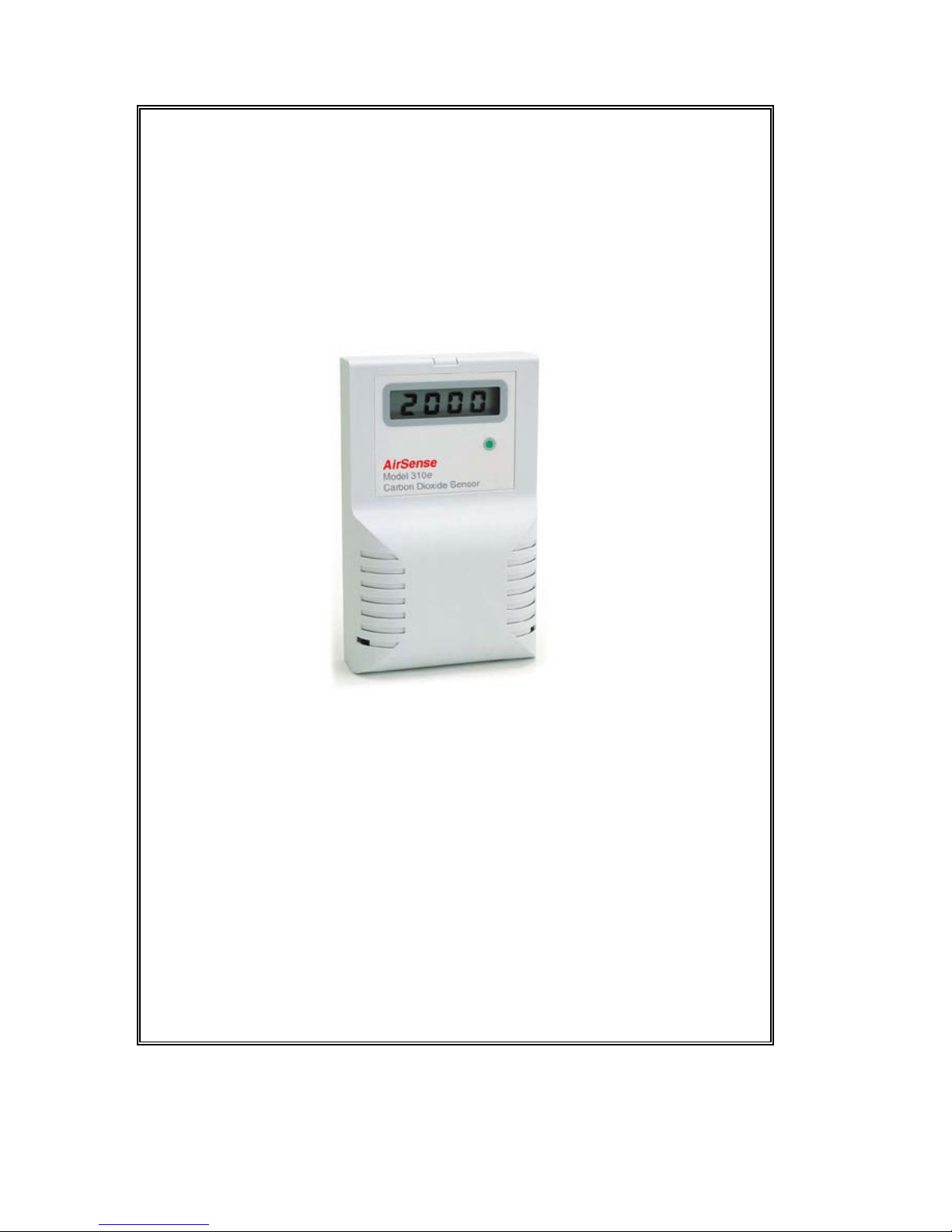
AIRSENSE
Model 310e
Microprocessor-based, Infrared
Environmental CO2 Sensor
Operator's manual
© Copyright 2010
Page 2

AirSense Model 310e Operator’s Manual
3/9/15 Digital Control Systems Page: i
Date
12/1/02
9/9/2005
10/7/08
12/7/10
(V6)
2/9/11
(V7)
3/9/15
(V8)
Page 3

AirSense Model 310e Operator’s Manual
Table of Contents
Introduction................................................................................. 1
Displays and Indicators ............................................................... 1
Specifications .............................................................................. 2
Installation................................................................................... 3
Cover Removal .....................................................................3
Mounting...............................................................................3
Wiring...................................................................................4
Power Supply...................................................................4
Signal Output ...................................................................4
Verifying Voltage or Current Output Connection ................5
Cover Replacement...............................................................6
Field Adjustments........................................................................ 7
Analog Output Range Adjustment........................................7
Altitude Correction ...............................................................9
Altitude Correction Procedure .........................................9
Calibration................................................................................. 10
Verification Procedure........................................................10
High CO2 Limit......................................................................... 11
Adjusting the High CO2 Limit............................................11
Optional High Limit Contact..................................................... 12
Setting High Limit Contact Polarity ...................................12
Duct Sampling Option............................................................... 13
Overview.............................................................................13
Duct Kit Contents ...............................................................14
Duct Kit Installation............................................................14
Disclaimers and Notices............................................................ 15
Safety Critical Applications................................................15
Limited Warranty and Remedies. .......................................15
3/9/15 Digital Control Systems Page: ii
Page 4

AirSense Model 310e Operator’s Manual
Introduction
The AirSense Model 310e is a non-dispersive infrared
analyzer for measuring environmental CO2 concentration in
ventilation systems and indoor living spaces. Its
measurement range of 0 - 5000 ppm (parts per million; 1000
ppm = 0.1%) covers the range required to monitor
compliance with ASHRAE or other ventilation efficiency
standards.
Packaged in a compact, distinctively styled enclosure, the
Model 310e can be discreetly installed anywhere from the
board room to the boiler room. Standard center wiring
access and fully floating outputs make installation a snap.
The Model 310e provides several output alternatives. A
voltage or 4 - 20 mA current output is standard. An optional
LCD readout is available. An optional relay contact can be
configured to open or close above a user-adjustable setpoint.
Terminals for connection to an optional thermistor are
available. With the correct thermistor installed A direct
temperature input can be provided to the controller.
A simple one-point calibration procedure and a built-in
calibration port that requires no special fittings or adapters
make the Model 310e simple to maintain.
Displays and Indicators
The basic Model 310e has a single green LED on the front
panel which illuminates whenever the unit is operating. This
LED is on steadily when the measured concentration is
below the high CO
2
limit, and blinks whenever the
concentration is above the limit.
The standard factory high limit is 1000 ppm, but can be
easily adjusted in the field. The procedure for adjusting the
high CO
2
limit is described on page 11.
The display option adds a 4 digit liquid crystal display
(LCD) to the front panel. The display shows the measured
CO2 concentration in parts per million (ppm). 1000 parts
per million equals 0.1%.
3/9/15 Digital Control Systems Page: 1
Page 5
AirSense Model 310e Operator’s Manual
Specifications
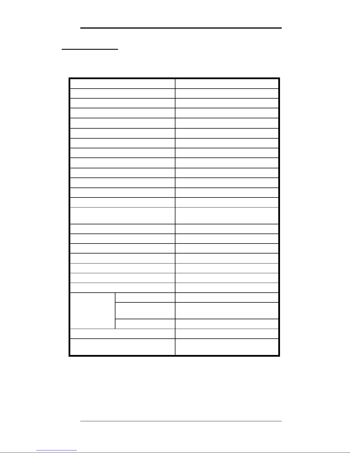
Operating principle Non-dispersive infrared (NDIR)
Gas sampling method Diffusion or sample draw
Measurement range 0 - 5000 ppm CO2
Typical drift (per year)
±75 ppm (@ 1200ppm)
Accuracy
±5% of reading or ±75 ppm,
Repeatability
±20 ppm
Recommended Calibration Interval Five Years
Response time Less than 1 minute
Operating temperature range
0 to 50 ° C
Operating humidity range 0 - 90% RH (non condensing)
Storage temperature
-30 to + 60 ° C
Power requirements 20 - 28 VRMS AC, 18 - 30 VDC
Power consumption Less than 2W @ 24 VAC
Calibration adjustments Span only (offset electronically
nulled)
Calibration verification time 10 minutes typical
Dimensions 5.2" x 3.2" x 1.4"
Voltage output (linear) 0 - 10 volts DC standard
Current output (linear)
4 - 20 mA (R
L
≤ 500Ω)
Warm-up time 3 minutes
Weight 6.5 Oz. (.35 Kg)
Optional Digital Display 4 digit, .35" LCD
Optional setpoint range 0 to full scale
High
Limit
contact polarity jumper selectable
Contact contact rating 2A @ 24 VAC
Operating life expectancy 10 years typical
Warranty 18 months, parts and labor through
repair or exchange
3/9/15 Digital Control Systems Page: 2
Page 6
AirSense Model 310e Operator’s Manual
Installation
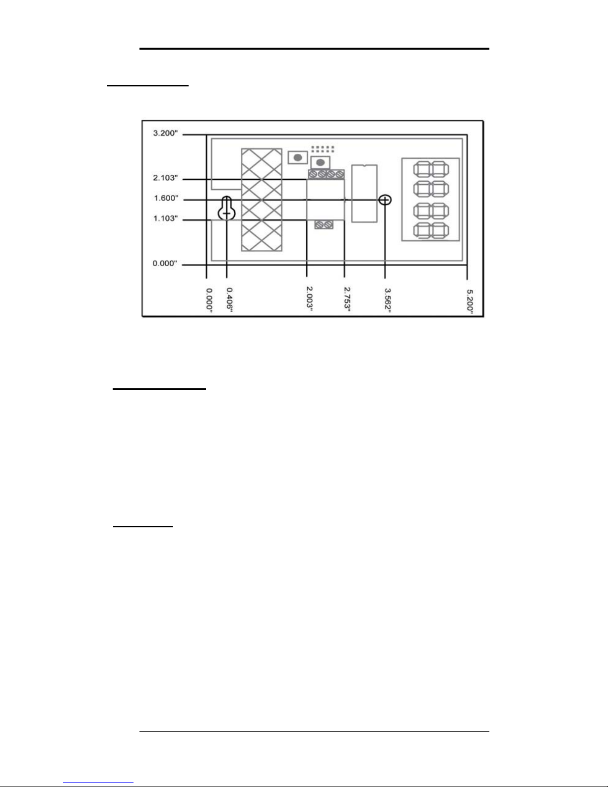
Figure 1: AirSense Model 310e Mounting Dimensions
Cover Removal
To open the Model 310e use a coin in the slot on the bottom
to release the snap. Lift the cover up slightly to disengage
the closure and remove cover with a downward motion to
clear the catch at the top of the unit.
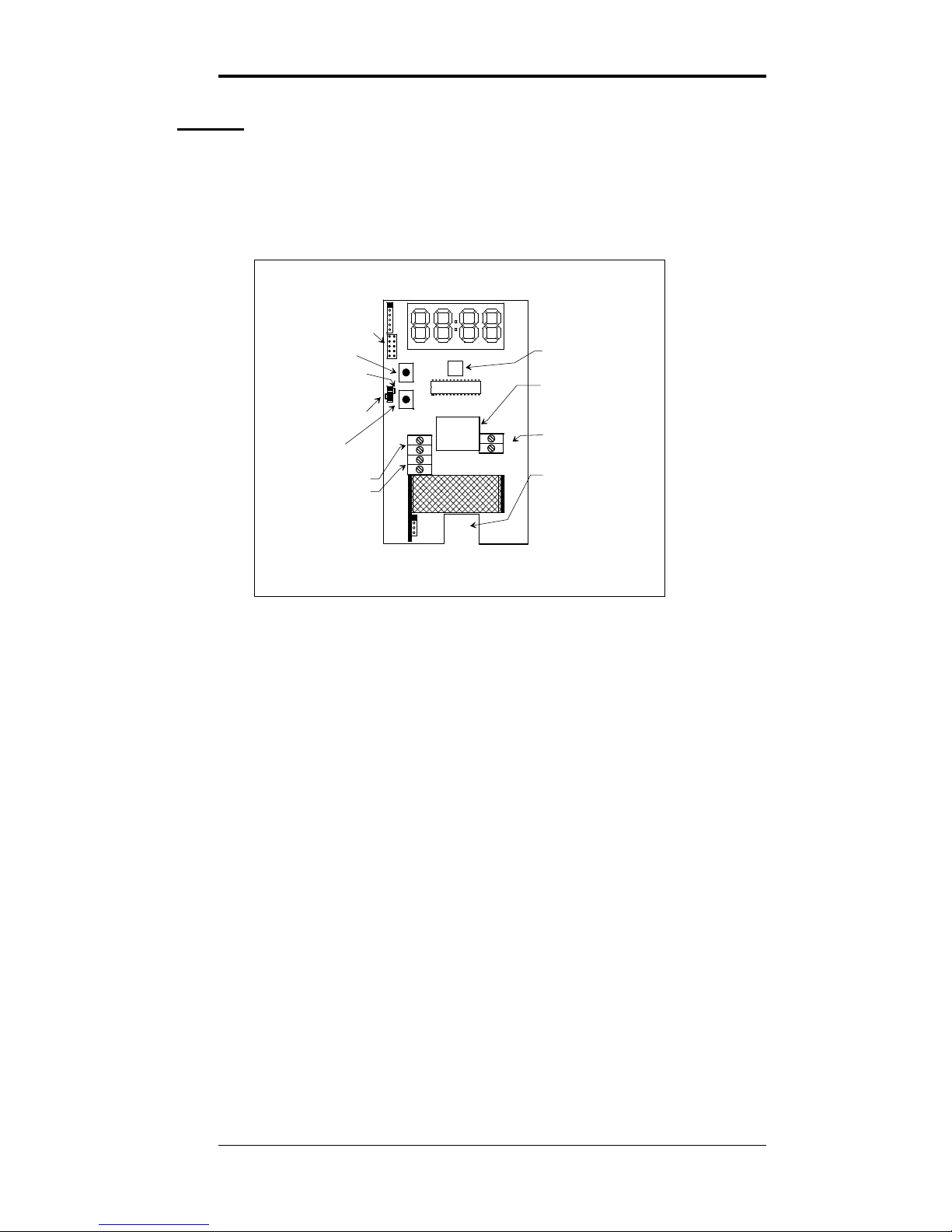
The locations of controls and terminals on the main circuit
board are shown in the Figure 2 on page 4.
Mounting
The Model 310e is designed for flush mounting with two
fasteners. The locations of the mounting points (shown in
Figure 1) allow direct mounting on a standard simplex
(single circuit) junction box. There is a wiring cutout in the
center of the unit near the terminal strips.
3/9/15 Digital Control Systems Page: 3
Page 7
AirSense Model 310e Operator’s Manual
Wiring
This section describes the external connections to the Model
310e. Wiring enters the chassis through the cutout in the
center of the unit.
SHORTING BLOCK HERE
FOR VOLTAGE OUTPUT
USER
JUMPERS
UP
BUTTON
DOWN
BUTTON
ANALOG OUTPUT
SELECTOR
RELAY CONNECTION
SHORTING BLOCK HERE
FOR CURRENT OUTPUT
UPPER MOUNTING
SCREW ACCESS
ANALOG OUTPUT
+
OUT
-
DIS1
J3
JP3
JP2
JP1
JP4
JP5
+
-
WIRING
ACCESS
POWER IN
(POLARITY MATTERS
FOR DC INPUT ONLY)
LOWER MOUNTING
SCREW ACCESS
MICROPROCESSOR
J4
J5
POWER
J8
+
-
DN
UP
Figure 2: Model 310e Component Locations
Power Supply
The Model 310e will operate from an AC or DC input
voltage between the values called out in the specifications on
page 2. The power supply leads are connected to the twoterminal power connector shown in Figure 2.
The model 310e must never be connected directly to line
power. Operation at voltages higher than specified will
damage the unit and void the warranty.
When operating from DC power, the polarity of the power
leads must be as shown in Figure 2. Reversed polarity
connection will not damage the unit, but will make it
inoperable until the connection is reversed.
Signal Output
The Model 310e provides either a 0 - 10 volt or a 4 - 20 mA
current loop output at the two terminals of the analog output
connector shown in Figure 2.
3/9/15 Digital Control Systems Page: 4
Page 8

AirSense Model 310e Operator’s Manual
The type of analog output is determined by the setting of the
analog output selector shown in Figure 2.
The analog output of the Model 310e is completely isolated
from the power supply. The common outputs of multiple
units can be connected together with no interaction
regardless of power supply hook-up.
Voltage
When the outboard and middle pins of the analog output
selector are connected with the shorting block, a voltage
output appears between the two terminals marked ANALOG
OUTPUT. The output voltage increases linearly from 0
volts at the low output threshold to 10 volts at the high
output threshold. The unit is shipped from the factory with
the low output threshold at 0 ppm and the high output
threshold at 2000 ppm. See the Analog Output Range
Adjustment section on page 7 to change the analog output
range limits.
Current
When the inboard and middle pins of the analog output
selector are connected with the shorting block, a current
output appears between the two terminals marked ANALOG
OUTPUT. The output current increases linearly from 4 mA
at the low output threshold to 20 mA at the high output
threshold. The unit is shipped from the factory with the low
output threshold at 0 ppm and the high output threshold at
2000 ppm. See the Analog Output Range Adjustment section
on page 7 to change the analog output range limits.
If the total resistance between the two terminals exceeds the
specified maximum loop resistance, the output current may
be erroneously low at high concentrations.
Verifying Voltage or Current Output Connection
After the voltage or current output of the Model 310e is
connected to a controller or indicator, the following check
should be performed to ensure that the connection has been
properly established and the Model 310e is transmitting the
correct values:
3/9/15 Digital Control Systems Page: 5
Page 9

AirSense Model 310e Operator’s Manual
1. Be sure that the output select jumper is set correctly
for voltage or current output. If this is not done first,
the following check may produce incorrect results.
Note whether the shorting block at jumper JP5 is
covering both pins or only a single pin, then borrow
the shorting block and slide it over the two pins of
jumper JP4 (see Figure 2). The display (if present) will
show ‘SEL’
2. Momentarily closing JP5 will set the unit to full scale
output (10V or 20mA). Do not press the buttons on the
unit as this will affect the output calibration.
If the receiving device does not indicate a full scale
reading after JP5 is closed, verify that the wiring is
correct.
3. Remove the shorting block from JP4 and restore it to its
original position at jumper JP5. The Model 310e will
reset and it’s output now corresponds to the actual
detected CO2 concentration.
Cover Replacement
Engage the top center of the cover under the latch at the top
of the base, then press the bottom of the cover onto the base
until it latches.
3/9/15 Digital Control Systems Page: 6
Page 10
AirSense Model 310e Operator’s Manual
Field Adjustments
This section describes the features that can be field
configured and the procedures to make these changes.
Analog Output Range Adjustment
This section refers to advanced features of the Model 310e.
2000 ppm users need not perform this adjustment.
The Model 310e ships from the factory set for an analog
output range of 0 to 2000 ppm. This range can be changed
to any sub-range between 0 and 5000 ppm by changing two
parameters:
The low output threshold is the concentration at which
the analog output will begin to rise. The factory default
low output threshold value is 0.
The high output threshold is the concentration at which
the analog output reaches its maximum value. The
factory default high output threshold value is 2000.
For example, a particular application may require the analog
output to remain at 0V or 4.0 mA until the gas concentration
reaches 500 ppm, then reach 10V or 20 mA at a
concentration of 1000 ppm. In this example the analog
output would scale across this 500 ppm sub-range so that the
analog output would be at half scale (5V or 12 mA) at
750 ppm.
To change the analog output range use the following
procedure:
1. Note whether the shorting block at jumper JP5 is
covering both pins or only a single pin, then borrow
the shorting block and slide it over the two pins of
jumper JP4 (see
Figure 2 on page 4). The display (if
present) will show ‘SEL’.
2. The display (if present) will show ‘SEL’.
Momentarily closing a jumper selects which value to
change. If the wrong jumper is selected simply open
JP4 to restart the unit and begin again.
3/9/15 Digital Control Systems Page: 7
Page 11

AirSense Model 310e Operator’s Manual
3. Select the low output threshold by momentarily
closing JP1.
If the display is present it will show the current low
display threshold. If there is no display the value can
be displayed using a meter connected to the analog
output. In this calibration mode the analog output is
10,000 ppm at full scale (i.e. 10.0 volts or 20.0 mA).
If the voltage output is selected, this scaling
corresponds to 1 ppm per millivolt or 1000 ppm per
volt.
4. Use the ‘UP’ and ‘DOWN’ buttons to adjust the low
output threshold to the desired value. In the example
this would be set to 500.
5. Remove the shorting block from JP4 to save the
value; the unit will reset itself.
6. Reconnect JP4. The display (if present) will show
‘SEL’. Select the high output threshold by
momentarily closing JP2.
If present, the display will show the high output
threshold. If there is no display use a volt meter as
described in step 3.
7. Use the ‘UP’ and ‘DOWN’ buttons to adjust the high
output threshold to the desired value. In the example
this would be set to 1000.
8. Remove the shorting block from JP4 and restore it to
its original position at jumper JP5. The Model 310e
will reset and its output will now only change when
the gas concentration is within the range selected.
Below this range the output remains low, above this
range the output remains high.
3/9/15 Digital Control Systems Page: 8
Page 12
AirSense Model 310e Operator’s Manual
Altitude Correction
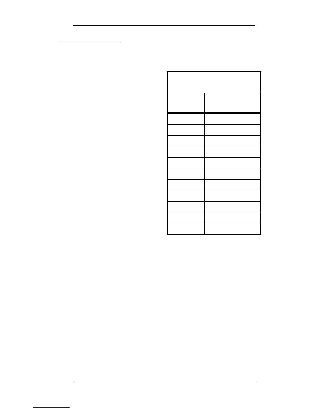
The Model 310e is factory-calibrated for operation at sea
level. When operated at higher elevations, the calibration
must be adjusted by the
amount shown in the altitude
correction table to the right.
ALTITUDE
CORRECTION TABLE
Altitude
[feet]
Multiplication
Factor
Altitude Correction Procedure
To adjust the calibration of a
unit currently calibrated for
sea level operation to a new
altitude proceed as follows:
0 1.0
500 1.02
1000 1.03
1. Let the Model 310e
stabilize to the ambient
CO2 concentration, and
record the reading in
ppm.
1500 1.05
2000 1.07
2500 1.08
3000 1.10
2. Multiply the reading by
the scale factor
corresponding to the
operating altitude in the
altitude correction table.
3500 1.12
4000 1.14
4500 1.16
For instance if the unit is
operating at an altitude of 4000 ft, the scale factor from
the table is 1.14. If the concentration reads 420 ppm,
multiply 420 times 1.14 giving 478 ppm. Adjust the
display to read 480.
5000 1.18
3. Remove the Model 310e’s cover (see cover removal
procedure on page 3).
4. Note whether the shorting block at jumper JP5 is
covering both pins or only a single pin, then borrow the
shorting block and slide it over the two pins of jumper
JP2 (see Figure 2 on page 4). Use the 'UP' and 'DOWN'
buttons to change the concentration to the value just
calculated.
3/9/15 Digital Control Systems Page: 9
Page 13

AirSense Model 310e Operator’s Manual
5. Remove the shorting block from jumper JP2 and return it
to its previous position over one or both pins of jumper
JP5.
6. Replace the cover (see procedure on page 6).
Calibration
This section describes the calibration verification procedure
and calibration adjustment procedures.
Verification Procedure
A quick but approximate calibration verification can be done
by supplying the unit with outside air and letting the reading
stabilize. CO2 concentrations in outside air are typically
between 375 and 450 ppm.
A more accurate calibration check requires the use of
calibration gas of known concentration. 2000 ppm
calibration gas is recommended A calibration kit is available
from the factory.
To verify the Model 310e's calibration, proceed as follows:
1. Remove the front cover of the unit (see procedure on
page 3).
2. If there is no display on the unit being calibrated, connect
a current or volt meter to the analog output terminals.
Check the setting of the analog output selector (see
Figure 2 on page 4) to determine whether the unit is set
for voltage or current output.
3. Remove the dust cover from the calibration nipple, attach
a flexible tube and establish a flow of between 50 and
100 cc/min (0.002 to 0.004 SCFM) of calibration gas
through the sensor. Allow approximately two minutes
for the reading to stabilize.
4. If the reading differs by less than ± 50 ppm from the
known concentration of the calibration gas, no adjustment
is recommended; proceed directly to step 7.
Otherwise note whether the shorting block at jumper
JP5 is covering both pins or only a single pin, then
3/9/15 Digital Control Systems Page: 10
Page 14

AirSense Model 310e Operator’s Manual
borrow the shorting block and slide it over both pins of
jumper JP2 (see Figure 2 on page 4).
5. Use the 'UP' and 'DOWN' buttons (see Figure 2 on page
4) to adjust the reading.
6. When the reading agrees with the concentration of the
calibration gas, remove the shorting block on jumper JP2,
and replace in its original position at jumper JP5.
7. Turn off the calibration gas flow, disconnect the gas
tubing from the calibration nipple and replace its dust
cover. Remove the meter leads from the terminal strip
and replace the front cover (see procedure on page 6).
High CO2 Limit
An adjustable high CO2 limit is a standard feature of the
model 310e. The front panel LED changes from steady to
blinking when the indicated concentration is above the high
CO
2
limit value. An optional contact closure is available
which opens or closes when the high limit is exceeded.
Adjusting the High CO
2
Limit
The setpoint value is adjusted by closing jumper JP3 (see
Figure 2 on page 4). If the display is present when JP3 is
closed it will show the current high limit setpoint in ppm
CO
2
.
If there is no display this setting can be adjusted by using a
meter connected to the output. In this calibration mode the
analog output is 10,000 ppm at full scale (i.e. 10.0 volts or
20.0 mA). If the voltage output is selected, this scaling
corresponds to 1ppm per millivolt or 1 volt per 1000 ppm.
The setpoint is adjusted with the ‘UP’ and ‘DOWN’ buttons
while JP3 is closed. When JP3 is opened, the new relay
setpoint takes effect and is stored in non-volatile memory.
The setpoint hysteresis is approximately 40 ppm.
3/9/15 Digital Control Systems Page: 11
Page 15
AirSense Model 310e Operator’s Manual
Optional High Limit Contact
The high CO2 limit option provides a dry (i.e. unpowered)
contact closure that activates when the detected
concentration rises above the high CO
2
limit. The high limit
is adjustable from 0 to full scale of the unit
Setting High Limit Contact Polarity
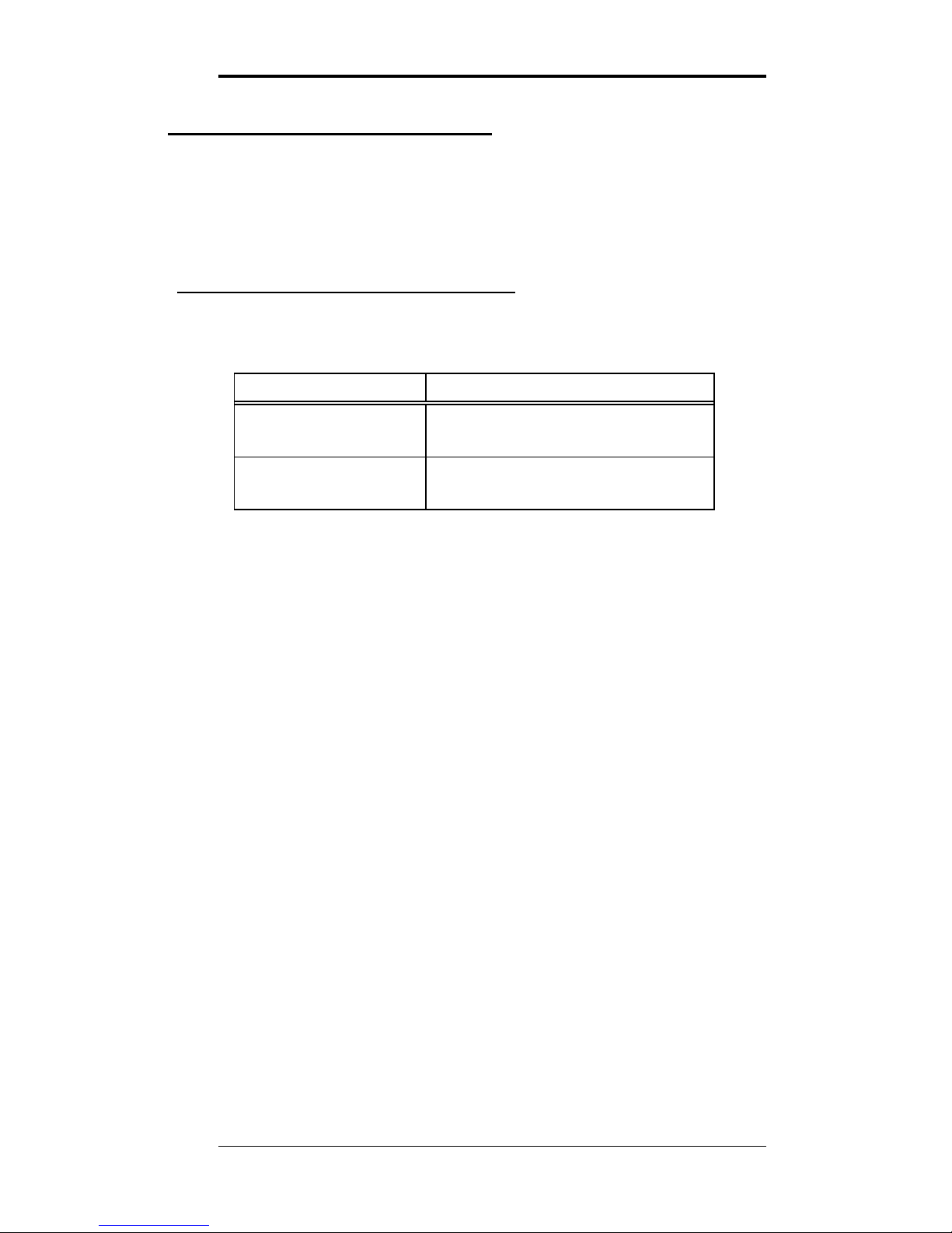
The polarity of the high limit contact is set with jumper JP5
as shown in the table below.
Jumper JP5 Relay Operation
OPEN normally closed
opens above setpoint
CLOSED
(factory default)
normally open
closes above setpoint
To open jumper JP5 remove the shorting block from the two
pins, and replace it so that it engages only a single pin of the
jumper. The shorting block should not be removed; it is
required during the calibration procedure.
3/9/15 Digital Control Systems Page: 12
Page 16
AirSense Model 310e Operator’s Manual
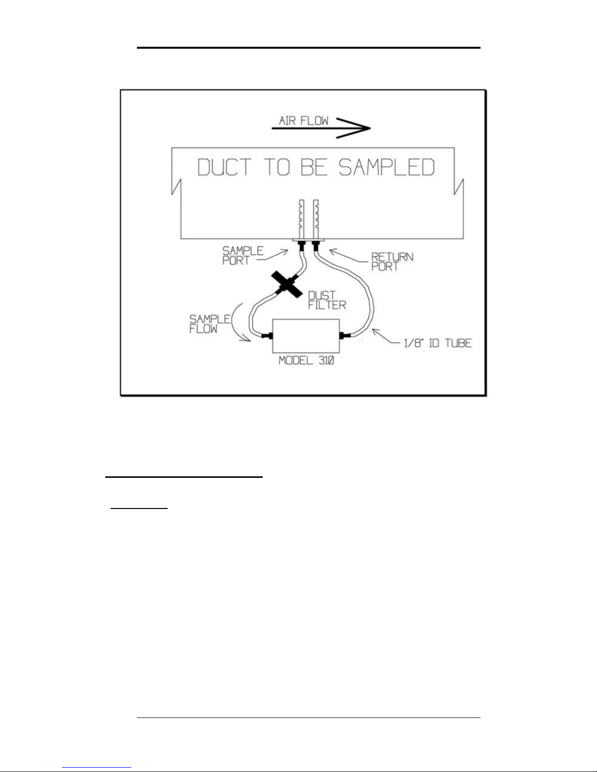
Figure 3: Duct Sampling Schematic
Duct Sampling Option
Overview
The duct sampling option is used to divert a portion of the
duct airflow through the Model 310e. The difference
between the total pressure at the upstream sample port and
the static pressure at the downstream return port propels the
sample stream. Minimum recommended flow rate is 200
feet per minute.
A Model 310e with the duct sample option has a sample
draw adapter fitted to the bottom of its enclosure. The duct
probe assembly is connected to tubing nipples on the
adapter.
3/9/15 Digital Control Systems Page: 13
Page 17
AirSense Model 310e Operator’s Manual
Duct Kit Contents
1 dust filter 2 sheet metal screws
1 duct probe assembly 2 lengths of 1/8” ID tubing
Duct Kit Installation
1) Select a point along the duct where the probe assembly can
be installed into unrestricted airflow without interfering with
any internal duct components such as dampers, radiators, etc.
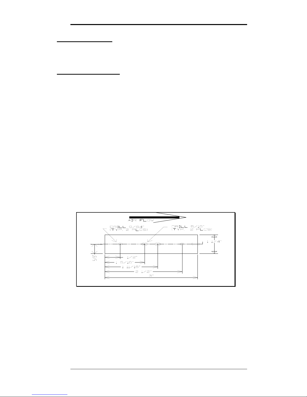
2) Mark and drill the four holes for the duct probe as shown in
Figure 4. The centerline must be parallel to the air flow
through the duct.
3) Install the duct probe assembly through the holes just drilled.
The sample port must be on the upstream side. Secure
the probe assembly in place with the two sheet metal screws.
4) Connect the open ends of the two tubes from the probe
assembly to the two sample ports on the base of the Model
310e. It makes no difference which tube is connected to
which port on the Model 310.
Figure 4: Duct Probe Installation Dimensions
3/9/15 Digital Control Systems Page: 14
Page 18

AirSense Model 310e Operator’s Manual
Disclaimers and Notices
Safety Critical Applications
DCS products are not designed, intended or authorized for
use in life safety systems or devices where failure of the
Model 310e to perform to specification may be reasonably
expected to result in significant risk of injury or death.
Limited Warranty and Remedies.
DCS warrants to Buyer of the AirSense Model 310e that for
18 months from the date of shipment of Products to the
Buyer that Products will substantially conform with the
product specifications agreed to by DCS. This warranty is
not transferable.
This warranty does not cover:
Defects due to misuse, abuse, or improper or inadequate
care, service or repair of Products;
Defects due to modification of Products, or due to
alteration or repair by anyone other than DCS; or
Problems that arise from lack of compatibility between
DCS’ Products and other components used with those
Products or the design of the product into which
Products are incorporated. Buyer is solely responsible
for determining whether Products are appropriate for
Buyer's purpose, and for ensuring that any product into
which Products are incorporated, other components used
with DCS’ Products, and the purposes for which DCS’
Products are used are appropriate and compatible with
those Products.
3/9/15 Digital Control Systems Page: 15
Page 19

AirSense Model 310e Operator’s Manual
THE WARRANTY IN THIS SECTION IS IN LIEU OF
ALL OTHER WARRANTIES, EXPRESS OR IMPLIED.
DCS EXPRESSLY DISCLAIMS ALL IMPLIED
WARRANTIES, INCLUDING THE WARRANTIES OF
MERCHANTABILITY AND FITNESS FOR A
PARTICULAR PURPOSE. DCS IS NOT RESPONSIBLE
IN ANY WAY FOR DAMAGE TO A PRODUCT,
PROPERTY DAMAGE OR PHYSICAL INJURY
RESULTING IN WHOLE OR IN PART FROM (1)
IMPROPER OR CARELESS USE, (2) UNAUTHORIZED
MODIFICATIONS, OR (3) OTHER CAUSES BEYOND
DCS’ CONTROL. IN NO EVENT IS DCS LIABLE TO
THE BUYER OR ANY OTHER PERSON FOR COST OF
PROCUREMENT OF SUBSTITUTE GOODS, LOSS OF
PROFITS, OR FOR ANY OTHER SPECIAL,
INCIDENTAL OR CONSEQUENTIAL DAMAGES.
To obtain service under this warranty, unless DCS agrees
otherwise, Buyer must obtain a returned material
authorization (RMA) number from the factory, pack any
nonconforming Product carefully, and ship it, postpaid or
freight prepaid, to the address provided when the RMA
number is issued. Buyer must include a brief description of
the nonconformity. Any actions for breach of this warranty
must be brought within six months of the expiration of this
warranty.
If DCS determines that a returned Product does not conform
to the warranty in this section, it will either repair or replace
that Product, at DCS’ discretion, and will ship the Product
back to Buyer free of charge. At DCS’ option, DCS may
choose to refund to Buyer the purchase price for a
nonconforming Product instead of repairing or replacing it.
Units returned for service under this warranty and
determined on examination to be operating properly are
subject to a service charge.
3/9/15 Digital Control Systems Page: 16
Page 20

 Loading...