

Air-rite 2581 User Manual
2581
ride-rite.com
INSTALLATION INSTRUCTIONS
08-15
IMPORTANT
PLEASE DON’T HURT YOURSELF, THE KIT, OR YOUR VEHICLE. TAKE A MINUTE TO READ THIS IMPORTANT INFORMATION.
SAFE INSTALLATION
Please take all safety precautions during installation. A hydraulic jack can fail, and if that happens, you can be
seriously hurt, or worse, if you are relying on it to hold up the vehicle. If you use a hydraulic jack, secure jack
stands in the appropriate locations and chock any tires still touching the ground.
Wear safety glasses or goggles. Your eyes may be lower than some parts and pieces, and you don’t want to lose an eye.
Remove the possibility of any electrical issues by disconnecting the negative battery cable.
VEHICLE GVWR
NEVER exceed the maximum load recommended by the vehicle manufacturer (GVWR). The GVWR can be found
in your vehicle’s Owner’s Manual or on the data plate on the driver’s side door.
PRESSURE TO LOAD
Be sure to review the load limits noted in the Air Spring Kit Installation Instructions (sold separately).
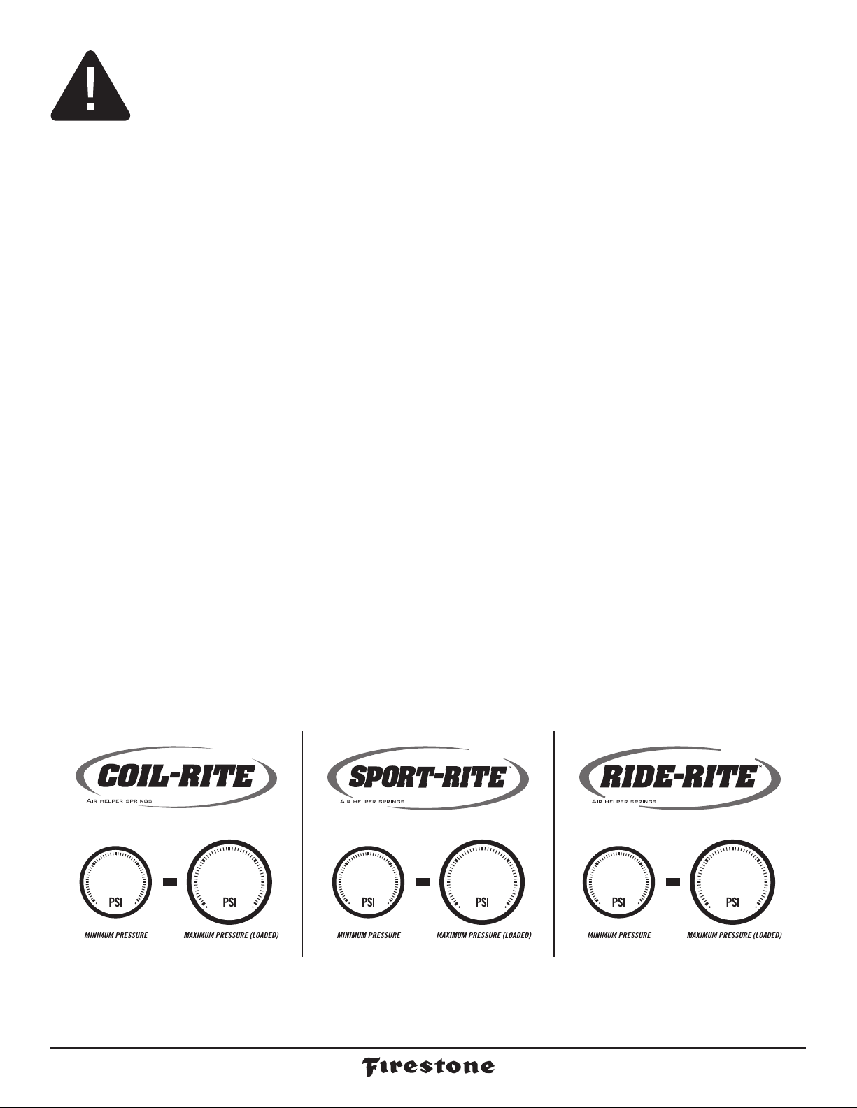
APPROPRIATE AIR PRESSURE
For best ride, use only enough air pressure in the Air Springs to level the vehicle when viewed from the
side (front to rear). This will vary, depending on the load, location of the load, condition of the existing
suspension, and personal preference.
ONCE INSTALLED SUCCESSFULLY, FOLLOW THE PRESSURE REQUIREMENTS FOR THE AIR SPRINGS.
FOR FIRESTONE, GENERALLY:
305 100510010
ride-rite.com1
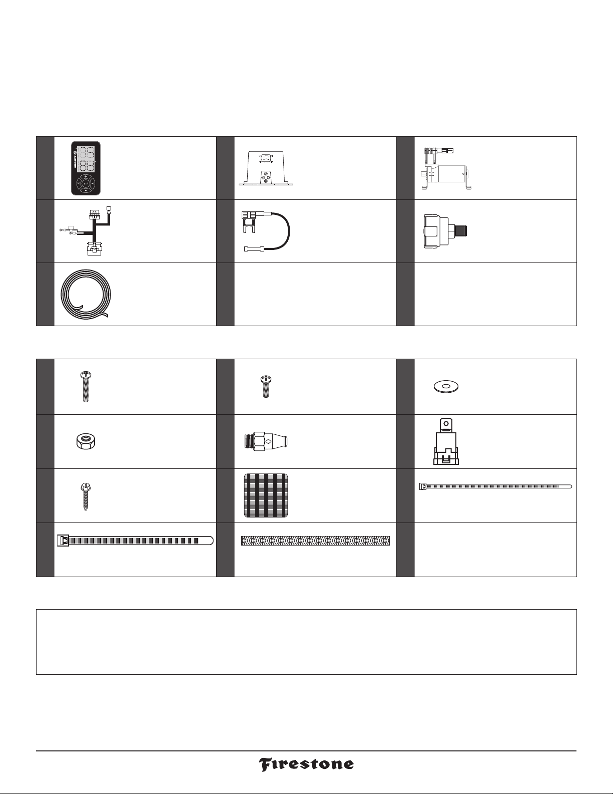
PARTS AND TOOLS
Compare the parts below to your kit. Assure you have all pieces, and organize them for an easier installation.
MAIN KIT CONTENTS
WIRELESS
PART # 9490
x 1
CONTROLLER
PART # 9489
EXH
EXH
AS-1 AS-2
AS-1 AS-2
SUP
SUP
x 1 ECU
x 1 AIR COMPRESSOR
PART # 9377
x 1 WIRE HARNESS
PART # 9491
AIR LINE TUBE
x 1
(18 FEET)
PART # 9414
A21-760-2581 HARDWARE PACK
10-32 x 1"
x 4
MACHINE SCREW
PART # 3087
x 9 10-32 NYLOCK NUT
PART # 3088
10-16 x 3/4"
x 1
SELF-TAPPING
PART # 3421
SCREW
PART # 2526
PART # 3093
PART # 3055
PART # 9275
IGNITION
x 1
FUSE TAP
10-32 x 3/4"
x 3
MACHINE SCREW
1/8 NPT PUSH-
x 1
TO-CONNECT
STRAIGHT FITTING
x 4 VELCRO TABS
PART # 9129
PART # 3086
PART # 9361
PART # 9036
x 1 AIR FILTER
x 13 3/16" FLAT WASHER
x 1 SEALED RELAY
x 15 RED NYLON TIE
PART # 9488
x 4 LARGE NYLON TIE x 2 THERMAL SLEEVE
PART # 0899
TOOLS REQUIRED:
3/16" DRILL BIT
WIRE CRIMPER/STRIPPER
PHILLIPS SCREW DRIVER
(2) 7/16" WRENCHES OR SOCKETS
POWER DRILL
ELECTRICAL TAPE
9/16" WRENCH
2581 Installation Instructions 2
PLIERS
UTILITY KNIFE
CENTER PUNCH OR MARKING TOOL
CONTENTS AND OVERVIEW
PAGE
PAGE
PAGE
PAGE
PAGE
PAGE
PAGE
PAGE
PLANNING THE
INSTALL
4
PREPARE THE AIR
COMPRESSOR
5
DRILL HOLES FOR
AIR COMPRESSOR
6
AND ECU
INSTALL THE
AIR COMPRESSOR
7
AND ECU
INSTALL THE
WIRE HARNESS
8
INSTALL THE
AIR LINE TUBES
9
INSTALL THE
AIR FILTER AND
10
CLEAN UP
ADJUSTING AIR
PRESSURE AND
11
UNITS
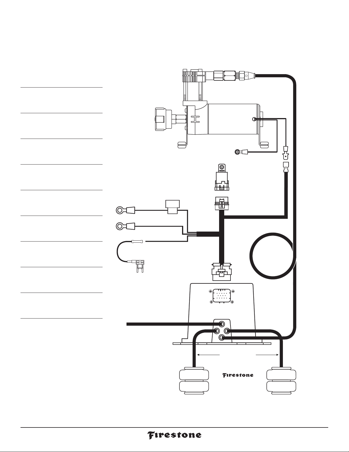
AIR FILTER
RED (+)
BATTERY (+)
BLACK (-)
BATTERY (-)
20 AMP FUSE
YELLOW
+12V IGN
1/8 NPT PUSH-TO-CONNECT
STRAIGHT FITTING
AIR COMPRESSOR
SEALED
RELAY
RELAY
CONNECTOR
WIRE
HARNESS
BLACK
(GROUND)
RED/WHITE
(COMPRESSOR +)
Create
loop in Air
Line Tube.
* As a water/debris
trap. See page 4.
RED (+)
PAGE
PAGE
PAGE
WIRELESS CONTROLLER
MEMORY SETTINGS
12
AND ERROR CODES
TEST THE SYSTEM
13
FIX AN AIR LEAK
14
OPTIONAL: Use supplied
Fuse Tap. See important
information on the Using
the Fuse Tap sheet.
AIR LINE TUBE
OPTIONAL: Install
Air Line Tube to
EXH air fitting.
See page 9 for
important information.
LEFT AIR SPRING
(when facing forward)
ECU
CONNECTOR
ECU
EXH
EXH
AS-1 AS-2
AS-1 AS-2
SUP
SUP
AIR LINE TUBE
AIR SPRINGS
(sold separately)
AIR LINE
TUBE
RIGHT AIR SPRING
(when facing forward)
ride-rite.com3

PLANNING THE INSTALL
THESE PLANNING STEPS WILL HELP YOU SAVE TIME AND WILL MAKE THE INSTALLATION EASIER.
DETERMINE THE MOUNTING LOCATION FOR THE AIR COMPRESSOR
- Provides ample air flow and is protected from airborne debris and moisture.
- Mount close enough to the ECU to allow Wire Harness connections to reach.
- If using the optional Firestone Air Accessory Mounting Kit, consider the
guidelines above, and follow the kit’s instructions.
DETERMINE THE MOUNTING LOCATION FOR THE ECU
- Mount close enough to the Air Compressor to allow Wire Harness
connections to reach.
- Allow room for Air Line Tubes to connect to the air fittings on the ECU.
- Allow room for the 14-pin ECU connector to connect to the ECU.
- Allow room for the Air Line Tube to run without sharp curves or bends.
- Using supplied fasteners shown in Step 3 is recommended. If no other mounting option is available,
see the sidebar on Step 2 for using the Large Nylon Ties.
- Select a location that is solid and secure on the body or frame of the vehicle, away from any moving parts,
electrical or any other lines.
PLAN INSTALLATION ROUTES FOR WIRING AND AIR LINES
- Make sure the Wire Harness and Air Line Tubes are not exposed to sharp metal edges that can damage them.
- Use supplied Thermal Sleeves on Air Line Tubes when routing near heat sources.
- Use supplied Nylon Ties to secure Air Line Tubes and Wire Harness to the vehicle.
- Make a loop in the Air Line Tube where shown. This creates a water/debris trap that protects the Air Compressor.
- Measure twice, cut once!
AS-1 AS-2
AS-1 AS-2
EXH
EXH
SUP
SUP
TAPE ALL ELECTRICAL CONNECTIONS
- Use electrical tape to appropriately secure and protect all electrical connections.
USING PUSH-TO-CONNECT FITTINGS FOR AIR LINES
Your kit includes Push-to-Connect fittings to connect the Air Line Tubes to hardware.
Use the instructions below when using the Air Line Tubes.
Insert end of Air
Line Tube into
1
air fitting.
Push Air Line Tube
into air fitting as
2
far as possible.
Gently pull on
the Air Line Tube
3
to check for a
secure fit.
To remove, push
down collar and
4
gently pull Air Line
Tube away.
Removal Tip: Use a 1/4”, 5/16”,
or 6mm open-ended wrench
to push the collar down.
2581 Installation Instructions 4
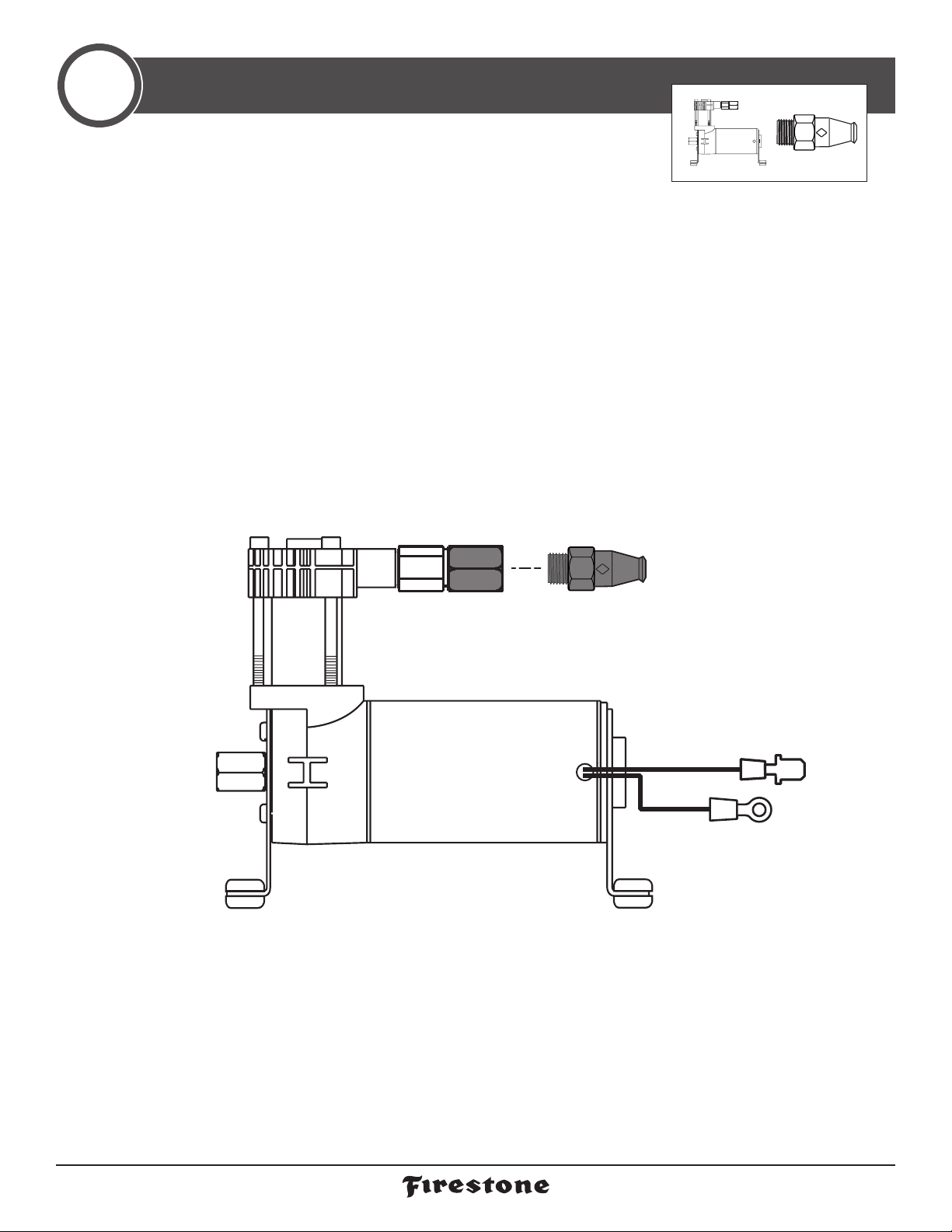
PREPARE THE AIR COMPRESSOR
1
Note that the Air Compressor can be mounted facing any direction.
Install 1/8 NPT Push-toConnect Straight Fitting
1
on the Check Valve.
PRE-INSTALLED
CHECK VALVE
1/8 NPT PUSH-TO-CONNECT
STRAIGHT FITTING
Tighten to engage two threads
of thread lock.
AIR COMPRESSOR
ride-rite.com5
 Loading...