

Page 1

Page 1 of 33
Optimus-1 EX - FTS
Mast Assembly
Procedure
07-05-2019
OPT1-M-104
Rev.01
Page 2

OPT1-M-104 Rev.01 Optimus-1 EX - FTS Mast Assembly Procedure
Page 2 of 33
This document has been prepared for the exclusive use of Airobotics Ltd. (“Airobotics”) under the
direction and authority of Airobotics and shall, at all times, remain the property of Airobotics. The
holder hereof acknowledges and agrees that this document contains or may contain trade secrets,
copyrighted material and commercial and proprietary information, privileged and confidential, and the
holder hereof further agrees that this document may not be reproduced, distributed or copied, in whole
or in part, without the express prior written consent of Airobotics. In the event this manual is sold or
distributed to any other party, no warranty or guarantee, expressed or implied, is made as to the
accuracy, sufficiency or suitability of the materials contained herein or of any revision, supplement or
bulletin hereto, and Airobotics shall not be responsible for providing revisions for this manual to any
third-party to whom this document is sold or distributed to. It is understood and agreed to by such
other party that it shall release, indemnify, and hold Airobotics, its officers, employees and agents
harmless against any and all claims or actions of whatever nature which may arise or claim to arise
from the use hereof.
Page 3
OPT1-M-104 Rev.01 Optimus-1 EX - FTS Mast Assembly Procedure
Page 3 of 33
Table of Contents
1.1 Abbreviations ............................................................................................................................................. 6
1.2 Applicable Documents ............................................................................................................................. 6
2.1 About this Document ............................................................................................................................... 7
2.2 About the FTS ............................................................................................................................................ 7
3.1 The Location .............................................................................................................................................. 8
3.2 FTS Mast Unit Parts List .......................................................................................................................... 9
3.3 Preparing the Antennas for Assembly ............................................................................................... 10
3.3.1 Preparing the Main Antenna for Assembly .................................................................................. 10
3.3.2 Preparing the Taoglass Antennas for Assembly .......................................................................... 11
3.4 Mounting the Antennas on the Mast .................................................................................................. 12
3.5 Mounting the FTS Unit Box on the Mast ............................................................................................ 13
4.1 SIM Card Installation .............................................................................................................................. 15
4.2 Battery Installation .................................................................................................................................. 18
4.3 FTS Electrical Assembly ........................................................................................................................ 21
4.3.1 Connecting the Antenna Electrical Cables .................................................................................... 21
4.4 DC Electrical Panel Modifications ........................................................................................................ 24
4.4.1 Disconnecting Wires and Cables ..................................................................................................... 25
4.4.2 Installing POE Injector ....................................................................................................................... 28
Page 4

OPT1-M-104 Rev.01 Optimus-1 EX - FTS Mast Assembly Procedure
Page 4 of 33
Table of Figures
Figure 1 The FTS Mast Unit box, mounted on the upper mast ......................................................................... 8
Figure 2 FTS Main Antenna bracket mounting ................................................................................................. 10
Figure 3 Taoglass RF antennas bracket mounting ........................................................................................... 11
Figure 4 Connecting the V-bracket sub-assemblies to the mast .................................................................... 12
Figure 5 The location of the FTS Mast Unit cabinet on the mast ................................................................... 13
Figure 6 Attach the hold hanging (metal pole clamp) brackets to the mast ................................................ 14
Figure 7 Attach the plate holders to the brackets and cabinet back ............................................................. 14
Figure 8 Open the lid of the FTS mast unit box .................................................................................................. 15
Figure 9 Open the lid of the RV50 cellular modem box .................................................................................... 16
Figure 10 The SIM Card holder lid ......................................................................................................................... 16
Figure 11 The orientation of the SIM cards in the SIM Card holder ............................................................... 17
Figure 12 The battery holder and its 4 screws ................................................................................................... 18
Figure 13 The battery socket ................................................................................................................................. 19
Figure 14 The Power LEDs ..................................................................................................................................... 19
Figure 15 Antenna types ......................................................................................................................................... 21
Figure 16 Cable connections in the FTS mast unit back panel ....................................................................... 22
Figure 17 The FTS mast unit back panel ............................................................................................................. 22
Figure 18 The mast unit interfaces cover panel ................................................................................................. 23
Figure 19 The mast unit interfaces panel ............................................................................................................ 23
Figure 20 The Mast main power switch .............................................................................................................. 24
Figure 21 The LAN cable from MOXA Port 4 (POE) to the 2SP4 module ...................................................... 25
Figure 22 The wire connecting the 2J4 connector to the 2F17 fuse ............................................................. 26
Figure 23 Electrical diagram of the Mast (V1 EX) DC electrical panel ........................................................... 27
Figure 24 The location of the POE-162 Injector after installation ................................................................... 28
Figure 25 Mount the POE-162 Injector on the DIN mounting rail ................................................................... 29
Figure 26 The POE+ Injector power input wiring panel terminators .............................................................. 29
Figure 27 Connect the 48V+ wire via the 1A fuse 2F17 ................................................................................... 30
Figure 28 Connect the injector power into the POE+ unit ............................................................................... 30
Figure 29 Connect cables into the RJ45 interfaces .......................................................................................... 31
Figure 30 The P1 and POE In-Use indicator LEDs ............................................................................................. 32
Page 5

OPT1-M-104 Rev.01 Optimus-1 EX - FTS Mast Assembly Procedure
Page 5 of 33
Table of Tables
Table 1 Parts list for assembling the FTS Mast Unit box on the mast ............................................................ 9
Table 1 Parts list for assembling the FTS main antenna on the bracket ..................................................... 10
Table 1 Parts list for assembling the Taoglass antennas on the bracket ..................................................... 11
Table 4 Parts list for the SIM card/s ..................................................................................................................... 16
Table 4 Parts list for the SIM card/s ..................................................................................................................... 18
Table 6 Parts list for antenna cables .................................................................................................................... 21
Table 7 Parts list for DC electrical panel modifications .................................................................................... 24
Table 8 POE+ Injector power input wiring panel terminators .......................................................................... 29
Page 6
OPT1-M-104 Rev.01 Optimus-1 EX - FTS Mast Assembly Procedure
Page 6 of 33
1 General Information
System
Mast
Subsystem
FTS system
Component
FTS Communications Box
Action/Trigger
Emergency Landing (ELS)
Maintenance authority
minimum level
“I” Level
Time evaluation for the
entire work (in hours)
N/A
Name
Date
Signature
Composed by
Itay Levitan
30/04/2019
Edited by
Etay Vider
30/04/2019
Approved by
Doron Krauss
30/04/2019
1.1 Abbreviations
Term
Meaning
ELS
Emergency Landing Site
FTS
Flight Termination System
ROC
Regional Operations Center
1.2 Applicable Documents
#
Document Title
Document No.
Rev.
Date
1.
Optimus-1 EX - FTS User Guide
OPT1-D-094
01
xx/05/2019
2.
Mast Deployment Guide
OPT1-M-076
01
10/10/2018
3.
MA02 - Mast V2 DC Electrical Panel drawing
OPT1-W-056
02
13/02/2019
Page 7

OPT1-M-104 Rev.01 Optimus-1 EX - FTS Mast Assembly Procedure
Page 7 of 33
2 Introduction to FTS
2.1 About this Document
This document provides instructions for assembling the FTS Mast Unit Box (and related
equipment) to the Optimus-1 EX Mast. The FTS Mast Unit is the FTS system component
responsible for communications link between the FTS Control Box and the UAV.
2.2 About the FTS
The FTS system enables to manually terminate the UAV’s flight by sending a command to
Land on Spot. The FTS (Flight Termination System) is a system that consists of three main
sub-systems:
• ROC Control Box – this control box is located inside the ROC
• Mast Unit Box – this unit located on the Mast and communicates with the UAV.
This user guide deals with the assembly of the FTS Mast Unit Box (and its related equipment).
The installation of the ROC Control Box is described in a separate document (refer to the FTS
ROC Installation Procedure document).
IMPORTANT NOTES:
1. Two people are needed to assemble the FTS Mast Unit on the mast.
2. Only professional Airobotics personnel can assemble, install and maintain the FTS
Mast Unit equipment.
3. This procedure should be performed only after the mast is standing erect in its
designated place, and the first section has been raised and locked into place.
Page 8
OPT1-M-104 Rev.01 Optimus-1 EX - FTS Mast Assembly Procedure
Page 8 of 33
3 FTS Mast Unit Mechanical Assembly
3.1 The Location
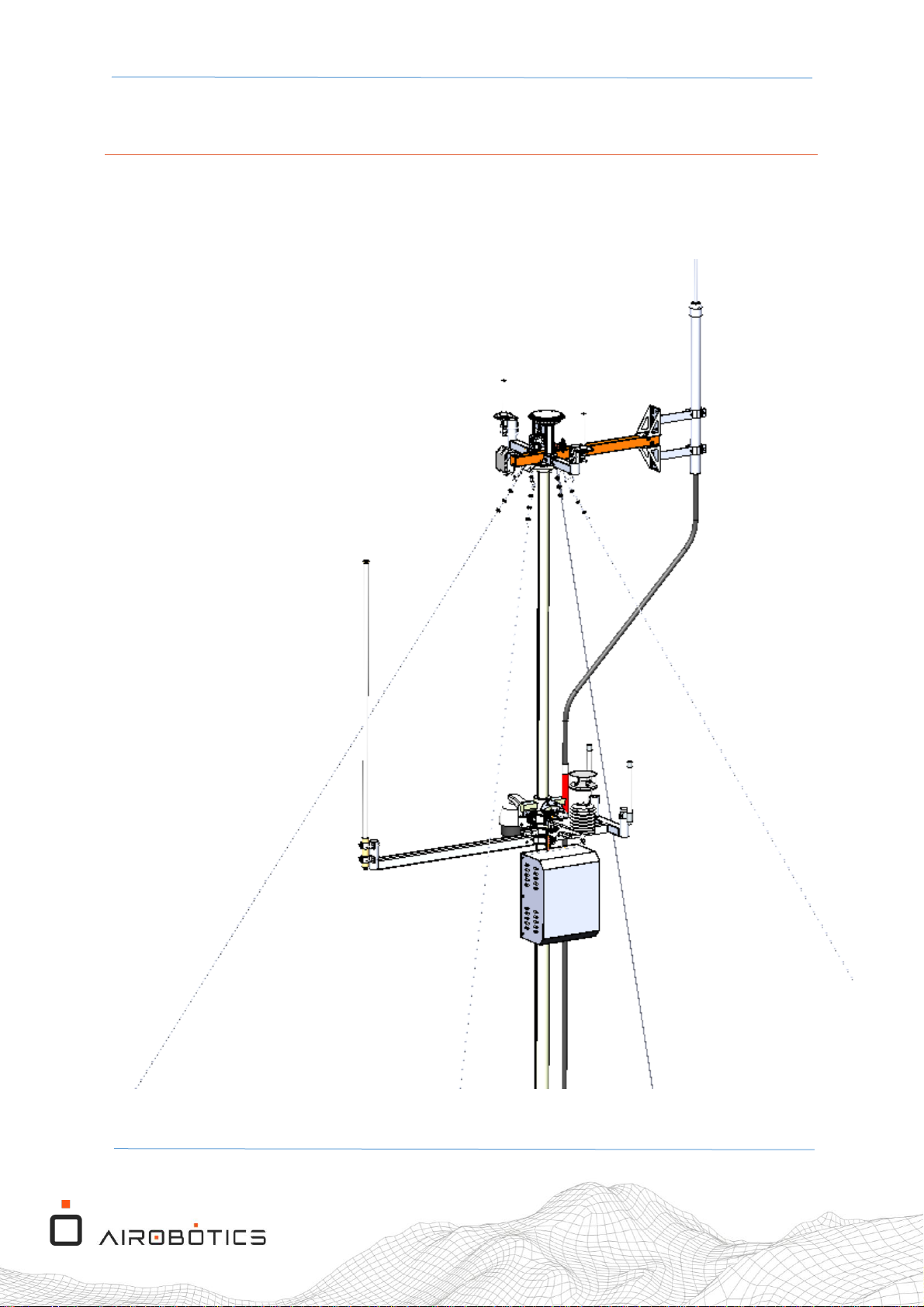
The FTS Mast Unit box is assembled on the upper mast, as illustrated in Figure 1.
Figure 1 The FTS Mast Unit box, mounted on the upper mast
Page 9
OPT1-M-104 Rev.01 Optimus-1 EX - FTS Mast Assembly Procedure
Page 9 of 33
3.2 FTS Mast Unit Parts List
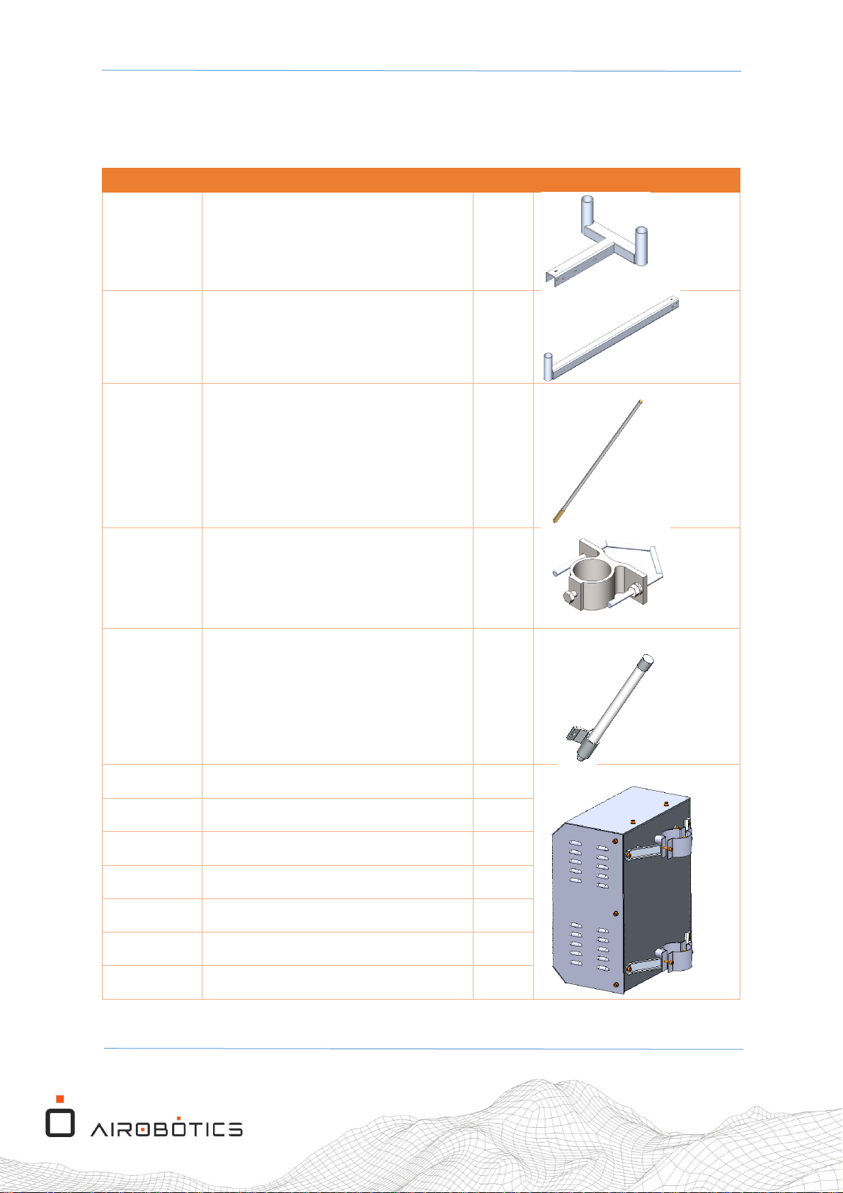
The FTS Mast Unit requires the following items for assembly on the mast (see Table 1).
PLM ID
Description
QTY
Image
MM05114
FTS Cellular Antennas Bracket
1
MM05112
FTS Main ANT Bracket
1
100108
Laird #FG9026
1
100109
Extruded Aluminum Mounting Bracket
2
100112
TAOGLAS #OMB.6912.03F21
2
MO05199
FTS Mast unit assembly
1
MO05346
FTS Mast Plate Holder
4
100107
Hold hanging with rubber
2 DIN 912 M6x40 zinc (screw)
4 DIN 912 M6x16 zinc (screw)
4 DIN 125 M6 st.st (washer)
4 DIN 985 M6 st.st (Nylock nut)
4
Table 1 Parts list for assembling the FTS Mast Unit box on the mast
Page 10
OPT1-M-104 Rev.01 Optimus-1 EX - FTS Mast Assembly Procedure
Page 10 of 33
3.3 Preparing the Antennas for Assembly
3.3.1 Preparing the Main Antenna for Assembly
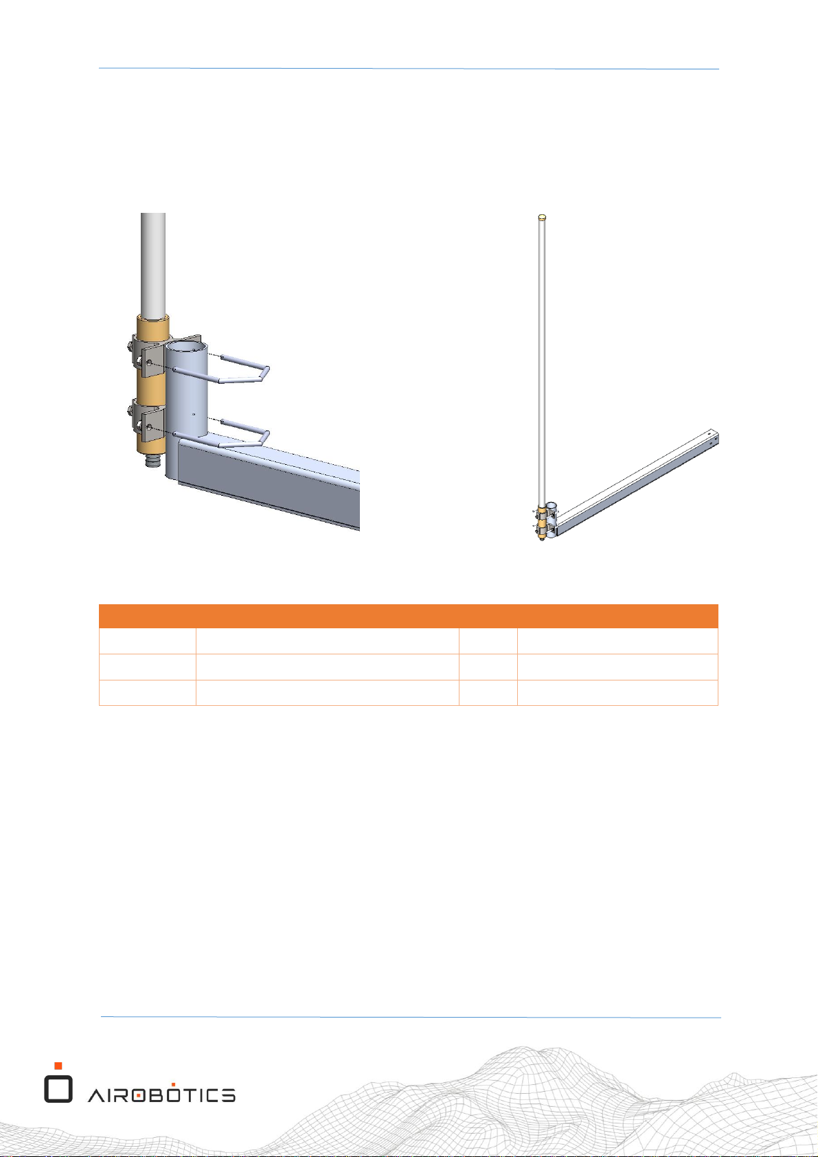
To prepare the antennas for assembly on the mast, assemble them to the antenna bracket,
as illustrated in Figure 2.
Figure 2 FTS Main Antenna bracket mounting
PLM ID
Description
QTY
Image
MM05112
FTS Main ANT Bracket
1
100108
Laird #FG9026Omnidirectional Antenna
1
100109
Extruded Aluminum Mounting Bracket
2
Table 2 Parts list for assembling the FTS main antenna on the bracket
Page 11
OPT1-M-104 Rev.01 Optimus-1 EX - FTS Mast Assembly Procedure
Page 11 of 33
3.3.2 Preparing the Taoglass Antennas for Assembly
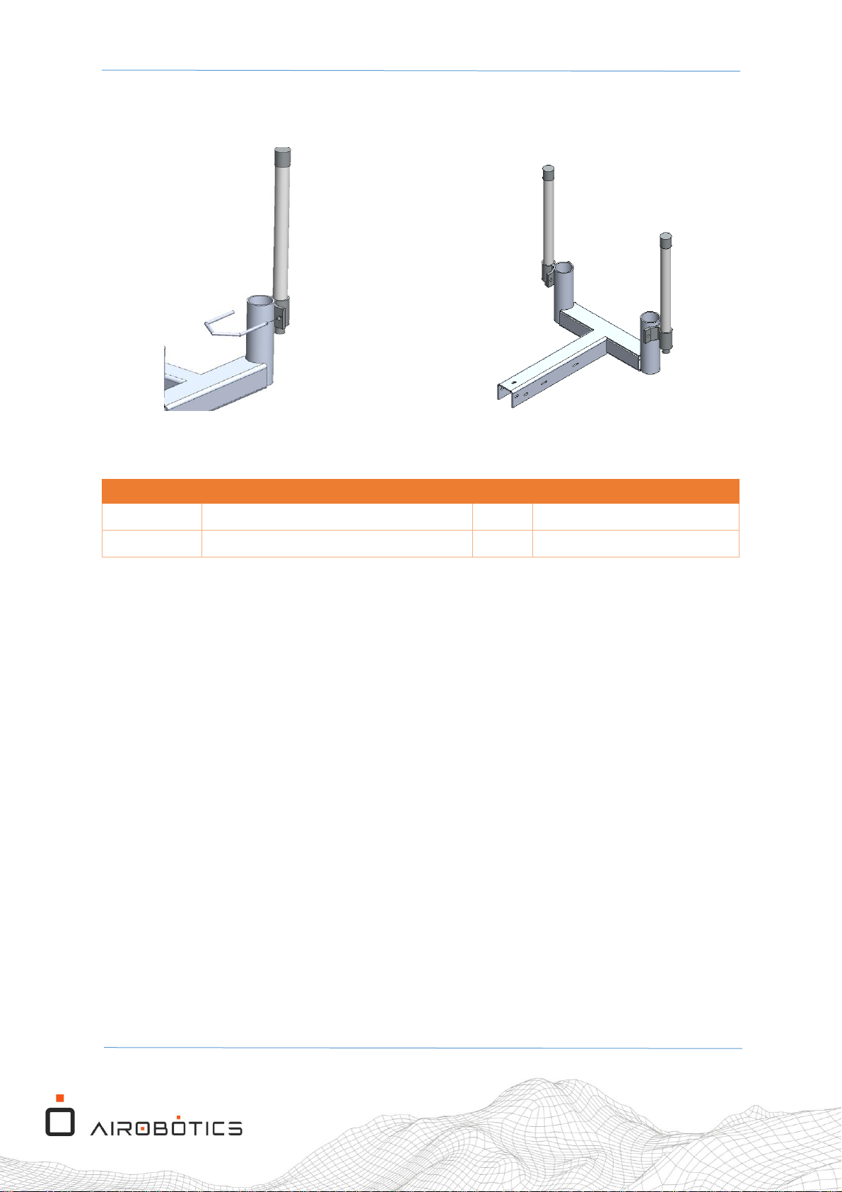
Figure 3 Taoglass RF antennas bracket mounting
PLM ID
Description
QTY
Image
100112
TAOGLAS #OMB.6912.03F21
2
MM05114
FTS Cellular Antennas Bracket
1
Table 3 Parts list for assembling the Taoglass antennas on the bracket
Page 12
OPT1-M-104 Rev.01 Optimus-1 EX - FTS Mast Assembly Procedure
Page 12 of 33
3.4 Mounting the Antennas on the Mast
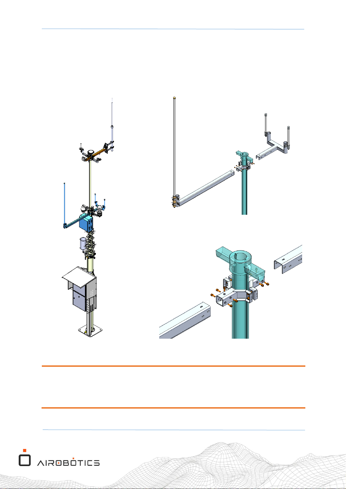
To mount the antennas on the upper mast, do the following:
1. Connect the Main antenna bracket to the V-bracket that’s located below the
camera/whether station V-bracket (see Figure 4).
Figure 4 Connecting the V-bracket sub-assemblies to the mast
NOTE:
Before proceeding to the next stage of the FTS assembly procedure, raise the second section
of the mast by a height of 80 cm (just below the point where it reaches its locking position).
Page 13
OPT1-M-104 Rev.01 Optimus-1 EX - FTS Mast Assembly Procedure
Page 13 of 33
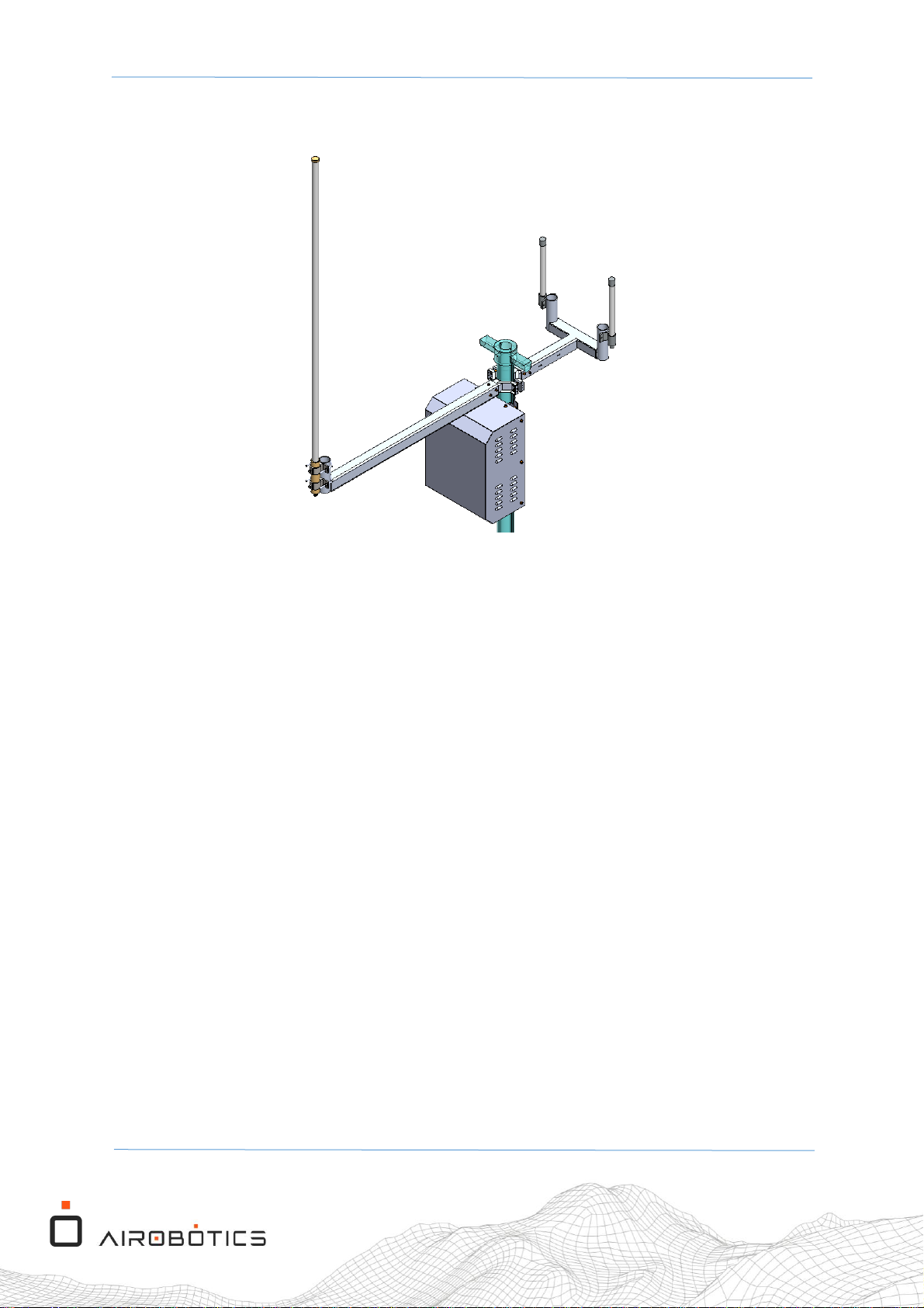
3.5 Mounting the FTS Unit Box on the Mast
Figure 5 The location of the FTS Mast Unit cabinet on the mast
Page 14
OPT1-M-104 Rev.01 Optimus-1 EX - FTS Mast Assembly Procedure
Page 14 of 33
To mount the FTS Mast Unit Box on the mast, do the following:
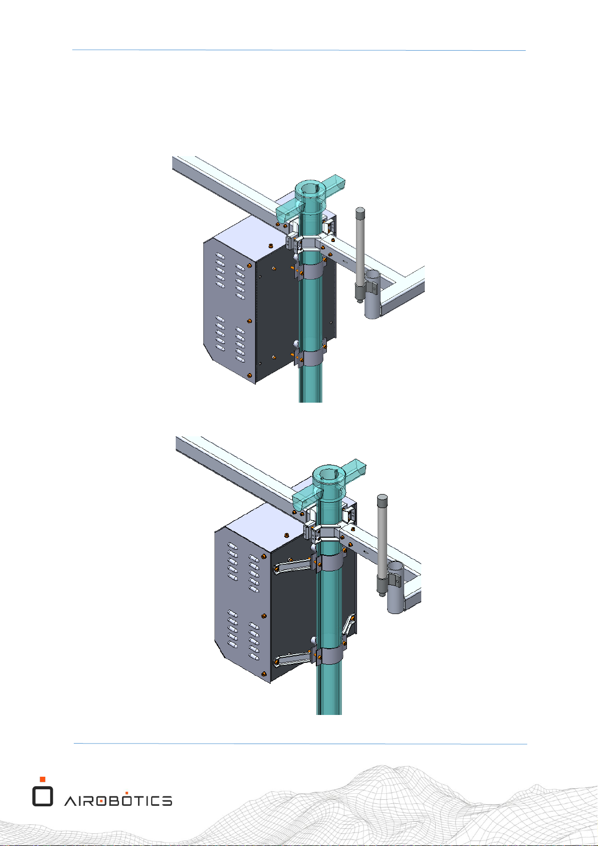
1. Attach the FTS cabinet to the mast with hold hanging (metal pole clamp) brackets, using
the screws that were prepared in advance (see Table 1 and Figure 6).
2. Attach the Plate Holders to the cabinet walls and to the clamps using the screws,
washers and Nylock nuts that were prepared in advance (see Table 1 and Figure 7).
Figure 6 Attach the hold hanging (metal pole clamp) brackets to the mast
Figure 7 Attach the plate holders to the brackets and cabinet back
Page 15
OPT1-M-104 Rev.01 Optimus-1 EX - FTS Mast Assembly Procedure
Page 15 of 33
4 FTS Mast Unit Electrical Assembly
4.1 SIM Card Installation
To install the SIM card into the FTS mast unit box, do the following:
1. Make sure that the FTS unit isn’t connected to any power source, neither AC (via POE
port) or Battery power.
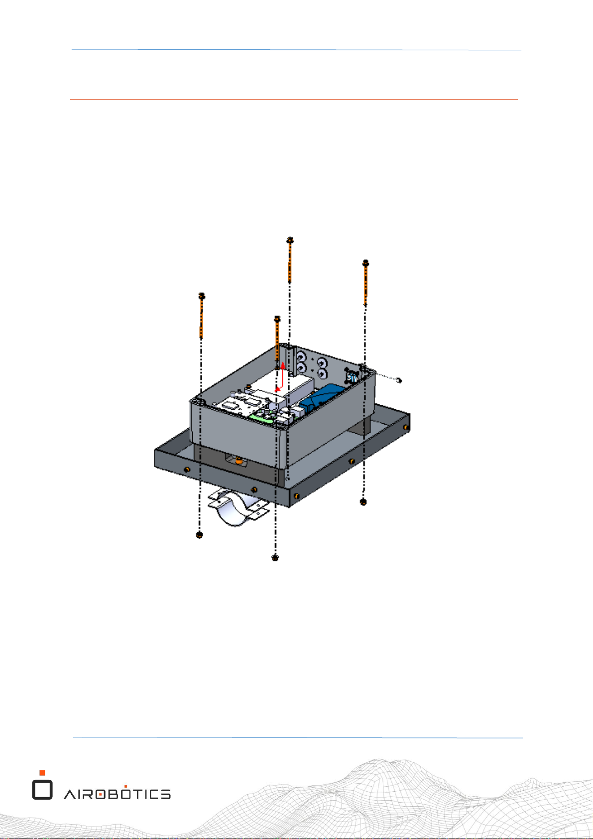
2. Unscrew the 4 screws from the lid of the FTS box and open the FTS cover (see Figure 8).
Figure 8 Open the lid of the FTS mast unit box
Page 16
OPT1-M-104 Rev.01 Optimus-1 EX - FTS Mast Assembly Procedure
Page 16 of 33
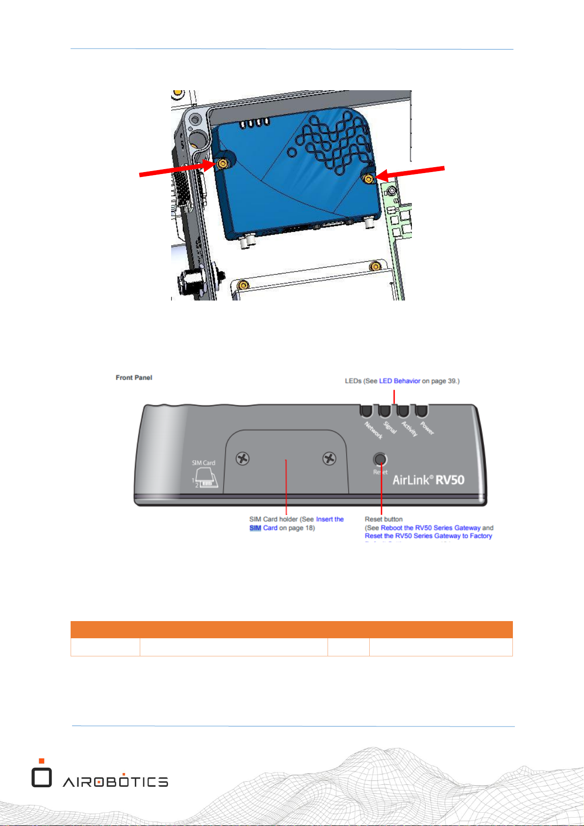
3. Unscrew the two screws that anchor the RV50 cellular modem (see Figure 9).
Figure 9 Open the lid of the RV50 cellular modem box
4. Lift the RV50 modem, and rotate it so that the SIM card holder opening is accessible
(see Figure 10)
Figure 10 The SIM Card holder lid
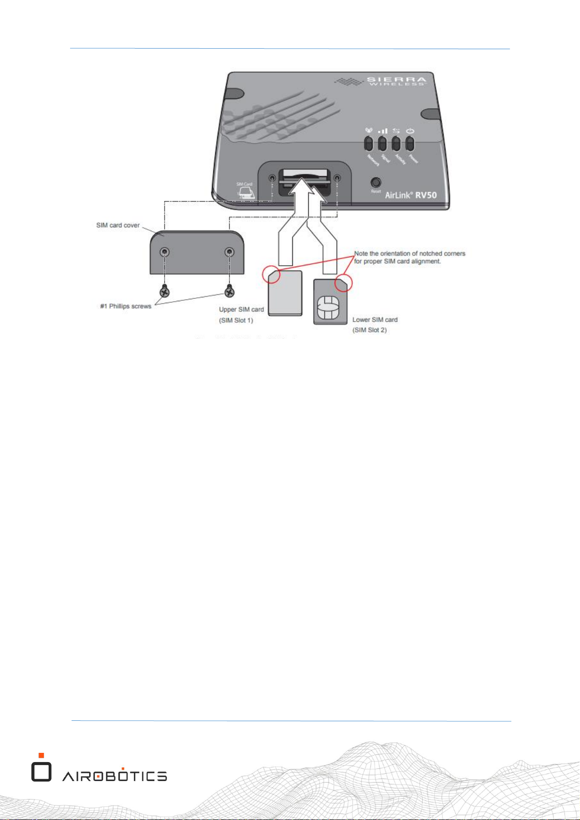
5. Open the 2 Philips screws of the lid for the SIM Card holder.
6. Insert either 1 or 2 SIM cards. Orientation should be as illustrated in Figure 11.
PLM ID
Description
QTY
Image
100269
4G SIM Card
1 or 2
Table 4 Parts list for the SIM card/s
Page 17
OPT1-M-104 Rev.01 Optimus-1 EX - FTS Mast Assembly Procedure
Page 17 of 33
Figure 11 The orientation of the SIM cards in the SIM Card holder
7. Close the cover of the SIM card holder and screw its screws back on.
8. Screw on the RV50 modem back into the panel of the FTS mast unit box, and then
close the cover of the box, with the screws.
Page 18
OPT1-M-104 Rev.01 Optimus-1 EX - FTS Mast Assembly Procedure
Page 18 of 33
4.2 Battery Installation
To install the battery into the FTS mast unit box, do the following:
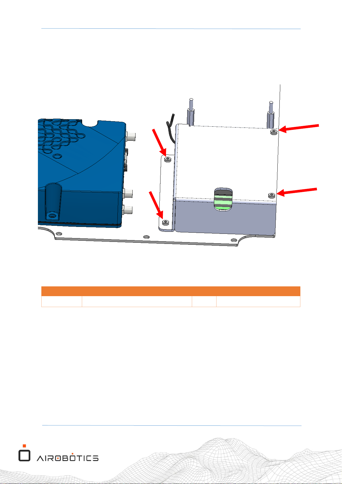
1. Unscrew the 4 screws of the battery holder (see Figure 12).
Figure 12 The battery holder and its 4 screws
PLM ID
Description
QTY
Image
E005124
LiFePo4 2S2P FTS battery
1
Table 5 Parts list for the SIM card/s
2. Place the battery in its socket (see Figure 13), and in the correct orientation.
3. Close the MO05202 battery cover with the 4 screws (M4X12 DIN912).
Page 19
OPT1-M-104 Rev.01 Optimus-1 EX - FTS Mast Assembly Procedure
Page 19 of 33
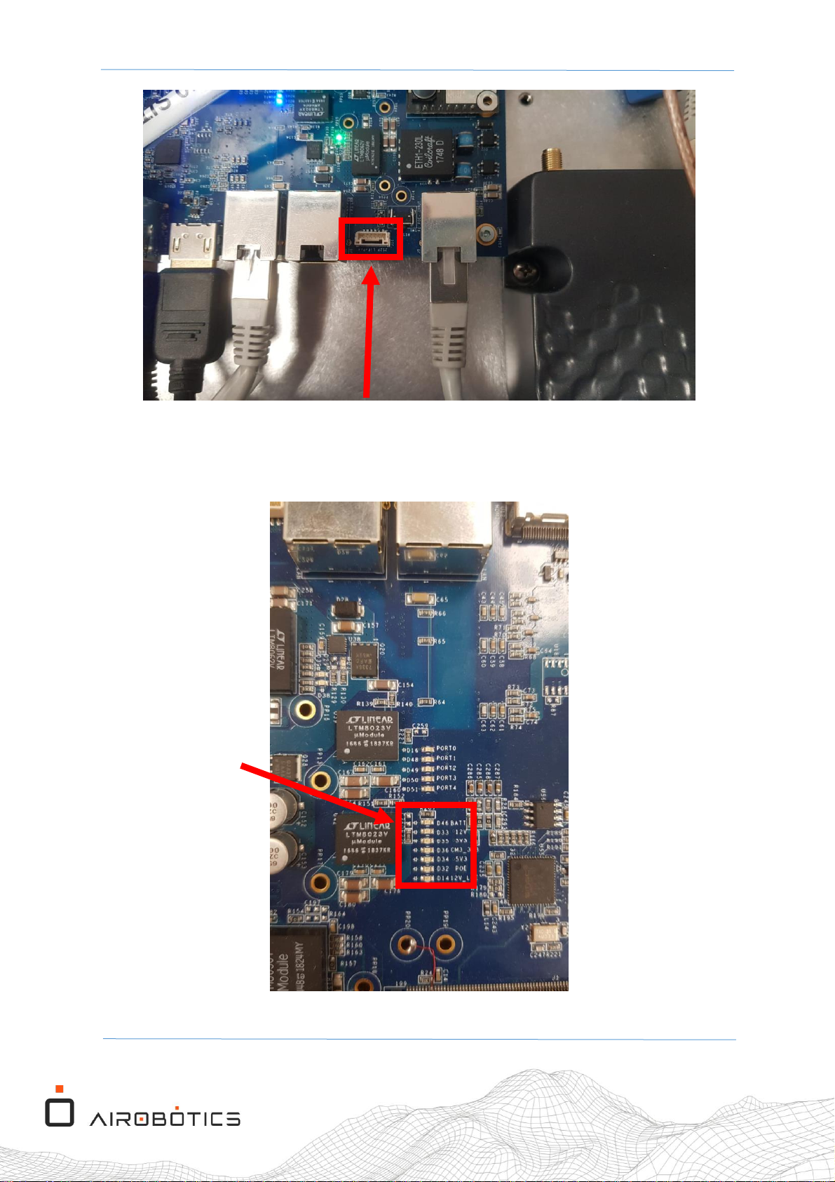
Figure 13 The battery socket
4. Connect the battery lead connector into the FTS_V1EX_MAIN_PCB (EO05016) connector
J16 (see Figure 13).
Figure 14 The Power LEDs
2S2P LiFePo4 Battery
Power LEDs
Page 20

OPT1-M-104 Rev.01 Optimus-1 EX - FTS Mast Assembly Procedure
Page 20 of 33
5. If the battery was connected correctly, then all the power LEDs (except D32 "POE" LED)
should be turned on (see Figure 14).
6. Close the FTS unit, make sure to have the cover 4 screw firmly tightened.
Page 21
OPT1-M-104 Rev.01 Optimus-1 EX - FTS Mast Assembly Procedure
Page 21 of 33
4.3 FTS Electrical Assembly
4.3.1 Connecting the Antenna Electrical Cables
PLM ID
Description
QTY
Image
100266
CBL Assy N-TYPE PLUG LMR 400 6'
2
MM05114
CBL FTS 15m POE + Cable
1
Table 6 Parts list for antenna cables
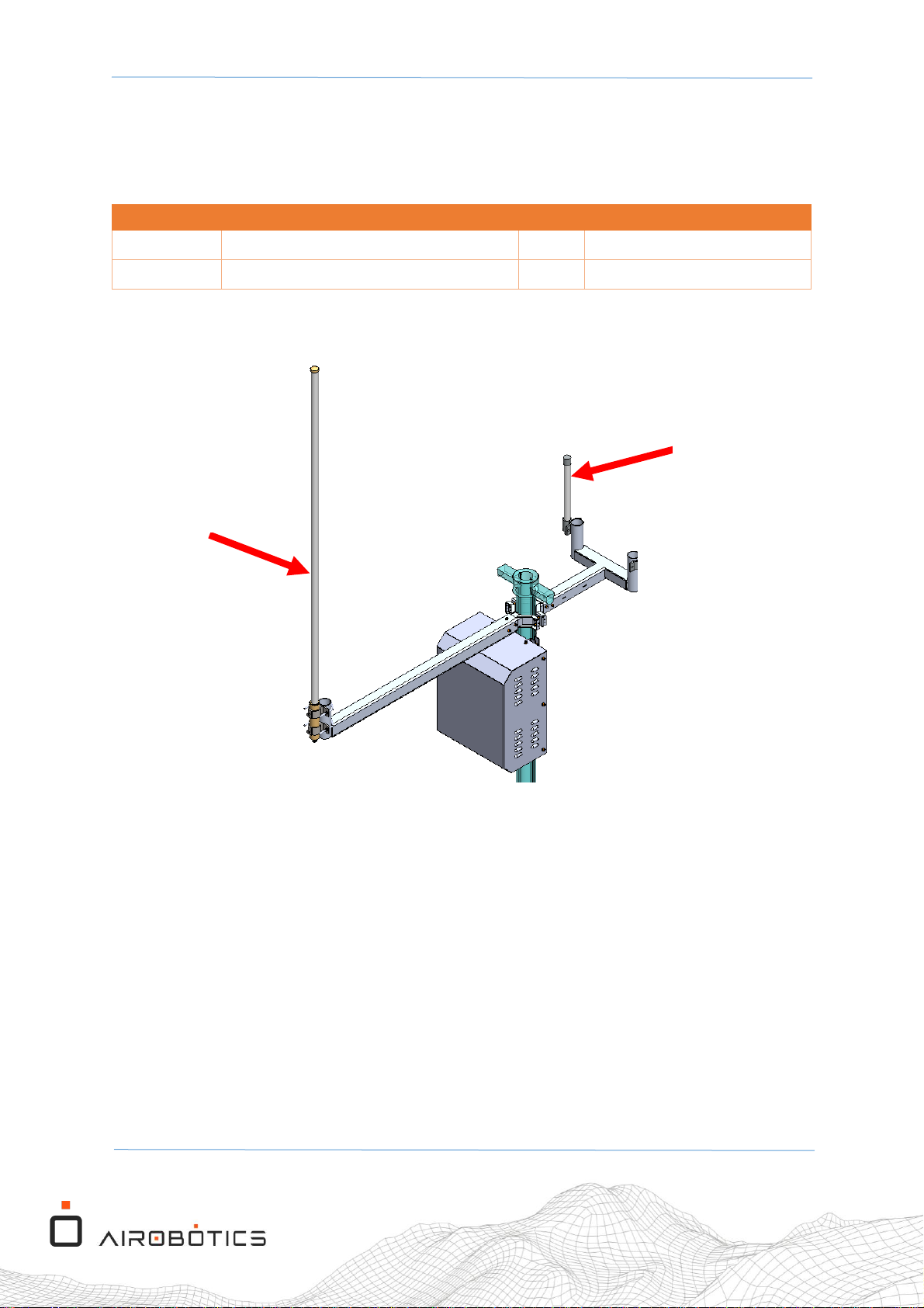
Figure 15 Antenna types
To connect the antennas to the FTS mast unit box, do the following:
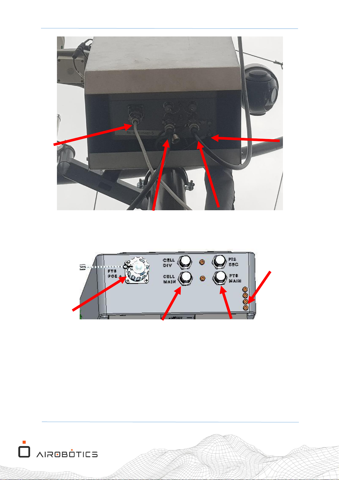
1. Connect the cellular antenna cable LMR400 (PN: 100266) from the cellular antenna
(001238) to the "CELL MAIN" N TYPE connector (see Figure 16 and Figure 17).
2. Connect the LoRa antenna cable LMR400 (PN: 100266) from the LoRa antenna (001181)
into "FTS MAIN" N TYPE connector (see Figure 16 and Figure 17).
3. Add the CAT7 15m (EO05277) cable into the mast cable protection sleeve.
4. Connect the CAT7 15m (EO05277) from the mast panel connection (2J10) to the FTS
box POE + connector (see Figure 16 and Figure 17).
5. Connect the FTS ground cable into the mask ground bar.
LoRa
Antenna
Cellular
Antenna
Page 22
OPT1-M-104 Rev.01 Optimus-1 EX - FTS Mast Assembly Procedure
Page 22 of 33
Figure 16 Cable connections in the FTS mast unit back panel
Figure 17 The FTS mast unit back panel
6. Connect the POE+ port from the FTS unit to the DC panel external connection marked as
port 2J10 using the EO05277 CAT7 15m cable (see Figure 16).
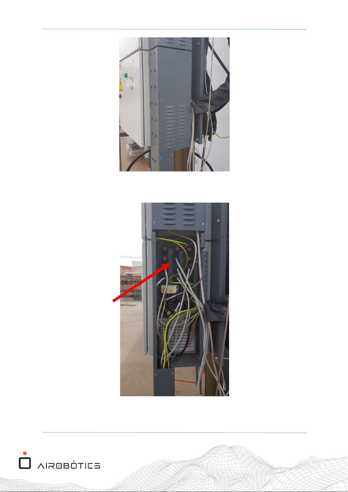
7. Open the mast output interfaces cover panel (unscrew the 5 Philips head screws).
Ground
From LoRa Antenna
POE +
From DC
Panel 2J10
From LoRa Antenna
Ground
POE +
From DC
Panel 2J10
Page 23
OPT1-M-104 Rev.01 Optimus-1 EX - FTS Mast Assembly Procedure
Page 23 of 33
Figure 18 The mast unit interfaces cover panel
8. Connect the CAT7 15m cable into the FTS port 2J10
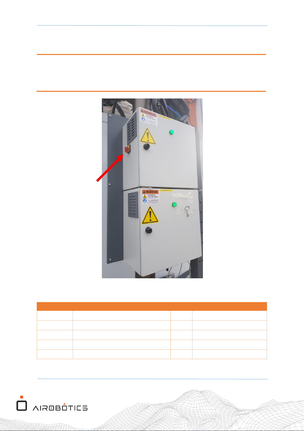
Figure 19 The mast unit interfaces panel
9. Close the mast output interfaces cover panel (using the 5 Philips-head screws).
2J10
Port
Page 24
OPT1-M-104 Rev.01 Optimus-1 EX - FTS Mast Assembly Procedure
Page 24 of 33
4.4 DC Electrical Panel Modifications
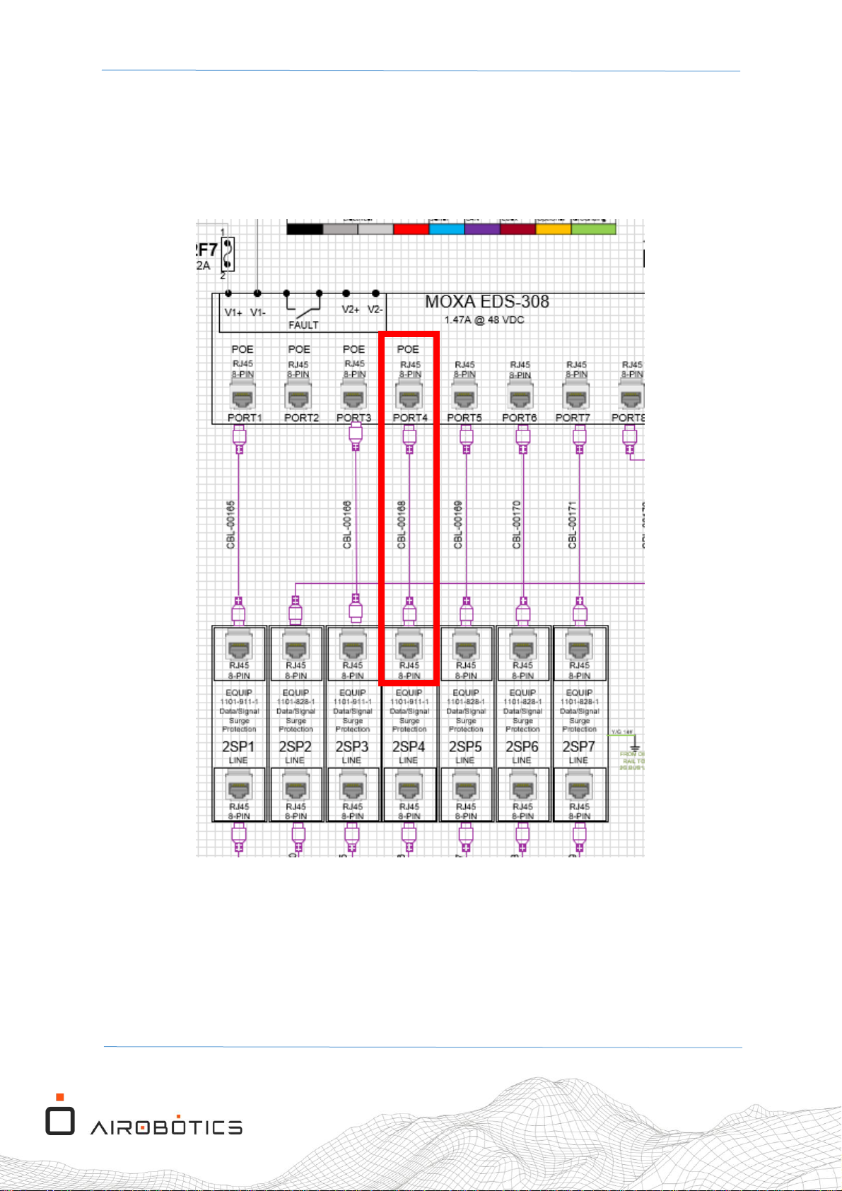
IMPORTANT NOTE:
Before performing any work on the DC/AC mast electrical panels, make sure to turn OFF
the Mast Unit’s main power switch, and the internal UPS switch (inside the AC cabinet)!!!
Figure 20 The Mast main power switch
PLM ID
Description
QTY
Image
001187
POE+ Injector
1
000140
LAN CAT6 Cable 0.3m
1
004150
Wire, 22AWG, 300V, Red, UL
1m
004151
Wire, 22AWG, 300V, Black, UL
1m
000217
Insulated Ferrule
6
Table 7 Parts list for DC electrical panel modifications
Main Power
Switch
Page 25
OPT1-M-104 Rev.01 Optimus-1 EX - FTS Mast Assembly Procedure
Page 25 of 33
4.4.1 Disconnecting Wires and Cables
Perform the following wiring modifications to the DC electrical panel:
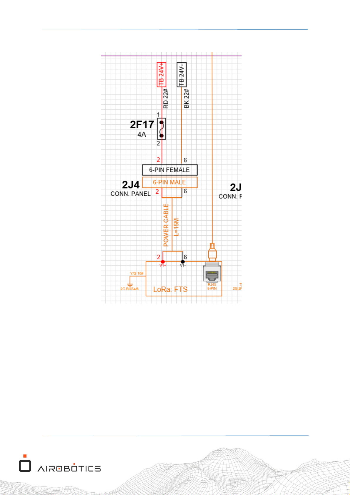
1. Disconnect the LAN cable that connects Port 4 from the MOXA to the 2SP4 surge
protection module (see Figure 21).
Figure 21 The LAN cable from MOXA Port 4 (POE) to the 2SP4 module
Page 26
OPT1-M-104 Rev.01 Optimus-1 EX - FTS Mast Assembly Procedure
Page 26 of 33
2. Disconnect the wire that connects the 2J4 connector to the 2F17 fuse (see Figure 22).
Figure 22 The wire connecting the 2J4 connector to the 2F17 fuse
Page 27
OPT1-M-104 Rev.01 Optimus-1 EX - FTS Mast Assembly Procedure
Page 27 of 33
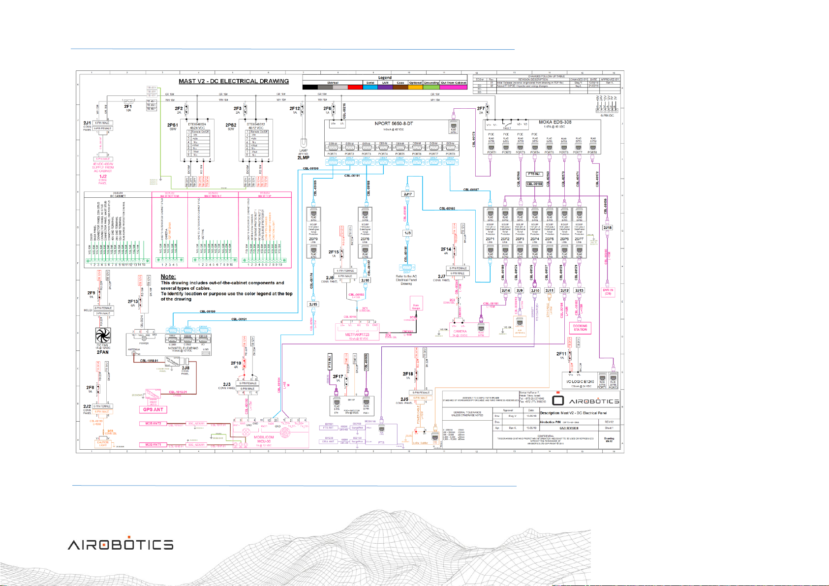
Figure 23 Electrical diagram of the Mast (V1 EX) DC electrical panel
Page 28
OPT1-M-104 Rev.01 Optimus-1 EX - FTS Mast Assembly Procedure
Page 28 of 33
NOTE:
Figure 23 illustrates an electrical diagram of the Mast’s DC electrical panel, after the
modifications have been completed.
4.4.2 Installing POE Injector
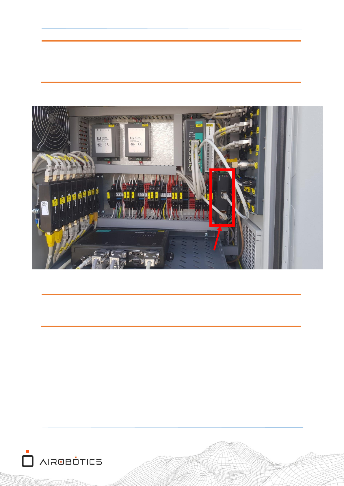
Figure 24 The location of the POE-162 Injector after installation
NOTE:
If the designated location of the POE is not clear, contact the Mechanical Engineering team.
POE-162
Injector
Page 29
OPT1-M-104 Rev.01 Optimus-1 EX - FTS Mast Assembly Procedure
Page 29 of 33
To install the POE-162 Injector into the DC electrical circuits box, do the following:
1. Mount the POE on the metal DIN mounting rail (see Figure 25).
Figure 25 Mount the POE-162 Injector on the DIN mounting rail
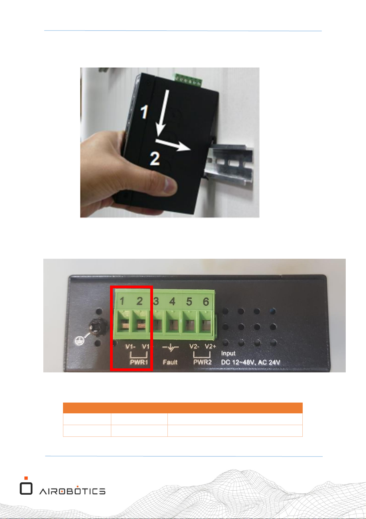
2. Connect the power input wires into the POE+ injector connector panel as shown in
Figure 26 and as specified in Table 8.
Figure 26 The POE+ Injector power input wiring panel terminators
3. Connect the power input wires into the POE+ connector panel as follows:
Pin Number
Description
Comments
1
48V+
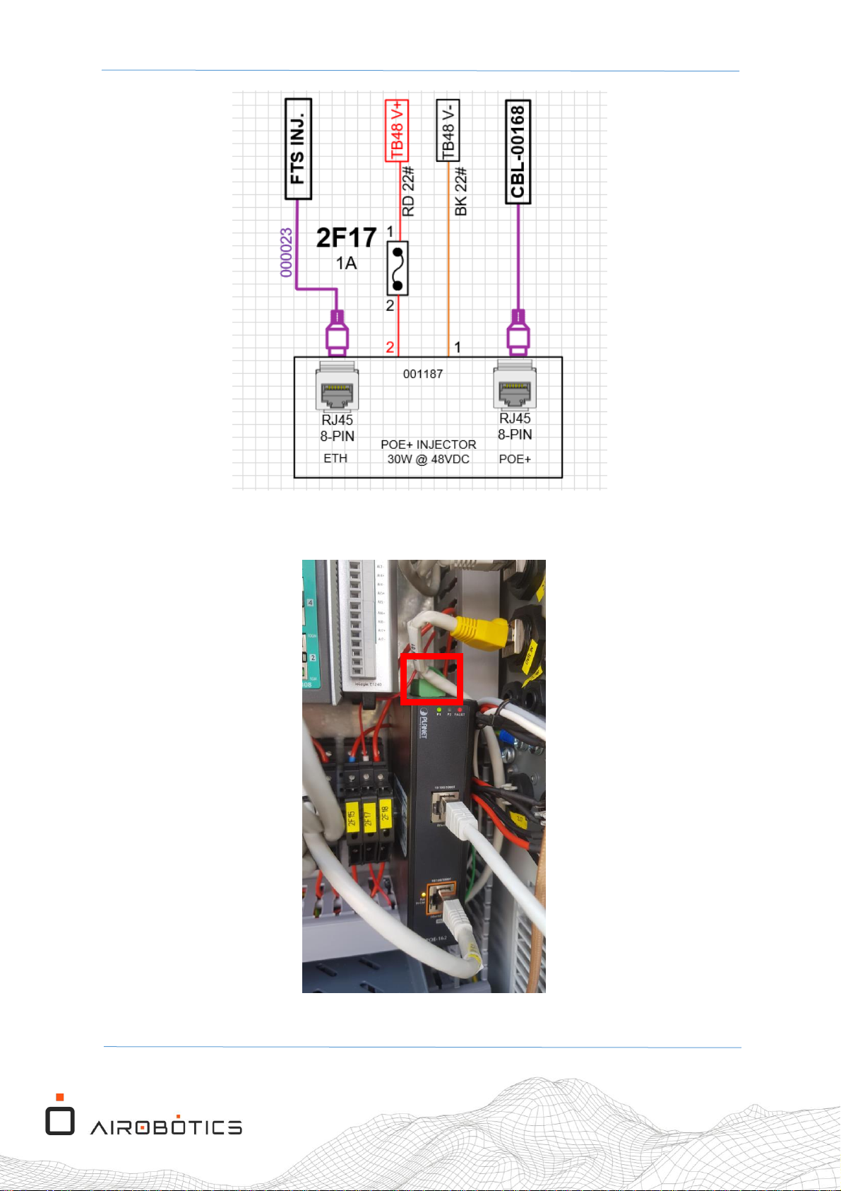
Connect via 1A fuse 2F17 (see Figure 27)
2
48V-
GND
Table 8 POE+ Injector power input wiring panel terminators
Page 30
OPT1-M-104 Rev.01 Optimus-1 EX - FTS Mast Assembly Procedure
Page 30 of 33
Figure 27 Connect the 48V+ wire via the 1A fuse 2F17
4. Connect the injector power connection into the POE+ unit (see Figure 28).
Figure 28 Connect the injector power into the POE+ unit
Page 31
OPT1-M-104 Rev.01 Optimus-1 EX - FTS Mast Assembly Procedure
Page 31 of 33
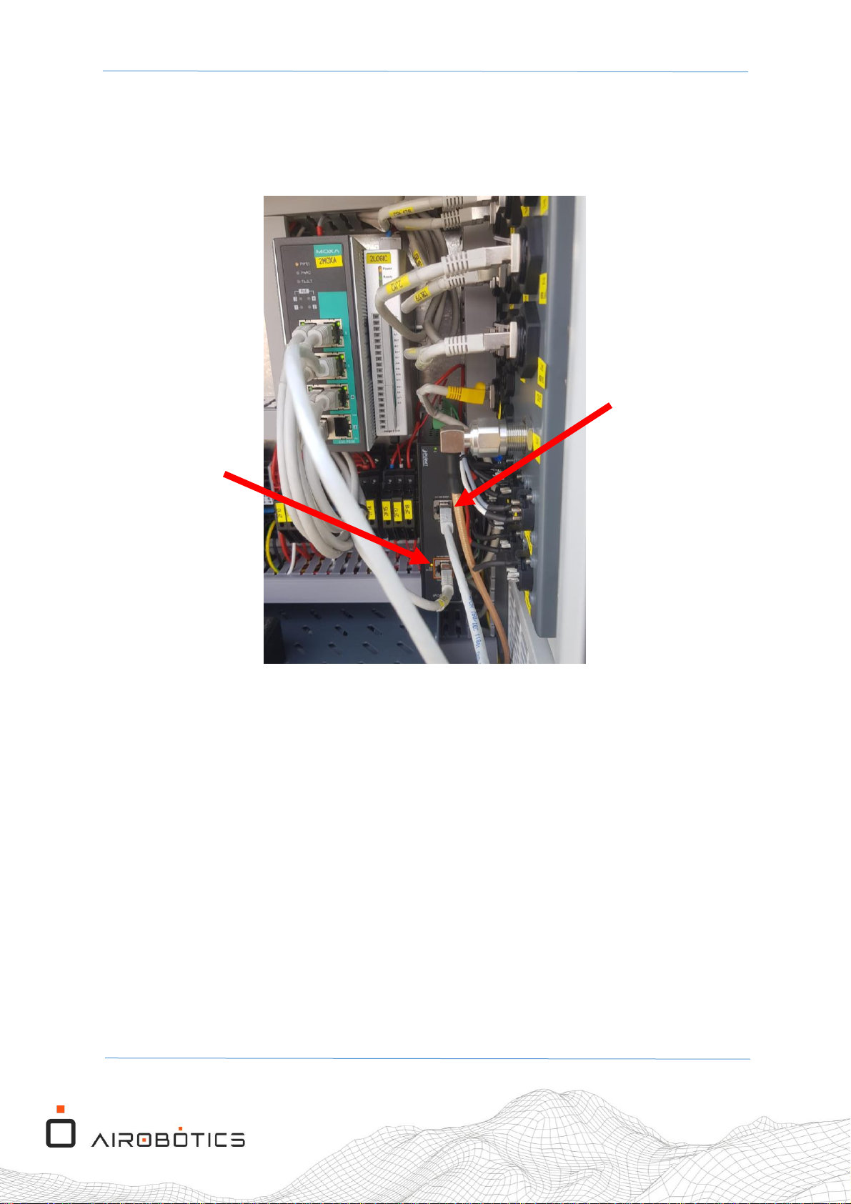
5. Connect the POE+ Ethernet + DC port (POE port) into CBL-00168 cable (connected into
Surge protector "2SP4") (see Figure 29).
6. Connect the POE+ Ethernet port (10/100 port) into the MOXA at port 4 with short CAT6A
cable (0.5m) (see Figure 29).
Figure 29 Connect cables into the RJ45 interfaces
Connect into
"2SP4" via
CBL-00168
Connect to
MOXA "Port 4"
Page 32
OPT1-M-104 Rev.01 Optimus-1 EX - FTS Mast Assembly Procedure
Page 32 of 33
7. Turn ON the Mast main power switch (see Figure 20).
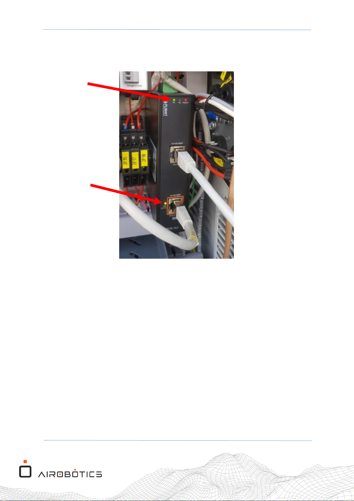
8. Make sure that the POE injector Green LED "P1" is turned on (see Figure 30).
9. Make sure that the POE injector Orange LED "POE IN-USE" is turned on (see Figure 30).
Figure 30 The P1 and POE In-Use indicator LEDs
10. The FTS Mast Unit has been successfully installed.
P1
POE IN-USE
Page 33

OPT1-M-104 Rev.01 Optimus-1 EX - FTS Mast Assembly Procedure
Page 33 of 33
5 FCC Compliance Statement
This device has been tested and found to comply with the limits for a Class B digital device, pursuant to Part 15 of the FCC Rules.
These limits are designed to provide reasonable protection against harmful interference in residential installations. This
equipment generates uses and can radiate radio frequency energy and, if not installed and used in accordance with the
instructions, may cause harmful interference to radio and television reception.
However, there is no guarantee that interference will not occur in a particular installation. If this device does cause such
interference, which can be verified by turning the device off and on, the user is encouraged to eliminate the interference by one
or more of the following measures:
– Re-orient or re-locate the receiving antenna.
– Increase the distance between the device and the receiver.
– Connect the device to an outlet on a circuit different from the one that supplies power to the receiver.
– Consult the dealer or an experienced radio/TV technician.
WARNING! Changes or modifications to this unit not expressly approved by the party responsible for compliance could void
the user’s authority to operate the equipment.
WARNING! A distance of at least 20cm should be maintained between the antennas and all persons during the operation of
the of this device
 Loading...