

Page 1
Troubleshooting Guide
Problem Reason Solution
Unit does not turn on. 1. Power Cord
2. AHPCO™ Cell
3. Indicator Light Not
Working
1. Check to make sure
power cord is plugged
in or properly connected to HVAC unit.
2. Check to make
sure UV lamp within
AHPCO™ Cell in
plugged in completely.
3. Make sure exposed
end of black ber optic
cord is exposed to the
UV light.
Dual Induct
(120v)
Owner’s
Manual
3401 Airway Blvd
Amarillo, TX 79118
Toll-Free: 1-800-936-1764 Fax: 1-806-373-7799
www.AirOasis.com
Copyright© 2006 Air Oasis All Rights Reserved
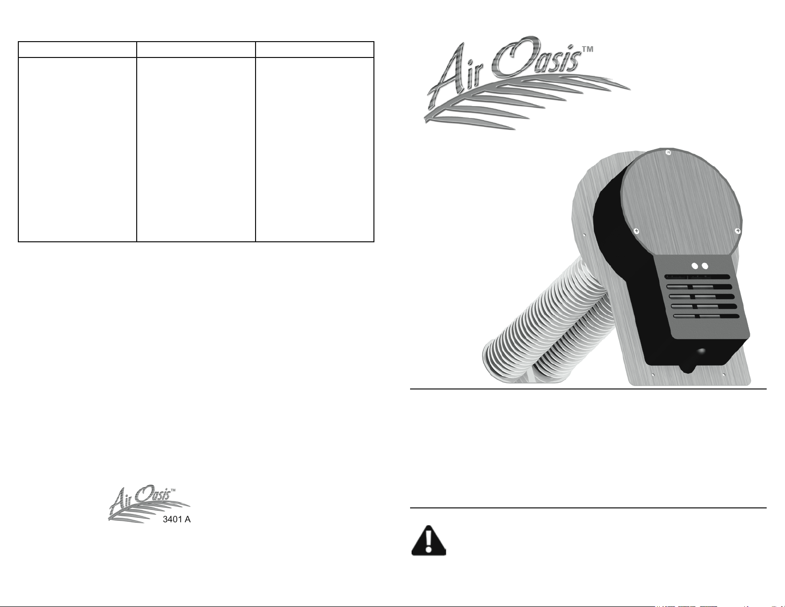
This Manual Includes:
• Warranty
• Safety Warnings
• Installation Instructions
• Operating Instructions
• Replacement Directions
• Troubleshooting Tips
Before operating this unit or replacing the AHPCO™
Cell carefully read the contents of this manual.
Page 2
Important Safety Instructions
Step 3
When operating electrical appliances, basic precautions should always be followed.
WARNING To reduce the risk of re, electric shock or injury:
• Do not use outdoors or on wet surfaces.
• Use only as described in this manual.
• Do not use with damaged cord or plug. If appliance is not working as it should,
has been dropped, damaged, left outdoors, or dropped into water, call customer
service at 1-800-936-1764.
• Do not unplug by pulling on cord. To unplug, grasp the plug, not the cord.
• Do not handle plug or appliance with wet hands.
• Do not put any object into openings.
• Turn off all controls before unplugging.
CAUTION
AHPCO™ Cell contains Hg (Mercury) and should be disposed of according to
disposal laws. Find disposal centers at www.earth911.org.
If the UV lamp is broken do not touch the cell or glass with your hands.
UV lamp may be hot and could cause serious burns if not handled properly. Please
wait until the AHPCO Cell has cooled to room temperature to remove from unit.
WARNING: UV Light Hazard. Harmful to skin and eyes. Can cause
temporary or permanent loss of vision. Never look at the lamp while
illuminated. To prevent exposure to ultraviolet light, be sure the power is disconnected before servicing.
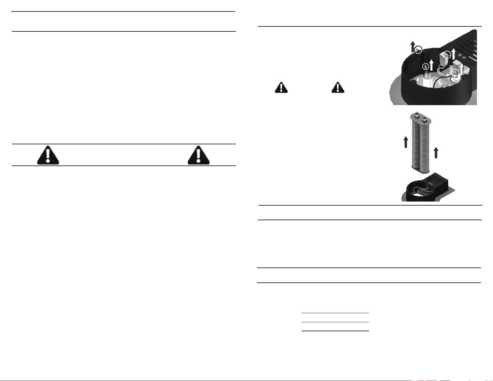
Remove four (4) wing-nuts securing the AHPCO Cell in place. Then
slide the AHPCO Cell up and out of
the unit.
CAUTION
UV lamp may be hot and could
cause serious burns if not handled
properly. Please wait until AHPCO
Cell has cooled to room temperature to remove from unit.
AHPCO™ Cell contains Hg (Mercury) and should be disposed of
according to disposal laws. Find
disposal centers at www.earth911.
org.
Step 4
Reverse steps 1-3 to set new AHPCO Cell in place. Be sure to place the
exposed tip of the ber optic cord between the rst rings of the new AHPCO
Cell and in close proximity to the UV lamp. This will ensure the indicator
light functions properly.
WARNING: RISK OF ELECTRICAL SHOCK. CAN CAUSE INJURY OR DEATH: UNPLUG OR DISCONNECT UNIT FROM POWER
SUPPLY BEFORE SERVICING.
Disclaimer – The health aspects associated with the use of this
product and its ability to aid in disinfection of environment air have
not been investigated by UL, located on front panel of xture and in
the instruction manual.
1 6
Replacement Date Reminder
The AHPCO™ Cell should be replaced every three years.
3 Years Date:
6 Years Date:
9 Years Date:
Hg lamp contains mercury. Manage in accord with disposal laws.
Find disposal centers at www.earth911.org.
Page 3
Dual Induct Installation Instructions
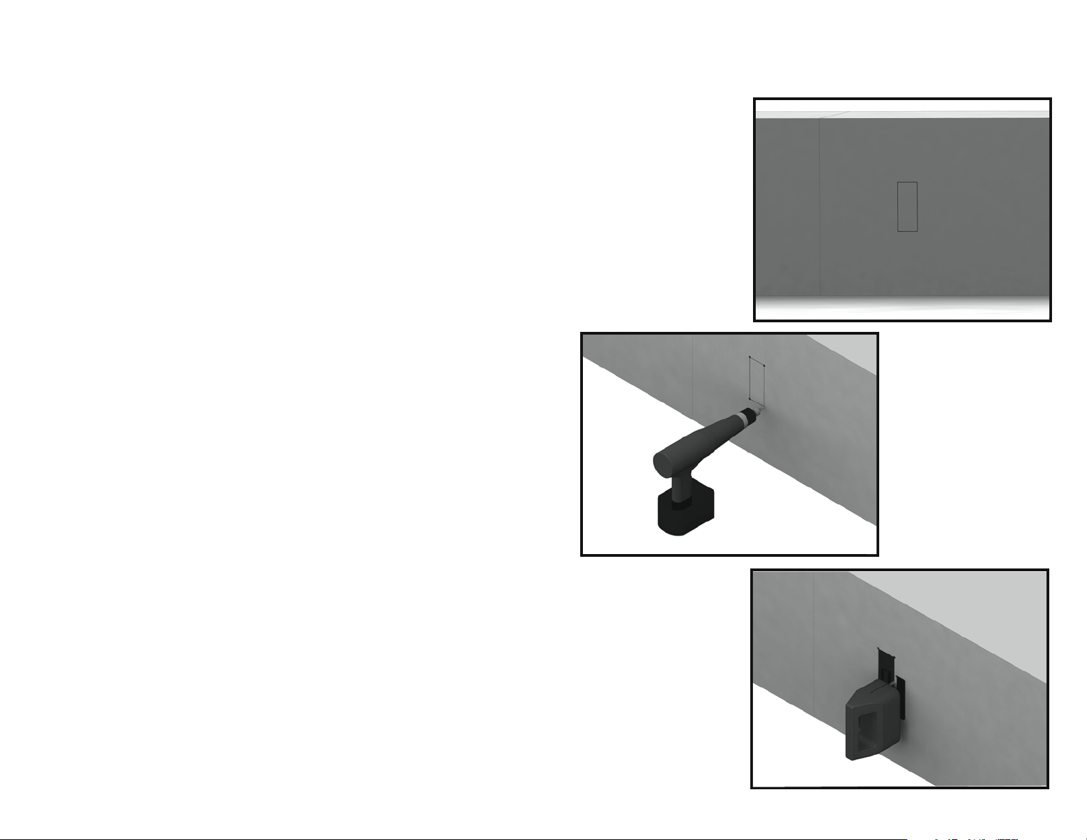
Step 1
Tear out the cutout template and trace
the rectangle onto the
ductwork.
Step 2
Drill holes at
each corner of the rectangle.
Step 3
Cut the rectangle out of the ductwork
with a jig saw or a pair
of metal cutting snips.
Page 4
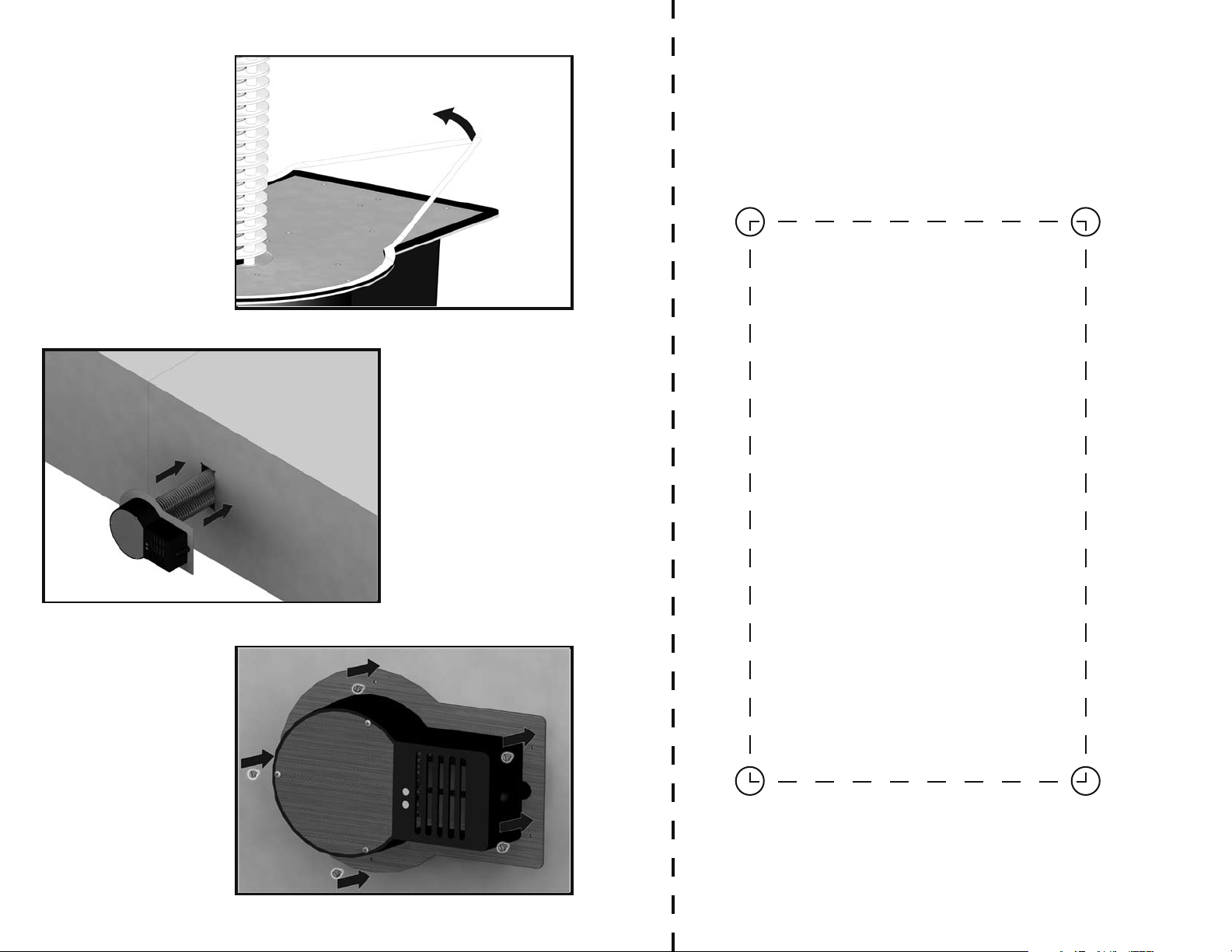
Step 4
Remove the wax
paper from the gasket.
Step 5
Insert unit into
pre-cut hole.
Tear this page o and cut the rectangle out. Then place
on the duct work in desired position and trace the rectangle. Drill holes as indicated and then use a jig saw or
metal cutting snips to cut out the rectangle.
Cut Out
Step 6
Drill the metal
tapping screws in to
hold unit in place.
Page 5
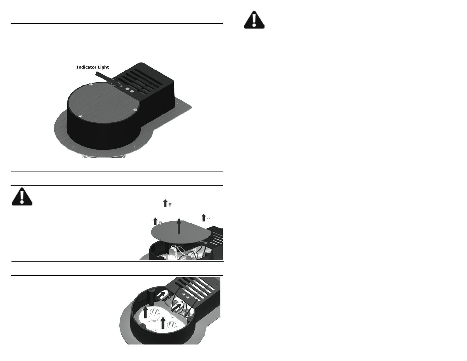
Step 4
Plug the power cord into an electrical outlet. You may optionally have an
electrician wire the air purier to your HVAC unit so that the air purier only
operates when your HVAC fan is running. Once the unit is plugged in the
indicator light should glow to indicate the AHPCO Cell is working properly.
Read all instructions carefully before operating
your air purier.
Table of Contents
Safety Instructions and Cautions 1
Table of Contents 2
Warranty 3
Maintenance and Customer Service 4
AHPCO™ Cell Replacement
Step 1
CAUTION: Before attempting to service the Air Oasis unit, be sure the
power is off and unplugged.
Remove three (3) screws at the top of
the aluminum face plate. Then slide
the face plate up and off.
Step 2
Unplug the four pin lamp connectors and ber optic cords from the
AHPCO Cell.
Placement and Operation 4
Cleaning 4
AHPCO™ Cell Replacement 5-6
Troubleshooting Guide 7
5
2
Page 6
Warranty Maintenance and Customer Service
Air Oasis gives you the following limited warranty for this product only if it was originally purchased for residential or commercial use but, not resale from Air Oasis or
an Air Oasis Authorized Retail Dealer.
Air Oasis will repair or replace, free of charge, to the original purchaser, any part
that is found to be defective in material or workmanship within three (3) years of
the date of purchase.
This limited warranty covers the replacement of a defective AHPCO Cell for a period of three years.
This limited warranty does not apply to any part subjected to accident, abuse, certain commercial uses, alteration, misuse, damage caused by act of God, the use
of voltages other than indicated on the label displayed on this product or service of
this product by anyone other than Air Oasis.
Air Oasis does not authorize any person or representative to assume or grant any
other warranty obligation with the sale of this product.
Air Oasis’ limited warranty is valid only if you retain proof of purchase from Air Oasis or an Air Oasis Authorized Retail Dealer for this product. If you purchase this
product from any other source, your purchase is “AS IS”, which means Air Oasis
grants you no warranty, and that you, not Air Oasis, assume the entire risk of the
quality and performance of this product, including the entire cost of any necessary
servicing or repairs of any defects.
If you require any additional information or have problems with your Air Oasis appliance, you may call Air Oasis customer service at:
1-800-936-1764
Please have your serial and model numbers, found on bottom of the unit, handy
when calling.
Save your sales receipt to show if your Air Oasis appliance should ever need any
warranty service.
Installation and Operation
It’s strongly recommended that only a licensed electrician
or HVAC installer properly install this unit.
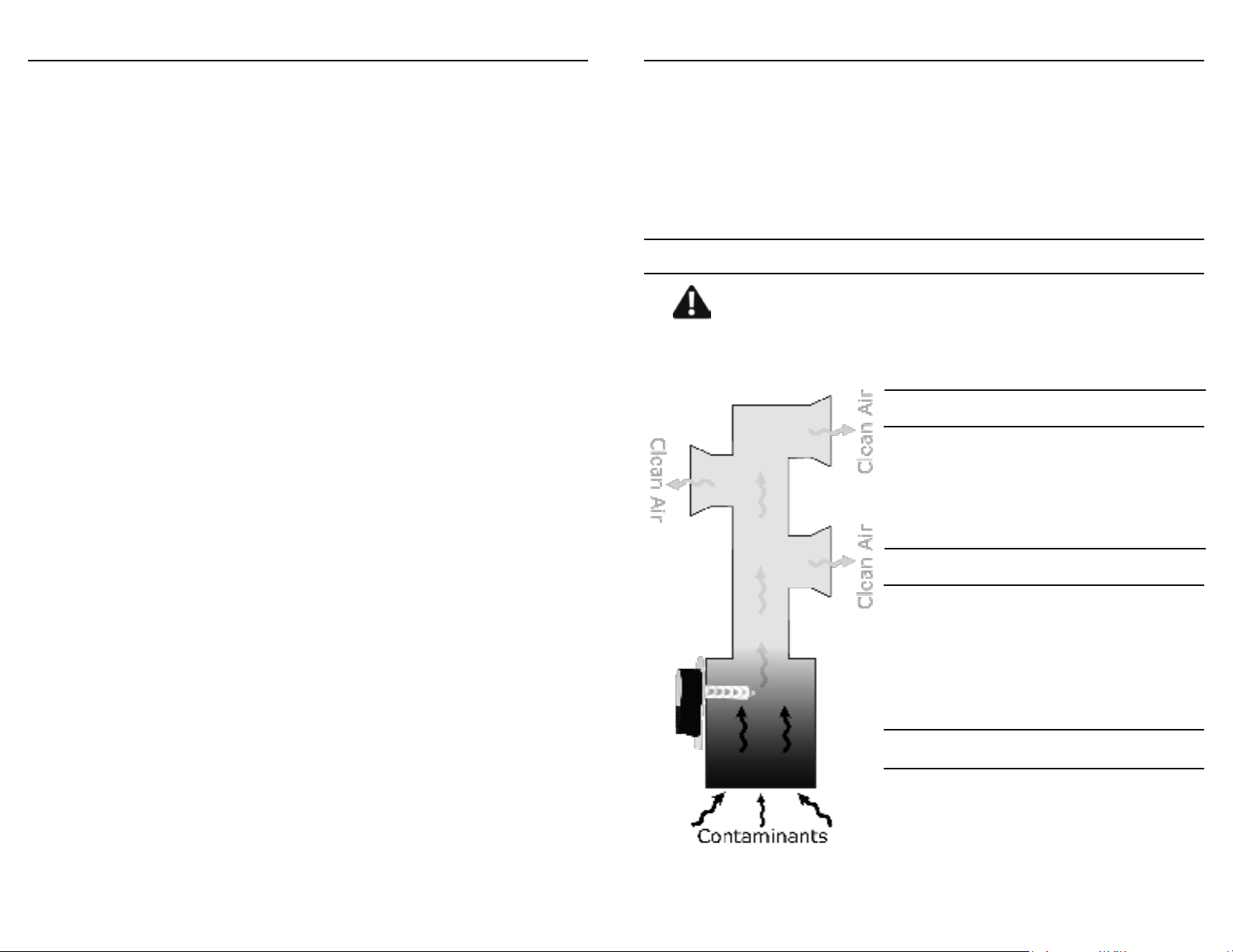
The puriers can be installed on either the return or supply side of the
plenum.
Step 1
Cut a 3”x5” hole in the plenum using a jig
saw. Make sure the hole is centered so
that no part of the mounting plate is hanging off the edges of the plenum when the
probe is inserted.
Air Oasis’ liability for damages to you for any costs whatsoever arising out of this
statement of limited warranty shall be limited to the amount paid for this product
at the time of original purchase, and Air Oasis shall not be liable for any direct,
indirect, consequential or incidental damages arising out of the use or inability to
use this product.
ALL EXPRESS AND IMPLIED WARRANTIES FOR THIS PRODUCT, INCLUDING IMPLIED WARRANTIES OF MERCHANTABILITY AND FITNESS FOR A
PARTICULAR PURPOSE, ARE LIMITED IN DURATION TO THE WARRANTY
PERIOD, AND NO WARRANTIES, WHETHER EXPRESS OR IMPLIED, WILL
APPLY AFTER THIS PERIOD.
Some states do not allow limitations on the duration of implied warranties, so
the above limitation may not apply to you. This warranty gives you specic legal
rights, and you may also have other rights which vary from state to state.
To obtain warranty service and return authorization number, contact us at:
PH: (800) 936-1764, FAX: (806) 373-7799 or E-mail to [email protected]
NOTE: All returned packages that do not have an RMA# will be refused.
3
Step 2
Insert the probe into the 3”x5” hole until the
back mounting plate is ush against the
plenum surface. We recommend mounting
the unit with the rectangular side facing either left or right, but not down or up.
Step 3
Attach the mounting plate to the plenum
surface using sheet metal screws. There
are predrilled holes on the mounting plate
that can be used as a guide. It’s recommended to seal the edges of the mounting
plate using aluminum insulation tape.
4
 Loading...