

Page 1
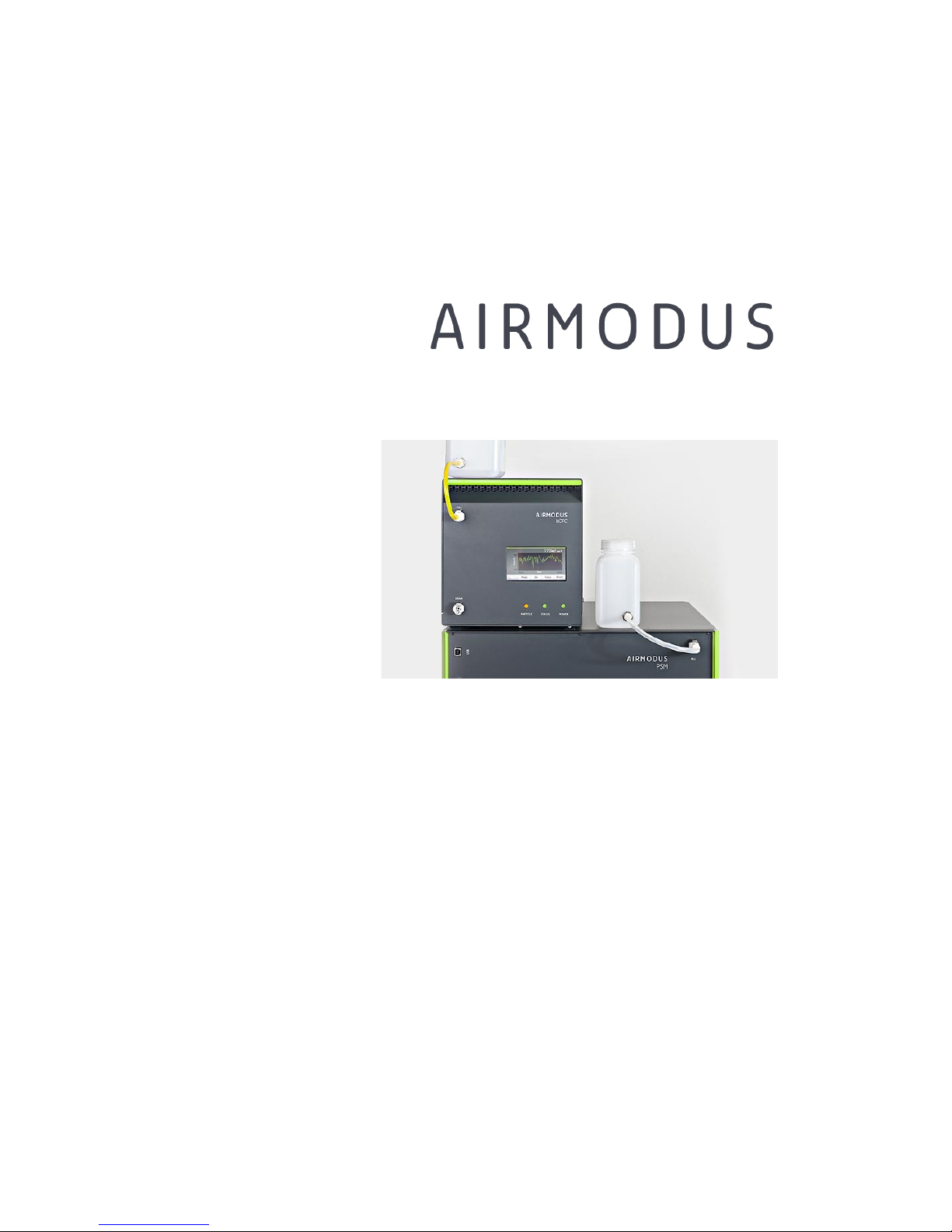
nano Condensation Nucleus Counter system
MODEL A11 nCNC
USER MANUAL
Version 1.94
© 2017 Airmodus Ltd
Page 2

AIRMODUS A11 nCNC USER MANUAL Page 2
Ref. A13TD0015
Version 1.94 Document date: 18.08.2017
© 2017 Airmodus Ltd
TABLE OF CONTENTS
1! Warning .................................................................................... 4!
2! Limitation of Warranty and Liability .............................................. 5!
3! Safety ...................................................................................... 7!
4! nano Condensation Nucleus Counter – Introduction ........................ 8!
4.1! Introduction ......................................................................... 8!
4.2! Operation Principle of the PSM ............................................... 9!
4.3! Operation Principle of the CPC ............................................... 10!
5! Instrument descriptions ............................................................. 12!
5.1! PSM front Panel ................................................................... 12!
5.2! PSM back panel ................................................................... 13!
5.3! CPC Front Panel .................................................................. 14!
5.4! CPC Back panel ................................................................... 15!
5.5! A1X Software ...................................................................... 16!
6! Getting Started ......................................................................... 18!
6.1! Unpacking .......................................................................... 18!
6.2! Setting up the instrument ..................................................... 19!
6.2.1! Installation of DEG drip bottle for Airmodus PSM ................ 20!
6.3! Installing A1X Software ........................................................ 21!
6.4! Before starting the software for the first time .......................... 23!
6.5! Starting the measurements ................................................... 25!
7! Operation and Maintenance ........................................................ 30!
7.1! Working with the nCNC ........................................................ 30!
7.2! CPC Operation and maintenance ............................................ 31!
7.2.1! CPC Display and settings ................................................. 31!
7.2.2! Filling, draining and drying butanol of the CPC ................... 33!
7.3! Filling, priming, draining and drying DEG of the PSM ................ 35!
7.3.1! Filling ........................................................................... 35!
7.3.2! Priming ......................................................................... 35!
7.3.3! Draining and drying ........................................................ 36!
7.4! Selecting operation mode ..................................................... 38!
Page 3

AIRMODUS A11 nCNC USER MANUAL Page 3
Ref. A13TD0015
Version 1.94 Document date: 18.08.2017
© 2017 Airmodus Ltd
7.4.1! Fixed cut-off .................................................................. 39!
7.4.2! Stepping mode .............................................................. 40!
7.4.3! Scanning ...................................................................... 42!
7.5! Operation environment and safety ......................................... 44!
7.6! Communication ................................................................... 45!
7.7! Data management and saving data ........................................ 46!
7.7.1! Raw data file ................................................................. 48!
7.7.2! Inverted scanning data ................................................... 51!
7.8! Verifying flows .................................................................... 52!
7.9! Moving and shipping the nCNC .............................................. 53!
7.10! Efficiency & Response time ................................................ 53!
7.11! Replacement Parts ............................................................ 54!
7.12! Flooding of the Instrument ................................................. 54!
7.13! Calibration ....................................................................... 54!
7.14! How to get help / Technical contacts ................................... 55!
8! Troubleshooting ........................................................................ 56!
APPENDIX 1 – A11 nCNC Specifications ............................................. 58!
APPENDIX 2 – PSM Firmware commands ........................................... 60!
Read / system Commands ............................................................ 60!
Commands handled in all states .................................................. 60!
Commands handled only in standby mode .................................... 60!
Commands handled only in run mode .......................................... 61!
Status Commands ....................................................................... 61!
Set Commands ............................................................................ 64!
APPENDIX 3 – Airmodus bCPC Serial Commands, v1.6.0 ...................... 67!
APPENDIX 4 – References ................................................................ 72!
Page 4

AIRMODUS A11 nCNC USER MANUAL Page 4
Ref. A13TD0015
Version 1.94 Document date: 18.08.2017
© 2017 Airmodus Ltd
1 Warning
THE PRODUCTS OF AIRMODUS LTD. ARE NOT INTENDED TO BE USED
NOR DESIGNED WITH COMPONENTS AND TESTING SUITABLE FOR USE IN
THE DIAGNOSIS AND TREATMENT OF HUMANS OR AS CRITICAL
COMPONENTS IN ANY LIFE SUPPORT SYSTEMS WHOSE FAILURE TO
PERFORM CAN REASONABLY BE EXPECTED TO CAUSE INJURY TO A
HUMAN.
RELIABILITY OF OPERATION OF ANY SOFTWARE CAN BE IMPAIRED BY
ADVERSE FACTORS, INCLUDING BUT NOT LIMITED TO FLUCTUATIONS IN
ELECTRICAL POWER SUPPLY, COMPUTER HARDWARE MALFUNCTIONS,
COMPUTER OPERATING SYSTEM SOFTWARE FITNESS, FITNESS OF
COMPILERS OR DEVELOPMENT SOFTWARE USED TO DEVELOP AN
APPLICATION, INSTALLATION ERRORS, SOFTWARE AND HARDWARE
COMPATIBILITY PROBLEMS, MALFUNCTIONS OR FAILURES OF
ELECTRONIC MONITORING OR CONTROL DEVICES, TRANSIENT FAILURES
OF ELECTONIC SYSTEMS (HARDWARE AND/OR SOFTWARE),
UNANTICIPATED USES OR MISSUSES, OR ERRORS ON THE PART OF THE
USER OR APPLICATION DESIGNER. (ADVERSE FACTORS SUCH AS THESE
ARE HEREAFTER COLLECTIVELY TERMED SYSTEM FAILURES) ANY
APPLICATION WHERE A SYSTEM FAILURE WOULD CREATE A RISK OF
HARM TO PROPERTY OR PERSONS (INCLUDING THE RISK OF BODILY
INJURY AND DEATH) SHOULD NOT BE RELIANT SOLELY UPON
ELECTRONIC MONITORING DUE TO THE RISK OF SYSTEM FAILURE. TO
AVOID DAMAGE, INJURY OR DEATH, THE USER OR APPLICATION
DESIGNER MUST TAKE REASONABLY PRUDENT STEPS TO PROTECT
AGAINST SYSTEM FAILURES, INCUDING BUT NOT LIMITED TO BACK-UP
OR SHUT DOWN MECHANISMS.
Page 5

AIRMODUS A11 nCNC USER MANUAL Page 5
Ref. A13TD0015
Version 1.94 Document date: 18.08.2017
© 2017 Airmodus Ltd
2 Limitation of Warranty and Liability
Seller warrants that the goods delivered, under normal use and service as
described in the User Manual, shall be free of defects in workmanship and
material for a period of 12 months, or the length of time specified in the
User Manual, from the date of shipment to the customer. This limited
warranty is subject to the following exclusions:
• With respect to any repair services rendered, Seller warrants that
the parts repaired or replaced will be free of defects in
workmanship and material, under normal use, for a period of 90
days from the date of shipment to the customer;
• Seller does not provide any warranty on finished goods
manufactured by others or on any fuses, filters, batteries or other
consumable materials. Only the original manufacturer's warranty
applies;
• Unless specifically authorized in writing by Seller, Seller makes no
warranty with respect to, and shall have no liability in connection
with, any goods, which are incorporated into other products or
equipment or which are modified by any person other than the
Seller. This applies also e.g. to particle counters connected to
Airmodus particle size magnifiers: Airmodus has no liability in
connection with the integrated system unless the whole system is
delivered by Airmodus;
• All goods returned under warranty shall be at the customer’s risk of
loss and the customer shall cover the costs of transportation
(freight, insurance, etc.). The goods will be returned, if at all, at
Seller's risk of loss.
The foregoing is IN LIEU OF all other warranties and is subject to the
conditions and LIMITATIONS stated herein. NO OTHER EXPRESS OR
IMPLIED WARRANTY OF FITNESS FOR PARTICULAR PURPOSE OR
MERCHANTABILITY IS MADE.
THE EXCLUSIVE REMEDY OF THE USER OR PURCHASER, AND THE LIMIT
OF THE LIABILITY OF SELLER FOR ANY AND ALL LOSSES, INJURIES, OR
DAMAGES IN CONNECTION WITH THIS PRODUCT (INCLUDING CLAIMS
Page 6

AIRMODUS A11 nCNC USER MANUAL Page 6
Ref. A13TD0015
Version 1.94 Document date: 18.08.2017
© 2017 Airmodus Ltd
BASED ON CONTRACT, NEGLIGENCE, STRICT LIABILITY, OTHER TORT,
OR OTHERWISE) SHALL BE RETURN OF THE PRODUCT TO THE FACTORY
OR DESIGNATED LOCATION AND THE REFUND OF THE PURCHASE PRICE,
OR, AT THE OPTION OF SELLER, THE REPAIR OR REPLACEMENT OF THE
PRODUCT.
IN NO EVENT SHALL SELLER BE LIABLE FOR ANY SPECIAL, INCIDENTAL
OR CONSEQUENTIAL DAMAGES. SELLER SHALL NOT BE RESPONSIBLE
FOR INSTALLATION, DISMANTLING, REASSEMBLY OR REINSTALLATION
COSTS OR CHARGES. NO ACTION REGARDLESS OF FORM CAN BE
BROUGHT AGAINST SELLER, MORE THAN ONE YEAR AFTER THE CAUSE
OF ACTION HAS OCCURRED.
Buyer and all users are deemed to have accepted this LIMITATION OF
WARRANTY AND LIABILITY, which contains the complete and exclusive
limited warranty of Seller. This LIMITATION OF WARRANTY AND LIABILITY
may not be amended, modified or its terms waived, except by writing
signed by an authorized representative of Seller.
Page 7
AIRMODUS A11 nCNC USER MANUAL Page 7
Ref. A13TD0015
Version 1.94 Document date: 18.08.2017
© 2017 Airmodus Ltd
3 Safety
Warning: This measurement system uses diethylene glycol and n-
butanol as working fluids. Diethylene glycol is toxic and hazardous in case
of skin contact (irritant, permeator), of eye contact (irritant), of ingestion
and of inhalation. See the material safety data sheet of diethylene glycol.
Butanol is a flammable solvent and can be toxic when inhaled (see
material safety data sheet of n-butanol). Proper air extraction should be
used to avoid exposure to Butanol vapour or a suitable filter should be
used. The room where the instrument is used should be properly
ventilated.
Warning: Do not open the covers of the instrument, when it is
connected to a power supply. Risk of electric shock or exposure to high
temperature parts/liquid can occur if the covers are opened during
operation of the instrument.
Warning: Take care and use safety goggles when connecting the
instrument to compressed air line.
Warning: The CPC is a class I laser product. Exposure to the
laser can cause blindness. In normal operation, the user is not exposed to
the laser radiation. Do not remove the cover of the instrument when
power is supplied and do not modify or remove any parts of the
instrument.
Page 8
AIRMODUS A11 nCNC USER MANUAL Page 8
Ref. A13TD0015
Version 1.94 Document date: 18.08.2017
© 2017 Airmodus Ltd
4 nano Condensation Nucleus Counter –
Introduction
4.1 Introduction
The nano Condensation Nucleus Counter system consists of a Particle Size
Magnifier (PSM) and a Condensation Particle Counter (CPC). The PSM is
an aerosol pre-conditioner that grows aerosol particles as small as 1 nm
up to about 90 nm in mobility equivalent diameter, after which they are
further grown to optical sizes and counted in the CPC. By using the PSM
together with the CPC even single large molecules or molecular clusters
can be detected.
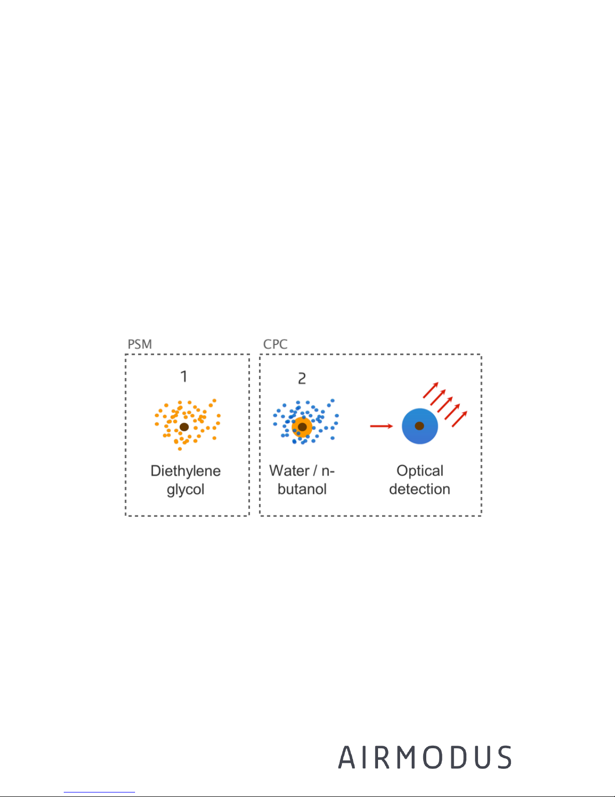
Figure 4-1 The idea of dual-stage condensation in the nano
Condensation Nucleus Counter system. Stage 1, particle growth
with diethylene glycol condensation is done in the PSM, whereas
stage 2 and detection is done by an external counter CPC.
The use of the Particle Size Magnifier is based on using a proper
condensing fluid for activating also the smallest particles. With diethylene
glycol as the condensing fluid, the PSM can be used at high
supersaturations without substantial homogenous nucleation of the
Page 9

AIRMODUS A11 nCNC USER MANUAL Page 9
Ref. A13TD0015
Version 1.94 Document date: 18.08.2017
© 2017 Airmodus Ltd
working fluid. Since diethylene glycol can grow the particles only to about
90 nm in diameter, a CPC using butanol as condensing fluid is needed as a
second stage for further growing the particles to optical sizes, and for
detection.
The technique can be used for both charged and neutral particles without
the need for pre-charging the aerosol. Theoretically charged particles may
activate easier than neutral ones. Also the chemical composition of the
particles can somewhat affect the activation probability.
The nCNC has three measurement modes: 1) In the fixed flow mode it
gives the total concentration at one user-selectable saturator flow rate
corresponding to a certain cut-off size, 2) in stepping mode the user can
select up to 4 different saturator flow rates for the instrument and thus
periodically monitor the total concentration at different cut-off sizes, 3) in
scanning mode the saturator flow rate is changed continuously, giving an
activation spectrum of the measured particles, which can be used e.g. to
obtain size or composition information of the ~1-4 nm particles.
NOTE: the diffusional losses of particles smaller than 4 nm can be
substantial. Therefore, use as short inlet tube as possible before the PSM,
or use make-up flow.
4.2 Operation Principle of the PSM
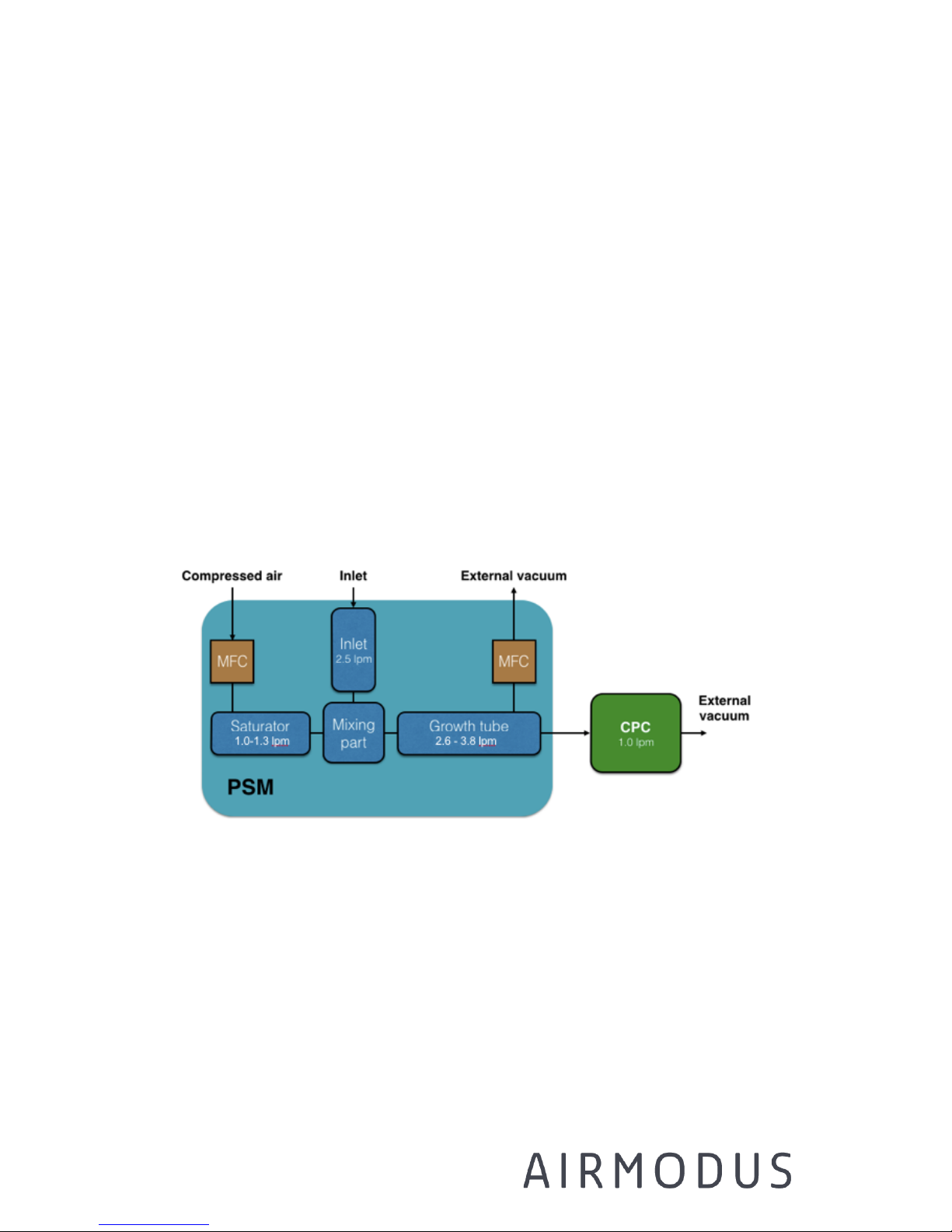
The PSM consists of a saturator, mixing region and growth tube (Figure
Figure 4-2). Clean air is led through the saturator where it is heated and
exposed to diethylene glycol, which vaporizes to the flow. The aerosol flow
sampled trough the inlet is turbulently mixed with the saturator flow in
the cooled mixing region. As the flow cools down, the diethylene glycol
reaches supersaturation, and starts condensing on the particles. After the
mixing region, the sample is led to a cooled growth tube, where the
particles continue growing, when diethylene glycol is condensing on them.
Page 10
AIRMODUS A11 nCNC USER MANUAL Page 10
Ref. A13TD0015
Version 1.94 Document date: 18.08.2017
© 2017 Airmodus Ltd
After the PSM a part of the flow is led to the CPC, and part of the flow is
discarded as excess flow.
Please note: The flows of the PSM are controlled as mass flow and
converted to volumetric flow (@20oC and 101.3kPa).
The cut-off diameter of the nCNC can be easily adjusted programmatically
by changing the saturator flow rate in the PSM. This changes the mixing
ratio of the inlet and saturator flow, which determines the supersaturation
inside the mixing region and growth tube. The supersaturation, in turn,
determines how small particles can be activated.
For details of how to define the cut-off diameter see Chapter Calibration
on page 54.
Figure 4-2 Schematics of the PSM, showing the saturator, the
mixing region, the growth tube and the CPC.
4.3 Operation Principle of the CPC
The A20 Condensation Particle Counter is intended for measuring the
number concentration of airborne solid or liquid particles (aerosol
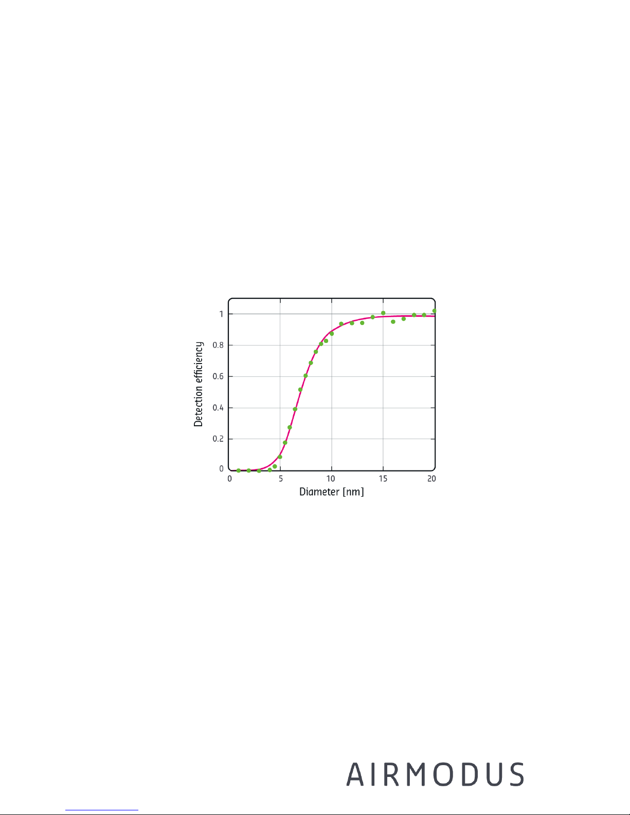
particles) in the size range of 7 nm – 2.5 μm (see figure 4-3). It can be
Page 11
AIRMODUS A11 nCNC USER MANUAL Page 11
Ref. A13TD0015
Version 1.94 Document date: 18.08.2017
© 2017 Airmodus Ltd
used independently for measuring the total particle concentration, or as a
counter in various aerosol measurement systems.
The condensing fluid in A20 is n-butanol. The supersaturation required for
condensation is achieved by cooling warm air saturated with butanol until
the vapour starts to condense on particles. The resulting droplets are
detected individually in the optics based on the light they scatter. The
A20 is working in the single-particle measurement mode in the
concentration range from 0-30 000/cc, and concentrations up to 1e5/cc
can be measured when a correction function is applied. At higher
concentrations a dilution system is needed.
Figure 4-3 Example of the detection efficiency curve of the A20.
Page 12
AIRMODUS A11 nCNC USER MANUAL Page 12
Ref. A13TD0015
Version 1.94 Document date: 18.08.2017
© 2017 Airmodus Ltd
5 Instrument descriptions
The A11 nCNC system consists of an A10 PSM and an A20 CPC, together
with the A1X operating software.
5.1 PSM front Panel
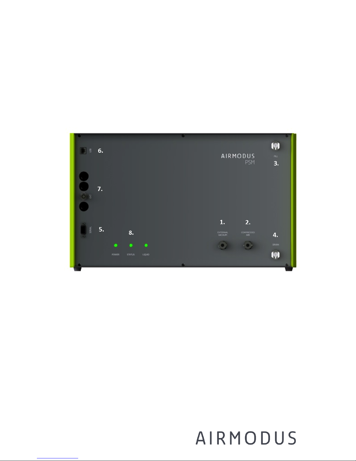
Figure 5-1 Front panel of the PSM
1. Connection for external vacuum. 100 - 350 mbar is needed (in NTP)
2. Connection for compressed air. 1.5 – 2.5 bar is needed (NTP). !!!
NOTE, DON’T EXCEED THE MAXIMUM WORKING PRESSURE OF 3.0
BAR !!!
3. Connection for DEG fill bottle.
4. Connection for DEG drain bottle
5. Serial RS-232 connection
Page 13
AIRMODUS A11 nCNC USER MANUAL Page 13
Ref. A13TD0015
Version 1.94 Document date: 18.08.2017
© 2017 Airmodus Ltd
6. USB 2.0 connection
7. Programmable 0-10 V analogue output connection (a BNC
connector). Can be used to control e.g. an Ion filter or a DMA.
8. Power, status and drain LEDs – should be green when instrument is
working properly
5.2 PSM back panel
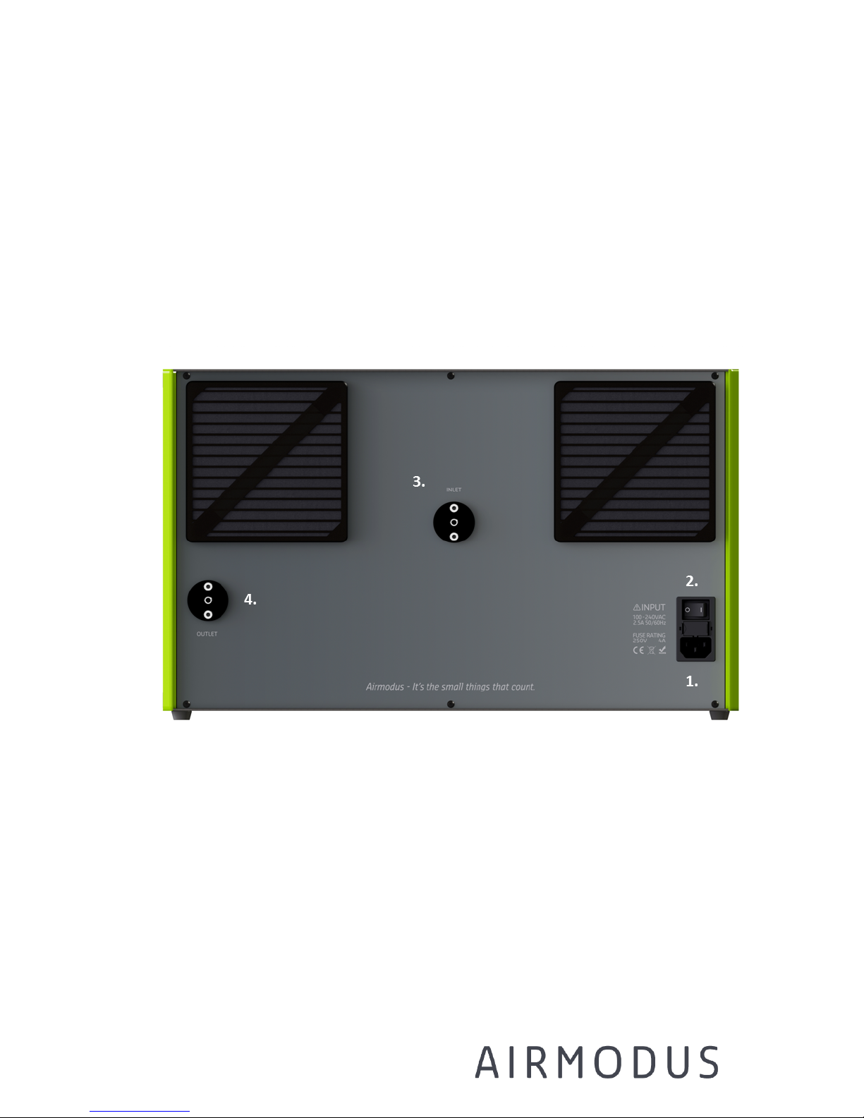
Figure 5-2 Back panel of the PSM
1. Connection for power cable (100 - 240 VAC, max 320 W)
2. Power switch
3. Particle inlet, 1/4 inch
4. Particle outlet, 1/4 inch – connect this to the counter CPC using the
black sampling line provided with the system.
Page 14
AIRMODUS A11 nCNC USER MANUAL Page 14
Ref. A13TD0015
Version 1.94 Document date: 18.08.2017
© 2017 Airmodus Ltd
5.3 CPC Front Panel
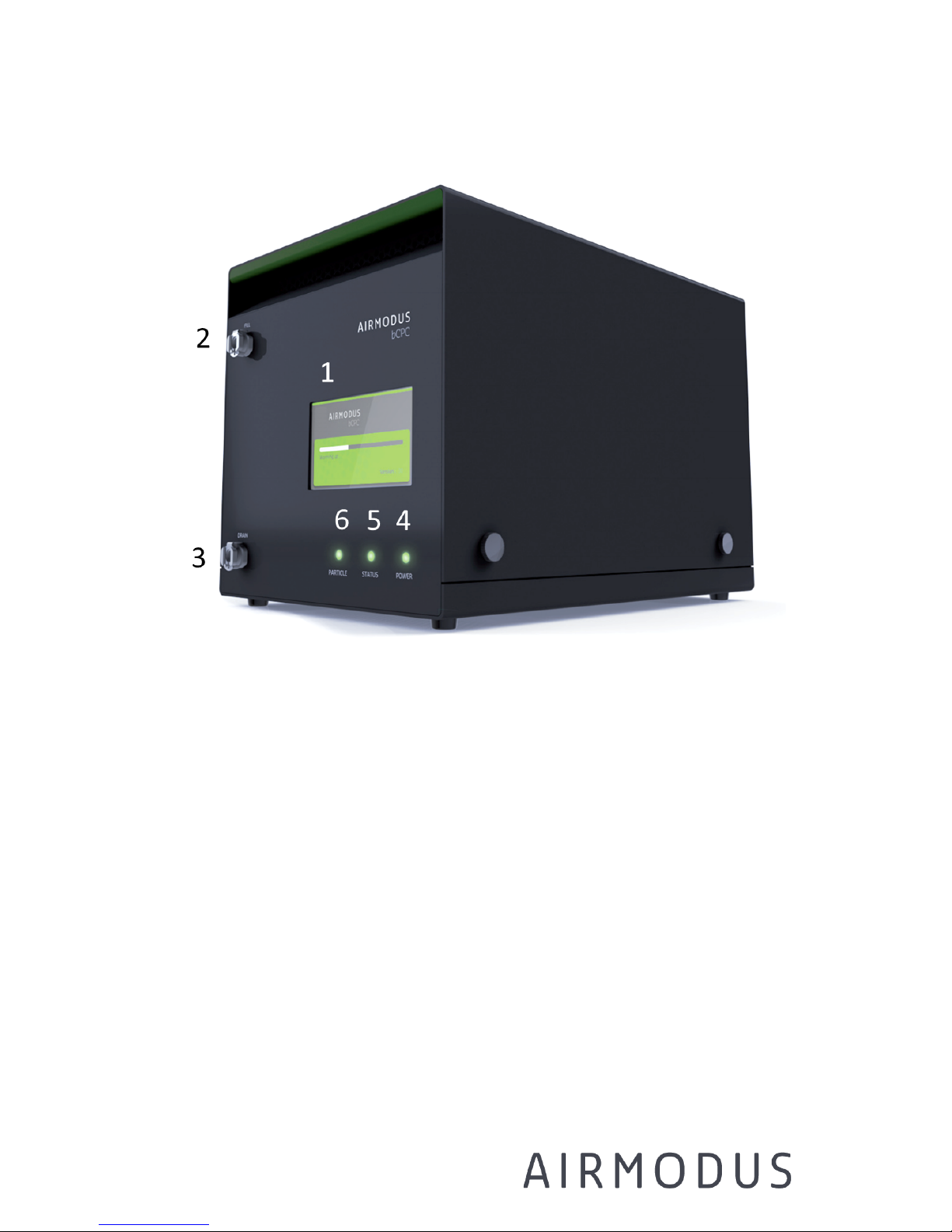
Figure 5-3. A20 Side view.
1. Display
Touch screen for operating the instrument and displaying the
concentration.
2. Fill
The fill bottle for butanol should be connected here.
3. Drain
Connector for draining butanol out of the instrument.
4. Power light
The power light indicates that the instrument is on. The power light
is red if the instrument self-test fails (contact Airmodus).
5. Status light
The status light indicates that all the operation parameters (e.g.
Page 15
AIRMODUS A11 nCNC USER MANUAL Page 15
Ref. A13TD0015
Version 1.94 Document date: 18.08.2017
© 2017 Airmodus Ltd
temperatures) of the instrument have reached correct values.
Status light is green, when everything is ok, and red if any of the
settings are out-of-range. Status light is yellow when instrument is
in warm-up mode.
6. Particle light
Particle light is lit when particles are being detected.
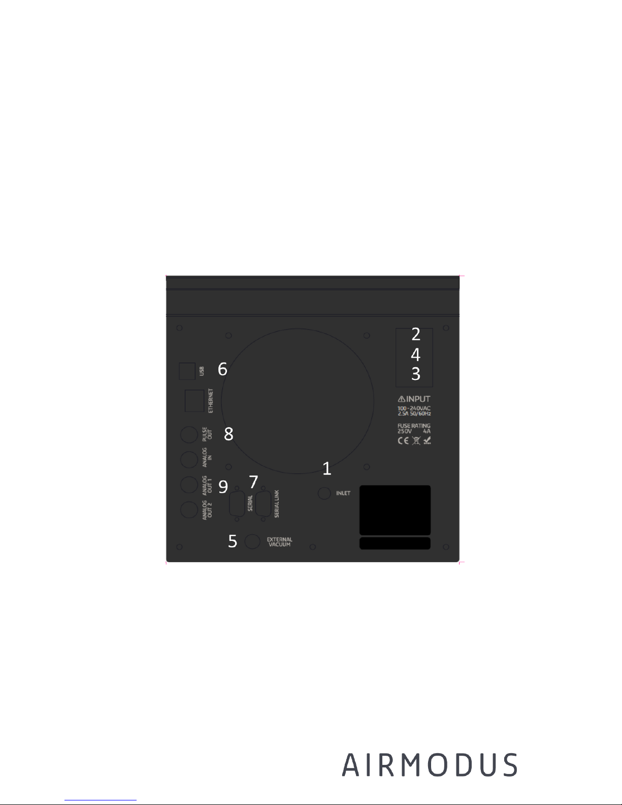
5.4 CPC Back panel
Figure 5-4. A20 Back panel
1. Inlet
The inlet of the A20 is a ¼ inch stainless steel tube. Inlet flow rate
is 1 lpm.
2. Power switch
For switching the instrument on and off.
Page 16
AIRMODUS A11 nCNC USER MANUAL Page 16
Ref. A13TD0015
Version 1.94 Document date: 18.08.2017
© 2017 Airmodus Ltd
3. Power cord
Connection for the power cord.
4. Fuse
Fuse rating is 250 V, 4 A.
5. Connection for external vacuum
The instrument needs to be connected to a pump or external
vacuum for maintaining the flow rate. The vacuum source should be
enough to maintain a critical flow of 1 l/min. The exhaust air may
contain some butanol vapour.
Warning: Butanol vapours should be led out of breathing air or a
suitable filter should be used. Butanol is a flammable solvent and can be
toxic when inhaled (see material safety data sheet of n-butanol).
6. USB and Ethernet
Connections for communicating with external devices
7. Serial and Serial link
Connections for communicating with external devices
8. Pulse out
Gives out a 5 V TTL-pulse for each detected particle.
9. Analog in/out
Programmable 0-10V analog voltage input/outputs.
5.5 A1X Software
The A11 nCNC includes software, which can be installed to a computer
(Microsoft Windows only). The software can be used for setting and
monitoring the PSM and CPC status and parameters, changing the
measurement mode, and displaying and saving data from the nCNC. The
A1X software also provides in-situ inversion of the measured data when
used with Airmodus CPC: based on calibration information a size
distribution is calculated for 1-4 nm particles. Please note that the given
Page 17

AIRMODUS A11 nCNC USER MANUAL Page 17
Ref. A13TD0015
Version 1.94 Document date: 18.08.2017
© 2017 Airmodus Ltd
size is based on Nickel Chromium calibration and thus is given as Nickel
Chromium equivalent diameter, for other particle compositions the
activation spectra may represent other sizes.
Page 18
AIRMODUS A11 nCNC USER MANUAL Page 18
Ref. A13TD0015
Version 1.94 Document date: 18.08.2017
© 2017 Airmodus Ltd
6 Getting Started
6.1 Unpacking
Warning: Check that the box is upwards from the side arrow
stickers before opening.
The A11 nCNC shipment contains two boxes. Each box contains an
instrument mounted on foam cushions, and a smaller box containing
accessories (e.g. the sample PSM-CPC tube), manual, calibration
certificate and fill- and drain bottles.
First remove the accessories box, manual and calibration certificate and
after that carefully pull the instrument from the cardboard box. Remove
the end cushions.
If the instrument has been transported in temperatures considerably
lower than room temperature, store it in room temperature for two hours
before starting to operate with it.
After unpacking, the instruments are ready for setting up.
Page 19
AIRMODUS A11 nCNC USER MANUAL Page 19
Ref. A13TD0015
Version 1.94 Document date: 18.08.2017
© 2017 Airmodus Ltd
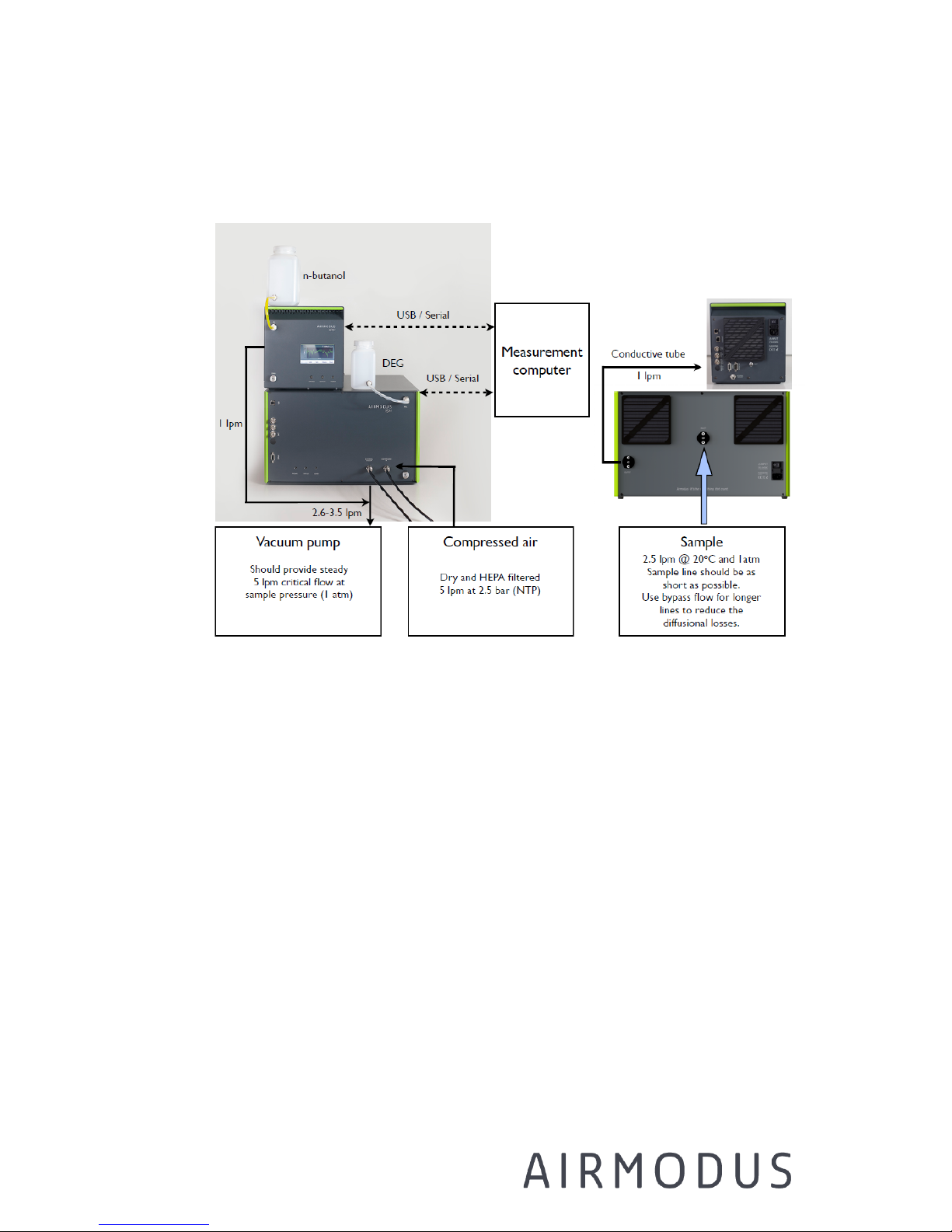
6.2 Setting up the instrument
Figure 6-1 Set-up of the A11
1. Attach the power cables to the PSM and the CPC.
2. Connect vacuum and pressurized air to the PSM front panel and
vacuum to the CPC back panel (see Figure 6-1)
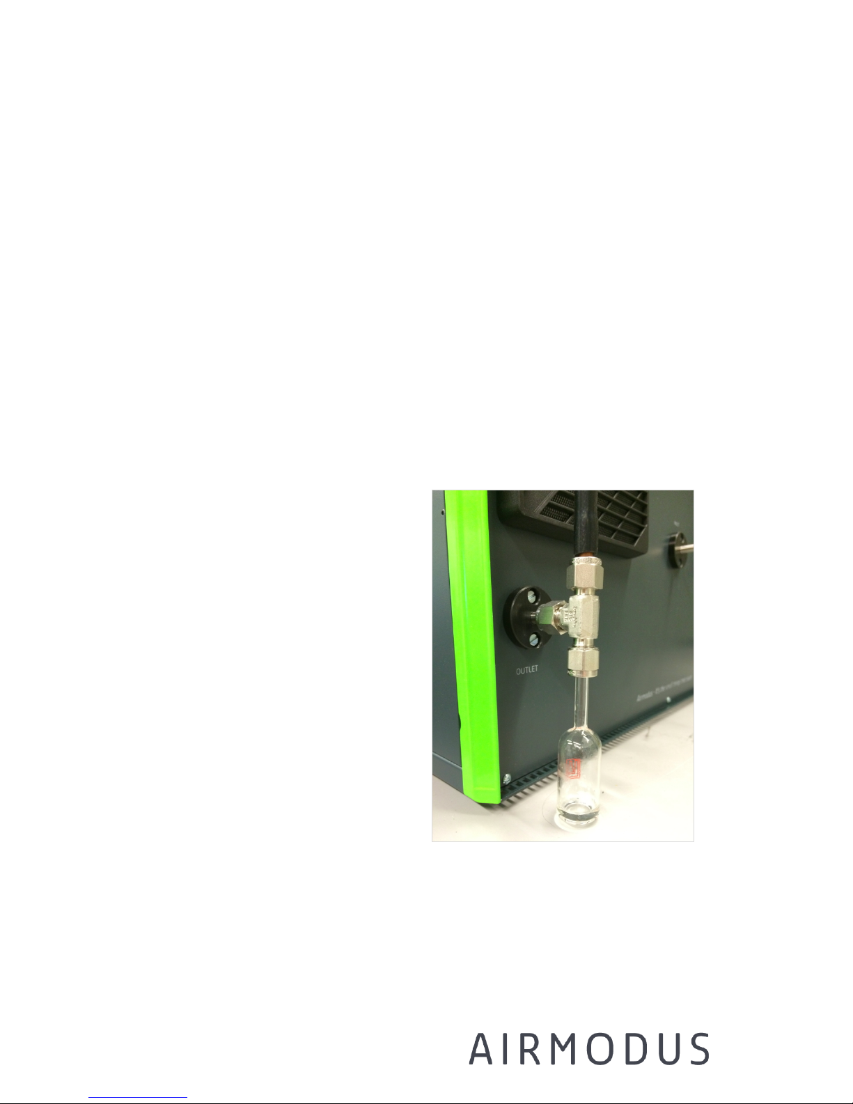
3. Connect the PSM aerosol outlet to the Drip Bottle (see instructions
and the figure in Chapter 6.2.1) and then to the CPC inlet with
conductive tubing. A 45 cm tube is delivered with the instrument,
please note that the length of the tube affects the response time of
the complete system. The CPC should be preferably placed on a
higher level than the PSM outlet, for example on top of the PSM.
4. Connect the fill bottle with DEG (diethylene glycol) to the PSM front
panel “LIQUID IN” connector. Make sure that there is a hole in the
cap of the fill bottle, or that the cap is slightly open, to ensure
pressure stabilization inside the bottle.
Page 20
AIRMODUS A11 nCNC USER MANUAL Page 20
Ref. A13TD0015
Version 1.94 Document date: 18.08.2017
© 2017 Airmodus Ltd
5. Connect the fill bottle with butanol to the CPC. Make sure that there
is a hole in the cap of the fill bottle, or that the cap is slightly open,
to ensure pressure stabilization inside the bottle.
6. Connect the PSM and CPC to a computer with USB or serial cable
7. Switch on the power of the PSM and the CPC.
8. Let the CPC run for 20 minutes and then check the CPC inlet flow
(preferably in-line, but do note that the sample leaving the PSM
contains DEG). Set the measured flow rate into the Before starting
tab of the measurement software.
9. Connect the sample inlet of the PSM.
6.2.1 Installation of DEG drip bottle for Airmodus PSM
PSM uses diethylene glycol (DEG)
to grow aerosol particle. The
growth is achieved by condensing
DEG vapour on top of the aerosol
particle. After the condensational
growth stage inside the PSM there
can be some excess DEG vapour
still in the sample air. This excess
vapour can condense on the walls
of the tube that is connected to the
inlet of the CPC. In order to prevent
this condensing DEG from getting
inside the CPC a drip bottle should
be installed (see figure).
Page 21
AIRMODUS A11 nCNC USER MANUAL Page 21
Ref. A13TD0015
Version 1.94 Document date: 18.08.2017
© 2017 Airmodus Ltd
6.3 Installing A1X Software
NOTE: have the instruments on and connected to your computer before
installing the software. We recommend that the computer is connected to
internet when installing the software for the first time.
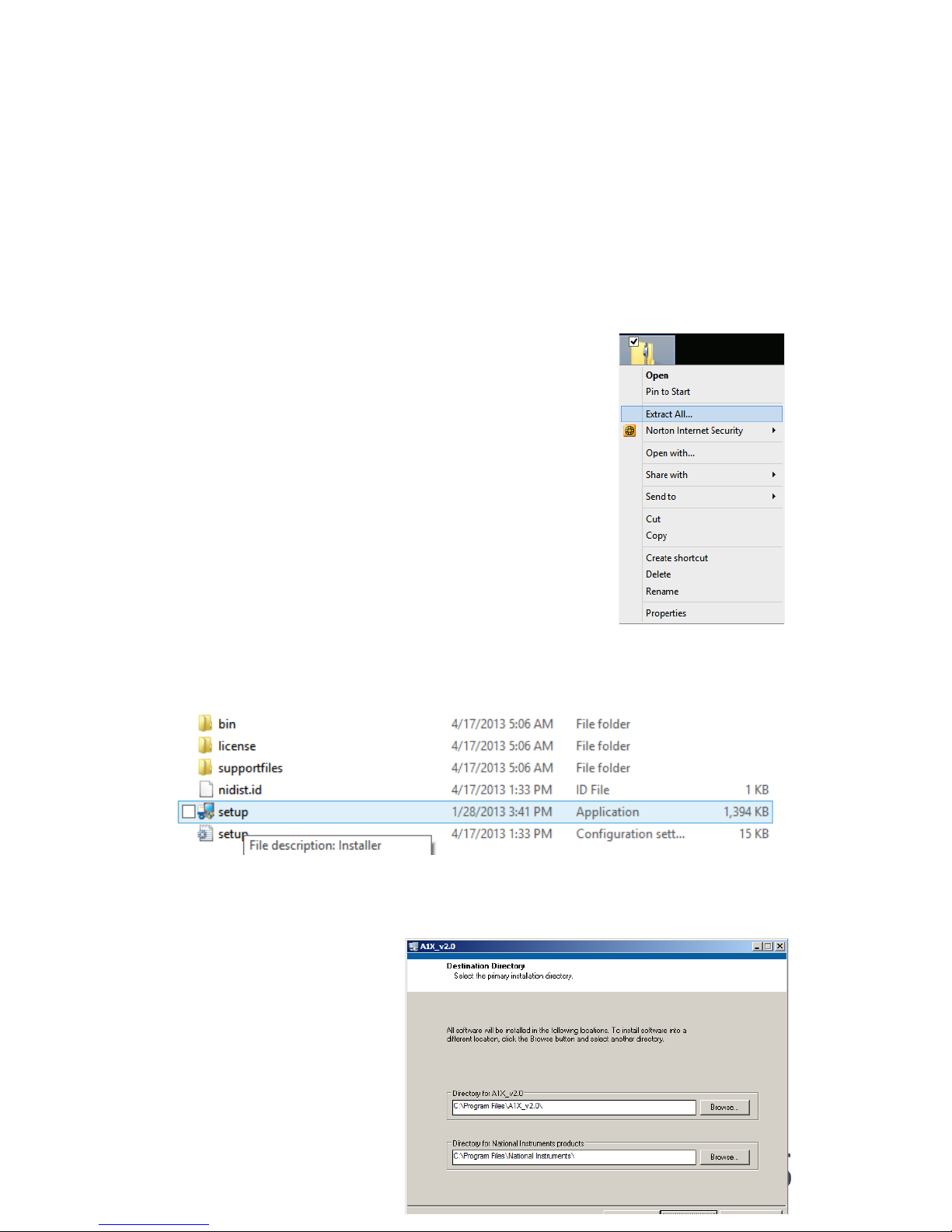
Copy the A1X zip-file on your computer and extract the file following the
instructions below.
Extract the zip file by right-clicking it. Choose extract
all and select destination folder. Make sure you have
writing access to the destination folders.
After extraction is completed, go to the destination folder, find setup file
and double click it.
Page 22
AIRMODUS A11 nCNC USER MANUAL Page 22
Ref. A13TD0015
Version 1.94 Document date: 18.08.2017
© 2017 Airmodus Ltd
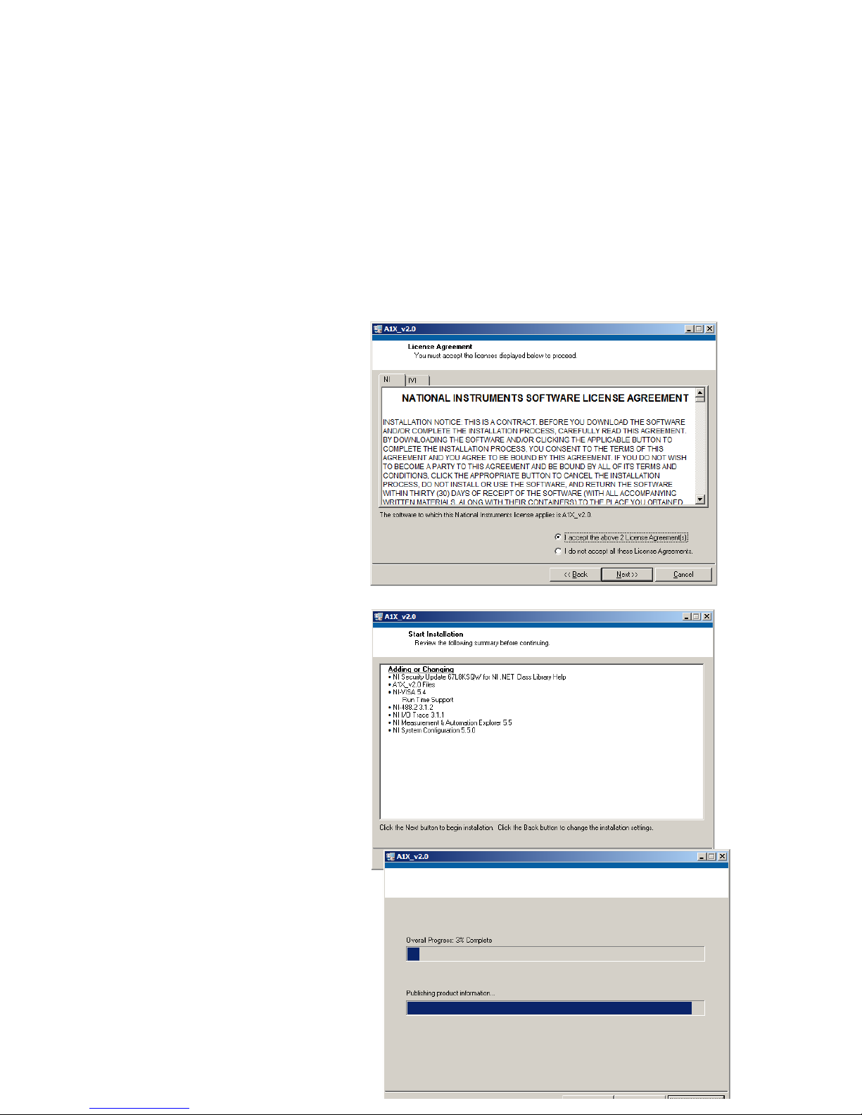
Select the destination directories (make sure you have writing access) and
click next.
Accept both of the National
Instruments software
licenses and click next.
This dialog shows which
software components will
be installed to the
computer. Click next.
Page 23
AIRMODUS A11 nCNC USER MANUAL Page 23
Ref. A13TD0015
Version 1.94 Document date: 18.08.2017
© 2017 Airmodus Ltd
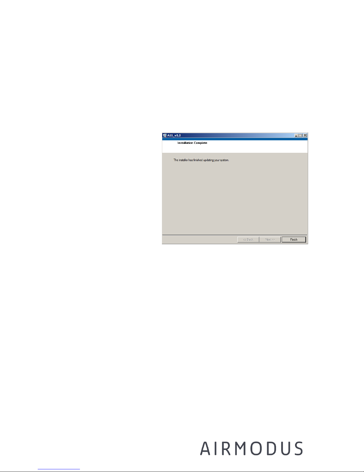
Wait for the installation process to finish. After software installation is
finished, click Finish button
The computer still needs to
be restarted to finish the
installation. After restart the
A1X software is fully
installed.
6.4 Before starting the software for the first time
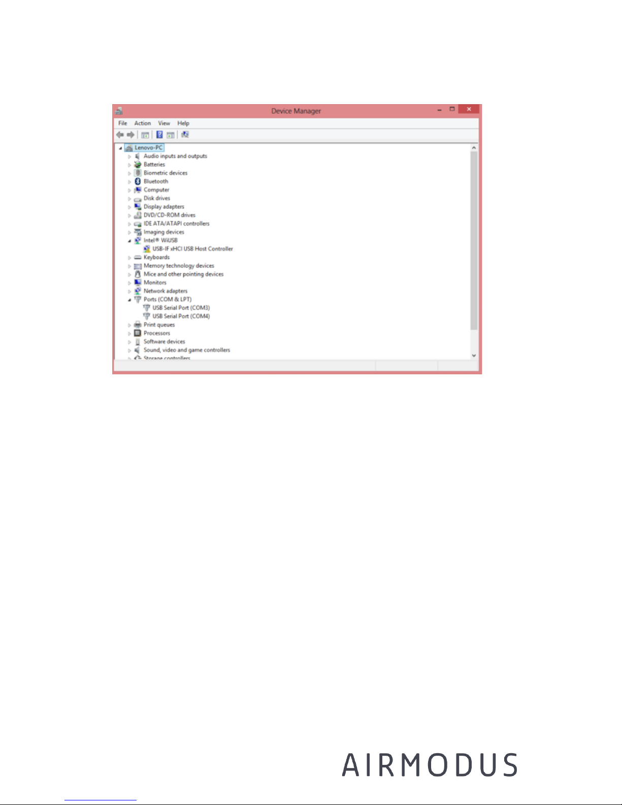
Before starting the software for the first time, find out which USB Serial
ports are used by the CPC and PSM. This can be done from the Windows
Device Manager. Ensure that PSM and CPC are running. After the Device
Manager is opened, connect the CPC and PSM cables to PC:s USB ports.
Corresponding COM ports will appear to the Device Managers Ports listing.
Page 24
AIRMODUS A11 nCNC USER MANUAL Page 24
Ref. A13TD0015
Version 1.94 Document date: 18.08.2017
© 2017 Airmodus Ltd
Go to the directory where the software is installed and open
psmconfig.ini file with a text editor (format of the file is shown below)
-----------------------------------------------------------------
C:\DATA (Data folder)
measurement (Data filename)
COM1 (PSM serial port)
COM2 (CPC serial port)
C:\DATA (Calibration data file folder)
CALIBRATION_FILE.txt (Calibration data file name)
1.0 (Measured CPC inlet flow)
1 (Use calibration data 1/0)
1 (CPC selection*)
------------------------------------------------------------------
* CPC selection: 0 = no CPC, 1 = Airmodus A2X, 2 = TSI 3772/3776, 3 = TSI 3010/3025.
Set the COM ports to correspond the ones shown in the Device Manager.
Make sure that the computer uses period as the delimiter (decimal point),
Page 25

AIRMODUS A11 nCNC USER MANUAL Page 25
Ref. A13TD0015
Version 1.94 Document date: 18.08.2017
© 2017 Airmodus Ltd
not comma. Create a folder into which the data files will later be saved to.
[This is to avoid access rights problems in some Windows computers: the
A1X software is a Labview executable, and e.g. in Windows 8 might not
have the needed rights to create folders.]
6.5 Starting the measurements
Switch on the PSM and CPC by pushing the power switches on the back
panels.
The power and liquid / drain indicators should light up green. The status
light will stay yellow. A11 starts reaching the operating temperatures. The
status light will stay yellow until the desired temperatures are reached.
A summary of steps needed to start measurements is listed below. The steps
are explained in more detail in the chapters to follow:
1) Switch on the PSM and the CPC
2) Check the psmconfig – file (see 6.4)
3) Open the A1X software
4)
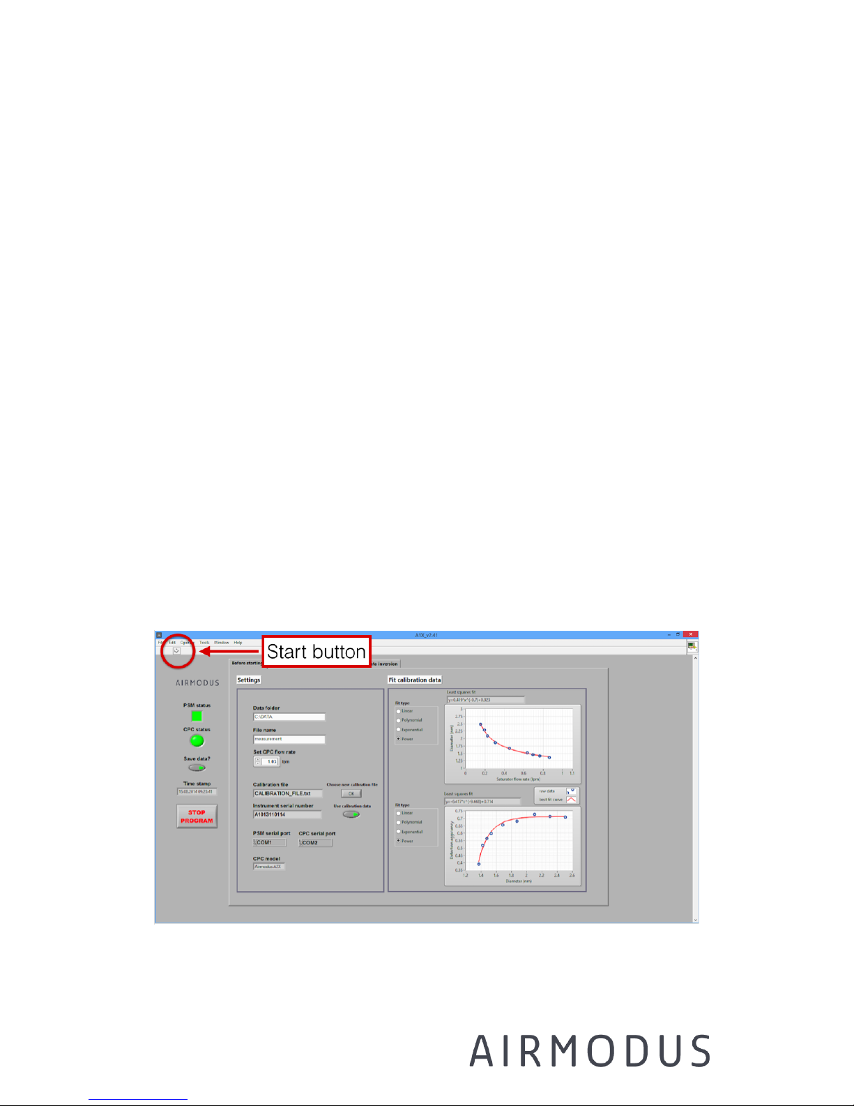
Starts the measurement by pressing the arrow on the upper left
corner
5) Choose the calibration file from the “Before Starting” tab
6)
On the “Before Starting” tab select the best fit to the calibration
data
7) Check flows, temperatures and other status information
8) Measure PSM and CPC inlet flow rates
a. Insert the CPC inlet flow rate to “Before Starting” tab
9) Wait for system status to turn green
10) Select the measurement mode from “Select mode” tab
11) Start saving data by pressing “Save data?” button
Page 26
AIRMODUS A11 nCNC USER MANUAL Page 26
Ref. A13TD0015
Version 1.94 Document date: 18.08.2017
© 2017 Airmodus Ltd
When the temperatures have stabilized the status light will change to
green.
If drain light is continuously red the internal drain reservoir is too full and
needs to be drained. The device will stay in stand-by mode (power light
red) until the liquid level in the internal drain reservoir is low enough (see
instructions for draining the instruments in chapter 7.3). The instrument
needs to be restarted (from power switch) to recover it from stand-by
mode.
Check the psmconfig.ini file for proper settings (see 6.4). Open the A1X
software window. Start the software by pushing the small arrow button on
the upper left corner. When software is started it starts the measurement
automatically, but does not save data before user decides to do so.
NOTE: If you are not using Airmodus CPC, please always use RS232 DB9
cable with your CPC. The software uses serial commands to communicate
with the CPCs and not all CPCs create a COM-port via USB.
Figure 6-2 Start button
Page 27
AIRMODUS A11 nCNC USER MANUAL Page 27
Ref. A13TD0015
Version 1.94 Document date: 18.08.2017
© 2017 Airmodus Ltd
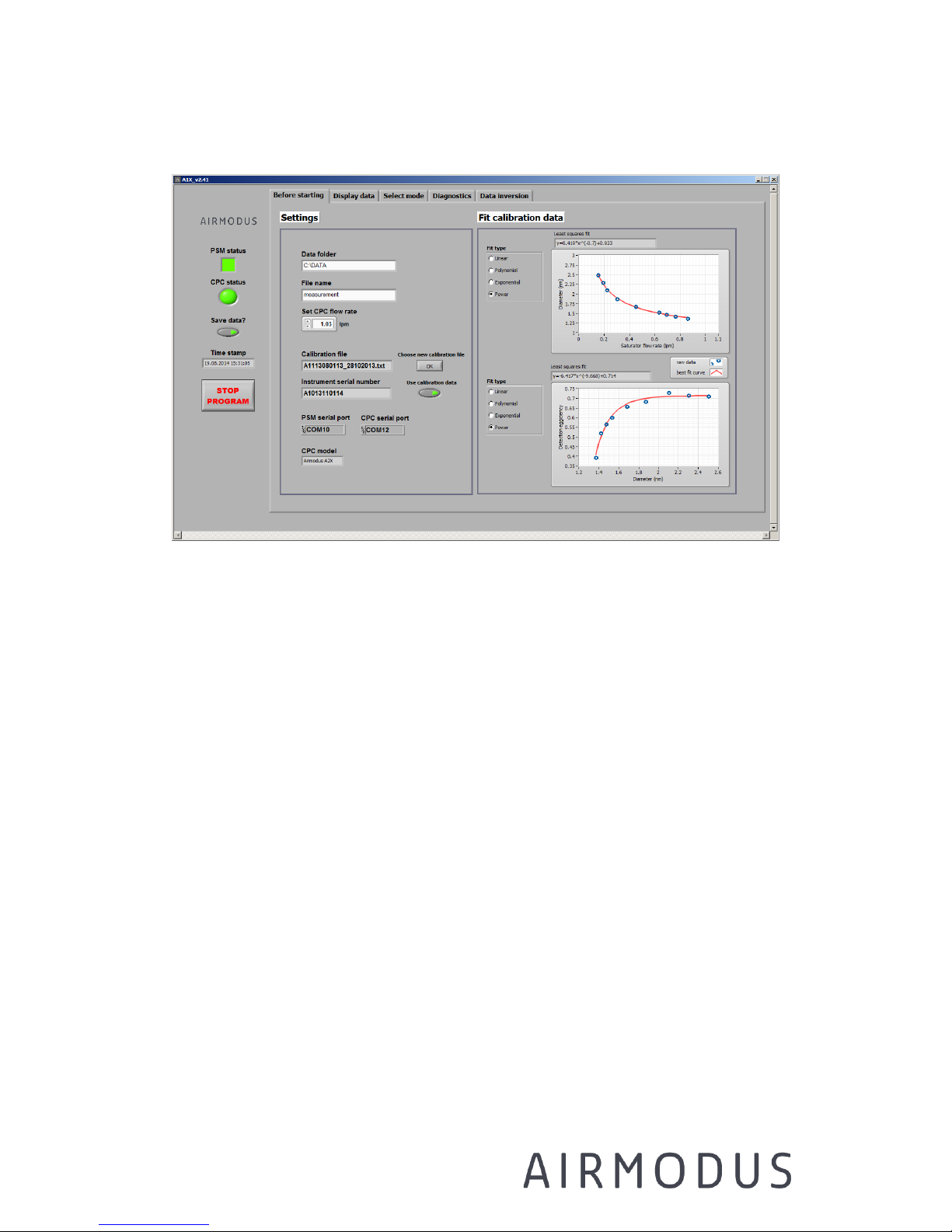
Figure 6-3 Before starting tab
Go to Before starting tab (Figure 6-3) and check that the CPC and PSM
COM ports are the right ones. Check that the calibration file name is
correct. For choosing a new calibration file, click Choose new calibration
file. Check that there is data displayed in the graphs on the right-hand
side. Choose the best fittings to the measured calibration data. These will
be used for data inversion and estimating the cut-off diameter. NOTE:
ONLY WHEN USED WITH AIRMODUS CPC!
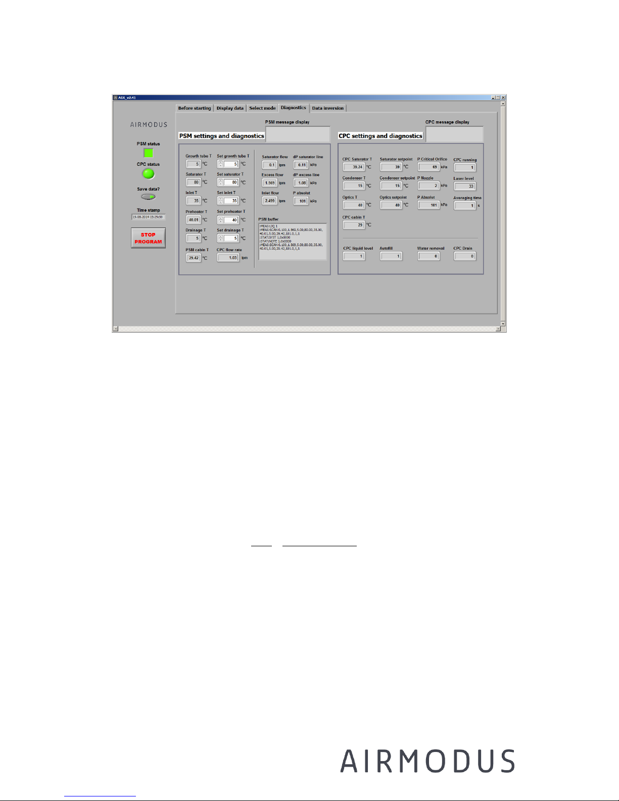
Check that the temperature and flow rate values are updated regularly in
the Diagnostics tab (Figure 6-4)
Page 28
AIRMODUS A11 nCNC USER MANUAL Page 28
Ref. A13TD0015
Version 1.94 Document date: 18.08.2017
© 2017 Airmodus Ltd
Figure 6-4 The Diagnostics tab
Check that the inlet flow rate of the PSM is about 2.5 lpm and CPC 1 lpm
by using a low-pressure drop flow meter. Please note that the PSM uses
mass flow controllers to control the flows and the sample temperature and
pressure will affect the volumetric flow rate measured from the inlet.
The mass flow meters inside the PSM are calibrated to standard conditions
of 20oC (T
cal
) temperature and 101.3 kPa in pressure (P
cal
). If the PSM is
used in temperature T and pressure P, the volumetric flow rate Q will be:
𝑄 =
𝑃𝑐𝑎𝑙
𝑃
×
𝑇 + 273.150𝐾
𝑇𝑐𝑎𝑙 + 273.150𝐾
×𝑄𝑠𝑡𝑑
If you are starting the instrument when it has been dry of DEG, go to the
Select mode tab, put 90 seconds to the Priming time selector, and push
Prime button. This lets DEG to flow into the saturator. The priming will
stop by itself after the selected time. After priming let the instrument
stabilize for at least 1h.
Page 29

AIRMODUS A11 nCNC USER MANUAL Page 29
Ref. A13TD0015
Version 1.94 Document date: 18.08.2017
© 2017 Airmodus Ltd
Wait until all the temperatures have reached their correct settings and the
status is green (Figure 6-4)
If there is a problem in the data communication with the CPC or the PSM,
the status light will turn red and an explanation or a received device error
with a possible tip for solving the problem is displayed in the message
field on the diagnostics tab. If the software is able to open the
communication with the chosen COM-ports but doesn't receive any data, a
message "CPC/PSM communication error" is shown. With any data
communication problem it's usually good to check that the cables are
connected to the right COM-ports and restart the software.
NOTE: If the A1X software is closed and reopened, you have to start the
desired measurement mode again in order to start the online data
inversion and inverted data saving.
Page 30

AIRMODUS A11 nCNC USER MANUAL Page 30
Ref. A13TD0015
Version 1.94 Document date: 18.08.2017
© 2017 Airmodus Ltd
7 Operation and Maintenance
NOTE: We recommend the use of an uninterruptible power supply for any
measurement systems.
7.1 Working with the nCNC
• Different cut-off sizes can be obtained by selecting different
saturator flow rates (mixing ratios). Other flows will be adjusted
automatically so that the inlet flow rate should stay constant. After
changing flow rates the Status light will turn red until the flows
have stabilized. See chapter 7.4 for selecting the correct operation
mode.
• PSM temperature set points can be adjusted in the Diagnostics tab
(Figure 6-4, on page 28) on the software. Status light will stay red
until the new temperatures have been achieved, let the instrument
stabilize after changing temperature settings.
NOTE: Calibration will be void if the operating temperatures are
changed! Inverted data will not be valid.
• It’s a good practise to measure the inlet flows of both of the
instruments and the zero background concentration regularly (e.g.
once per week). See chapter 7.8 on page 52 for verifying the flows.
The background can be measured by inserting a HEPA filter in front
of the inlet.
• A small amount of DEG can get in the tube connecting the PSM to
the CPC with the outlet flow. For preventing the DEG of entering the
CPC, have the drip bottle connected to the outlet of the PSM and
Page 31
AIRMODUS A11 nCNC USER MANUAL Page 31
Ref. A13TD0015
Version 1.94 Document date: 18.08.2017
© 2017 Airmodus Ltd
place the CPC on a higher level than the PSM. Clean the tube
connecting the PSM to the CPC regularly, and empty the drip bottle
before it gets full. Both the tube and the drip bottle can be washed
with pure water. Dry the tube and drip bottle before reconnecting
them to the PSM and CPC. If you suspect the PSM to be flooded,
immediately disconnect it from your system.
NOTE: the diffusional losses of particles smaller than 4 nm can be
substantial. Therefore use as short inlet tube as possible before the PSM,
or use make-up flow.
Warning: If pressurized air is connected while the vacuum is
disconnected from the PSM, and the PSM is on, there may be some DEG
vapour coming out of the outlet or inlet of the instrument (see material
safety data sheet of diethylene glycol).
7.2 CPC Operation and maintenance
7.2.1 CPC Display and settings
The touch screen of the CPC displays one of five different screens. One
can change the currently shown screen from the bottom of the touch
screen.
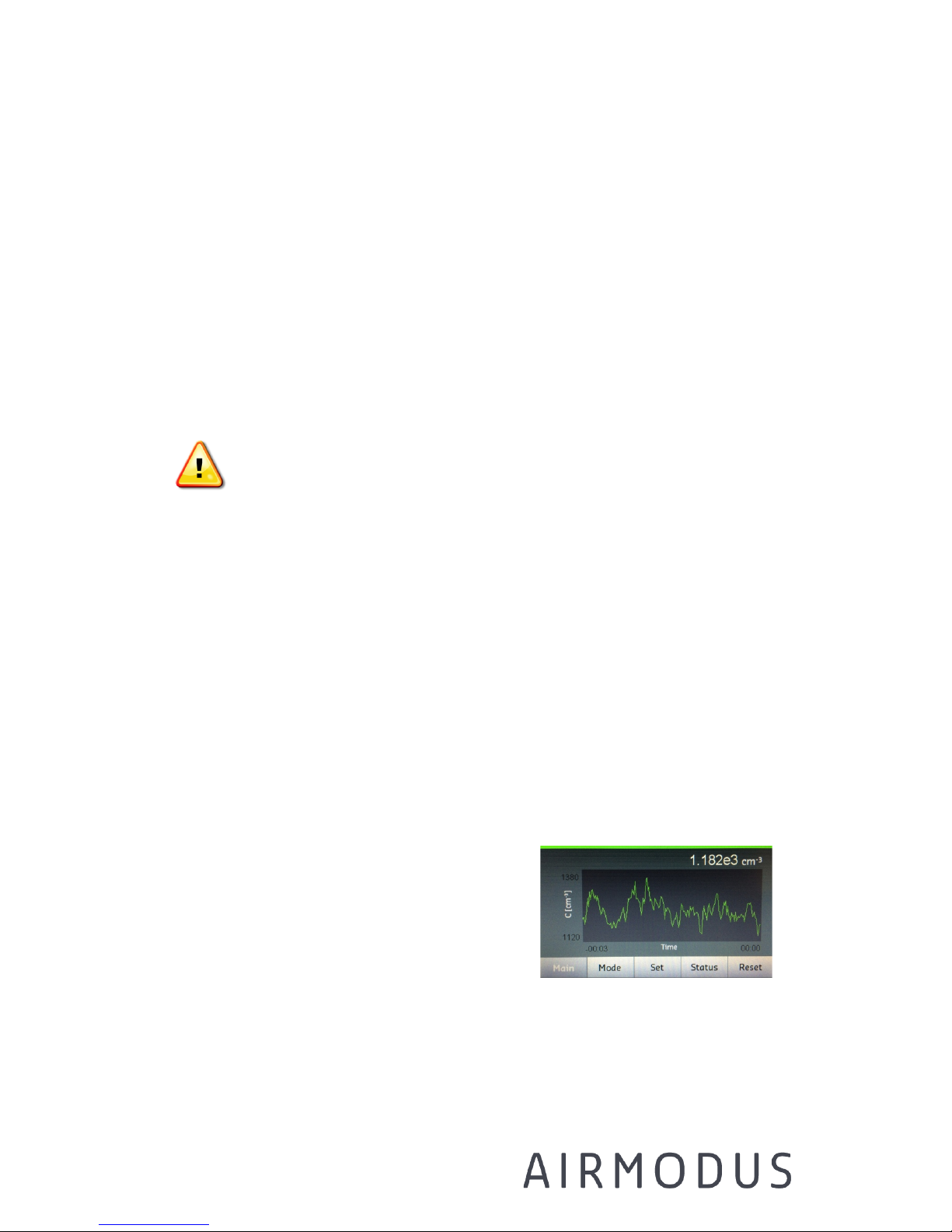
Main screen
On the main screen, the measured
concentration is shown as number
concentration per cubic centimeter, and the
data is shown as a time series (30 previous
data points). The averaging time used for
displaying the data should NOT be changed when using the A20 CPC in
the A11 system (the averaging time should always be 1 s). The y-axis
Page 32
AIRMODUS A11 nCNC USER MANUAL Page 32
Ref. A13TD0015
Version 1.94 Document date: 18.08.2017
© 2017 Airmodus Ltd
scale can be changed between linear or logarithmic scale from MODE
screen.
The concentration value changes to red if the status of the instrument is
not ok. An arrow symbol is displayed in front of the concentration value, if
the concentration is higher than 30 000/cc and the Total Scattering Mode
correction factor is applied.
Total Scattering Mode Correction: At high particle concentration a CPC
can’t count all the particles due to coincidence. Commonly 10% of
coincidence is considered acceptable. The amount of coincidence in single
particle counting mode is defined by the pulse width of the optical counter
signal; narrow pulse width allows higher concentrations to be detected.
With A20 the 10% limit is at 30 000#/cc. After this the counted
concentration data is corrected with a parameterization that is a function
of the total scattering signal. This sophisticated method assures a smooth
transition from single counting mode to total scattering mode.
Note: The concentration reading from the CPC Main Screen is not the
same as the concentration shown in the A1X software’s Display Data
screen due to dilution of the sample inside the PSM (see chapter 7.7).
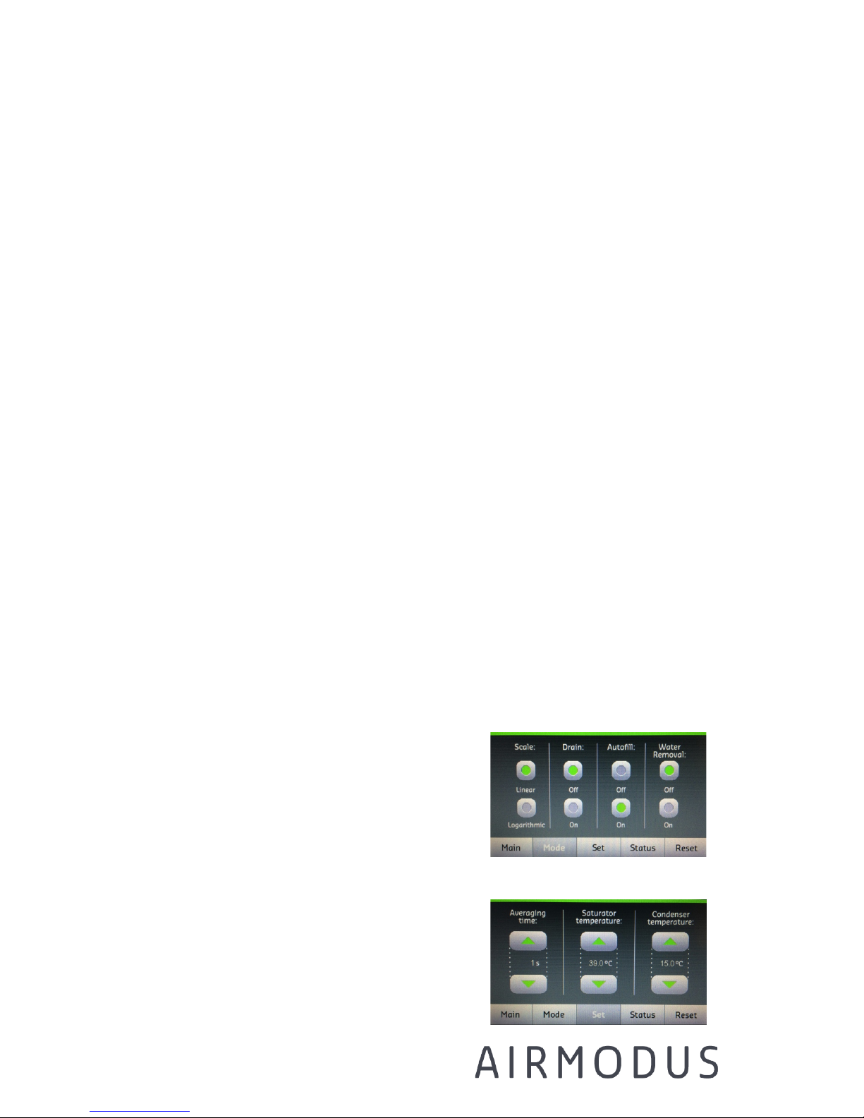
Mode screen
On the mode screen one can change the
fill/drain options and change the time
series scale to logarithmic or linear.
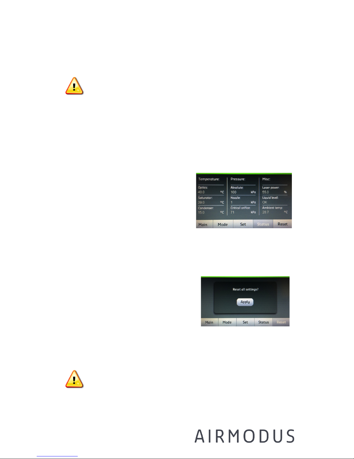
Set screen
On the SET screen one can change the
saturator and condenser temperature, and
the data averaging time. The values can be
Page 33
AIRMODUS A11 nCNC USER MANUAL Page 33
Ref. A13TD0015
Version 1.94 Document date: 18.08.2017
© 2017 Airmodus Ltd
changed by pressing the upward/downward arrows.
Note: changing the temperature settings will affect the cut-off size
and performance of the instrument. The calibration and given cut-off size
are valid only for the temperature settings indicated in the calibration
certificate.
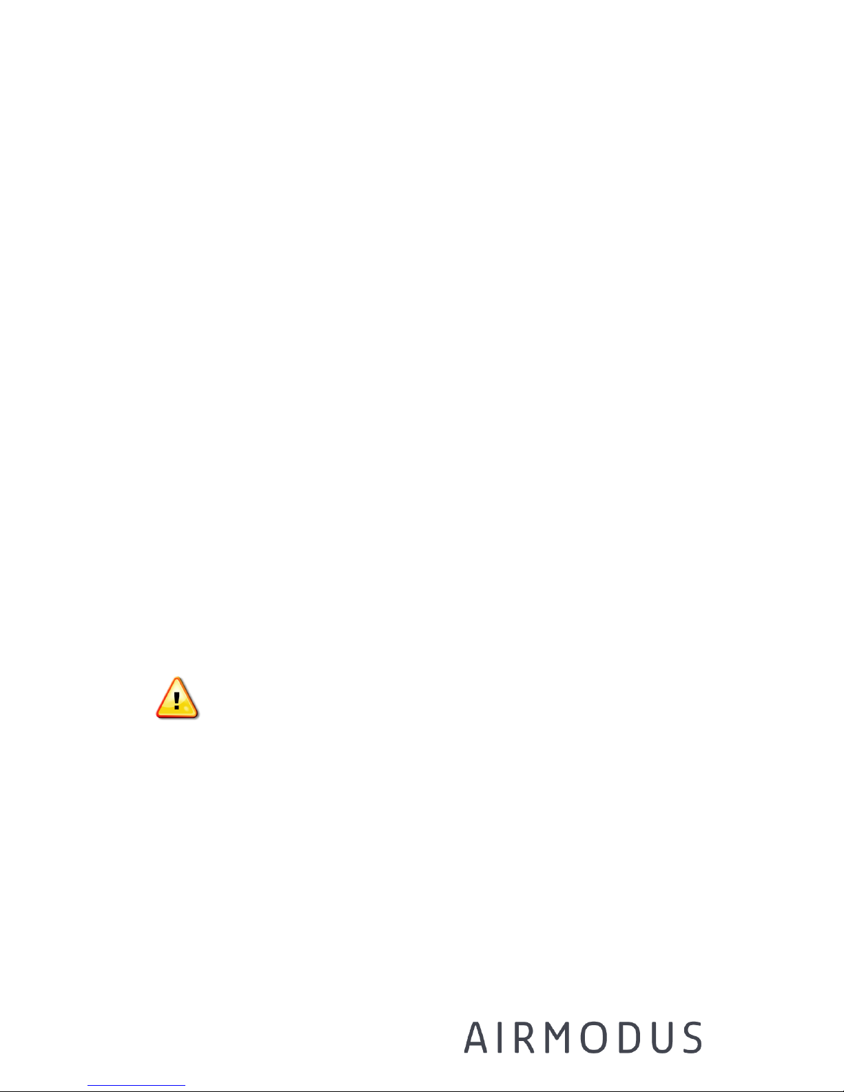
Status screen
The instrument temperatures, pressures,
liquid level and other parameters are
shown in the status screen. If any of the
values are out-of-range, the status light
will be red and the value in question
turns red.
Reset
The default settings of the instrument can
be retrieved from the reset screen.
7.2.2 Filling, draining and drying butanol of the CPC
N-butanol is needed as working fluid for the A20.
Warning: Butanol is a flammable solvent and can be toxic when
inhaled (see material safety data sheet of n-butanol).
Page 34
AIRMODUS A11 nCNC USER MANUAL Page 34
Ref. A13TD0015
Version 1.94 Document date: 18.08.2017
© 2017 Airmodus Ltd
Butanol is filled automatically, when AUTOFILL option is on. The fill bottle
should be attached to the FILL-connector on the front panel. If the
instrument is totally dry, it can take up to 30 min until the butanol
reservoir is full and the instrument measures correctly. Make sure that
there is a hole in the cap of the fill bottle, or that the cap is slightly open,
to ensure pressure stabilization inside the bottle.
When the liquid level in the instrument is too low, the indicator on the
STATUS screen displays LOW. When the level is correct, OK is displayed.
For draining, attach a drain bottle to the DRAIN connector in the front
panel, and press DRAIN from set-screen. Extra liquid should flow into the
drain bottle. Usually a bit of under pressure in the drain bottle is needed
to start the draining. Remember to put AUTOFILL back on if you continue
measurements after draining.
When the sample air is humid, we recommend draining the instrument
with constant intervals, such as once per week, because water will
condense inside the instrument and eventually replaces the n-butanol
inside the saturator.
Note: Always drain the instrument before moving it and dry the
instrument before transport. It is recommended to dry the instrument also
before storage.
DRYING before transportation or storage:
Disconnect the CPC from the PSM. Disconnect the fill bottle and drain the
CPC. Let the instrument run dry in drain mode for at least 24 hours.
Check that the concentration reading of the CPC is zero after the drying
period, and that there is no more butanol coming out of the CPC when
draining.
Page 35
AIRMODUS A11 nCNC USER MANUAL Page 35
Ref. A13TD0015
Version 1.94 Document date: 18.08.2017
© 2017 Airmodus Ltd
Connecting an empty fill bottle to the fill connector and having the autofill
on for a minute will help the drying by letting the n-butanol inside the fill
line quicker to the drain. The drying can also be helped by a bit of under
pressure in the drain bottle a few times during the drying period, as when
starting the draining.
Warning: Do not tilt the instrument when there is butanol inside,
to avoid flooding it.
7.3 Filling, priming, draining and drying DEG of the PSM
7.3.1 Filling
• The PSM uses diethylene glycol (DEG, (HOCH2CH2)2O; 99% purity
is recommended) as working fluid.
• When the fill bottle is attached to the FILL connector in the front
panel, the PSM will take in the DEG automatically.
• Make sure that there is a hole in the cap of the fill bottle, or that
the cap is slightly open, to ensure pressure stabilization inside the
bottle.
• Operate the instrument with the DEG fill bottle ALWAYS connected.
• Refill the fill bottle BEFORE the level reaches the bottom connection
to avoid getting air bubbles in the PSM saturator.
7.3.2 Priming
• If you are starting the instrument when it has been dry of DEG, e.g.
after transport, the instrument needs to be primed to assure proper
functioning. Pressing prime button opens a valve, which lets DEG
flow into the saturator.
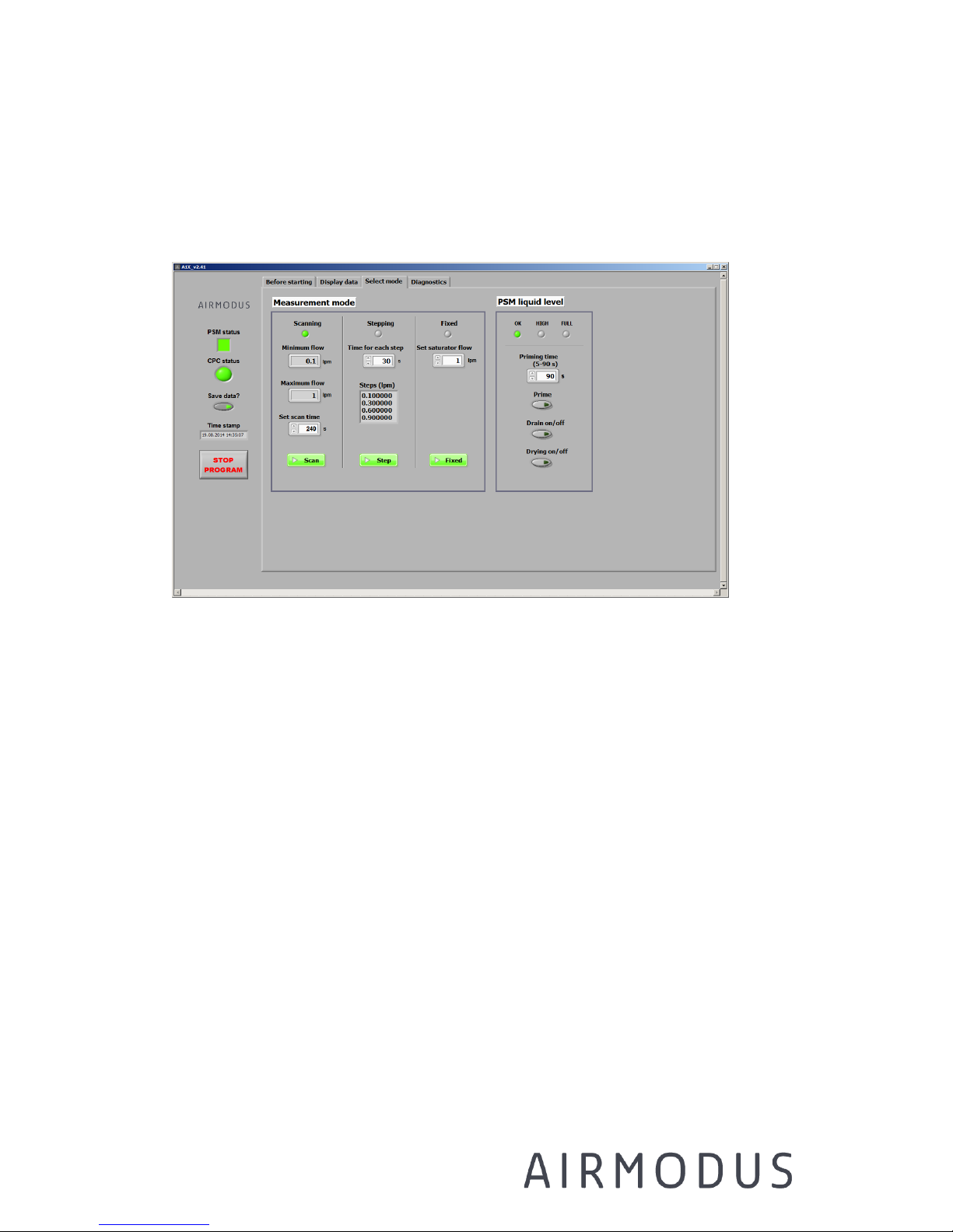
• Go to the Select mode tab (see Figure 7-1), put 90 s to the Priming
time selector, and push Prime button. The priming will stop by itself
Page 36

AIRMODUS A11 nCNC USER MANUAL Page 36
Ref. A13TD0015
Version 1.94 Document date: 18.08.2017
© 2017 Airmodus Ltd
after the selected time. To make sure the saturator is full of DEG,
the priming function can be repeated once.
While priming the fill bottle needs to be connected and full. The priming
will temporarily lower the saturator temperature. After priming let the
instrument stabilize for at least 1h.
7.3.3 Draining and drying
Warning: DEG should be disposed according to local regulations.
Use appropriate measures to ensure safe disposal.
• Used DEG is collected to an internal reservoir, which needs to be
drained by the user. The draining frequency depends on both the
DEG consumption and relative humidity of the sample. It is good
practice to drain the PSM at least every time the fill bottle is refilled, in order not to overfill the internal drain reservoir.
• During continuous measurements, it is recommended to drain and
prime the instrument weekly.
• The status LED will turn yellow and the “High” is lit on the Drain
level panel when the internal drain reservoir starts to be full and
needs to be drained. The status LED turns red and PSM goes to
stand-by mode when the internal drain reservoir is full.
NOTE: the PSM will not recover from the stand-by mode without a
user intervention: drain the PSM until the drain led turns green
again, stop the measurement software, switch the PSM off and on
from the power switch from the back panel. Start the measurement
software again.
Page 37
AIRMODUS A11 nCNC USER MANUAL Page 37
Ref. A13TD0015
Version 1.94 Document date: 18.08.2017
© 2017 Airmodus Ltd
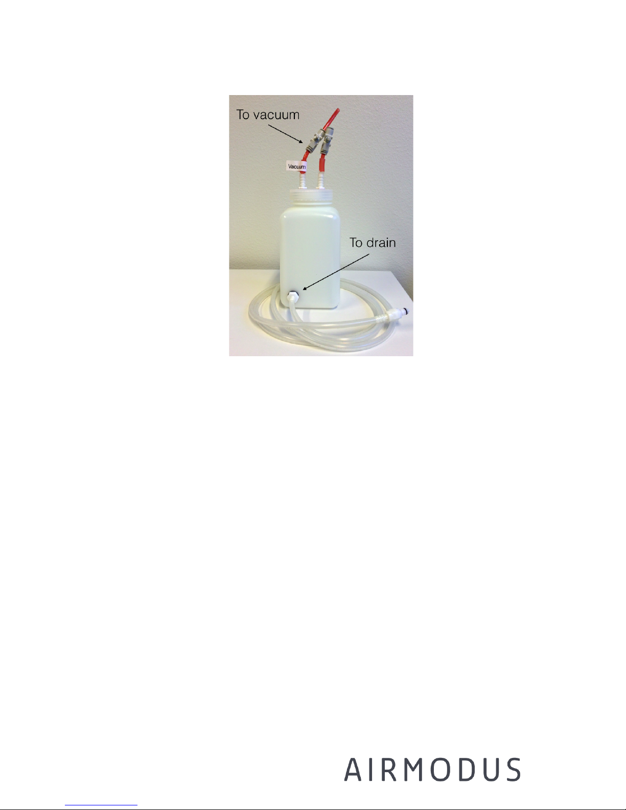
• DRAINING: attach the drain bottle to the DRAIN connector.
• Press the button “DRAIN” on the Select mode tab of the PSM_A1X
software
• Connect external vacuum or a pump to the connector on the cap of
the drain bottle. DEG should start to flow out from the drain to the
drain bottle. The needle valves connected to the cap can be
adjusted to set sufficient under pressure to the bottle to start the
flow (pressure depends on the vacuum pump used). NOTE: Make
sure that the drain bottle will not squeeze!
• Stop the draining by pressing the DRAIN button again
DRYING before transportation or storage:
!!! Always dry the instrument before transport !!!
Dry the instrument also before storage.
Remove the fill bottle. Disconnect the CPC, compressed air and
vacuum from the PSM. Attach the drain bottle as explained above,
Page 38
AIRMODUS A11 nCNC USER MANUAL Page 38
Ref. A13TD0015
Version 1.94 Document date: 18.08.2017
© 2017 Airmodus Ltd
and connect the vacuum to the drain bottle. Press the button DRY
on the A1X software. Then clog the inlet and outlet of the PSM. Let
the instrument dry for at least 24h.
Figure 7-1 The “Select mode” tab, with the liquid operation
commands on the right-hand side
7.4 Selecting operation mode
The Airmodus A11 can operate in three modes:
1. FIXED FLOW – the instrument has a constant selectable saturator
flow rate (cut-off size)
2. STEPPING MODE – the instrument steps between 2-4 user-
selectable saturator flow rates (cut-off sizes)
3. SCANNING MODE – the saturator flow rate is changed continuously,
giving an activation spectrum of the particles
The mode is selected from the Select mode tab on the software, and the
corresponding led is lit. Notice, when you first time start the
measurement, you need to make sure from the display that the correct
mode is on.
Page 39
AIRMODUS A11 nCNC USER MANUAL Page 39
Ref. A13TD0015
Version 1.94 Document date: 18.08.2017
© 2017 Airmodus Ltd
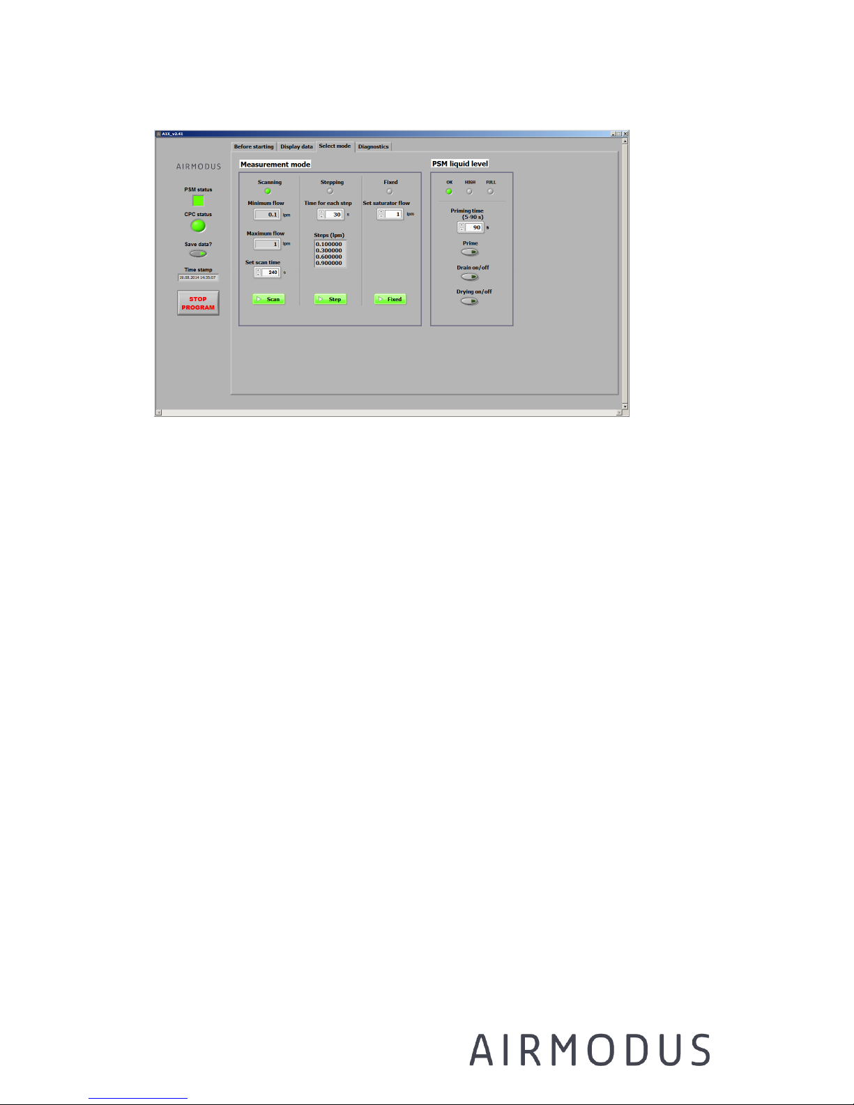
Figure 7-2 The tab to select different modes in the A1X software.
The mode is started when the green button Scan/Step/Fixed is
pushed.
7.4.1 Fixed cut-off
FIXED FLOW operation:
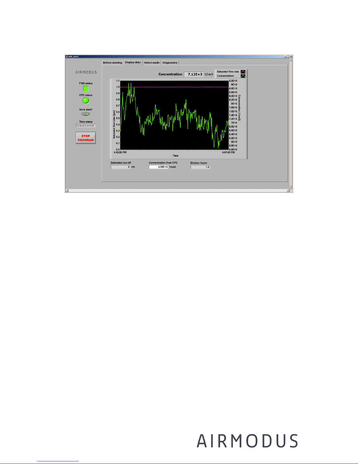
The user can choose a constant flow rate in the range from 0.1 lpm to 1.3
lpm. In the fixed mode the saturator flow rate is changed from the Select
mode tab.
Page 40
AIRMODUS A11 nCNC USER MANUAL Page 40
Ref. A13TD0015
Version 1.94 Document date: 18.08.2017
© 2017 Airmodus Ltd
Figure 7-3 PSM in fixed mode.
7.4.2 Stepping mode
STEPPING MODE operation:
In the stepping mode the saturator flow is automatically changed after the
selected step time has passed.
The measurement time for each step is user selectable, but we
recommend that the step time should be at least 30 s, as it takes time
until the flow rate and concentration stabilizes after a step change. A
yellow status light is displayed when the step is changing. When using
Airmodus CPC, the software saves .step file that gives the median
concentration of one step discarding the first 10 s of the step. When using
other CPCs the user should take care that he / she doesn’t use the data
just after the step change (from the .DAT file). The proper waiting time
depends on the difference between the two successive steps, and the
response time of the system (see Chapter 7.10 on page 53).
Page 41
AIRMODUS A11 nCNC USER MANUAL Page 41
Ref. A13TD0015
Version 1.94 Document date: 18.08.2017
© 2017 Airmodus Ltd
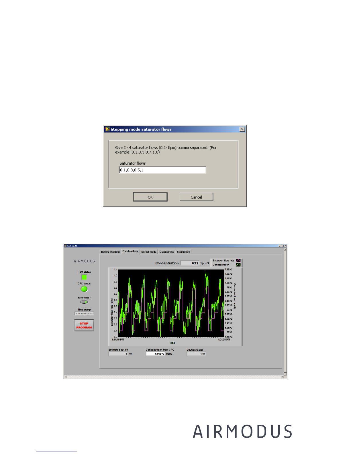
When the Step mode start button is pressed, a pop-up window is
displayed, to which the user needs to write the selected saturator flow
rates (for example: 0.1,0.2,0.5,1.3). The minimum number of steps is 2
and maximum number of steps is 4. The selected steps are displayed in
the screen. For changing the selected steps, press Step mode button
again.
Figure 7-4 Pop-up window for selecting the used flow rates in the
step mode.
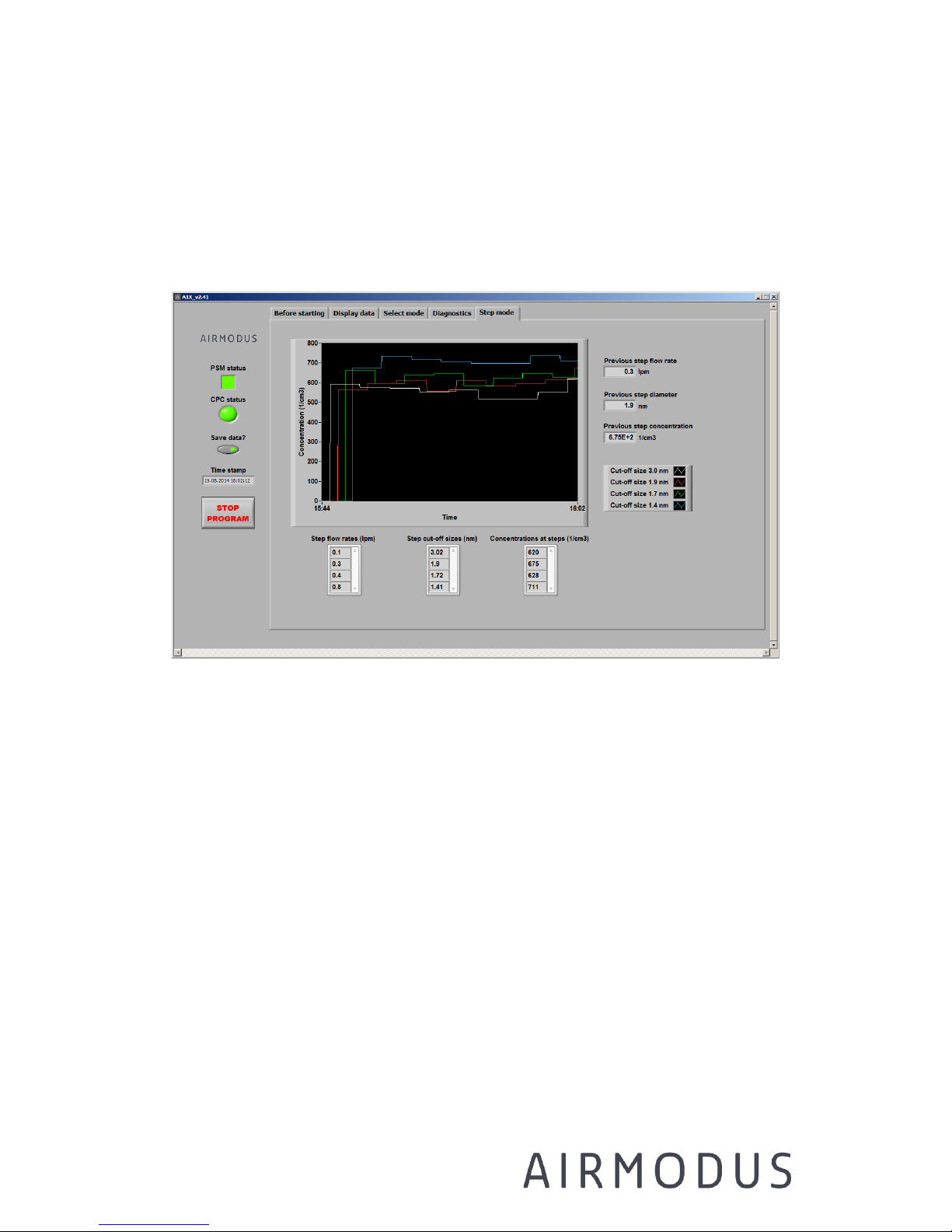
Figure 7-5 PSM in stepping mode
Page 42
AIRMODUS A11 nCNC USER MANUAL Page 42
Ref. A13TD0015
Version 1.94 Document date: 18.08.2017
© 2017 Airmodus Ltd
When the PSM is in the stepping mode an additional tab (Step mode,
Figure 7-6) is displayed, where the average concentration calculated for
each step is shown (ONLY WHEN USED WITH AIRMODUS CPC). The
median concentration measured with each corresponding cut-off size is
displayed with separate lines.
Figure 7-6 Inverted step data
7.4.3 Scanning
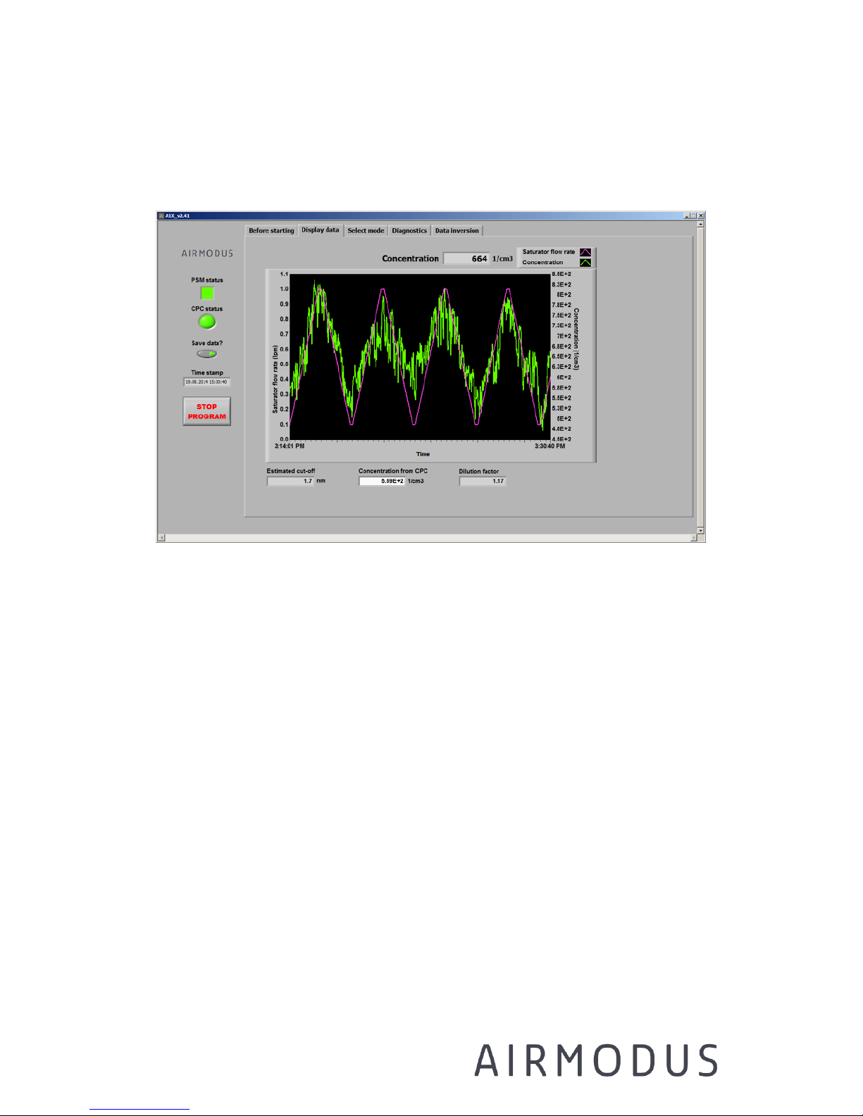
SCANNING MODE operation:
In scanning mode the saturator flow rate is automatically and
continuously changed.
Scanning mode can be selected from the Select mode tab. After pressing
the SCAN mode start button, the saturator flow rate starts increasing with
100 steps between the minimum and maximum flow. An upward ramp is
automatically followed by a downward ramp and vice versa. The minimum
and maximum flow rates are 0.1-1.3 lpm, and time for each step is 1s.
The total time for a complete scan (up and down) is 240 s (4 min). For
starting the SCAN-mode measurement: press the SCAN button on the
Page 43
AIRMODUS A11 nCNC USER MANUAL Page 43
Ref. A13TD0015
Version 1.94 Document date: 18.08.2017
© 2017 Airmodus Ltd
Select mode tab (a green light should appear on the button). The scan
mode can be stopped by pressing the FIXED or STEP button on the Select
mode tab.
Figure 7-7 PSM in scanning mode
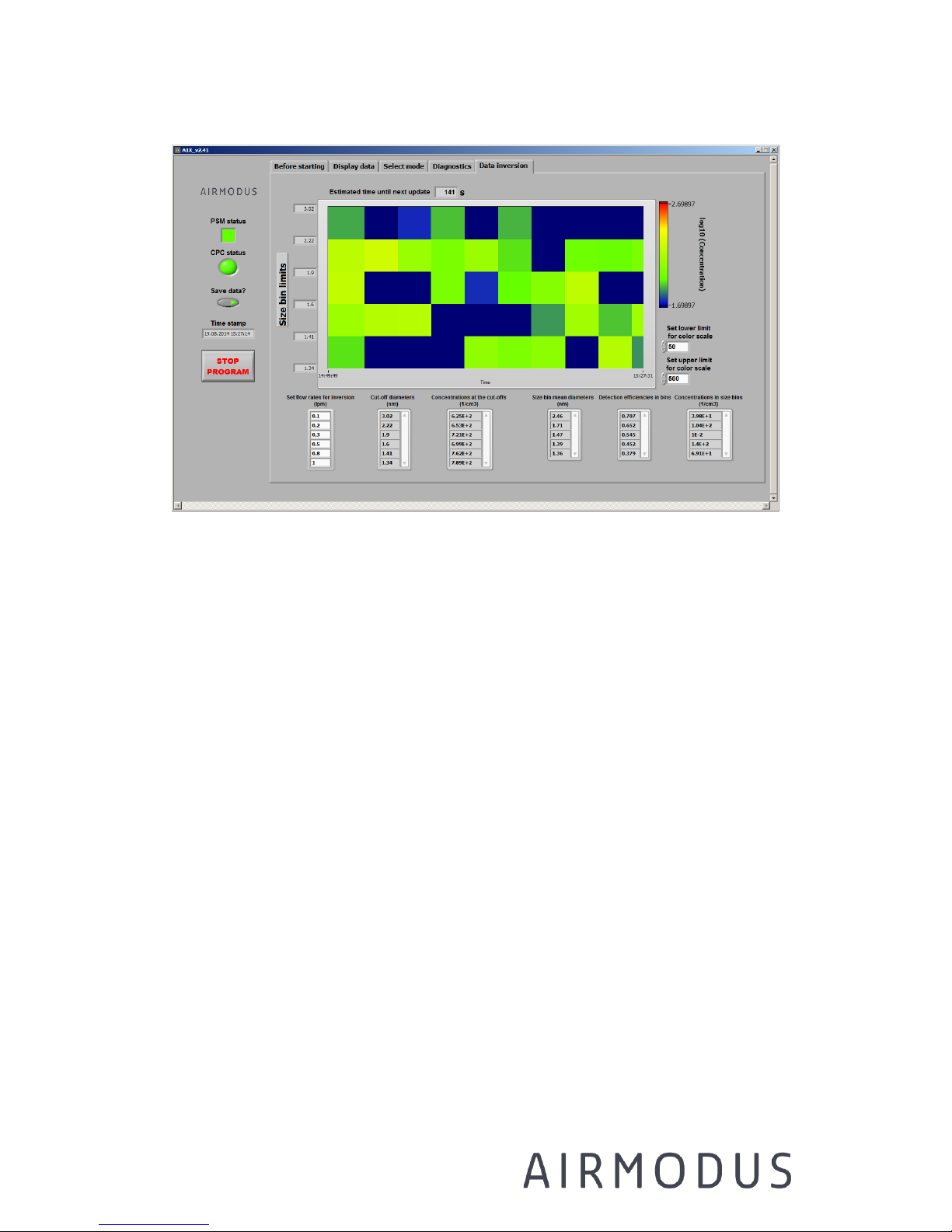
In scan mode, and additional tab (Data inversion, Figure 7-7) is shown
(ONLY WHEN USED WITH AIRMODUS CPC). Here the user can select the
saturator flow rates vector (set flow rates for inversion), which determines
the limits of the size bins. The software calculates the number of particles
which were activated between these flow rates, corrects the number of
particles with the detection efficiency at the mean size of that size bin,
and displays the resulting concentration in each size bin as a colour. The
colour scale can be adjusted from the lower right side of the figure.
Page 44
AIRMODUS A11 nCNC USER MANUAL Page 44
Ref. A13TD0015
Version 1.94 Document date: 18.08.2017
© 2017 Airmodus Ltd
Figure 7-8. Inverted scan data
7.5 Operation environment and safety
The nCNC is intended for measuring fine airborne particles (diameter 1-
1000 nm) in the concentration range 0-1e5/cc. It is recommended to use
the nCNC in single particle counting mode, i.e. concentration range 0-
3e4/cc. The sample air should not contain coarse material (e.g. insects,
sand, dust, flour, pollen), which can block the instrument. If necessary, an
impactor or a suitable mesh-filter should be used in front of the inlet.
The nCNC should be operated at close to normal room temperature (15-
30 °C)
Do not measure hazardous or flammable gases (e.g. H2).
Do not block the fans of the instrument and ensure proper ventilation for
not overheating it.
Page 45

AIRMODUS A11 nCNC USER MANUAL Page 45
Ref. A13TD0015
Version 1.94 Document date: 18.08.2017
© 2017 Airmodus Ltd
The PSM and the CPC should be placed onto an even surface. Do not tilt
the instruments to avoid flooding.
Do not block the inlet, when the nCNC is measuring and/or connected to
the vacuum line.
Drain the instrument properly before moving or transport. Do not put any
other liquid than DEG or butanol inside the PSM and CPC, respectively.
Do not remove the cover of the instrument during measurement or when
power is on and do not modify or replace any parts of the instrument.
All service and maintenance should be performed by qualified technician.
Do not replace, remove or modify any parts of the nCNC.
7.6 Communication
Airmodus A10 PSM and the A20 CPC have a RS-232 serial port and a
USB2.0 port for communicating with a standard PC. The user can decide
which connection is more suitable for their purpose. We recommend
avoiding serial to USB converters in case the PC or laptop is not equipped
with an RS-232 port, but to use the USB instead.
A1X software takes care of the communication between the PC and the
Airmodus A11.
For RS-232 communication the following specifications apply:
Baud rate: 115200
Bits: 8
Parity: None
Stop bits: 1
All commands and responses are sent or received as ASCII characters. All
messages are terminated with a <CR>
Page 46

AIRMODUS A11 nCNC USER MANUAL Page 46
Ref. A13TD0015
Version 1.94 Document date: 18.08.2017
© 2017 Airmodus Ltd
For a complete list of the commands, see Appendix 3 and 4.
7.7 Data management and saving data
The A1X software can be used to display and record data from the PSM
and the CPC, change measurement mode and settings, and monitor the
instrument status.
The current saturator flow rate and concentration as a function of time is
displayed on the Display data tab. The screen can be reset by right-
clicking on it and selecting ‘Clear Screen’. An estimation of the current
cut-off size is given at the bottom of the display.
Temperatures, pressures and other flow rates can be seen from the
Diagnostics tab. From there you can also change the temperature settings
of the PSM. Note that the calibration of the instrument is only valid for the
default settings listed in the calibration certificate. All the values are
written in a data file once in a second when ‘Save data’ button is ON
(green light lit). The data folder and file name can be chosen from the
Before starting tab.
The concentration measured by the CPC is corrected for the dilution
caused by mixing the sample with the particle-free saturator air. The
software does this automatically.
𝐶𝑜𝑛𝑐
89:
= 𝐶𝑜𝑛𝑐
;8;
∗ 𝐷𝑖𝑙𝑢𝑡𝑖𝑜𝑛0𝑟𝑎𝑡𝑖𝑜
𝐷𝑖𝑙𝑢𝑡𝑖𝑜𝑛0𝑟𝑎𝑡𝑖𝑜 = 0
𝑄
ABCDE
+ 𝑄
FGEHIGEJI
𝑄
ABCDE
Page 47

AIRMODUS A11 nCNC USER MANUAL Page 47
Ref. A13TD0015
Version 1.94 Document date: 18.08.2017
© 2017 Airmodus Ltd
The concentration is not corrected for losses, which might be substantial
for the smallest particles.
NOTE: With other than Airmodus CPCs the corrected concentration is
acquired from the CPC with the RD command that only gives the CPCs
concentration reading from the display. So when you measure the inlet
flow rate of the CPC and enter the value to the A1X software please note
that it is used to correct for the internal dilution of the PSM but with other
than Airmodus CPCs it is not used to correct for the CPCs internal
counting. For example, if the real measured inlet flow rate of a TSI CPC is
1.05 lpm, and the CPC itself believes it is 1.0 lpm the CPC gives 5% too
high concentration value. For Airmodus CPC this is corrected automatically
because the A1X software sends the measured value for both PSM and the
Airmodus CPC.
The A1X software checks the PSM and CPC status, which tells you when
the instrument operates correctly. The status led in the software window
is green when all parameters are inside accepted range. The status turns
yellow, when the instrument gives a warning about warming up state,
draining, drying, or changing the saturator flow in the step mode. The
user does not need to do anything due to a warning, but the data might
not be valid. The warning is displayed as text in the Message display on
the Diagnostics tab. If some of the parameters, e.g. temperatures or flows
are outside the accepted range, the status led turns red and an error
message is displayed. If the error persists, you need to check the
operation of the instrument.
The CPC status led shows the status value of the CPC. For Airmodus CPC
the software will also give the diagnostics and setting values. For TSI
CPCs is not supported.
Page 48

AIRMODUS A11 nCNC USER MANUAL Page 48
Ref. A13TD0015
Version 1.94 Document date: 18.08.2017
© 2017 Airmodus Ltd
NOTE: Please don’t try to read or write the data file with any other
software while the A1X software is saving data.
7.7.1 Raw data file
The data is saved every second to a file named identifier_yymmdd.dat to
the user selected folder. The different values are separated by a comma.
Row 1 - header:
Instrument serial nr or name from flash, name of calibration file used
Next rows – data for Airmodus CPCs: comma separated values in
the following order:
Column'1'
time (dd.mm.yyyy HH:MM:SS)
Column'2'
concentration from PSM (1/cm3) (corrected for dilution)
Column'3'
cut-off diameter (nm) based on the given calibration data
Column'4'
saturator flow rate (lpm)
Column'5'
excess flow rate (lpm)
Column'6'
PSM saturator T (C)
Column'7'
growth tube T (C)
Column'8'
inlet T (C)
Column'9'
drainage T (C)
Column'10'
preheater T (C)
Column'11'
PSM cabin T (C)
Column'12'
absolute pressure (measured in the inlet of PSM) (kPa)
Column'13'
dP saturator line (kPa)
Column'14'
dP excess line (kPa)
Column'15'
PSM status value (1=ok, 0=not ok)
Column'16'
PSM note value (1=ok, 0=notes)
Column'17'
CPC concentration (1/cm3)
Column'18'
dilution correction factor
Column'19'
CPC system running (1=ok)
Column'20'
CPC autofill (1=on, 0=not on)
Column'21'
CPC drain (1=on, 0=not on)
Column'22'
CPC water removal (1=on, 0=not on)
Column'23'
CPC saturator T (C)
Column'24'
CPC saturator T setpoint (C)
Column'25'
CPC condenser T (C)
Column'26'
CPC condenser T setpoint (C)
Page 49

AIRMODUS A11 nCNC USER MANUAL Page 49
Ref. A13TD0015
Version 1.94 Document date: 18.08.2017
© 2017 Airmodus Ltd
Column'27'
CPC optics T (C)
Column'28'
CPC optics T setpoint (C)
Column'29'
CPC cabin T (C)
Column'30'
CPC inlet flow rate (lpm)
Column'31'
CPC P critical orifice (kPa)
Column'32'
CPC P extra (not used) (kPa)
Column'33'
CPC P nozzle (kPa)
Column'34'
CPC P absolute (measured in the inlet of CPC) (kPa)
Column'35'
CPC liquid level (1=ok, 0=not ok, 2=OVERFILL)
Column'36'
CPC laser level (%)
Column'37'
CPC averaging time (s)
Column'38'
OPC compare voltage (mV)
Column'39'
OPC Pulses (number of particle counts during the CPC
averaging time)
Column'40'
OPC Pulse duration (accumulated dead time during the CPC
averaging time) (us)
Column'41'
OPC DC compensation state (1=on, 0=not on)
Column'42'
OPC voltage level (used in DC compensation to describe the
total scattering)
Column'43'
CPC nr of errors (0=ok)
Column'44'
CPC Self-test Error(s) (Hexadecimal number)
Column'45'
CPC System status Error(s) (Hexadecimal number)
Column'46'
PSM Note(s) (Hexadecimal number)
Column'47'
PSM System status Error(s) (Hexadecimal number)
Next rows – data for TSI CPCs: comma separated values in the
following order:
Column'1'
time (dd.mm.yyyy HH:MM:SS)
Column'2'
concentration from PSM (1/cm3) (corrected for dilution)
Column'3'
cut-off diameter (nm) based on the given calibration data
Column'4'
saturator flow rate (lpm)
Column'5'
excess flow rate (lpm)
Column'6'
PSM saturator T (C)
Column'7'
growth tube T (C)
Column'8'
inlet T (C)
Column'9'
drainage T (C)
Column'10'
preheater T (C)
Column'11'
PSM cabin T (C)
Column'12'
absolute pressure (measured in the inlet of PSM) (kPa)
Column'13'
dP saturator line (kPa)
Column'14'
dP excess line (kPa)
Column'15'
PSM status value (1=ok, 0=not ok)
Page 50

AIRMODUS A11 nCNC USER MANUAL Page 50
Ref. A13TD0015
Version 1.94 Document date: 18.08.2017
© 2017 Airmodus Ltd
Column'16'
PSM note value (1=ok, 0=notes)
Column'17'
CPC concentration (1/cm3)
Column'18'
dilution correction factor
Column'19'
CPC system running (1=ok)
Column'20'
CPC inlet flow rate (lpm)
Column'21'
“Not Airmodus CPC”
Column'22'
PSM Note(s) (Hexadecimal number)
Column'23'
PSM System status Error(s) (Hexadecimal number)
Example:
#A11, A1113080113,A1113080113_28102013.txt
30.10.2013
17:44:14,1216.963411,1.392871,0.831000,2.334000,81.000000,5.00000
0,35.000000,5.000000,40.000000,28.670000,101.300000,-
0.900000,1.200000,1.000000,1.000000,898.651794,1.339193,1.000000,
1.000000,0.000000,0.000000,39.010000,39.000000,15.000000,15.0000
00,40.010000,40.000000,25.590000,1.000000,76.000000,1.000000,2.00
0000,100.000000,1.000000,79.000000,1.000000,250.000000,14410.000
000,37894.000000,0.000000,0.007977,0.000000,0x00000000,0x0000,0x
0000,0x0000
#A11,A1013110114,A1113080113_28102013.txt
18.08.2014
00:00:00,617.400000,0.000000,1.000000,1.991000,80.000000,5.000000
,35.000000,5.000000,40.000000,31.050000,101.230000,0.060000,0.660
000,1.000000,1.000000,441.000000,1.400000,1.000000,1.509000,Not
Airmodus CPC,0x0000,0x0000
Page 51

AIRMODUS A11 nCNC USER MANUAL Page 51
Ref. A13TD0015
Version 1.94 Document date: 18.08.2017
© 2017 Airmodus Ltd
7.7.2 Inverted scanning data
In scanning mode, the concentration calculated for the size bins are saved
in the data file called identifier_yyyymmdd.scan
Row 1 - header:
#A11, instrument serial number or name from flash, name of calibration
file used
Next rows - data: comma separated values in the following order
1. column: end time of scan (dd.mm.yyyy HH:MM:SS)
2. column: 1. size bin upper size limit (nm)
3. column: 1. size bin lower size limit (nm)
4. column: 1. size bin concentration between size limits (1/cm3)
5. column: 2. size bin upper size limit (nm)
6. column: 2. size bin lower size limit (nm)
7. column: 2. size bin concentration between size limits (1/cm3)
...
Nth column: PSM status (1=ok, 0=not ok)
Total number of columns depends on the amount of size bins that the user
has selected on the Scan tab.
Example:
#A11,P,A1120130101_15102013.txt
24.10.2013
14:19:54,2.974961,1.861946,49.746058,1.861946,1.495453,413.022874
,1.495453,1.388907,1126.312226,1.388907,1.351180,2437.007323,1.35
1180,1.320000,2387.462752,1.000000
7.7.3 Inverted step data
Page 52

AIRMODUS A11 nCNC USER MANUAL Page 52
Ref. A13TD0015
Version 1.94 Document date: 18.08.2017
© 2017 Airmodus Ltd
In step mode, the concentrations (total concentration with certain cut-off
size) averaged over each step are saved in the data file called
identifier_yyyymmdd.step
Row 1 - header:
#A11, instrument serial number or name from flash, name of calibration
file used
Next rows - data: comma separated values in the following order
1. column: end time of step (dd.mm.yyyy HH:MM:SS)
2. column: 1. concentration averaged over the step (1/cm3)
3. column: 1. saturator flow rate (lpm)
4. column: 1. cut-off size
5. column: PSM status (1=ok, 0=not ok)
Example:
#A11,A1113080110,A1113080113_28102013.txt
10.12.2013 00:00:20,7406.789896,1.000000,1.342000,1.000000
10.12.2013 00:00:48,7102.055007,0.100000,3.022975,1.000000
10.12.2013 00:01:18,7926.155782,0.300000,1.896261,1.000000
10.12.2013 00:01:50,7594.217514,0.700000,1.460830,1s.000000
7.8 Verifying flows
The inlet flow rate can be measured by using a calibrated low pressure
drop volumetric flow or mass flow meter. It is also important to measure
the flow of the CPC in line with the PSM. Remember to use a HEPA filter
upstream the flow meter in order to prevent contamination of the flow
meter by the DEG droplets exiting the PSM. The inlet flow rate of the PSM
should measure 2.5 lpm at 20 degrees centigrade at 1 atmosphere, and
the CPC 1 lpm. Note that the PSM flows are controlled by mass flow
Page 53

AIRMODUS A11 nCNC USER MANUAL Page 53
Ref. A13TD0015
Version 1.94 Document date: 18.08.2017
© 2017 Airmodus Ltd
controllers and the CPC flow is controlled by a critical orifice. Temperature
of surroundings of the instrument and pressure of the inlet will affect the
flows. The calibration conditions are stated in the calibration certificate of
each instrument.
7.9 Moving and shipping the nCNC
Due to the low vapour pressure of the DEG, the instrument is
recommended to be in Drying mode for at least 24 hours before moving.
See Chapters 7.2.2 and 7.3 for draining instructions.
After drying is completed stop the A1X software. Shut down the PSM and
the CPC. Remove the CPC/PSM connection tube. Disconnect the PSM and
CPC power cords, pressure lines, DEG and Butanol fill and drain bottles
and USB- and other cables.
For shipping both the PSM and the CPC need to be completely dry. During
shipping they should not be exposed to weather or rain, temperatures
below 0oC or above 40oC and relative humidity above 95%. The package
should not be dropped and the packing should be properly cushioned.
You may use for example the original shipping box for protecting the
instruments during transportation. Insert the instrument to the box by
first installing the end cushions around the instrument and then carefully
slide the instrument to the cardboard box.
Transit cases can be purchased separately from Airmodus.
7.10 Efficiency & Response time
The detection efficiency of a CPC is defined as the ratio of the measured
concentration and the true concentration. The detection efficiency of the
nCNC is measured during calibration of the instrument using an
electrometer as the concentration reference.
Page 54

AIRMODUS A11 nCNC USER MANUAL Page 54
Ref. A13TD0015
Version 1.94 Document date: 18.08.2017
© 2017 Airmodus Ltd
The detection efficiency of a CPC is dependent on the size of the particles.
The lowest size when the detection efficiency is still > 50% is called the
cut-off diameter. Near the cut-off size of the instrument, the composition
and electric charge of the particles can also affect their detection
efficiency. For the nCNC system, the detection efficiency is a combination
of the growth efficiency and losses of the PSM and the detection efficiency
of the CPC.
The response time of the instrument is here defined as the time when the
count of the CPC reaches 90% of its maximum in a step concentration
change. The measured response time for nCNC (PSM connected to the
A20 CPC with a 45cm tubing) is 4.8 s.
7.11 Replacement Parts
There are some consumables inside the PSM; these are usually replaced
during maintenance by Airmodus. If you have any questions related to the
consumables, please contact [email protected]
The consumables are e.g.: a fuse, HEPA filters
7.12 Flooding of the Instrument
If the instrument malfunctions and PSM gets flooded with DEG, or the CPC
gets flooded with Butanol, immediately detach the CPC from the PSM,
detach the inlet sampling lines, and switch off the flooded instrument.
Detach the vacuum and compressed air. Contact Airmodus for further
instructions of how to clean the lines inside the instrument.
7.13 Calibration
Exact calibration of the instrument is required for establishing a relation
between the flow mixing ratio (saturator flow rate) and the cut-off
diameter. Airmodus performs calibrations using Nickel Chromium particles
produced with hot wire generator and size selected with a high-resolution
differential mobility analyser (DMA). For each instrument, we verify the
Page 55

AIRMODUS A11 nCNC USER MANUAL Page 55
Ref. A13TD0015
Version 1.94 Document date: 18.08.2017
© 2017 Airmodus Ltd
detection efficiency at the highest saturator flow rate, and measure the
activation curve for several particle sizes. The calibration is strictly valid
only for the same particle type (composition, charge). See the calibration
certificate for details of your instrument.
We recommend returning the instrument to calibration and service once
per year. Depending on the operating conditions and usage, the
instrument may need service more often.
For more information on calibrations, and ordering a calibration service,
contact Airmodus. We also perform calibrations tailored for your specific
needs.
7.14 How to get help / Technical contacts
We recommend returning the instrument for calibration and service once
per year. Depending on the operating conditions and usage, the
instrument may need service more often.
Manufacturer and service address:
Airmodus Oy
Erik Palménin aukio 1
FIN-00560 Helsinki, Finland
Please contact us at:
[email protected]
www.airmodus.com
When your instrument needs maintenance or calibration, contact us at
Airmodus for further instructions (see contact details above).
When the service has been agreed on, send the instruments to us. Dry
the instrument as described in this manual and pack it securely.
Page 56

AIRMODUS A11 nCNC USER MANUAL Page 56
Ref. A13TD0015
Version 1.94 Document date: 18.08.2017
© 2017 Airmodus Ltd
8 Troubleshooting
Problem 1: Status light is red
Solution:
1) If PSM was recently started or flow/temperature settings changed,
wait for the temperatures and flows to stabilize.
2) Check the message display in the Diagnostics tab to see which error
or warning messages the instruments give.
3) If the problem persists contact Airmodus.
Problem 2: Software does not read the concentration from the
CPC, or the concentration reading is zero.
Solution:
1) Check that the CPC is on, working and has enough working fluid.
2) Make sure the CPC is connected to the computer via serial or USB
cable.
3) Make sure the CPC COM port number in the psmconfig file and
software window is correct and that the computer recognizes the
port.
4) Try disconnecting the USB cable and restarting the software.
Sometimes changing the USB port might help.
Problem 3: The concentration doesn’t go close to zero, when a
filter is connected to the sample line.
Solution:
1) A few counts from homogenous nucleation is expected at high
saturator flow rates (0.8-1.3lpm), and this background level
should decrease, when decreasing the saturator flow rate.
2) Make sure that the DEG bottle is connected. If not, connect it and
wait for the instrument to stabilize.
Page 57

AIRMODUS A11 nCNC USER MANUAL Page 57
Ref. A13TD0015
Version 1.94 Document date: 18.08.2017
© 2017 Airmodus Ltd
3) Clean the outlet tube between the PSM and CPC from DEG.
4) Check that all flow rates are reasonable and correct. See problem
4.
5) Contact Airmodus.
Problem 4: The flows do not stabilize or show incorrect readings.
Solution:
1) Make sure pressurized air and external vacuum are connected to
the PSM and are sufficient.
2) Make sure external vacuum is connected to the CPC and is
sufficient.
3) Measure the flow rate between CPC and PSM and make sure it is
correctly entered to the psmconfig file or the A1X software.
4) Measure the inlet flow rate. It should be 2.5 lpm.
Problem 5: The saturator flow rate does not change in the data
display and the measurement software does not receive data from
the PSM
Solution:
1) Make sure you have selected a measurement mode. If the A1X
software is closed and reopened, you have to start the desired
measurement mode again.
2) Make sure the PSM COM port number is correct in the psmconfig
file and software window and that the computer recognizes the
port.
3) Try disconnecting the USB cable and restarting the software.
Sometimes changing the USB port might help.
Page 58

AIRMODUS A11 nCNC USER MANUAL Page 58
Ref. A13TD0015
Version 1.94 Document date: 18.08.2017
© 2017 Airmodus Ltd
APPENDIX 1 – A11 nCNC Specifications
Measurement
range
1 - 1000 nm.
50% cut-off selectable: 1.2 – 3.5 nm*
Concentration
Calibrated: 0 – 100 000 #/cm3
We recommend using in single particle counting
mode: Up to 30 000 #/cm3 in single particle
counting mode with coincidence <10%; higher
concentrations with Total Scattering Mode
Correction
Aerosol sample
flow
2.5 lpm
(sample flow to CPC 1 lpm)
Working fluids
Diethylene Glycol (>99%)
n-Butanol (>99.5%)
Sample
conditions
Pressure: 90 to 105 kPa
Relative humidity: 0-95% non-condensing**
Environmental
conditions
Temperature: 15oC to 30oC
Pressure: 90 to 105 kPa
Relative humidity: 0-95% non-condensing
Communication
Airmodus A10:
Serial: RS-232
USB: type B connector
Analog out: BNC connector, 0 to 10 V for
external devices, e.g. controlling of a DMA or
ion filter.
Airmodus A20:
Analog in: BNC connector, 0 to 10 V (reading
data of external sensor)
Analog out: BNC connector, 0 to 10 V, userselectable function output (linear concentration,
also DMA voltage control)
Pulse out: BNC connector
Serial: RS-232
Ethernet: RJ45
USB: type B connector
All communication based on ASCII characterencoding scheme.
Page 59

AIRMODUS A11 nCNC USER MANUAL Page 59
Ref. A13TD0015
Version 1.94 Document date: 18.08.2017
© 2017 Airmodus Ltd
*)
Nickel Chromium equivalent activation diameter
**)
Above 40% please dry the sample to avoid excess water condensation inside the instruments
Microsoft and Windows are registered trademarks of Microsoft Corporation.
Fittings
Airmodus A10:
External Vacuum: fitting for 1/4 inch tubing
External Vacuum: fitting for 1/4 inch tubing
Inlet: 1/4 inch stainless steel tube
Outlet: 1/4 inch stainless steel tube
Airmodus A20:
External Vacuum: 1/4 inch stainless steel tube
Inlet: 1/4 inch stainless steel tube
Software
Airmodus A1X software for online data inversion
and data acquisition (for Microsoft Windows)
Power
requirements
For both instruments:
100 - 240 VAC
max. 320 W
universal AC input/full range
External vacuum
requirement
100 - 350 mbar pressure at NTP
External
compressed air
requirement
1.5 - 2.5 bar at NTP
The air should be free of particles, oil and water
(dew point below 0oC); maximum operating
pressure is 3.0 bar at NTP.
Dimensions
and weight
Airmodus A10:
290x450x465 (height x width x depth in mm)
17.0 kg
Airmodus A20:
260x230x400 (height x width x depth in mm)
10.5 kg
Shipping
conditions
Temperature: 0-40oC
Relative humidity: <95% non-condensing
The instruments should be shipped in upright
position and should be protected against tremor
and blows.
Page 60

AIRMODUS A11 nCNC USER MANUAL Page 60
Ref. A13TD0015
Version 1.94 Document date: 18.08.2017
© 2017 Airmodus Ltd
APPENDIX 2 – PSM Firmware commands
Read / system Commands
Commands handled in all states
:SYST:VER
Returns firmware version
:SYST:FCTR
Restore factory settings
:SYST:PRNT
Print out all settings currently in use (User settings)
system running (1/0)
Please refer to SYST:FLSH:DUMP User Settings for the print out order of the rest
of the parameters
:SYST:POUT
Print out system parameters
Please refer to SYST:FLSH:DUMP Settings for the print out order of the
parameters.
Commands handled only in standby mode
:SYST:RUN
Set system in run mode
:SYST:FLSH:DUMP
Print all settings stored in Flash memory
Values are printed out in the following order:
(Settings)
abs press lower limit, abs press upper limit, mix1 press lower limit, mix2 press
upper limit, mix2 press lower limit, mix2 press upper limit
Page 61

AIRMODUS A11 nCNC USER MANUAL Page 61
Ref. A13TD0015
Version 1.94 Document date: 18.08.2017
© 2017 Airmodus Ltd
growth tube default temperature, saturator default temperature, inlet default
temperature, preheater default temperature, drain default temperature
inlet flow setting
id
(User Settings)
growth tube temperature, saturator temperature, inlet temperature, preheater
temperature, drain temperature, CPC flow setting, Saturator flow operating mode,
Saturator flow setting, Saturator scan delay1, rise time, delay2, fall time, min flow,
max flow, Saturator step n, delay1, delay2, delay3, delay4, delay5, flow1, flow2,
flow3, flow4, flow5, priming time
(Offsets)
abs pressure, mix1 pressure, mix2 pressure,
ambient temperature, growth tube temperature, saturator temperature, inlet
temperature, preheater temperature, drain temperature
(PID)
Growth tube P, I, D
Saturator P, I, D
Cooler P, I, D
Preheater P, I, D
Commands handled only in run mode
:SYST:STDY
Set system in standby mode
Status Commands
:STAT:ERR:LOG
Get error report (CPU problems etc.) from Flash
Page 62
AIRMODUS A11 nCNC USER MANUAL Page 62
Ref. A13TD0015
Version 1.94 Document date: 18.08.2017
© 2017 Airmodus Ltd
:STAT:ERR:CLR
Clear error report (CPU problems etc.) in Flash
Error is printed out in a single hexadecimal number. Bits are as follows
Bit
Error
0
RESERVED FOR FUTURE USE
1
ERROR_TX_BUFFER_OVERRUN
2
ERROR_TASK_NOT_ENDED
3
ERROR_SCHEDULER_TABLE
4
ERROR_FLASH_DISABLED
5
ERROR_SETTING_MUX_FAILED
6
ERROR_INCORRECT_DAC_CHANNEL
7
ERROR_INCORRECT_VALVE
8
ERROR_INCORRECT_SERIAL_PORT
9
ERROR_FAN_NOT_RUNNING
10
ERROR_MFC_COMMUNICATION
11
ERROR_TEMPERATURE_VIOLATION
:STAT:SELF:LOG
Get last self test error report from Flash
Bit
Error
0
RESERVED FOR FUTURE USE
1
ERROR_SELFTEST_FLASH_ID
2
ERROR_SELFTEST_TEMP_GROWTH_TUBE
3
ERROR_SELFTEST_TEMP_SATURATOR
4
RESERVED FOR FUTURE USE
5
ERROR_SELFTEST_TEMP_BOARD
6
ERROR_SELFTEST_LIQUID_SENSOR
7
ERROR_SELFTEST_PRESSURE_ABS
Page 63
AIRMODUS A11 nCNC USER MANUAL Page 63
Ref. A13TD0015
Version 1.94 Document date: 18.08.2017
© 2017 Airmodus Ltd
8
ERROR_SELFTEST_PRESSURE_MIX1
9
ERROR_SELFTEST_PRESSURE_MIX2
10
ERROR_SELFTEST_TEMP_PREHEATER
11
ERROR_SELFTEST_VOLTAGE_3V3
12
ERROR_SELFTEST_VOLTAGE_5V
13
ERROR_SELFTEST_VOLTAGE_12V
14
ERROR_SELFTEST_VOLTAGE_REF_NTC
15
ERROR_SELFTEST_VOLTAGE_REF_PRES
16
ERROR_SELFTEST_VOLTAGE_REF_DAC
17
ERROR_SELFTEST_TEMP_INLET
18
ERROR_SELFTEST_DRAIN_LIQUID_SENSOR
19
ERROR_SELFTEST_FAN1
20
ERROR_SELFTEST_FAN2
21
ERROR_SELFTEST_FAN3
22
ERROR_SELFTEST_RTC
23
ERROR_SELFTEST_DAC1
24
ERROR_SELFTEST_DAC2
25
ERROR_SELFTEST_TEMP_DRAIN
26
ERROR_SELFTEST_MFC_SATURATOR
27
ERROR_SELFTEST_MFC_EXCESS
:STAT:SYST
Prints out Status and error bits in hexadecimal format
Status is 1 if all OK, 0 otherwise.
Get current system status report (measurement limits etc.)
Bit
Error
0
CODES_STATUS_GROWTH_TUBE_TEMP
1
CODES_STATUS_SATURATOR_TEMP
2
CODES_STATUS_SATURATOR_FLOW
3
CODES_STATUS_PREHEATER_TEMP
4
CODES_STATUS_INLET_TEMP
Page 64
AIRMODUS A11 nCNC USER MANUAL Page 64
Ref. A13TD0015
Version 1.94 Document date: 18.08.2017
© 2017 Airmodus Ltd
5
CODES_STATUS_MIX1_PRESS
6
CODES_STATUS_MIX2_PRESS
7
CODES_STATUS_ABS_PRESS
8
CODES_STATUS_EXCESS_FLOW
9
CODES_STATUS_DRAIN_LEVEL
10
CODES_STATUS_AMBIENT_TEMP
11
CODES_STATUS_DRAIN_TEMP
:STAT:NOTE
Prints out Note and note bits in hexadecimal format
Note is 1 if all OK, 0 otherwise
Bit
Error
0
CODES_NOTE_LIQUID_LEVEL
1
CODES_NOTE_WARMING_UP_STATE
2
CODES_NOTE_STEPPING_CHANGE
3
CODES_NOTE_VALVE_DRAINING
4
CODES_NOTE_VALVE_DRYING
Set Commands
:SET:AOUT 5.0
Set analog output voltage
:SET:TEMP:GT 5.0
Set Growth Tube temperature
:SET:TEMP:SAT 70.0
Set Saturator temperature
:SET:TEMP:INL 35.0
Set Cooler temperature
Page 65

AIRMODUS A11 nCNC USER MANUAL Page 65
Ref. A13TD0015
Version 1.94 Document date: 18.08.2017
© 2017 Airmodus Ltd
:SET:TEMP:PRE 40.0
Set Preheater temperature
:SET:TEMP:DRN 5.0
Set Drain temperature
:SET:VALV:FILL
Set normal valve operation. Only allowed in RUN mode.
:SET:VALV:DRN
Set drain valve operation
:SET:VALV:PRIM
Start prime valve operation, stops automatically after prime period has finished.
Only allowed in RUN mode.
:SET:VALV:DRY
Set drying valve operation. Only allowed in RUN mode.
:SET:VALV:PRIM:TIME 90
Set priming time in seconds
:SET:FLOW:CPC 1.0
Set CPC flow in lpm
:SET:FLOW:FXD 1.0
Set Saturator flow in lpm. Start measurements in Fixed mode.
:SET:FLOW:STEP 2,15,30,0.5,1.5
Set STEP parameters: n, d1,...,dn,Q1,...,Qn
n equals the number of delay, Q pairs. Times are set in seconds, maximum delay
time 600. Minimum flow is 0, maximum is Saturator maximum flow.
Page 66

AIRMODUS A11 nCNC USER MANUAL Page 66
Ref. A13TD0015
Version 1.94 Document date: 18.08.2017
© 2017 Airmodus Ltd
Starts measurement automatically. Prints out Saturator average flow, Excess
average flow, Gt temp, Sat temp, Inlet temp, Preheater temp, Drain temp,
Ambient temp, Inlet pressure, Status and Note once a second.
Status is 1 if all OK, 0 otherwise.
Note is 1 if all OK, 0 otherwise.
:SET:FLOW:SCAN 1,100,1,50,0.5,1.5
Set SCAN parameters: d1, rise time, d2, fall time, min flow, max flow
Times are set in seconds. Maximum rise and fall times are 600, maximum delay
time 60. Any of the time parameters may be 0. Minimum flow is 0, maximum is
Saturator maximum flow.
Starts measurement automatically. Print outs as in Stepping mode.
Page 67

AIRMODUS A11 nCNC USER MANUAL Page 67
Ref. A13TD0015
Version 1.94 Document date: 18.08.2017
© 2017 Airmodus Ltd
APPENDIX 3 – Airmodus bCPC Serial
Commands, v1.6.0
1. System commands
Commands handled in all states
:SYST:VER
Returns firmware version
:SYST:RST
Reset system
:SYST:SAVE
Save system settings
:SYST:FCTR
Restore factory settings
:SYST:PRNT
Print out all settings currently in use
system running (1/0)
autofill drain, scale, water removal
averaging time, condenser temperature, optics temperature, saturator temperature
totalizer active
flow rate
OPC compare voltage (mV)
dead time correction
:SYST:POUT
Print out system parameters
abs press lower limit, abs press upper limit, critical press lower limit, critical press upper
limit, inlet-saturator press lower limit, inlet-saturator press upper limit, nozzle press lower
limit, nozzle press upper limit, saturator default temperature, condenser default
temperature, DC compensation factor A1, DC compensation factor A2, concentration
voltage out
Commands handled only in standby mode
:SYST:RUN
Set system in run mode
:SYST:FLSH:ACCS
Unlock flash
:SYST:FLSH:WIPE
Clear entire external flash memory
:SYST:FLSH:DUMP
Print all settings stored in Flash memory
Values are printed out in the following order:
(Settings)
Page 68

AIRMODUS A11 nCNC USER MANUAL Page 68
Ref. A13TD0015
Version 1.94 Document date: 18.08.2017
© 2017 Airmodus Ltd
autofill, drain, scale, water removal; averaging time, condenser temperature, optics
temperature, saturator temperature
(Offsets)
abs pressure, critical pressure, nozzle pressure; amb temperature, con temperature, optics
temperature, saturator temperature; dac, slope, voltage
(General settings)
flow rate(l/min), abs press low limit, abs press upper limit, critical press low limit, critical
press upper limit, inlet saturator press low limit, inlet saturator press upper limit, nozzle
press low limit, nozzle press upper limit, saturator default temperature, condenser default
temperature, DC compensation factor A1, DC compensation factor A2, concentration
voltage out, id
(PID)
Optics P, Optics I, Optics D
Saturator P, Saturator I, Saturator D
Condenser P, Condenser I, Condenser D
Commands handled only in run mode
:SYST:STDY Set system in standby mode
2. Status commands
:STAT:ERR:LOG
Get error report (CPU problems etc.) from Flash
:STAT:ERR:CLR
Clear error report (CPU problems etc.) in Flash
Error is printed out in a single hexadecimal number. Bits are as follows
Bit
Error
0
RESERVED FOR FUTURE USE
1
ERROR_TX_BUFFER_OVERRUN
2
ERROR_TASK_NOT_ENDED
3
ERROR_SCHEDULER_TABLE
4
ERROR_FLASH_DISABLED
5
ERROR_SETTING_MUX_FAILED
6
ERROR_INCORRECT_DAC_CHANNEL
7
ERROR_INCORRECT_VALVE
8
ERROR_INCORRECT_SERIAL_PORT
9
ERROR_DISPLAY_WRITE_FAILED
10
ERROR_DISPLAY_CONC_TOO_HIGH
11
ERROR_FAN_NOT_RUNNING
Page 69

AIRMODUS A11 nCNC USER MANUAL Page 69
Ref. A13TD0015
Version 1.94 Document date: 18.08.2017
© 2017 Airmodus Ltd
:STAT:SELF:LOG
Get last selftest error report from Flash
Bit
Error
0
RESERVED FOR FUTURE USE
1
ERROR_SELFTEST_FLASH_ID
2
ERROR_SELFTEST_TEMP_OPTICS
3
ERROR_SELFTEST_TEMP_SATURATOR
4
ERROR_SELFTEST_TEMP_CONDENSER
5
ERROR_SELFTEST_TEMP_BOARD
6
ERROR_SELFTEST_LIQUID_SENSOR
7
ERROR_SELFTEST_PRESSURE_ABS
8
ERROR_SELFTEST_PRESSURE_NOZZLE
9
ERROR_SELFTEST_PRESSURE_CRITICAL
10
ERROR_SELFTEST_DISPLAY
11
ERROR_SELFTEST_VOLTAGE_3V3
12
ERROR_SELFTEST_VOLTAGE_5V
13
ERROR_SELFTEST_VOLTAGE_12V
14
ERROR_SELFTEST_VOLTAGE_REF_NTC
15
ERROR_SELFTEST_VOLTAGE_REF_PRES
16
ERROR_SELFTEST_VOLTAGE_REF_DAC
17
ERROR_SELFTEST_VOLTAGE_OPC_DC
18
ERROR_SELFTEST_VOLTAGE_LASER
19
ERROR_SELFTEST_FAN1
20
ERROR_SELFTEST_FAN2
21
ERROR_SELFTEST_FAN3
22
ERROR_SELFTEST_PRESSURE_INLET_SAT
23
ERROR_SELFTEST_RTC
24
ERROR_SELFTEST_DAC1
25
ERROR_SELFTEST_DAC2
26
ERROR_SELFTEST_ANALOG_OUT
27
ERROR_SELFTEST_ANALOG_OUT2
:STAT:SYST
Get current system status report (measurement limits etc.)
Bit
Error
0
CODES_STATUS_OPTICS_TEMP
Page 70

AIRMODUS A11 nCNC USER MANUAL Page 70
Ref. A13TD0015
Version 1.94 Document date: 18.08.2017
© 2017 Airmodus Ltd
1
CODES_STATUS_SATURATOR_TEMP
2
CODES_STATUS_CONDENSER_TEMP
3
CODES_STATUS_ABS_PRESS
4
CODES_STATUS_NOZ_PRESS
5
CODES_STATUS_LASER_POWER
6
CODES_STATUS_LIQUID_LEVEL
7
CODES_STATUS_AMBIENT_TEMP
8
CODES_STATUS_CRITICAL_PRESS
3. Settings commands
:SET:TEMP:SAT 39.0
Set Saturator temperature
:SET:TEMP:CON 15.0
Set Condenser temperature
:SET:OPC:THRS 250
Set OPC threshold (1...4096). Set value corresponds roughly to millivolts.
:SET:WREM 1
Set water removal off/on
:SET:AFLL 0
Set autofill off/on
:SET:DRN 0
Set drain off/on
:SET:DTC 0
Turn dead time correction off/on
:SET:TAVG 45
Set averaging time for concentration calculation (1...60)
:SET:AOUT 10.0
Set analog output voltage (0.0...10.0)
:SET:FLOW 1.001
Set flow rate for concentration calculations, stores the value automatically into Flash. Set
value in l/min.
:SET:CONV 1
Set Analog Out as concentration output off/on. Will be automatically set to off if user
command modifies Analog Out voltage.
:SET:SMPS 1,100,1,50,1,1.5,4.5
Set SMPS parameters: d1, rise time, d2, fall time, d3, min voltage, max voltage
Times are set in seconds. Maximum rise and fall times are 600, maximum delay time 60.
Any of the time parameters may be 0. Minimum voltage is 0V, maximum 10V.
Page 71

AIRMODUS A11 nCNC USER MANUAL Page 71
Ref. A13TD0015
Version 1.94 Document date: 18.08.2017
© 2017 Airmodus Ltd
4. Measurement commands
:MEAS:OPC
Read OPC pulse duration (total dead time during averaging time), number of pulses,
concentration, averaging time and DC compensation state
:MEAS:LIQ
Read liquid level current status value
:MEAS:TOT:STRT
Start totalizer
:MEAS:TOT:STOP
Stop totalizer
:MEAS:TOT:READ
Read totalizer pulses and time since start or last read
:MEAS:TEMP
Read Saturator, Optics, Condenser and ambient temperature
:MEAS:PRES
Read absolute, Critical orifice, Nozzle and inlet-saturator pressure
:MEAS:LSR
Read laser voltage
:MEAS:OPCL
Read OPC DC voltage level
Page 72

AIRMODUS A11 nCNC USER MANUAL Page 72
Ref. A13TD0015
Version 1.94 Document date: 18.08.2017
© 2017 Airmodus Ltd
APPENDIX 4 – References
Instrument characterization:
Vanhanen, J., Mikkilä, J., Lehtipalo, K., Sipilä, M., Manninen, H. E.,
Siivola, E., Petäjä, T., Kulmala, M.: Particle Size Magnifier for Nano-CN
Detection, Aerosol Sci. Technol., 45: 4, 533-542, 2011.
Data analysis methods:
Lehtipalo, K., Leppä, J., Kontkanen, J., Kangasluoma, J., Franchin, A.,
Wimmer, D., Schobesberger, S., Junninen, H., Petäjä, T., Sipilä, M.,
Mikkilä, J., Vanhanen, J., Worsnop, D. R. & Kulmala, M. 2014: Methods for
determining particle size distribution and growth rates between 1 and 3
nm using the Particle Size Magnifier. Boreal Env. Res. 19 (suppl. B).
Peer-reviewed articles reporting measurements with Airmodus
PSM:
Stolzenburg, D., Steiner, G., Winkler, P. M. A DMA-train for precision
measurement of sub-10 nm aerosol dynamics. Atmos. Meas. Tech., 10,
pp. 1639-1651, doi:10.5194/amt-10-1639-2017, 2017.
Jokinen, T., Kontkanen, J., Lehtipalo, K., Manninen, H. E., Aalto, J.,
Porcar-Castell, A., Garmash, O., Nieminen, T., Ehn, M., Kangasluoma, J.,
Junninen, H., Levula, J., Duplissy, J., Ahonen, L. R., Rantala, P.,
Heikkinen, L., Yan, C., Sipilä, M., Worsnop, D. R., Bäck, J., Petäjä, T.,
Kerminen, V.-M., Kulmala, M. Solar eclipse demonstrating the importance
of photochemistry in new particle formation. Sci. Rep. 7 45707,2017.
doi:10.1038/srep45707
Mendes, L., Kangas, A., Kukko, K., Mølgaard, B., Säämänen, A., Kanerva,
T., Ituarte, I. F., Huhtiniemi, M., Stockmann-Juvala, H. Partanen, J.,
Hämeri, K., Eleftheriadis, K., Viitanen, A.-K. Characterization of Emissions
from a Desktop 3D Printer. J. Ind. Ecol., available online March 20, 2017.
DOI: 10.1111/jiec.12569
Dai, L., Wang, H., Zhou, L., An, J., Tang, L., Lu, C., Yan, W., Liu, R.,
Kong, S., Chen, M., Lee, S., Yu, H. Regional and local new particle
formation events observed in the Yangtze River Delta region, China. J.
Geophys. Res. Atmos., 122, 2017, doi:10.1002/2016JD026030.
Yu, H., Dai, L., Zhao, Y., Kanawade, V. P., Tripathi, S. N., Ge, X., Chen,
M., Lee, S. Laboratory observations of temperature and humidity
dependencies of nucleation and growth rates of sub-3 nm particles. J.
Geophys. Res. Atmos., vol. 122, issue 3, pp. 1919-1929, 2017.
Page 73

AIRMODUS A11 nCNC USER MANUAL Page 73
Ref. A13TD0015
Version 1.94 Document date: 18.08.2017
© 2017 Airmodus Ltd
Ahonen, L. R., Kangasluoma, J., Lammi, J., Lehtipalo, K., Hämeri, K.,
Petäjä, T., Kulmala, M. First measurements of the number size distribution
of 1 – 2 nm aerosol particles released from manufacturing process in a
cleanroom environment. Aerosol Sci. Technol., available online February
14, 2017, http://dx.doi.org/10.1080/02786826.2017.1292347
Kontkanen, J., Lehtipalo, K., Ahonen, L., Kangasluoma, J., Manninen,
H.E., Hakala, J., Rose, C., Sellegri, K., Xiao, S., Wang, L., Qi, X., Nie, W.,
Ding, A., Yu, H., Lee, S., Kerminen, V.-M., Petäjä, T., Kulmala, M.
Measurements of sub-3 nm particles using a particle size magnifier in
different environments: from clean mountain top to polluted megacities.
Atmos. Chem. Phys., 17, pp. 2163-2187, 2017
Giechaskiel, B., Vanhanen, J., Väkevä, M., Martini, G. Investigation of
vehicle exhaust sub-23 nm particle emissions. Aerosol Sci. Technol.,
available online January 25, 2017,
http://dx.doi.org/10.1080/02786826.2017.1286291
Arquero, K. D., Gerber, R. B., Finlayson-Pitts, B. J. The Role of Oxalic Acid
in New Particle Formation from Methanesulfonic Acid, Methylamine, and
Water. Environ. Sci. Technol., available online January 24, 2017, DOI:
10.1021/acs.est.6b05056.
Lehtoranta, K., Murtonen, T., Vesala, H., Koponen, P., Alanen, J.,
Simonen, P., Rönkkö, T., Timonen, H., Saarikoski, S., Maunula, T.,
Kallinen, K., Korhonen, S. Natural Gas Engine Emission Reduction by
Catalysts. Emiss. Control Sci. Technol., 2016.
Wang, Y., Kangasluoma, J., Attoui, M., Fang, J., Junninen, H., Kulmala,
M., Petäjä, T., Biswas, P. The high charge fraction of flame-generated
particles in the size range below 3 nm measured by enhanced particle
detectors. Combustion and Flame, vol 176, pp. 72-80, 2017. Available
online 11 November 2016.
Nosko, O., Vanhanen, J., Olofsson, U. Emission of 1.3-10 nm airborne
particles from brake materials. Aerosol Sci. Technol. Published online 02
Nov 2016
Kontkanen, J., Lehtipalo, K., Ahonen, L., Kangasluoma, J., Manninen, H.,
Hakala, J., Rose, C., Sellegri ,K., Xiao S., Wang, L., Qi, X., Nie, W., Ding,
A., Yu, H., Lee, S., Kerminen, V.-M., Petäjä, T., Kulmala, M. A global view
on atmospheric concentrations of sub-3 nm particles measured with the
Particle Size Magnifier. Atmos. Chem. Phys. Discuss., doi:10.5194/acp2016-847, in review, 2016
Sellegri, K., Pey, J., Rose, C., Culot, A., DeWitt, H. L., Mas, S., Schwier, A.
N., Temime-Roussel, B., Charriere, B., Saiz-Lopez, A., Mahajan, A. S.,
Page 74

AIRMODUS A11 nCNC USER MANUAL Page 74
Ref. A13TD0015
Version 1.94 Document date: 18.08.2017
© 2017 Airmodus Ltd
Parin, D., Kukui, A., Sempere, R., D’Anna, B., Marchand, N. Evidence of
atmospheric nanoparticle formation from emissions of marine
microorganisms. Geophys. Res. Lett., 43, 6596-6603, 2016,
doi:10.1002/2016GL069389.
Kirkby et al. Ion-induced nucleation of pure biogenic particles. Nature, vol
533, pp. 521-526, 2016
Tröstl et al. The role of low-volatility organic compounds in initial particle
growth in the atmosphere. Nature vol. 533, pp. 527-531, 2016
Lehtipalo et al. The effect of acid-base clustering and ions on the growth
of atmospheric nano- particles. Nature Communications 7, 11594, 2016
Kangasluoma, J., Samodurov, A., Attoui, M., Franchin, A., Junninen, H.,
Korhonen, F., Kurtén, T., Vehkamäki, H., Sipilä, M., Lehtipalo, K.,
Worsnop, D. R., Petäjä, T., Kulmala, M. Heterogenous nucleation onto ions
and neutralized ions: insights into sign-preference. J. Phys. Chem. C., 120
(13), 7444-7450, 2016.
Yu, H., Zhou, L., Dai, L., Shen, W., Zheng, J., Ma, Y., Chen, M. Nucleation
and growth of sub-3 nm particles in the polluted urban atmosphere of a
megacity in China. Atmos. Chem. Phys., 16, 2641-2657, 2016.
Kontkanen, J., Järvinen, E., Manninen, H.E., Lehtipalo, K., Kangasluoma,
J., Decesari, S., Gobbi, G.P., Laaksonen, A., Petäjä, T., Kulmala, M. High
concentrations of sub-3nm clusters and frequent new particle formation
observed in the Po Valley, Italy, during the PEGASOS 2012 campaign.
Atmos. Chem. Phys., 16, 1919-1935, 2016
Sarnela, N., Jokinen, T., Nieminen, T., Lehtipalo, K., Junninen, H.,
Kangasluoma, J., Hakala, J., Taipale, R., Schobesberger, S., Sipilä, M.,
Larnimaa, K., Westerholm, H., Heijari, J., Kerminen, V.-M., Petäjä, T.,
Kulmala, M. Sulphuric acid and aerosol particle production in the vicinity
of an oil refinery. Atmos. Env., vol 119, 156-166, 2015.
Alanen, J., Saukko, E., Lehtoranta, K., Murtonen, T., Timonen, H.,
Hillamo, R., Karjalainen, P., Kuuluvainen, H., Harra, J., Keskinen, J.,
Rönkkö, T. The formation and physical properties of the particle emissions
from a natural gas engine. Fuel, vol 162, 155-161, 2015.
www.sciencedirect.com/science/article/pii/S0016236115008935
Kangasluoma, J., A. Franchin, J. Duplissy, L. Ahonen, F. Korhonen, M.
Attoui, J. Mikkilä, K. Lehtipalo, J. Vanhanen, M. Kulmala, and T. Petäjä.
Operation of the Airmodus A11 nanoCondensation Nucleus Counter at
various inlet pressures, various operation temperatures and design of a
new inlet system. Atmos. Meas. Tech. Discuss., 8, 8483–8508, 2015,
Page 75

AIRMODUS A11 nCNC USER MANUAL Page 75
Ref. A13TD0015
Version 1.94 Document date: 18.08.2017
© 2017 Airmodus Ltd
www.atmos-meas-tech-discuss.net/8/8483/2015/doi:10.5194/amtd-88483-2015
Xiao, S. et al Strong atmospheric new particle formation in winter in urban
Shanghai, Chin. Atmos. Chem. Phys., 15, 1769-1781, 2015. www.atmoschem-phys.net/15/1769/2015/ doi:10.5194/acp-15-1769-2015
Ehn, M. et al. A large source of low-volatility secondary organic aerosol.
Nature 506, 476-479, 2014.
Huan, Y. , Gannet Hallar , A., You , Y., Sedlacek , A., Springston , S.,
Kanawade , V.P., Lee , Y-N, Wang , J., Kuang , C., McGraw , R.L.,
McCubbin , I., Mikkila , J., and Lee, S-H: Sub-3 nm particles observed at
the coastal and continental sites in the United States, J. Geophys. Res.
Atmos., 119, doi:10.1002/ 2013JD020841, 2014.
Molgaard, B., Koivisto, A. J., Hussein, T. and Hämeri, K.: A new clean air
delivery rate test applied to five portable indoor air cleaners. Aerosol Sci.
Technol. 48, 409-417, 2014.
Kangasluoma, J., Kuang, C., Wimmer, D., Rissanen, M. P., Lehtipalo, K.,
Ehn, M., Worsnop, D. R., Wang, J., Kulmala, M., and Petäjä, T.: Sub 3 nm
particle size and composition dependent response of a nano-CPC battery,
Atmos. Meas. Tech. Discuss., 6, 8855-8887, doi:10.5194/amtd-6-88552013, 2013.
Kontkanen, J., Lehtinen, K. E. J., Nieminen, T., Manninen, H. E., Lehtipalo,
K., Kerminen, V.-M., and Kulmala, M.: Estimating the contribution of ion–
ion recombination to sub-2 nm cluster concentrations from atmospheric
measurements, Atmos. Chem. Phys., 13, 11391-11401, doi:10.5194/acp13-11391-2013, 2013.
Schobesberger, S. et al.: Molecular understanding of atmospheric particle
formation from sulfuric acid and large oxidized organic molecules. Proc.
Natl. Acad. Sci., 110, 17223-17228, 2013.
Almeida, J. et al.: Molecular understanding of sulphuric acid-amine
particle nucleation in the atmosphere. Nature. 502, 359-363, 2013.
Wimmer, D., Lehtipalo, K., Franchin, A., Kangasluoma, J., Kreissl, F.,
Kürten, A., Kupc, A., Metzger, A., Mikkilä, J., Petäjä, T., Riccobono, F.,
Vanhanen, J., Kulmala, M., and Curtius, J.: Performance of diethylene
glycol-based particle counters in the sub-3 nm size range, Atmos. Meas.
Tech., 6, 1793-1804, doi:10.5194/amt-6-1793-2013, 2013.
Kangasluoma, J., Junninen, H., Lehtipalo, K. Mikkilä, J., Vanhanen, J.,
Attoui, M., Sipilä, M., Worsnop, D., Kulmala, M. and Petäjä, T.: Remarks
Page 76

AIRMODUS A11 nCNC USER MANUAL Page 76
Ref. A13TD0015
Version 1.94 Document date: 18.08.2017
© 2017 Airmodus Ltd
on ion generation for CPC detection efficiency studies in sub 3 nm size
range. Aerosol Sci. Technol., 5, 556- 563, 2013.
Kulmala, M., Kontkanen, J., Junninen, H., Lehtipalo, K., Manninen, H.E.,
Nieminen, T., Petäjä, T., Sipilä, M., Schobesberger, S., Rantala, P.,
Franchin, A., Jokinen, T., Järvinen, E., Äijälä, M., Kangasluoma, J.,
Hakala, J., Aalto, P.P, Paasonen, P., Mikkilä, J., Vanhanen, J., Aalto, J.,
Hakola, H., Makkonen, U., Ruuskanen, T., Mauldin, R.L., Duplissy, J.,
Vehkamäki, H., Bäck, J., Kortelainen, A., Riipinen, I., Kúrten, T.,
Johnston, M.V. Smith, J.N., Ehn, M., Mentel, T.F., Lehtinen, K.E.J.,
Laaksonen, A., Keminen, V.-M., and Worsnop, D.: Direct observations of
atmospheric aerosol nucleation. Science, 22, 911-912, 2013.
Kulmala, M., Petäjä, T., Nieminen, T., Sipilä, M., Manninen, H.E.,
Lehtipalo, K., Dal Maso, M., Aalto, P.P, Junninen, H., Paasonen, P.,
Riipinen, I., Lehtinen, K.E.J., Laaksonen, A. and Kerminen, V.-M.:
Measurement of the nucleation of atmospheric aerosol particles. Nature
Protocols 7, 1651-1667, 2012.
Riccobono, F., Rondo, L., Sipilä, M., Barmet, P., Curtius, J., Dommen, J.,
Ehn, M., Ehrhart, S., Kulmala, M., Kürten, A., Mikkilä, J., Petäjä, T.,
Weingartner, E., and Baltensperger, U.: Contribution of sulfuric acid and
oxidized organic compounds to particle formation and growth, Atmos.
Chem. Phys. Discuss., 12, 11351-11389, doi:10.5194/acpd-12-113512012, 2012.
Yu, H., McGraw, R and Lee, S.-H.: Effects of amines on formation of sub3
nm particles and their subsequent growth. Geophys. Res. Lett. 39,
L02807, 2012.
Kirkby, J. et al.: The role of sulphuric acid, ammonia and galactic cosmic
rays in atmospheric aerosol nucleation, Nature, 476, 429-433, 2011.
Williams, J. et al.: The summertime Boreal forest field measurement
intensive (HUMPPA-COPEC-2010): an overview of meteorological and
chemical influences, Atmos. Chem. Phys., 11, 10599-10618, 2011.c
Benson, D. R., Yu, J. H., Markovich, A., and Lee, S.-H.: Ternary
homogeneous nucleation of H2SO4, NH3, and H2O under conditions
relevant to the lower troposphere, Atmos. Chem. Phys., 11, 4755-4766,
doi:10.5194/acp-11-4755-2011, 2011.
Brus, D., Neitola, K., Hyvärinen, A.-P., Petäjä, T., Vanhanen, J., Sipilä, M.,
Paasonen, P., Kulmala, M., and Lihavainen, H.: Homogenous nucleation of
sulfuric acid and water at close to atmospherically relevant conditions,
Atmos. Chem. Phys., 11, 5277-5287, doi:10.5194/acp-11-5277-2011,
2011.
Page 77

AIRMODUS A11 nCNC USER MANUAL Page 77
Ref. A13TD0015
Version 1.94 Document date: 18.08.2017
© 2017 Airmodus Ltd
Berndt, T., Stratmann, F., Sipilä, M., Vanhanen, J., Petäjä, T., Mikkilä, J.,
Grüner, A., Spindler, G., Mauldin III, R.L., Curtius, J., Kulmala, M., and
Heintzenberg, J.: Laboratory study on new particle formation from the
reaction OH + SO2: influence of experimental conditions, H2O vapour,
NH3 and the amine tert-butylamine on the overall process, Atmos. Chem.
Phys., 10, 7101-7116, 2010.
Sipilä, M., Berndt, T., Petäjä, T., Brus, D., Vanhanen, J., Stratmann, F.,
Patokoski, J., Mauldin III, R. L., Hyvärinen, A.-P., Lihavainen, H., and
Kulmala, M.: The role of sulfuric acid in atmospheric nucleation. Science,
327, 1243-1246, 2010.
 Loading...