

Page 1
110
HD36
30
656
654
80
695
458
341
12
492
455
140
38
37
454
29
609
554
441
130
39
38
Page 2

HD36A
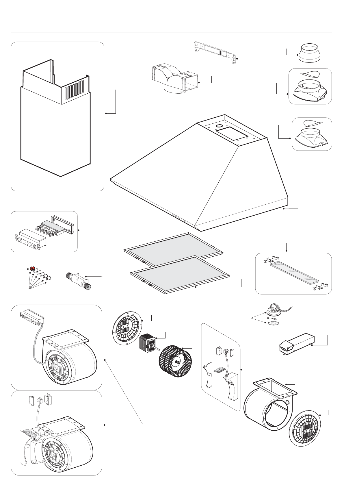
COD. DESCRIPTION
Z00SP0012000 CAP WARNING GEM
Z00SP002960D ALUMINIUM PANEL DECOR 60-LUXOR 60-ISOLA-ZENITH 60-
ZSPK0258
Z00SP0037000 MOTOR
Z0SP0038000
Z00SP0039000 TANGENTIAL CONVEYOR
ZSPK0179
ZSPK0178
Z00SP03416AB D2 BODY 60 WHITE HALOGEN LAMPS
Z00SP0441000 NR.4 FAN WHEEL
Z00SP0458000 FLANGE WITH ALUMINIUM VALVE
Z00SP049200C 5 KEYS PUSH B. CHROMIUM PLATED+WARN GEM
Z00SP0554000 NR.4 TRANSFORMER 105W
ZSPK0931
Z00SP0654000 CHIMNEY BRACKET
Z00SP0656000 AIR DEVIATOR
CHIMNEY
MOTOR SUPPORT STANDARD
CONTROL
MOTOR GROUP
HALOGEN LAMP
POSITION
12
29
30
37
38
39
110
140
341
441
458
492
554
609
654
656
Page 3

HD36C
COD.
Z00SP0012000 CAP WARNING GEM
Z00SP002960D ALUMINIUM PANEL DECOR 60-LUXOR 60-ISOLA-ZENITH 60-
ZSPK0798
Z00SP0037000 MOTOR
Z00SP0038000 MOTOR SUPPORT STANDARD
Z00SP0039000 TANGENTIAL CONVEYOR
ZSPK0179
ZSPK0178
Z00SP03416AX D2 BODY 60 INOX HALOGEN LAMPS
Z00SP0441000 NR.4 FAN WHEEL
Z00SP0458000 FLANGE WITH ALUMINIUM VALVE
Z00SP049200C 5 KEYS PUSH B. CHROMIUM PLATED+WARN GEM
Z00SP0554000 NR.4 TRANSFORMER 105W
ZSPK0931
Z00SP0654000 CHIMNEY BRACKET
Z00SP0656000 AIR DEVIATOR
CHIMNEY
CONTROL
MOTOR GROUP
HALOGEN LAMP
DESCRIPTION
POSITION
12
29
30
37
38
39
110
140
341
441
458
492
554
609
654
656
Page 4

HD36H
COD. DESCRIPTION
Z00SP0012000 CAP WARNING GEM
Z00SP002960D ALUMINIUM PANEL DECOR 60-LUXOR 60-ISOLA-ZENITH 60-
ZSPK0255
Z00SP0037000 MOTOR
Z00SP0038000 MOTOR SUPPORT STANDARD
Z00SP0039000 TANGENTIAL CONVEYOR
ZSPK0179
ZSPK0178
Z00SP03416ANG D2 BODY 60 MATT BLACK HALOGEN LAMPS
Z00SP0441000 NR.4 FAN WHEEL
Z00SP0455000 LAMP HOLDER
Z00SP0458000 FLANGE WITH ALUMINIUM VALVE
Z00SP049200C 5 KEYS PUSH B. CHROMIUM PLATED+WARN GEM
Z00SP0554000 NR.4 TRANSFORMER 105W
ZSPK0931
Z00SP0654000 CHIMNEY BRACKET 654
Z00SP0656000 AIR DEVIATOR 656
CHIMNEY
CONTROL
MOTOR GROUP
HALOGEN LAMP 609
POSITION
12
29
30
37
38
39
110
140
341
441
455
458
492
554
Page 5
Page 6
Prescriptions de montage et mode d'emploi de la hotte aspirante
Instructions on mounting and use of the cooker hood
Montagevorschrift und Gebrauchsanleitung fur die Dunstabzugshaube
Istruzioni di montaggio e d'uso della cappa aspirante-filtrante
Mod. HOTTE DECOR
HD 36
HD 51
HD 52
HD 73
HD 74
Page 7
G.
3
G.
365
0
5
096
FI
G.FIG.
FIG.
5
90
C
G
600 / 700 / 900 / 1000
8
67
C
30230
06
5
5
3
C
ax 1
in 2
ax
7
1
FI
.
4
FI
167.
2
1
7
2
4
2
Page 8

VERSIONE MOTORE ESTERNO - EXTERNAL MOTOR VERSION
VERSION MOTEUR EXTERNE - AUSFÜHRUNG FÜR MOTOR EXTERN
Fig.1
Fig.2a
W
- Cavo di collegamento in dotazione
al motore estrno
- Connecting cable supplied the
external motor
- Câble de connection fourni avec le
moteur externe
- Verbindungskabel zum externen
Motor geliefert dabei
- Scatola di connesione “X” posta
sulla cappa (fig.2a-2b).
- Connecting box “X” on the hood
(fig.2a-2b).
- Boîte de connection “X” posee sur
la hotte (fig.2a-2b).
- Box für Anschluss “X” an der Haube
angebracht (Bild 2a-2b).
- VERSIONE MOTORE ESTERNO (W)
Collegare la cappa al motore esterno indicato in fig.1
- EXTERNAL MOTOR VERSION (W)
Connect the hood to the external
x
motor,as shown in fig.1
- VERSION MOTEUR EXTERNE (W)
Relier la hoote avec le moteur externe
comme indiqué dans la fig.1
- AUSFÜHRUNG FÜR MOTOR
EXTERN (W)
Die Dunstabzugshaube an den externen
Motor anschliessen wie auf Bild 1 gezeigt
wird.
Fig.2b
x
3
Page 9

FRANCAIS
1. GÉNERALITÉS
1.1 Lire attentivement le contenu du mode
d’emploi puisqu’il fournit des indications
importantes concernant la sécurité
d’installation, d’emploi et d’entretien.Le
conserver pour d’ ultérieures consultations :
L’appareil a été réalisé comme hotte aspirante (
évacuation air à l’exterieur) ou filtrante ( recyclage
air à l’interieur) .
2. INSTRUCTIONS POUR L’INSTALLATION
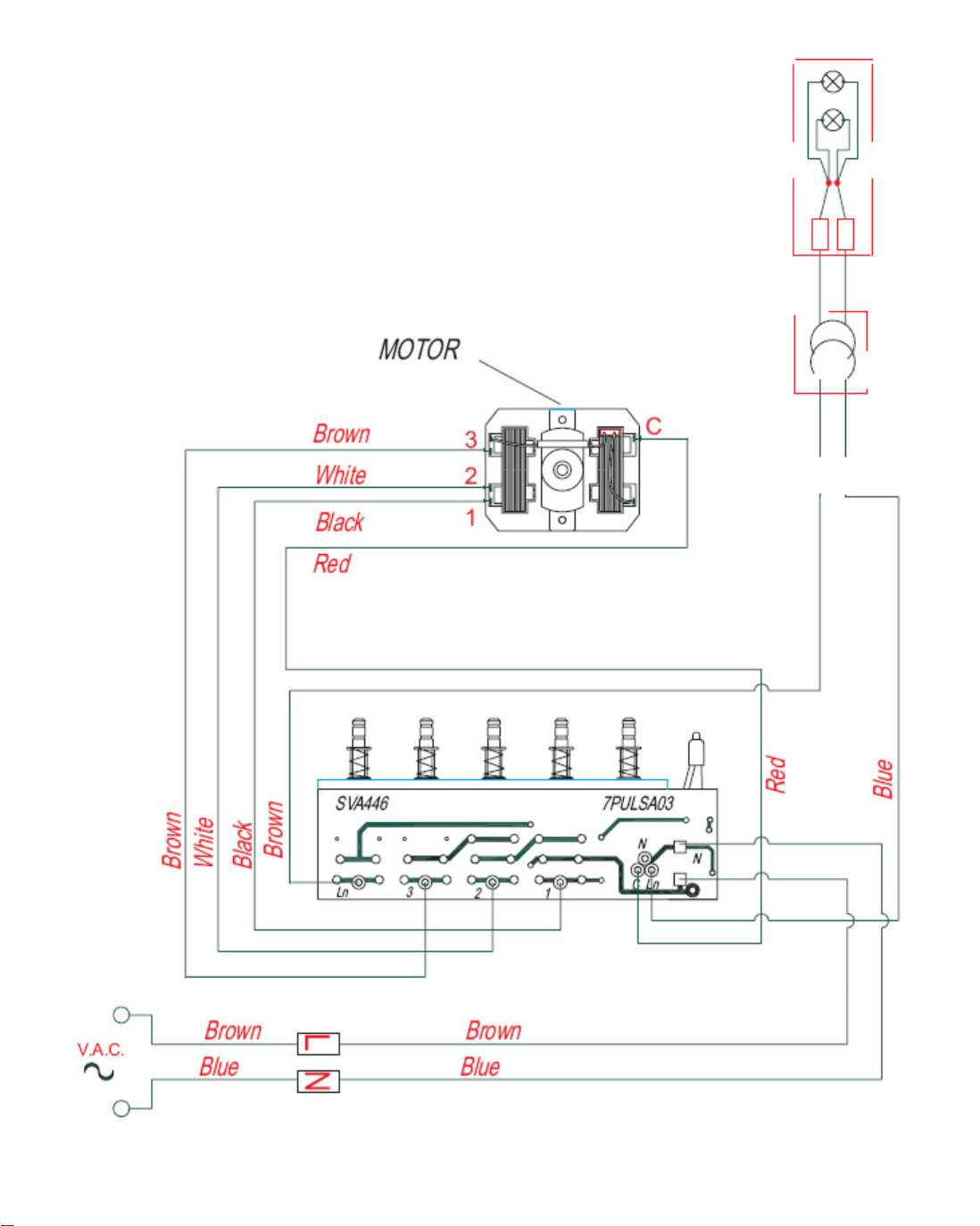
2.1 Connexion électrique
L’appareil est construit en classe II , pour cela
aucun cable ne doit être connecté avec la prise
terre.
La connection avec le réseau électrique doit être
éxécutée comme suit :
MARRON= L ligne
BLEU= N neutre
Si elle n’a pas été prévue, monter sur le cable
une fiche normalisée pour la charge indiquée sur
l’etiquette des caractéristiques. Si elle est dotée
d’une fiche, la hotte doit être installée en sorte
que la fiche soit accessible.
En cas de connection directe avec le réseau
électrique, il est nécessaire d’interposer entre
l’appareil et le réseau un interrupteur omnipolaire
avec une ouverture minimale entre les contacts
de 3 mm, proportionnel à la charge et
correspondant aux normes en vigueur.
2.2 L’appareil doit être installé à une hauteur
minimale de 650 mm des réchauds électriques,
ou 750 mm des réchauds à gaz ou mixtes.
S’il doit être utilisé un tuyau de connection
composé de deux ou plusieurs parties, la partie
superieure doit être à l’exterieur de celle inferiuere.
Ne pas relier le tuyau d’échappement de la hotte
à un conduit dans lequel circule de l’air chaud ou
employé pour évacuer les fumées des appareils
alimentés par une énergie differente de celle
électrique.
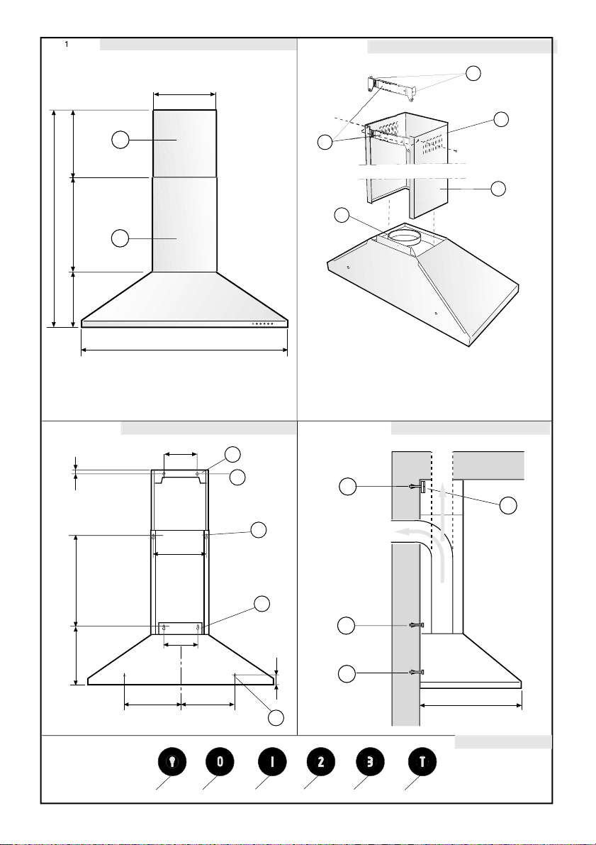
2.3 Fixation de la hotte sur le mur.
Percer les trous A-B-C-D en respectant les cotes
indiquées (fig. 3).
Pour les différents montages, utiliser les vis et
chevilles à expansion correspondant au type du
mur (ex béton armé, plâtre, etc.).
Dans le cas où les vis et chevilles sont fournies
d’origine avec le produit, vérifier qu’elles
correspondent bien au type de mur sur lequel
doit être montée la hotte.
Bloquer la bride du raccord Y à la hotte (fig. 2).
Bloquer les supports Z sur le mur grâce aux trous
A (fig.4).
Accrocher la hotte au mur en utilisant les trous C
(fig.3).
Pendre la hotte à la paroi en utilisant les trous de
sécurité D (fig.3).
2.4 Version aspirante
Raccorder, au moyen d’un tube intermédiaire, la
bride Y au trou d’évacuation (sauf pour la version
filtrante).
Enfiler le raccord supérieur E à l’intérieur du
raccord inférieur F; assembler les deux raccords
en les insérant verticalement dans la hotte. Fixer
alors le raccord inférieur F à la paroi en utilisant
les trous B (fig. 3), tirer le raccord supérieur E
vers le haut puis le bloquer à l’aide des vis sur
les trous G du support Z (fig. 2) auparavant fixé
au mur grâce aux trous A (fig. 3).
Pour transformer la hotte de la version aspirante
à la version filtrante, demander à votre revendeur
les filtres au charbon actif et suivre les
instructions de montage de la version filtrante.
2.5 Version filtrante
Installer la hotte et les deux raccords comme
indiqué dans le paragraphe traitant du montage
de la hotte en version aspirante.
Pour le montage du raccord filtrant se référer
aux instructions contenues dans le kit.
Si le kit n’est pas en dotation, le commander au
revendeur comme accessoire.
Les filtres doivent être appliqués sur le groupe
d’aspiration situé à l’intérieur de la hotte en les
centrant et en les faisant tourner de 90 degrés
jusqu’au blocage.
L’air est rejeté dans la pièce grâce aux orifices
situés sur le raccord E.
3. EMPOI ET ENTRETIEN
3.1 Nous vous recommandons de mettre la hotte
en route avant de commencer à cuisiner.
Les filtres doivent être appliqués sur le groupe
d’aspiration situé à l’intérieur de la hotte en les
centrant et en les faisant tourner de 90 degrés
jusqu’au blocage.
Le bon fonctionnement de la hotte est lié à la
fréquence des opérations d’entretien, et plus
particulièrement à l’entretien du filtre anti-graisse
et du filtre au charbon actif.
3.2 Les filtres anti graisse ont pour rôle de retenir
les particules grasses en suspension dans l’air.
4
Page 10

Ils peuvent donc se boucher plus ou moins
rapidement selon l’usage de la hotte.
Dans tous les cas, pour prévenir un éventuel
risque d’incendie, il est nécessaire de nettoyer
au moins tous les deux mois le filtre en suivant
les indications suivantes :
- Retirer les filtres de la hotte et les laver avec
de l’eau et un détergent liquide neutre, laisser la
saleté se décoller.
- Rincer abondamment à l’eau tiède et laisser
sécher.
- Les filtres peuvent également être lavés dans
le lave vaisselle.
Après plusieurs lavages des panneaux en
aluminium, on peut constater un changement de
leur couleur. Ceci n’ouvre pas droit à réclamation
afin d’obtenir un éventuel changement des
panneaux.
3.3 Les filtres au charbon actif servent à filtrer
l’air qui sera rejeté dans la pièce. Les filtres ne
sont ni lavables ni régénérables et doivent être
changés tous les trois mois au maximum. La
saturation du charbon actif dépend de l’utilisation
plus ou moins prolongée de l’appareil, du type de
cuisine effectué et de la régularité avec laquelle
est effectué le nettoyage du filtre anti graisse.
3.4 Nettoyer fréquemment tous les dépôts sur le
ventilateur et les autres surfaces, en utilisant un
chiffon imbibé d’alcool dénaturé ou de détergents
liquides neutres non abrasifs.
3.5 Si l’appareil est équipé d’un groupe
commandes elettronique (Fig. 5) les symboles
sont les suivants:
un problème “ d’inversion de flux ”. Dans ce cas
la hotte aspire l’air nécessaire à leur combustion.
La dépression dans le local ne doit pas dépasser
les 4 Pa (4 x 10
–5
bar).
Pour un fonctionnement en toute sécurité,
n’oubliez pas de prévoir une ventilation suffisante
du local.
Pour l’évacuation vers l’extérieur, veuillez vous
référer aux dispositions en vigueur dans votre
pays.
4.2 ATTENTION
Dans des circonstances déterminées les
électroménagers peuvent être dangereux.
A) Ne pas controler les filtres pendant que
la hotte est en fonctionnement
B) Nepas toucher les lampes après un emploi
prolongé de l’appareil
C) Il est interdit de cuir les aliments à la
flamme sous la hotte
D) Eviter la flamme libre, parcequ’elle est
nuisible pour les filtres et dangereuse
pour les incendies
E) Controler constemment les aliments frits
pour éviter que l’huile surchauffée
prenne feu
F) Avant d’effectuer n’importe quel entretien
déconnecter la hotte du réseau
électrique.
ON DECLINE TOUTE RESPONSABILITÉ
POUR LES EVENTUELS DÉGATS
PROVOQUÉS PAR L’INOBSERVATION DES
SUSDITES INSTRUCTIONS
A = touche ECLAIRAGE
B = touche OFF
C = touche PREMIERE VITESSE
D = touche DEUXIEME VITESSE
E = touche TROISIEME VITESSE
F = touche MINUTEUR ARRET AUTOMATIQUE
15 minutes
La fonction “minuter arrêt automatique” retarde
l’arrêt de la hotte, qui continuera de fonctionner
à la vitesse de service en cours au moment de
l’activation de cette fonction, pendant 15 minutes.
4. CONSEILS POUR LA SÉCURITÉ
4.1 Attention, lorsque dans la même pièce vous
utilisez simultanément la hotte à évacuation avec
un brûleur ou une cheminée alimentés par une
énergie autre que l’électricité, vous pouvez créer
5
Page 11

ENGLISH
1. GENERAL
1.1 Carefully read the following important
information regarding installation safety and
maintenance. Keep this information booklet
accessible for further consultations.
The appliance has been designed as a suction
version (external exhaust) or as a filter version
(internal air recycle) cooker hood.
2. INSTALLATION INSTRUCTIONS
2.1 Electric Connection
The appliance has been manufactured as a class
II, therefore no earth cable is necessary.
The connection to the mains is carried out as
follows:
BROWN = L line
BLUE = N neutral
If not provided, connect a plug for the electrical
load indicated on the description label. Where a
plug is provided, the cooker hood must be installed
in order that the plug is easily accessible.
An omnipolar switch with a minimum aperture of
3mm between contacts, in line with the electrical
load and local standards, must be placed between
the appliance and the network in the case of direct
connection to the electrical network.
2.2 The appliance must be installed at a
minimum height of 650 mm from an electric
cooker stove, or 750 mm from gas or
combined cooker stoves.
If a connection tube composed of two parts
is used, the upper part must be placed
outside the lower part.
Do not connect the cooker hood exhaust to
the same conductor used to circulate hot air
or for evacuating fumes from other
appliances generated by other than an
electrical source.
2.3 Mounting the cooker hood to the wall
Drill holes A-B-C-D according to indications
quoted in (fig. 3).
Use screws and screw anchors suitable for wall
(e.g. reinforced cement, plasterboard) for the
mounting of the cooker hood.
Where screws and screw anchors are supplied
ensure that they are suitable for the type of wall
where the cooker hood is to be mounted.
Lock in the flange connector Y to the cooker hood
(fig. 2).
Affix the bracket Z to the wall via the drill holes A
(fig.4).
Hang the cooker hood on the wall using the drill
holes C (fig.3).
Fasten the cooker hood using the fastening drill
holes D (fig.3).
2.4 Suction Version
Connect the flange Y to the discharge opening
with a connecting tube (do not carry out for filter
version).
Thread the upper connector E to the inside of the
lower connector F; hang the two connectors
inserting them vertically on the cooker hood
locking the lower connector F to the wall using
the drill holes B (fig. 3), unthread the upper
connector E towards the top, locking it in with the
appropriate screws in the drill holes G of the
bracket Z (fig. 2) previously affixed to the wall via
the drill holes A (fig. 3).
In order to transform your cooker hood from
suction version to filter version, ask your local
retailer for active carbon filters and then carry
out instructions for mounting filter version cooker
hood.
2.5 Filter Version
Install the cooker hood and the two connectors
as described in the paragraph mounting the
suction version cooker hood.
To mount the filter connector refer to instructions
included in the kit.
If the kit is not supplied, then order the kit as an
accessory from your local dealer.
The filters must be applied to the suction kit
located inside the cooker hood and centred by
rotating at 90 degrees until locked in.
The air is replaced in the environment via the
eyelets impressed on the connector E.
3. USE AND MAINTENANCE
3.1 It is recommended to operate the appliance
prior to cooking.
It is recommended to leave the appliance in
operation for 15 minutes after cooking is
terminated in order to completely eliminate
cooking vapours and odours.
The proper function of the cooker hood is
conditioned by the regularity of the maintenance
operations, in particular, the active carbon filter.
3.2 The anti-grease filters capture the grease
particles suspended in the air, and are therefore
subject to clogging according to the frequency of
the use of the appliance.
6
Page 12

In order to prevent fire hazard, it is
recommendable to clean the filter at a maximum
of 2 months by carrying out the following
instructions:
- Remove the filters from the cooker hood and
wash them in a solution of water and neutral liquid
detergent, leaving to soak.
- Rinse thoroughly with warm water and leave
to dry.
- The filters may also be washed in the
dishwasher.
The aluminium panels may alter in colour after
several washes. This is not cause for customer
complaint nor replacement of panels.
3.3 The active carbon filters purify the air that is
replaced in the environment. The filters are not
washable nor re-useable and must be replaced
at maximum every four months. The saturation
of the active carbon filter depends on the
frequency of use of the appliance, by the type of
cooking and the regularity of cleaning the antigrease filters.
Provide adequate ventilation in the
environment for a safe operation of the
cooker hood.
Follow the local laws applicable for external
air evacuation.
4.2 WARNING!!
In certain circumstances electrical appliances
may be a danger hazard.
A) Do not check the status of the filters while
the cooker hood is operating
B) Do not touch the light bulbs after
appliance use
C) Flambè cooking is prohibited underneath
the cooker hood
D) Avoid free flame, as it is damaging for
the filters and a fire hazard
E) Constantly check food frying to avoid
that the overheated oil may become a fire
hazard
F) Disconnect the electrical plug prior to any
maintenance.
3.4 Clean the fan and other surfaces of the
cooker hood regularly using a cloth moistened
with denatured alcohol or non abrasive liquid
detergent.
3.5 If the appliance is equipped with an electronic
control unit (Fig. 5) the key symbols are explained
below:
A = LIGHT
B = OFF
C = SPEED I
D = SPEED II
E = SPEED III
F = AUTOMATIC STOP TIMER – 15 minutes
The “automatic stop timer” delays stopping of
the hood, which will continue functioning for 15
minutes at the operating speed set at the time
this function is activated.
4. SAFETY PRECAUTION
4.1 Take care when the cooker hood is
operating simultaneously with an open
fireplace or burner that depend on the air in
the environment and are supplied by other
than electrical energy, as the cooker hood
removes the air from the environment which
a burner or fireplace need for combustion.
The negative pressure in the environment
must not exceed 4 Pa (4 x 10
–5
bar).
THE MANUFACTURER DECLINES ALL
RESPONSIBILITY FOR EVENTUAL DAMAGES
CAUSED BY BREACHING THE ABOVE
WARNINGS.
7
Page 13

DEUTSCH
1. ALLGEMEINES
1.1 Diese Anleitung bitte aufmerksam
durchlesen, da sie wichtige
Sicherheitshinweise zur Installation, zum
Gebrauch und zur Wartung enthält. Die
Anleitung für eventuelle zukünftige Konsultationen
aufbewahren.
Das Gerät wurde als Abzugshaube (die
angesaugte Luft wird nach aussen abgeleitet)
oder als Umlufthaube (die Luft wird in den
Raum zurückgeleitet) konzipiert.
2. INSTALLATIONSANLEITUNG
2.1 Elektroanschluss
Das Küchenhaube gehört zur Geräteklasse
II, daher muss keine der Leitungen geerdet
werden. Der Anschluss an das Stromnetz ist
folgendermassen durchzuführen:
BRAUN = L Leitung
BLAU = Neutrale Linie
Falls nicht vorhanden, muss ein Normstecker
mit den auf dem Typenschild angegebenen
Werten an das Kabel angeschlossen werden.
Wenn die Küchenhaube mit einem
Netzstecker ausgestattet ist, muss diese so
installiert werden, dass der Stecker gut
zugänglich ist.
Beim Direktanschluss an das Stromnetz
muss zwischen Gerät und Netz ein der
Netzlast und den geltenden Vorschriften
entsprechender Mehrpolstecker mit einer
Mindestöffnung von 3 mm zwischen den
Kontakten installiert werden.
2.2 Das Gerät muss in einem Mindestabstand
von 650 mm über einem Elektroherd und 750
mm über einem Gas- oder kombinierten Herd
installiert werden. Falls ein Verbindungsrohr
verwendet wird, das aus zwei oder mehr Teilen
zusammengesetzt ist, muss der obere Teil über
den unteren gestülpt werden. Auf keinen Fall darf
das Abluftrohr der Küchenhaube an ein Rohr
angeschlossen werden, in dem Warmluft zirkuliert
oder das zur Entlüftung von Geräten verwendet
wird, die an eine andere Energiequelle als an
Strom angeschlossen sind.
2.3 Wandmontage der Dunstabzugshaube
Vor der Montage ist die Schutzfolie von der
Dunstabzugshaube und vom Filtereinsatz zu
entfernen
Die Löcher A-B-C-D in die Wand bohren, dabei
müssen die angegebenen Abstände eingehalten
werden (Abb. 3).
Für die unterschiedlichen Montagen müssen
Schrauben und Dübel verwendet werden, die für
den jeweiligen Wandtyp geeignet sind ( z.B. für
Stahlbeton, Gips, etc.).
Falls die Schrauben und Dübel der Küchenhaube
beigefügt sind, ist zu prüfen, ob diese für den
Wandtyp geeignet sind, an dem das Gerät
installiert werden soll.
Den Anschlussflansch Y an die Küchenhaube
anschliessen (Abb. 2).
Den Tragbügel Z in den Bohrlöchern A an der
Wand befestigen (Abb. 4).
Die Küchenhaube an die Wand hängen, dafür die
Bohrlöcher C verwenden (Abb. 3).
Die Küchenhaube endgültig fixieren, dabei die
Sicherheitsbohrlöcher D verwenden (Abb. 3).
2.4 Abluftversion
Den Flansch Y mit Hilfe eines Anschlussrohres
an die Abluftöffnung anschliessen (diesen
Arbeitsschritt bei der Küchenhaube in
Umluftversion nicht ausführen!).
Den oberen Anschlussring E in das Innere des
unteren Anschlussringes F einsetzen; die beiden
Anschlussringe einhängen, indem sie senkrecht
die Küchenhaube eingeführt werden, dann den
unteren Anschlussring F in den Bohrlöchern B
(Abb. 3) an der Wand befestigen. Den oberen
Anschlussring E nach oben schieben und mit
den dafür vorgesehenen Schrauben in den
Löchern G des Tragbügels Z befestigen (Abb. 2),
welcher zuvor in den Bohrlöchern A an der Wand
festgeschraubt wurde (Abb. 3).
Um die Küchenhaube von der Abzugsversion in
die Umluftversion umzuwandeln, müssen Sie bei
Ihrem Fachhändler die Aktivkohlefilter anfordern;
dann die Montageanweisungen der Umlufthaube
ausführen.
2.5 Filterversion
Die Küchenhaube und die beiden Anschlussringe,
so wie im Abschnitt über die Montage der
Küchenhaube in Abluftversion angegeben,
montieren.
Bei der Montage des Filterringes müssen die im
Kit enthaltenen Anleitungen genau beachtet
werden.
Falls das Kit nicht mitgeliefert ist, muss dieses
bei Ihrem Händler als Zubehörteil angefordert
werden.
Die Filter müssen in die Ansaugeinheit im Inneren
der Küchenhaube eingesetzt werden. Die Filter
in die Mitte der Ansaugeinheit einsetzen und sie
dann um 90° bis zum Einrasten drehen.
Die Luft wird über die Schlitze, die sich im Ring E
befinden, in den Raum zurückgeleitet.
3. BENUTZUNG UND WARTUNG
3.1 Es wird empfohlen, die Küchenhaube schon
vor sämtlichen Kochvorgängen der Speisen
einzuschalten.
8
Page 14

Es wir weiterhin empfohlen, das Gerät nach
Beendigung des Kochvorganges noch 15 Minuten
weiterlaufen zu lassen, um die vollständige
Entlüftung der Kochdämpfe zu gewährleisten.
Das einwandfreie Funktionieren der
Küchenhaube hängt entscheidend von der
Sorgfalt ab, mit der die Wartungsarbeiten
durchgeführt werden, insbesondere die des
Fettfilters und die des Aktivkohlefilters.
3.2 Die Fettfilter haben die Aufgabe, die
Fettpartikel in der Abluft zu binden; die Stärke
der Verschmutzung hängt daher von der
Häufigkeit des Gebrauchs der Küchenhaube ab.
Um eine mögliche Brandgefahr zu verhindern,
muss der Filter in jedem Fall spätestens alle zwei
Monate auf die folgende Weise gereinigt werden:
- Der Abzugshaube die Filter entnehmen und
mit Wasser und einem flüssigen Neutralreiniger
abwaschen. Wenn notwenig, einweichen lassen.
- Dann gründlich mit lauwarmem Wasser
abspülen und abtrocknen lassen.
- Die Filter können auch in der
Geschirrspülmaschine gewaschen werden.
Nach mehrmaligem Waschen der Aluminiumfilter
können Farbveränderungen auftreten. Daraus
resultiert jedoch kein Anspruch auf einen
kostenlosen Ersatz der Paneele.
3.3 Die Aktivkohlefilter dienen dazu, die Luft zu
reinigen, die wieder in den Raum zurückgeführt
wird. Die Filter sind weder waschbar noch
wiederverwertbar und müssen spätestens alle
vier Monate ausgewechselt werden. Die Sättigung
der Aktivkohle hängt ab von der mehr oder
minder langen Benutzungsdauer der
Küchenhaube, von der Art der zubereiteten
Speisen und von der Regelmässigkeit, mit der
die Reinigung des Fettfilters durchgeführt wird.
3.4 Alle auf dem Lueftergehaeuse und den
anderen Teilen der Haube angesammelten
Rueckstaende sind regelmaessig mit Spiritus
oder neutralem Fluessigkeitsreiniger ohne
Scheuermittel zu entfernen
3.5 Wenn das Gerät elektronische
Bedienungselemente aufweist (Bild 5) die
SimboLbezeichnungen sind folgend
wiedergegeben:
verzögert das Anhalten der Haube, die 15 Minuten
mit der zum Zeitpunkt der Einschaltung dieser
Funktion gewählten Betriebsgeschwindigkeit
weiterläuft.
4. SICHERHEITSHINWEISE
4.1 Vorsicht ist geboten, wenn gleichzeitig eine
Abzugshaube und ein raumluftabhängiger Boiler
oder ein offenes Feuer in Betrieb sind, die von
einer anderen Energiequelle als Strom versorgt
werden, da die Küchenhaube die Raumluft
absaugt, die auch der Boiler oder das Feuer zur
Verbrennung benötigen.
Der Unterdruck im Raum darf den Wert von 4 Pa
(4 x 10⁻⁵ bar) nicht übersteigen.
Um einen sicheren Betrieb der Abzugshaube zu
gewährleisten, ist daher immer auf eine
ausreichende Belüftung des Raumes zu achten.
Bei der Ableitung der Luft nach aussen müssen
die nationalen Vorschriften eingehalten werden.
4.2 ACHTUNG!!
Elektrogeräte können unter gewissen
Umständen gefährlich sein!
A) Niemals die Filter kontrollieren, wenn die
Küchenhaube in Betrieb ist.
B) Niemals die Lämpchen nach längerem
Betrieb der Küchenhaube anfassen.
C) Es ist verboten, Speisen unter der
Abzugshaube zu flambieren.
D) Offene Flammen sind unbedingt zu
vermeiden, da diese die Filter beschädigen
und einen Brand verursachen können.
E) Beim Frittieren sind die Speisen ständig
zu kontrollieren, um die Entzündung des Öls
zu vermeiden.
F) Wird das Netzkabel dieser Haube
beschaedigt, muss es in einer vom Hersteller
zugelassenen Werkstatt ersetzt werden, da
hierzu Spezialwerkzeug benoetigt wird
G) Vor jeglichen Wartungsarbeiten
unbedingt den Netzstecker aus der
Steckdose entfernen.
FÜR SCHÄDEN, DIE AUF DIE
NICHTBEACHTUNG DER OBEN
GENANNTEN ANWEISUNGEN
ZURUCKZUFÜHREN SIND, WIRD KEINERLEI
VERANTWORTUNG ÜBERNOMMEN.
A = Taste BELEUCHTUNG
B = Taste OFF
C = Taste ERSTE GESCHWINDIGKEIT
D = Taste ZWEITE GESCHWINDIGKEIT
E = Taste DRITTE GESCHWINDIGKEIT
F = Taste TIMER AUTOMATISCHES ANHALTEN
nach 15 Minutes
Die Funktion “Timer automatisches Anhalten”
9
Page 15

ITALIANO
1. GENERALITA’
1.1 Leggere attentamente il contenuto del
presente libretto in quanto fornisce
importanti indicazioni riguardanti la sicurezza
di installazione, d’uso e di manutenzione.
Conservare il libretto per ogni ulteriore
consultazione.
L’apparecchio è stato progettato come cappa
aspirante (evacuazione aria all’esterno) o
filtrante (riciclo aria all’interno).
2. ISTRUZIONI PER L’INSTALLAZIONE
2.1 Collegamento elettrico
L’apparecchio è costruito in classe II, perciò
nessun cavo deve essere collegato alla presa di
terra.
L’allacciamento alla rete elettrica deve essere
eseguito come segue:
MARRONE = L linea
BLU = N neutro
Se non prevista, montare sul cavo una spina
normalizzata per il carico indicato nella etichette
caratteristiche. Se provvista di spina, la cappa
deve essere installata in modo tale che la spina
sia accessibile.
Nel caso di collegamento diretto alla rete elettrica
è necessario interporre tra l’apparecchio e la rete
un interruttore onnipolare con apertura minima
tra i contatti 3 mm, dimensionato al carico e
rispondente alle norme vigenti.
2.2 L’apparecchio deve essere installato ad
un’altezza minima di 650mm dai fornelli
elettrici, o 750mm dai fornelli a gas o misti.
Se dovesse essere usato un tubo di
connessione composto di due o più parti, la
parte superiore deve essere all’esterno di
quella inferiore.
Non collegare lo scarico della cappa ad un
condotto in cui circoli aria calda o utilizzato
per evacuare fumi degli apparecchi alimentati
da un’energia diversa da quella elettrica.
2.3 Montaggio della cappa alla parete
Eseguire i fori A-B-C-D rispettando le quote
indicate (fig. 3).
Per i vari montaggi utilizzare viti e tasselli ad
espansione idonei al tipo di muro (es. cemento
armato, cartongesso, ecc).
Nel caso in cui le viti e i tasselli siano forniti in
dotazione con il prodotto accertarsi che siano
idonei per il tipo di parete in cui deve essere fissata
la cappa.
Bloccare la flangia di raccordo Y alla cappa (fig.
2).
Bloccare la staffa Z al muro tramite i fori A (fig.4).
Appendere la cappa alla parete utilizzando i fori
C (fig.3).
Fissare definitivamente la cappa utilizzando i fori
di sicurezza D (fig.3).
2.4 Versione aspirante
Collegare, mediante un tubo di raccordo, la flangia
Y al foro di scarico (non eseguire nella versione
filtrante).
Infilare il raccordo superiore E all’interno del
raccordo inferiore F; appendere i due raccordi
inserendoli verticalmente nella cappa bloccando
il raccordo inferiore F alla parete utilizzando i fori
B (fig. 3), sfilare il raccordo superiore E verso
l’alto, bloccarlo con le apposite viti sui fori G della
staffa Z (fig. 2) precedentemente fissata al muro
tramite i fori A (fig. 3).
Per trasformare la cappa da versione aspirante
a versione filtrante, richiedere al vostro rivenditore
i filtri a carbone attivo e seguire le istruzioni di
montaggio della versione filtrante.
2.5 Versione filtrante
Installare la cappa e i due raccordi come indicato
nel paragrafo riguardante il montaggio della cappa
nella versione aspirante.
Per il montaggio del raccordo filtrante fare
riferimento alle istruzioni contenute nel kit.
Se il kit non è in dotazione, ordinarlo al Vs.
rivenditore.
I filtri devono essere applicati al gruppo aspirante
posto all’interno della cappa centrandoli ad esso
e ruotandoli di 90 gradi fino allo scatto d’arresto.
L’aria è rimessa nell’ambiente attraverso le asole
ricavate sul raccordo E.
3. USO E MANUTENZIONE
3.1 Si raccomanda di mettere in funzione
l’apparecchio prima di procedere alla cottura di
un qualsiasi alimento.
Si raccomanda di lasciar funzionare l’apparecchio
per 15 minuti dopo aver terminato la cottura dei
cibi, per un’evacuazione completa dell’aria viziata.
Il buon funzionamento della cappa è condizionato
dall’assiduità con cui sono effettuate le operazioni
di manutenzione, in modo particolare, del filtro
antigrasso, e del filtro al carbone attivo.
3.2 I filtri antigrasso hanno il compito di trattenere
le particelle grasse in sospensione nell’aria,
pertanto è soggetto ad intasarsi in tempi variabili
relativamente all’uso dell’apparecchio.
10
Page 16

In ogni caso, per prevenire il pericolo di eventuali
incendi, al massimo dopo 2 mesi è necessario
pulire il filtro eseguendo le seguenti operazioni:
- Togliere i filtri dalla cappa e lavarli con una
soluzione di acqua e detergente liquido neutro,
lasciando rinvenire lo sporco.
- Sciacquare abbondantemente con acqua
tiepida e lasciare asciugare.
- I filtri possono essere lavati anche in
lavastoviglie.
Dopo alcuni lavaggi dei pannelli in alluminio, si
possono verificare delle alterazioni del colore.
Questo fatto non dà diritto a reclamo per
l’eventuale sostituzione dei pannelli.
3.3 I filtri al carbone attivo servono per depurare
l’aria che verrà rimessa nell’ambiente. I filtri non
sono lavabili o rigenerabili e devono essere
sostituiti ogni quattro mesi al massimo. La
saturazione del carbone attivo dipende dall’uso
più o meno prolungato dell’apparecchio, dal tipo
di cucina e dalla regolarità con cui viene effettuata
la pulizia del filtro antigrasso.
3.4 Pulire frequentemente tutti i depositi sul
ventilatore e sulle altre superfici, usando un
panno inumidito con alcool denaturato o detersivi
liquidi neutri non abrasivi.
3.5 Se l’apparecchio è dotato di un gruppo
comandi elettronico (fig. 5) la simbologia è di
seguito riportata:
A= tasto ILLUMINAZIONE
B= tasto OFF
C= tasto PRIMA VELOCITA
D= tasto SECONDA VELOCITA
E= tasto TERZA VELOCITA
F= tasto TIMER ARRESTO AUTOMATICO 15
minuti
La funzione “TIMER ARRESTO AUTOMATICO”
ritarda l’arresto della cappa, che continuerà a
funzionare alla velocità d’esercizio in corso al
momento dell’accensione di questa funzione, di
15 minuti.
superare i 4 Pa (4 x 10
–5
bar).
Per un funzionamento sicuro, provvedere quindi
ad un’opportuna ventilazione del locale.
Per l’evacuazione esterna attenersi alle
disposizioni vigenti nel vostro paese.
4.2 ATTENZIONE!!
In determinate circostanze gli
elettrodomestici possono essere pericolosi.
A) Non cercare di controllare i filtri con la
cappa in funzione
B) Non toccare le lampade dopo un uso
protratto dell’apparecchio
C) E’ vietato cuocere cibi alla fiamma sotto
la cappa
D) Evitare la fiamma libera, perchè dannosa
per i filtri e pericolosa per gli incendi
E) Controllare costantemente i cibi fritti per
evitare che l’olio surriscaldato prenda
fuoco
F) Prima di effettuare qualsiasi
manutenzione, disinserire la cappa dalla
rete elettrica.
SI DECLINA OGNI RESPONSABILITA’ PER
EVENTUALI DANNI PROVOCATI DALLA
INOSSERVANZA DELLE SUDDETTE
AVVERTENZE
4. AVVERTENZE PER LA SICUREZZA
4.1 Fare attenzione se funzionano
contemporaneamente una cappa aspirante
e un bruciatore o un focolare dipendenti
dall’aria dell’ambiente ed alimentati da
un’energia diversa da quella elettrica, in
quanto la cappa aspirando toglie
all’ambiente l’aria di cui il bruciatore o il
focolare necessita per la combustione.
La pressione negativa nel locale non deve
11
Page 17

255, avenue Carnot
08 000 CHARLEVILLE-MEZIERES
SERVICES COMMERCIAUX
SERVICE APRES-VENTE
SERVICE PIECES DETACHEES
SERVICE GARANTIE S.G.A.
www.airlux.com
 Loading...