

Page 1

1
N450R
3T3R Wireless-N Dual Band Gigabit
User’s Manual
Router
Page 2

Copyright and Disclaimer
i
Copyright & Disclaimer
No part of this publication may be reproduced in any form or by any means, whether
electronic, mechanical, photocopying, or recording without the written consent of OvisLink
Corp.
OvisLink Corp. has made the best effort to ensure the accuracy of the information in this
user’s guide. However, we are not liable for the inaccuracies or errors in this guide. Please
use with caution. All information is subject to change without notice
All Trademarks are properties of their respective holders.
This product requires professional installation. Please do not attemp to install the
device without the necessary knowledge in regards to your country's wireless
regulations.
AirLive N450R User’s Manual
Page 3

Copyright and Disclaimer
ii
FCC Statement
Federal Communication Commission Interference Statement This equipment has been
tested and found t o co mply wi th the li mits for a Clas s B digi tal dev ic e, pur suant t o Par t 15 of
the FCC Rules.
These limits are designed to provide reasonable protection against harmful interference in
a residential installation. This equipment generates uses and can radiate radio frequency
energy and, if not installed and used in accordance with the instructions, may cause
harmful interference to radio communications. However, there is no guarantee that
interference will not occur in a particular installation. If this equipment does cause harmful
interference to radio or television reception, which can be determined by turning the
equipment off an d o n, the user is encouraged to try to correct the int e r fere nce by one of the
following measures:
n Reorient or relocate the receiving antenna.
n Increase the separation between the equipment and receiver.
n Connect the equipment into an outlet on a circuit different from that to which the
receiver is connected.
n Consult the dealer or an experienced radio/TV technician for help.
FCC Caution
Any changes or modifications not expressly approved by the party responsible for
compliance could void the user's authority to operate this equipment.
This device complies with Part 15 of the FCC Rules. Operation is subject to the following
two conditions:
1. This device may not cause harmful interference, and
2. This device must accept any interference received, including interference that may
cause undesired operation. For product available in the USA/Canada market, only
channel 1~11 can be operated. Selection of other channels is not possible.
This device and its antenna(s) must not be co-located or operation in conjunction with any
other antenna or transmitter.
IMPORTANT NOTE
FCC Radiation Exposure Statement:
This equipment complies with FCC radiation exposure limits set forth for an uncontrolled
environment. This equipment should be installed and operated with minimum distance
20cm between the radiator & your body.
AirLive N450R User ’s Manual
Page 4

Table of Contents
iii
Table of Contents
1. Introduction .............................................................................................. 1
1.1 Firmware Upgrade and Tech Support ................................................ 2
1.2 Package List ...................................................................................... 3
1.3 Features ............................................................................................ 3
1.4 Specification Table ............................................................................. 4
1.5 Hardware Installation ......................................................................... 5
1.5.1 Front View .................................................................................................... 5
1.5.2 Rear View 1.5.3 LED Indicators ................................................................... 6
1.5.4 Button Definition .......................................................................................... 7
1.5.5 How to Operate............................................................................................ 8
1.6 Wireless Operation Modes ................................................................. 9
1.6.1 AP Router (Default Setting).......................................................................... 9
1.6.2 AP Only ........................................................................................................ 9
1.6.3 WDS Repeater............................................................................................. 9
1.6.4 WDS Only .................................................................................................. 10
1.6.5 Adapter Mode ............................................................................................ 10
2. Getting Start ........................................................................................... 11
2.1 Easy Setup by Windows Utility.......................................................... 11
2.2 Easy Setup by Configuring Web UI .................................................. 19
2.2.1 Browse to Activate the Setup Wizard ......................................................... 19
2.3 Configure with Setup Wizard ........................................................... 20
3. Configuration ......................................................................................... 24
3.1 Login Web UI ................................................................................... 24
3.2 Basic Setting .................................................................................... 24
3.2.1 Network Setup ........................................................................................... 25
3.2.2 DHCP Server ............................................................................................. 38
3.2.3 Wireless 2.4G Settings .............................................................................. 40
3.2.4 Wireless 5G Settings ................................................................................. 48
3.2.5 Change Password ..................................................................................... 55
3.3 Forwarding Rules ............................................................................. 55
3.3.1 Virtual Server ............................................................................................. 56
3.3.2 Special AP ................................................................................................. 57
3.3.3 IP CAM ...................................................................................................... 58
3.3.4 Miscellaneous ............................................................................................ 58
3.4 Security Setting ............................................................................... 59
AirLive N450R User’s Manual
Page 5

Table of Contents
iv
3.4.1 Status ......................................................................................................... 60
3.4.2 Packet Filters ............................................................................................. 60
3.4.3 Domain Fitters ........................................................................................... 61
3.4.4 URL Blocking ............................................................................................. 62
3.4.5 MAC Control .............................................................................................. 63
3.4.6 Miscellaneous ............................................................................................ 64
3.5 Advanced Setting ............................................................................. 65
3.5.1 Status ......................................................................................................... 66
3.5.2 System Log ................................................................................................ 66
3.5.2 Dynamic DNS ............................................................................................ 67
3.5.3 QoS ........................................................................................................... 68
3.5.4 SNMP ........................................................................................................ 73
3.5.5 Routing ...................................................................................................... 74
3.5.6 System Time .............................................................................................. 75
3.5.7 Scheduling ................................................................................................. 76
3.5.8 IPv6 ........................................................................................................... 77
3.5.9 VLAN ......................................................................................................... 82
3.5.10 Advanced Wireless Settings .................................................................... 83
3.6 NAS ................................................................................................. 85
3.6.1 Disk Utility .................................................................................................. 85
3.6.2 Samba Server ............................................................................................ 86
3.6.3 FTP Service Configuration ......................................................................... 86
3.6.4 Access Control ........................................................................................... 87
3.6.5 iTunes Server ............................................................................................ 87
3.6.6 Download Assistant ................................................................................... 88
3.6.7 Download Status ........................................................................................ 92
3.6.8 Web HDD ................................................................................................... 93
3.7 Tool Box ........................................................................................... 93
3.7.1 System Info ................................................................................................ 94
3.7.2 USSD ......................................................................................................... 94
3.7.3 Firmware Upgrade ..................................................................................... 95
3.7.4 Backup Setting........................................................................................... 95
3.7.5 Reset to Default ......................................................................................... 96
3.7.6 Reboot ....................................................................................................... 96
3.7.7 Miscellaneous – Wak e on LAN & Ping ....................................................... 96
Appendix A: Troubleshooting................................................................... 98
AirLive N450R User ’s Manual
Page 6

1. Introduction
1
1
Introduction
1.
Thank you for purchase of this AirLive product. AirLive N450R is a 802.11n concurrent
dual band broadband router with USB slots for USB storage and 3G USB modem
support. It features Gigabit LAN and WAN ports that can work with 10/100Mbps devices
also. In this guide, you will learn how to configure N450R's extensive functions.
AirLive N450R User’s Manual
Page 7

1. Introduction
2
1.1 Firmware Upgrade and Tech Support
If you encounter a technical issue that can not be resolved by information on this guide,
we recommend that you visit our comprehensive website support at www.airlive.com.
The tech support FAQ are frequently updated with latest information.
In addition, you might find new fir mwares th at either i ncrease softw are functi ons or prov ide
bug fixes for N450R. You can reach our on-line support center at the following link:
http://www.airlive.com/support/support_2.jsp
Since 2009, AirLive has added the “Newsletter Instant Support System” on our website.
AirLive Newsletter subscribers receives instant email notifications when there are new
download or tech support FAQ updates for their subscribed airlive models. To become an
AirLive newsletter member, please visit: http://www.airlive.com/member/member_3.jsp
AirLive N450R User ’s Manual
Page 8
3
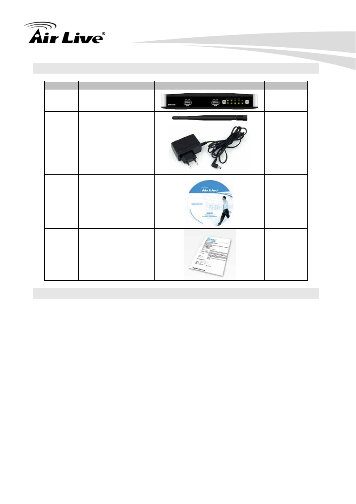
Items
Description
Contents
Quantity
1
N450R main unit
1
2
Antenna
3
3
Power adapter
1
4
CD 1
5
Quick Start Guide
1
1.2 Package List
(12V ,1.5A)
1. Introduction
1.3 Features
n Supports Wireless a/b/g/n Dual Band Standard
n 450Mbps at 5GHz and 300Mbps at 2.4GHz
n 5GHz and 2.4GHz at the same time
n 3T3R Beam Forming radio, smart antenna technology
n Multi-Wall and Multi-Level environment
n 4 x Gigabit LAN and 1 x Gigabit WAN Ports
n Support WAN and 3G Failover or Load Sharing
n 2 x USB 2.0 port for external storage and 3G dongle
n Wireless Encryption: WEP, WP A/WPA2, WPA-PSK/WPA2-PSK
n Support WPS Button
n Supports QoS bandwidth, Web HDD, Internet scheduling
n Supports Smartphone tethering to share 3G bandwidth
n Supports UPnP Media server, iTunes Server
n AirLive IPCAM Plug-and-Play
n IPv6, SNMP, Static Route, RIP
n UPnP, Virtual Sever, ALG, DMZ and SPI Firewall etc
n Supports IPSec, L2TP and PPTP VPN Pass-Through
AirLive N450R User’s Manual
Page 9

4
Device Interface
Ethernet WAN
RJ-45 port,10/100/1000Mbps, auto-MDI/MDIX
Ethernet LAN
RJ-45 port, 10/100/1000Mbps, auto-MDI/MDIX x 4
USB WAN
USB 2.0 for 3G/3.5G/4G USB dongle
USB Sharing
USB 2.0 for file sharing
Antenna
External antenna x 3
WPS Button
For WPS connection
Wireless On/Of f Butt on
Enable /Disable Wireless Radio
Reset Button
Reset router setting to factory default
LED Indication
St atus / 2.4GHz/5GHz / USB1/USB2/ WAN / LAN1 ~
LAN4
Power
DC 12V/1.5A switching power adapter
Wireless LAN (WiFi)
Standard
IEEE 802.11n 2.4GHz(2x2) /5GHz (3x 3)
compliance
SSID
SSID broadcast or in stealth mode
Channel
Auto-selection, manually
Security
WEP, WPA, WPA-PSK, WPA2, WPA2-PSK
WPS
WPS (Wi-Fi Protected Setup)
WMM
WMM (Wi-Fi Multimedia)
Functionality
Ethernet WAN
PPPoE, DHCP client, Static IP, PPTP, L2TP
WAN Connection
Auto-reconnect, dial-on-deman d, manual l y
IPv6 support
Dual stack IPv6 support
One-to-Many NAT
Virtual server, special application, DMZ
NAT Session
Support NAT session up to 20,000 sessions
SPI Firewall
IP/Service filter, URL blocking, MAC control
DoS Protection
DoS (Deny of Service) detection and protection
Routing Protocol
Static route, dynamic route (RIP v1/v2)
Storage/File Sharing
FAT16/FAT3 2, EXT2, NTFS ( Read only)
Samba server, FTP server
Media server
UPnP AV media server, iTunes server
Scheduling Download
management
FTP, HTTP , BitTorrent
Management
SNMP, UPnP IGD, syslog, DDNS
Administration
Web-based UI, remote login, backup/restore setting
1.4 Specification Table
1. Introduction
AirLive N450R User ’s Manual
Page 10
5
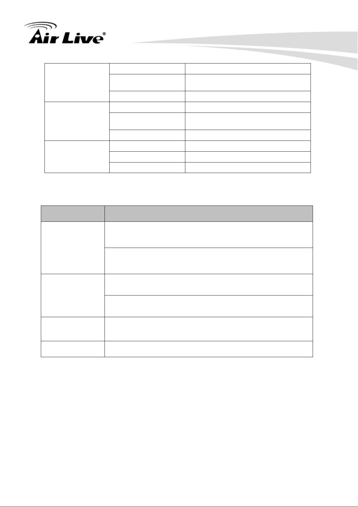
Environment & Certification
Package Information
Package dimension (mm)
Package weight (g)
Operation Temp.
Temp.: 0~40oC, Humidity 10%~90%
non-condensing
Temp.: -10~70oC, Humidity: 0~95%
non-condensing
EMI Certification
CE/FCC compliance
RoHS
RoHS compliance
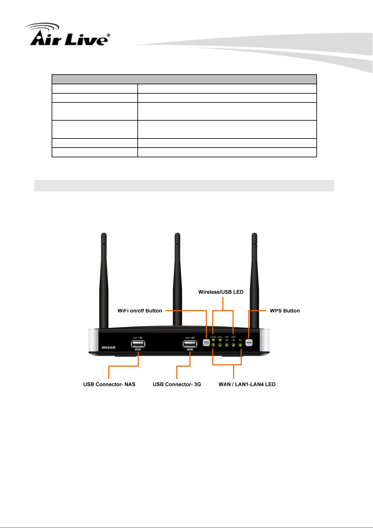
1.5 Hardware Installation
1.5.1 Front View
1. Introduction
AirLive N450R User’s Manual
Page 11
6
LED
Indicator
Description
Green and flash once
per second
Green and S teady On
An error occurred
Device is powered off or an error
occurred
Ethernet WAN connection is
established
Data packet tr ans f er red v i a Ethern et
WAN
Ethernet LAN connection is
established
Data packet tr ansferred via Ethernet
LAN
Data packet tr ans f er red v i a 2.4G
WiFi
Green and Fast
Blinking
OFF
2.4GHz wireless radio is disabled
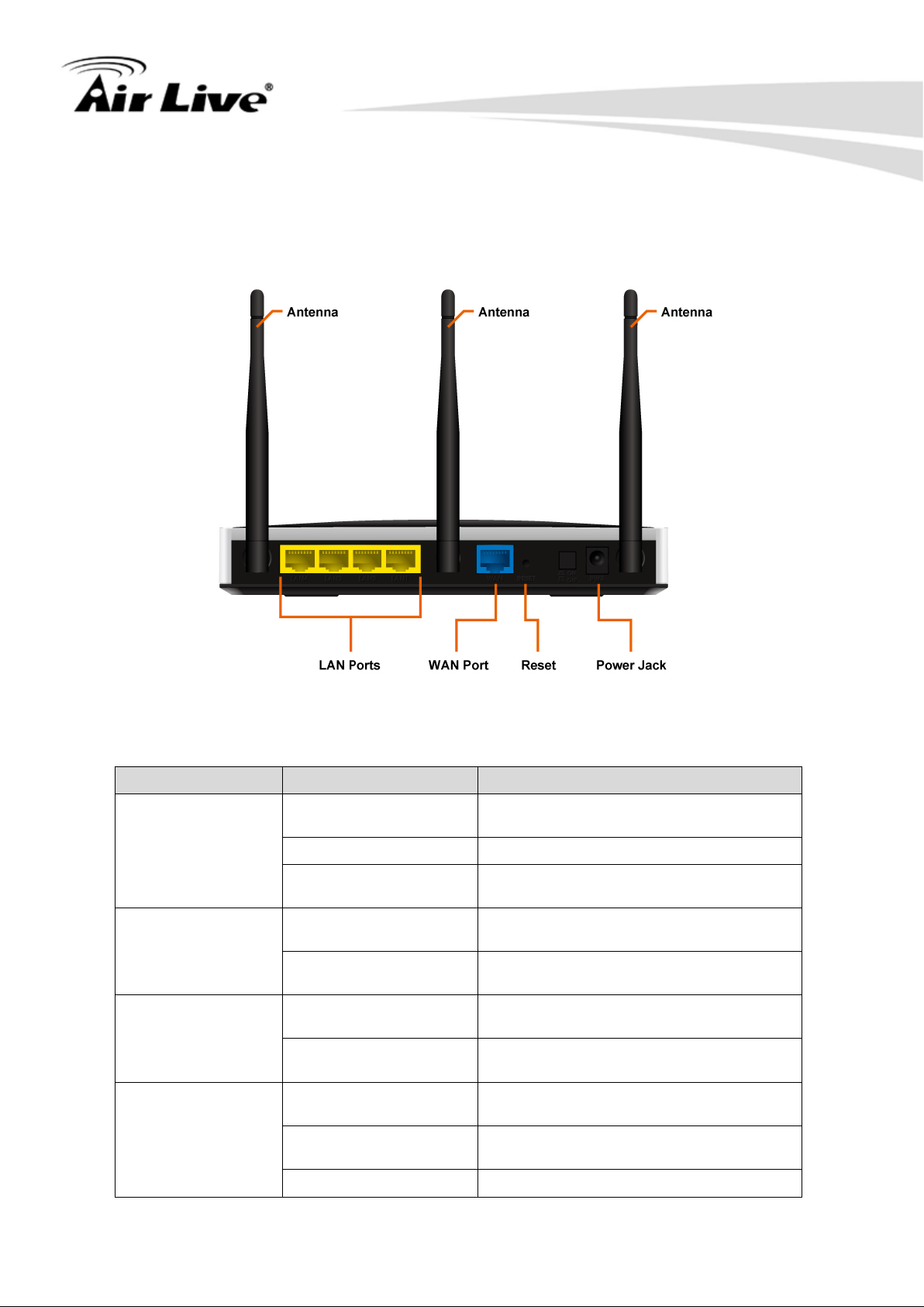
1.5.2 Rear View
1. Introduction
1.5.3 LED Indicators
Status
Ethernet WAN
Ethernet LAN 1~4
2.4GHz
This device is working
OFF
Green and S teady On
Green and Blinking
Green and S teady On
Green and Blinking
Green and Blinking
In WPS PBC mode
AirLive N450R User ’s Manual
Page 12
1. Introduction
7
Green and Blinking
Data packet tr ans f er red v i a 5G WiFi
Green and Fast
Blinking
Data packet tr ans f er red v i a att ac he d
USB storage device (e.g. USB drive)
Green and Blinking
Data packet tr ans f er red v i a 3G W A N
Continually press 3 seconds to enter WPS PBC mode for 2.4G
Continually press 8 seconds to enter WPS PBC mode for 5G
Continually press 3 seconds to switch on/off for 2.4G wireless
Continually press 8 seconds to switch on/off for 5G wireless
5GHz
OFF 5GHz wireless radio is disabled
Green and S teady On An external USB storage is attached
NAS
Green and Blinking
OFF No USB storage is attached
Green and S teady On 3G connection is established
3G
OFF 3G connection is not est abli s h ed
1.5.4 Button Definition
Button Description
wireless
WPS
In WPS PBC mode
wireless
radio
WiFi on/off
radio
Reset
Continually press 6 seconds to reset device settings to factory
default
Power Push down the button to turn on the power
AirLive N450R User’s Manual
Page 13

8
1.5.5 How to Operate
DO NOT connect the router to power before performing the installation steps
below.
Step 1: Screw the antenna in a clockwise direction to the back pan el of the unit.
1. Introduction
Step 2: Plug the RJ45 cable into LAN port 1~4 and connect with your PC or NB.
Step 3: Plug your RJ-45 into the WAN port and connect with your xDSL modem.
Step 4: Plug the power jack into it.
AirLive N450R User ’s Manual
Page 14

9
Step 5: Power ON.
Step 6: Prepare a USB Storage and then plug into the USB port.
1. Introduction
1.6 Wireless Operation Modes
1.6.1 AP Router (Default Setting)
In this mode, you can share your 3G Internet connection and/or broadband connection. If
you do not have a 3G USB dongle, you can still share your ADSL modem, xDSL mdoem,
or Cable Modem connections. If you have both 3G and Broadband, you can use both for
connection backup.
1.6.2 AP Only
When operating in the Access Point mode, the N450R becomes the center hub of the
wireless network. All wireless cards and clients connect and communicate through N450R.
This type of network is known as “Infrastructure Network”. Other N450R can connect to
AP mode through “Adapter Mode”.
1.6.3 WDS Repeater
In WDS Repeater mode, the N450R functions as a repeater that extends the range of
remote wireless LAN. In this mode, the remote Access Point must have WDS (Wireless
Distribution System) capability. If you require the PC’s MAC addresses to be preserved
when the data pass thr ough the Re peater, i t is necessary to use the WDS R epeater mode.
Because the radio is divided into WDS + AP mode, the Repeater mode will have less
performance and dista nce.
AirLive N450R User’s Manual
Page 15

1. Introduction
10
1.6.4 WDS Only
This mode is also known as “WDS Pure MAC Bridge mode”. When configured to
operate in the W ireless Distribution System (WDS) Mode, the N450R provides bridging
functions with remote LAN networks in the WDS system. Each bridge can only associate
with maximum of 4 other bridges in the W DS configuration. This mode is best used when
you want to connect LAN networks together wirelessly. This mode usually delivers faster
performance than infrastructure mode.
1.6.5 Adapter Mode
This mode is also known as “Client” mode. N450r acts as if it is a wireless adapter to
connect with a remote Access Point. Users can attach a computer or a router to the LAN
port of N450R to get network access. This mode is often used by WISP on the
subscriber’s side.
AirLive N450R User ’s Manual
Page 16
2. Getting Start
11
2
Getting Start
2.
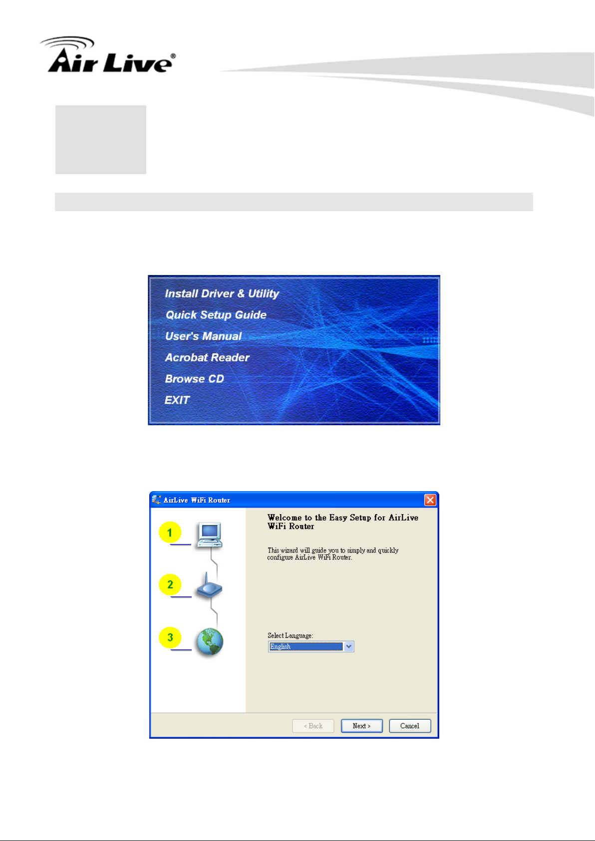
2.1 Easy Setup by Windows Utility
Step 1
Install the Easy Setup Utility from the provided CD. Click the “Install Driver & Utility” and
then follow the steps to configure the device.
Step 2
Select Language then cli c k “Next” to continue.
AirLive N450R User’s Manual
Page 17

12
Step 3
Then, click the “Wizard” to continue.
2. Getting Start
Step 4
Click “Next” to continue.
AirLive N450R User ’s Manual
Page 18
13
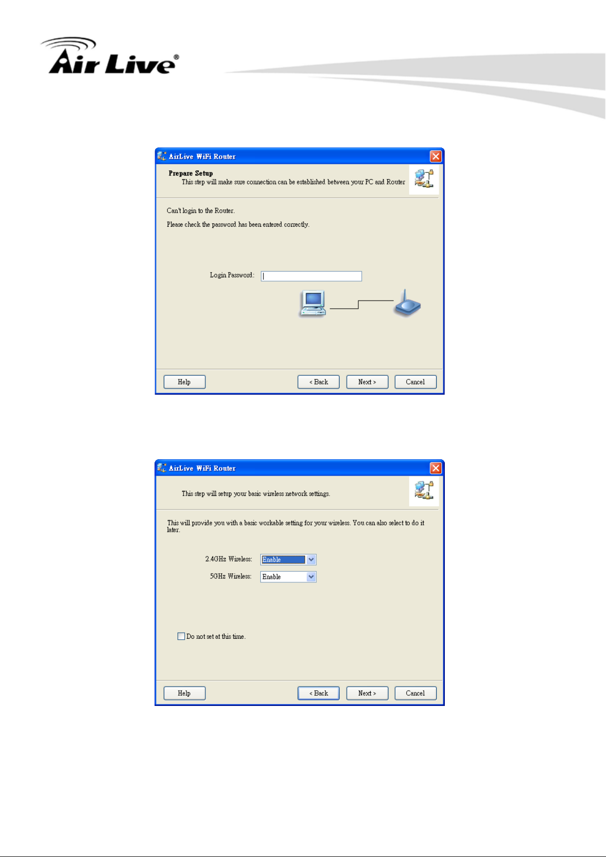
Step 5
Type-in password and then click “Next”. Default password is airlive.
2. Getting Start
Step 6
Configure the wireless interface and then click “Next”.
AirLive N450R User’s Manual
Page 19
2. Getting Start
14
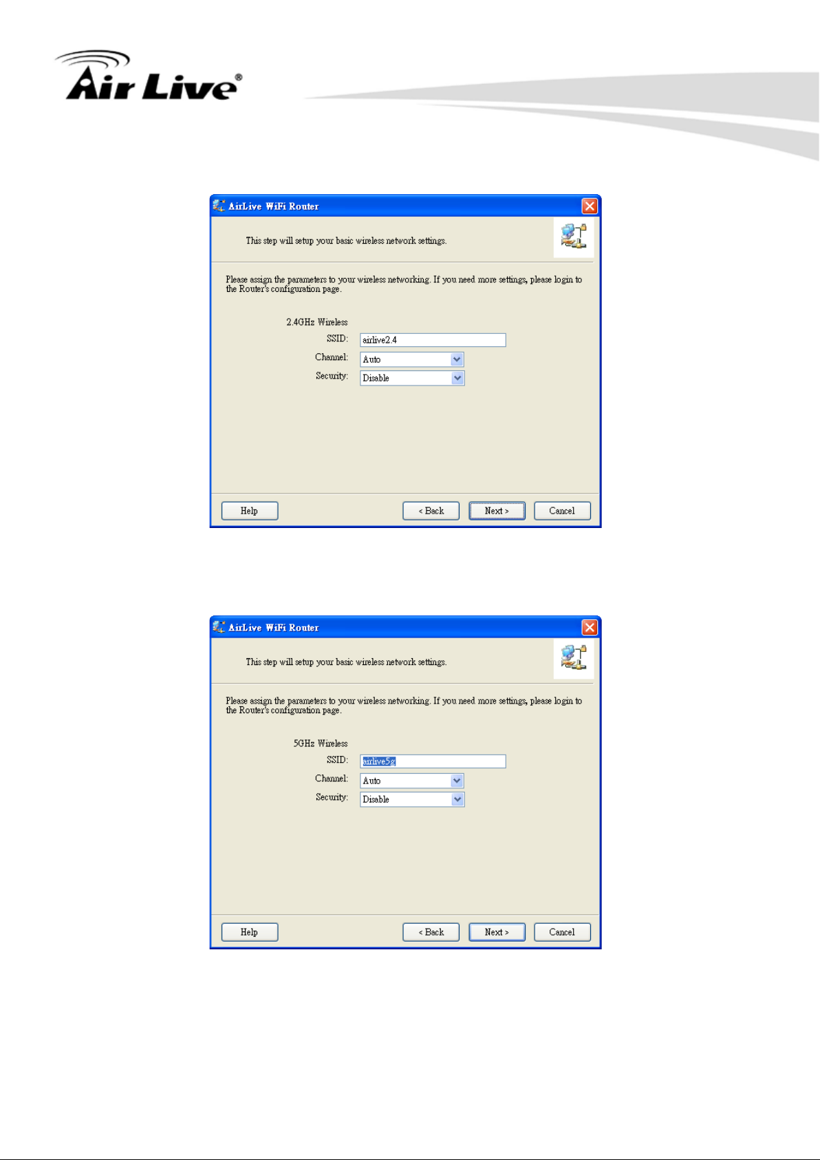
Step 7
Configure 2.4GHz wireless interface SSID, Channel and Security, and then click “Next”.
Step 8
Configure 5GHz wireless interface SSID, Channel and Security, and then click “Next”
AirLive N450R User ’s Manual
Page 20
15
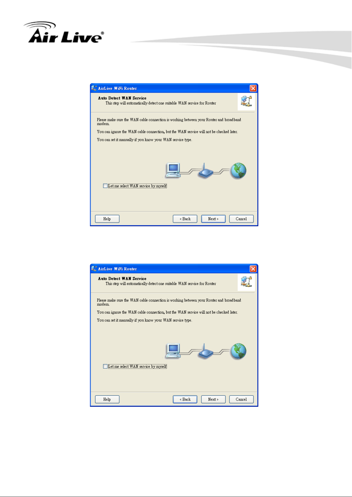
Step 9
Click Next.
2. Getting Start
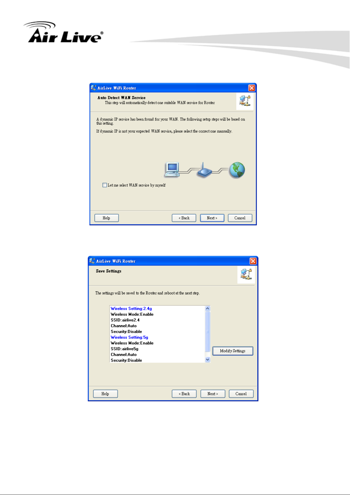
Step 10
Click “Next” to detect the W AN automatically.
AirLive N450R User’s Manual
Page 21
16
Step 11
Click “Next”.
2. Getting Start
Step 12
Click “Next”.
AirLive N450R User ’s Manual
Page 22
17
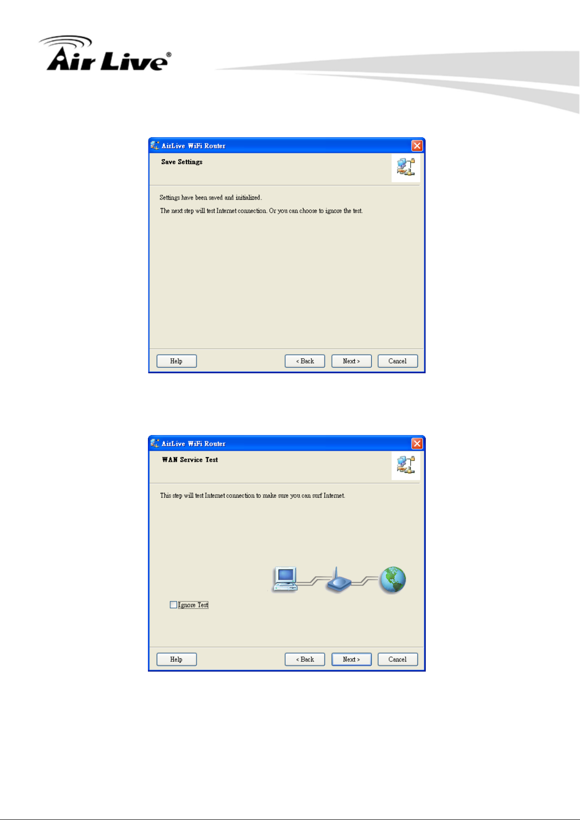
Step 13
Click “Next”.
2. Getting Start
Step 14
Click “Next” to test the internet connection.
AirLive N450R User’s Manual
Page 23
2. Getting Start
18
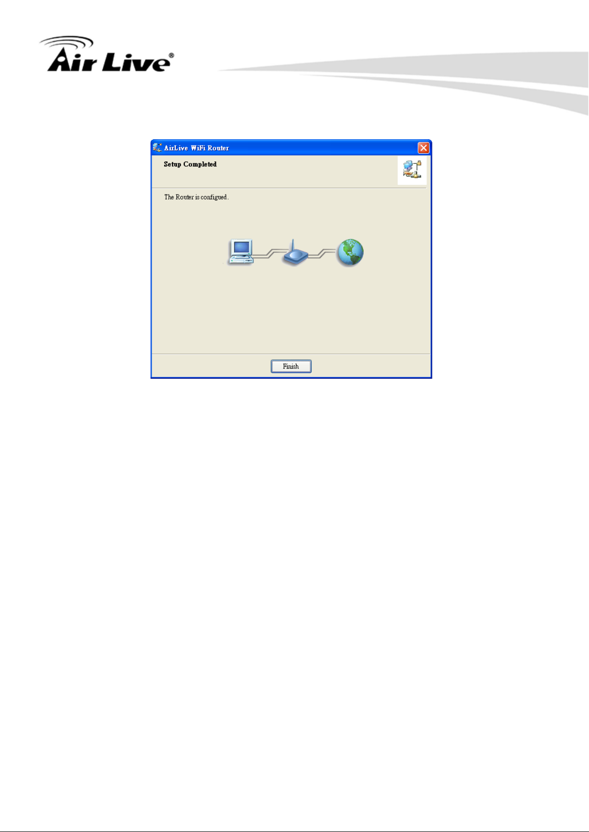
Step 15
You have completed t he con figur atio n. Cli ck “Fi nish” and you c an sur f on the int ernet now .
AirLive N450R User ’s Manual
Page 24
2. Getting Start
19
2.2 Easy Setup by Configuring Web UI
You can also browse UI of the web to configure the device
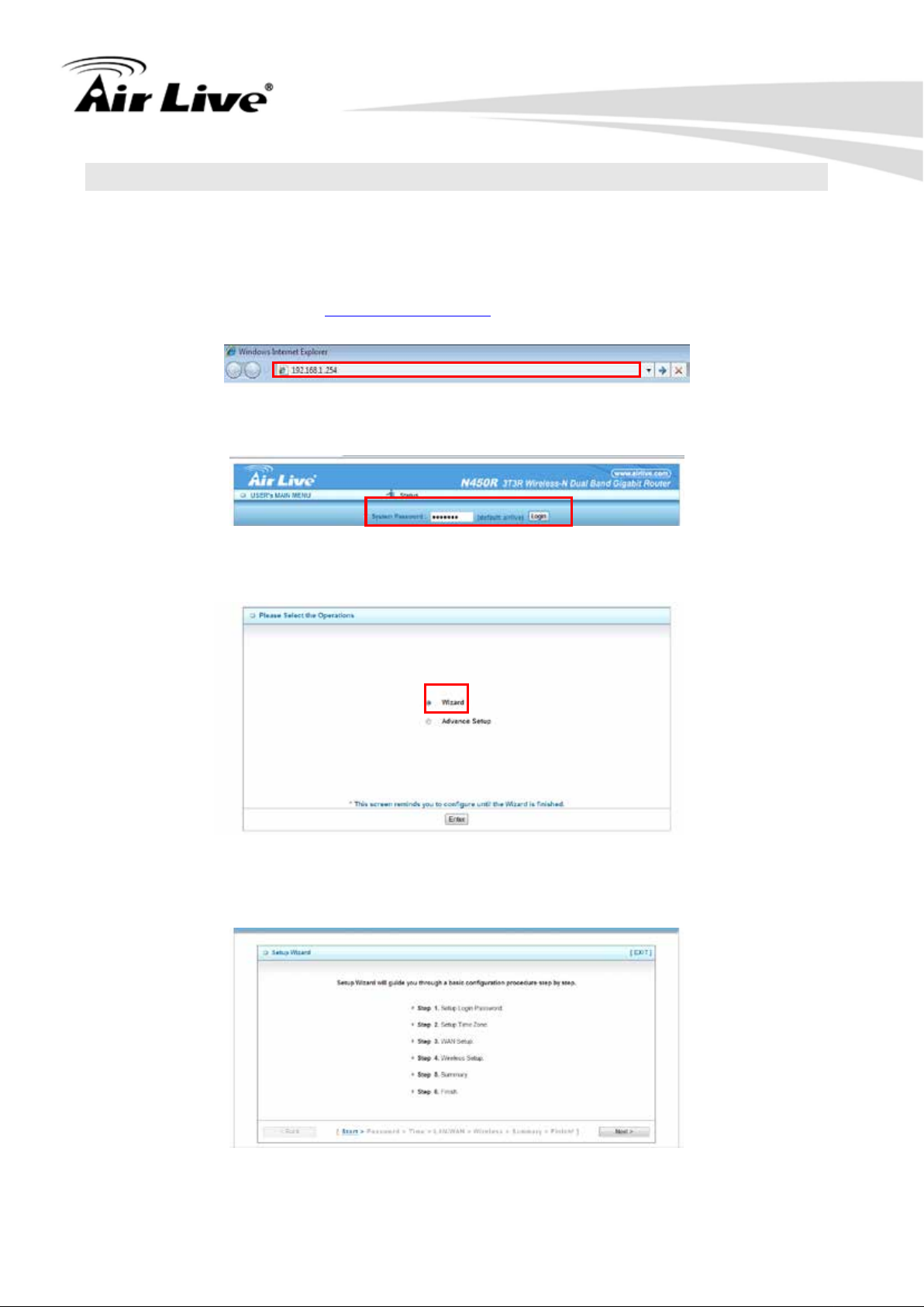
2.2.1 Browse to Activate the Setup Wizard
n Type in the IP Address (http://192.168.1.254)
n Type the default password ‘airlive’ in the System Password and then click ‘login’
button.
n Select “Wizard” and then “Enter” for basic settings in simple way.
n Press “Next” to start the Setup Wizard.
AirLive N450R User’s Manual
Page 25
20
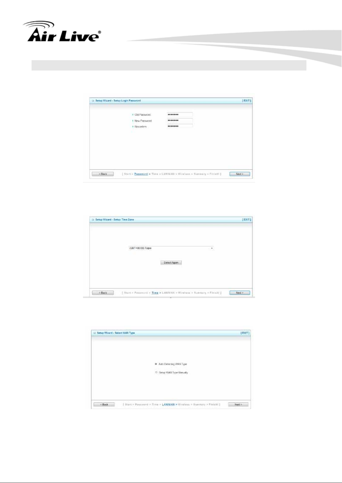
2.3 Configure with Setup Wizard
Step 1: Setup Login Password
You can change the admin password here, clicks “Next” to continue.
Step 2: Setup Time Zone
Select Time Zone, clicks “Next” to continue.
2. Getting Start
Step 3: Select WAN Type
Choose “Auto Detecting” or “Manually” Setup WAN Type.
AirLive N450R User ’s Manual
Page 26
2. Getting Start
21
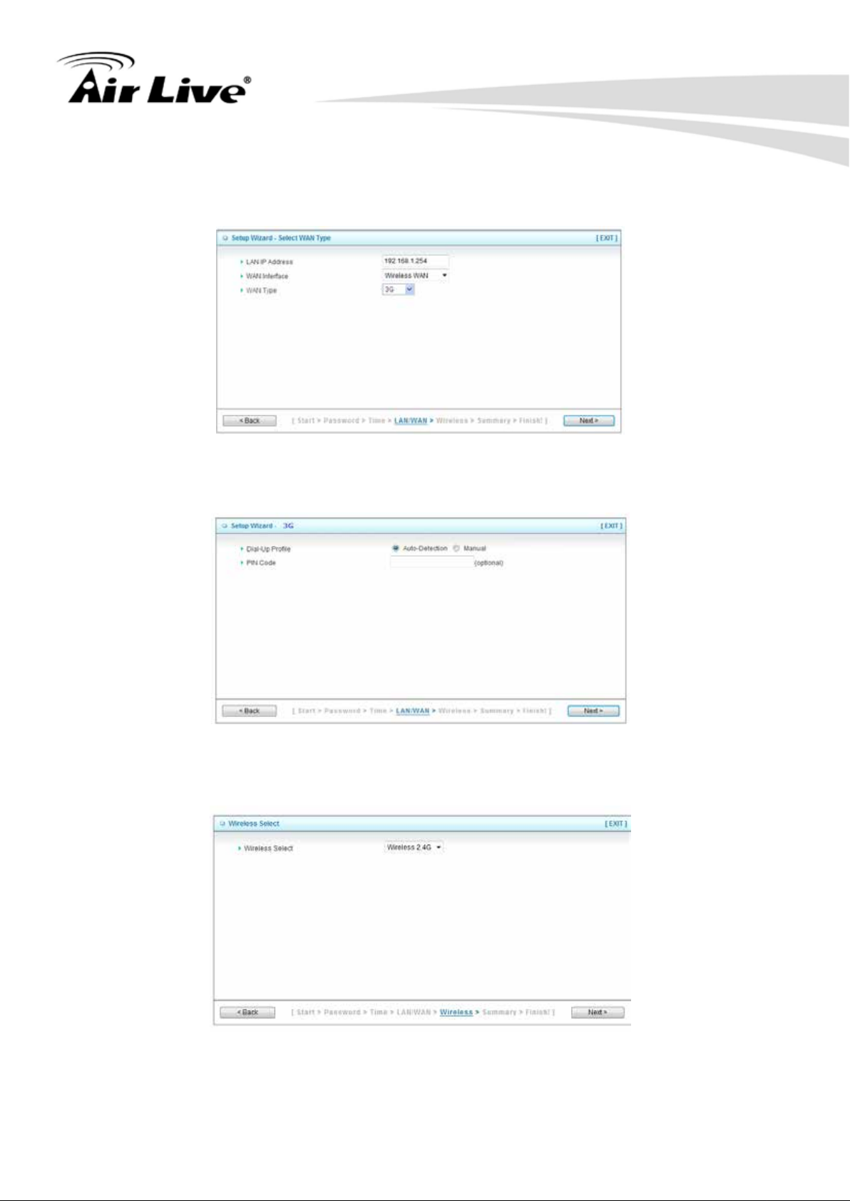
Step 4: Select WAN Type
If you want to use 3G service as the main Internet access, please set the WAN interface
as Wireless WAN and the WAN type as “3G”, and then click Next to continue.
Step 5: For 3G Mode
Select Auto-Detection, and then click Next to continue.
Step6: Wireless Settings
Set up your Wireless Network, select which wireless band you want to configure.
(e.g. Wireless 2.4G)
AirLive N450R User’s Manual
Page 27
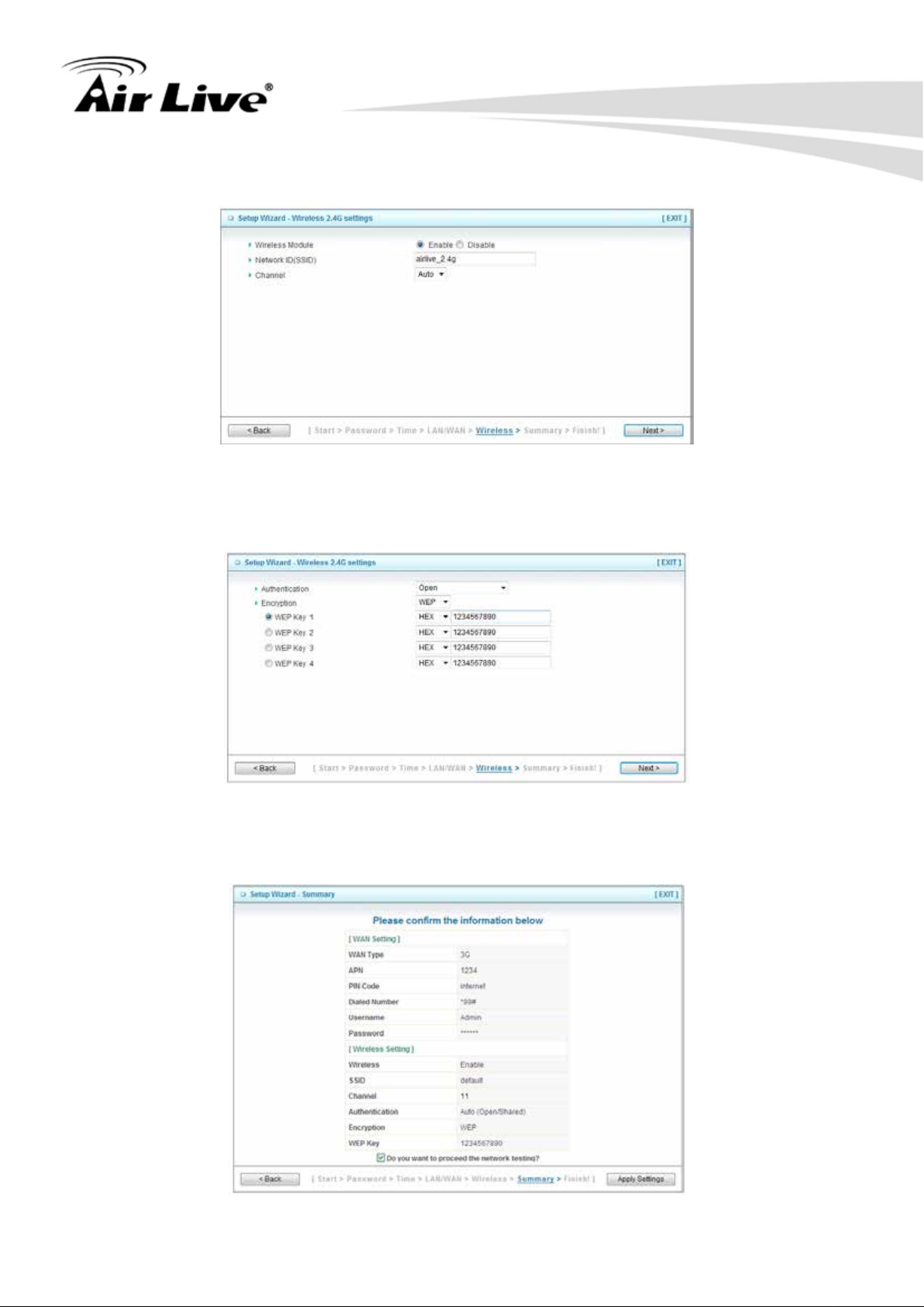
22
Step 7: Wireless 2.4G Settings
Setup your SSID and Wireless Channel.
Step 8
Setup Wireless Authentication and Encryption, then click Next to continue.
2. Getting Start
Step 9
Apply your Setting.
Clicks Apply Setting if finished, or click Back to previous settings.
AirLive N450R User ’s Manual
Page 28
2. Getting Start
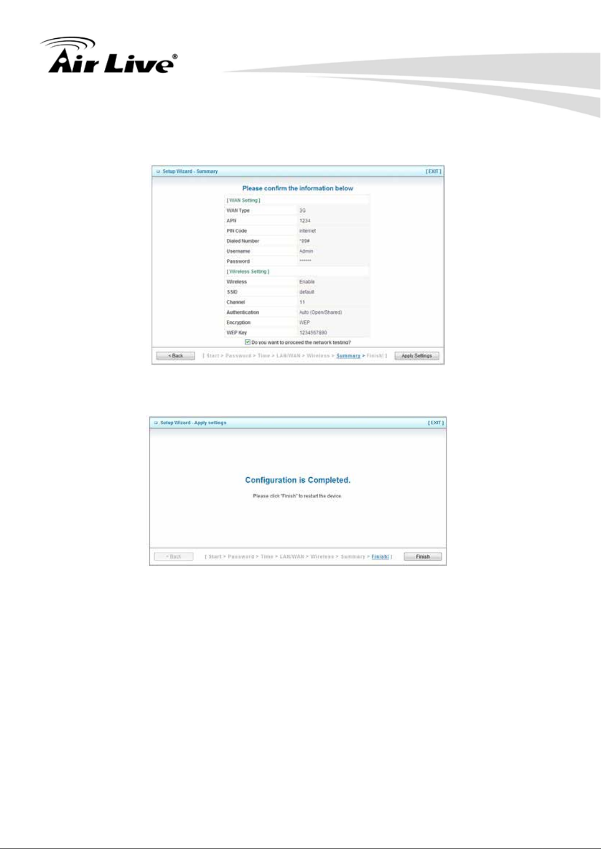
23
Step 10
Check the information again, click “Apply Setting” to finish all settings or “Back” to the
previous settings.
Step 11
Click “Finish” to complete it.
AirLive N450R User’s Manual
Page 29

3. Configuration
24
3
Configuration
3.
3.1 Login Web UI
Whenever you want to configure your network or this device, you can access the
Configuration Menu by opening the web-browser and typing in the IP Address of the
device. The default IP Address is: 192.168.1.254.
Enter the default password “airlive” in the System Password and then click ‘login’ button.
Then, you can browse the “Advanced” configuration pages for configuring this device.
3.2 Basic Setting
There are four options: Network Setup, DHCP Server, Wireless and Change
Password.
AirLive N450R User ’s Manual
Page 30
3. Configuration
25
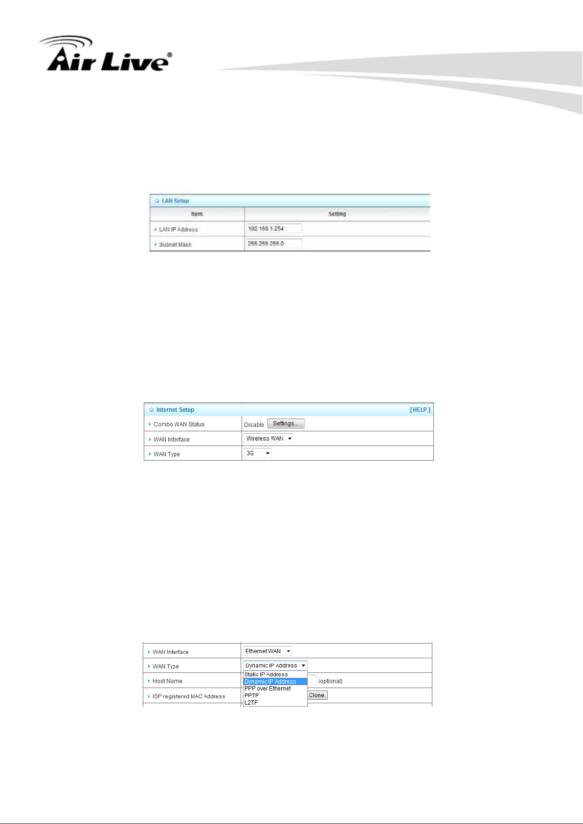
3.2.1 Network Setup
There are two ways to configure the network, respectively LAN Setup and Internet
setup.
n LAN Setup
1. LAN IP Address
The local IP address of thi s dev i ce, the c ompu ter on y our netw ork must us e the LAN IP
address of this device as their Default Gateway. You can change it if necessary.
2. Subnet Mask
Input your Subnet mas k . ( Al l devices in the network must have the s ame s ub net mask.)
The defaul t subnet mask is 255.255.255.0.
n Internet Setup
1. Combo WAN Status
Display status of combo WANS. With Combo WAN feature, you can choose one
primary WAN connection, and set another WAN connection for backup. Otherwise,
you can also choose “Load Sharing” to use Ethernet WAN and 3G WAN
simultaneously. The combo WAN status will be showed here. Press “Settings” button
to configure this feature.
2. WAN Interface
Select Ethernet WAN or Wireless WAN to continue.
n Ethernet WAN
AirLive N450R User’s Manual
Page 31

3. Configuration
26
n Wireless WAN
1. WAN Type
WAN type of your Internet connection, select 3G and iBurst. You can choose a
correct one from the following options.
(A) 3G
This device supports different WAN types of connection for users to connect to remote
wireless ISP, such as 3G (W CDMA, HSxPA, HSPA+, CDMA2000, EV-DO, TD-SCDMA),
iBurst, or Wi-Fi Hotspot.
*For 3G/Smarphone Tethering compatibility list, please visit the N450R product page on
www.airlive.com.
NOTE: You need to insert USB modem card for 3G WAN connections.
1. WAN Type
Choose 3G for WAN connection.
2. Dial-Up Profile
Please select Auto-Detection or Manual. You can choose “Auto-Detection”, and the
router will try to detect and configure the required 3G service settings automatically.
Otherwise, you can select “Manual”, and manually fill in the required 3G service
settings provided by your carrier or ISP.
AirLive N450R User ’s Manual
Page 32

27
3. Connection Control
There are 3 options to start connection:
n Auto Reconnect (Always-on)
The device will always try to link to Internet.
n Connect-on-demand
The device won’t try to connect to Internet until LAN PCs or devices try to go to
Internet. Once Internet connection is established, this device will drop the
connection if maximum idle time is reached.
n Manually
The device won’t try to connect to Internet until users press “connect” button at
Status page. Once Internet connection is established, this device will drop the
connection if maximum idle time is reached.
4. Allowed Connection Time
You can limit WAN connection in a period of time if required.
3. Configuration
5. Keep Alive
There are three options for keep alive feature as below.
n Disable
Disable keep alive feature.
n LCP Echo Request
The device will constantly send LCP packets for keeping alive. Enter the time
interval and the maximum failure count.
n Ping Remote Host
Enter the Remote host IP address and the time interval to send the ping packets
for keeping alive.
6. NAT Disable
You can disable NAT feature if required.
7. IGMP Proxy
Enable this feature allows multicast stream (e.g. IPTV stream) to pass-through this
device.
NOTE: The items with * above are only available when choosing Manual for Dial-up
Profile.
AirLive N450R User’s Manual
Page 33

28
(B) iBurst
NOTE: You need to insert USB modem card for iBurst WAN connections.
3. Configuration
1. WAN Type
Choose iBurst for WAN connection.
2. Account
Enter the User Name for iBurst connection.
3. Password
Enter new Password for iBurst connection.
4. Primary DNS
You can assign a Primary DNS server if required. (Optional)
5. Secondary DNS
You can assign a Secondary DNS server if required. (Optional)
6. Connection Control
There are 3 options to start connection:
n Auto Reconnect (Always-on)
The device will always try to link to Internet.
n Connect-on-demand
The device won’t try to connect to Internet until LAN PCs or devices try to go to
Internet. Once Internet connection is established, this device will drop the
connection if maximum idle time is reached.
n Manually
The device won’t try to connect to Internet until users press “connect” button at
Status page. Once Internet connection is established, this device will drop the
connection if maximum idle time is reached.
AirLive N450R User ’s Manual
Page 34

3. Configuration
29
7. Maximum Idle Time
The amount of ti me o f i nac ti v i ty before disconnecting Intern et connection. Set it to zero,
or choosing “Auto-reconnect” mode to disabl e this featur e .
8. Service Name
Input the service name if your ISP requires it. (Optional)
9. Assigned IP Address
Input a IP address if your ISP requires it. (Optional)
10. Maximum Transmission Unit (MTU)
You can change MTU value if required. The default MTU value is set to 0 (auto).
11. NAT disable
You can disable NAT feature if required.
12. IGMP Proxy
Enable this feature allows multicast stream (e.g. IPTV stream) to pass-through this
device.
(C) Static IP Addr ess
1. WAN Type
Choose Static IP Address.
2. WAN IP Address
Input the IP address you got from ISP.
3. Subnet Mask
Input the subnet mask of IP address you got from ISP.
4. WAN Gateway
Input the IP address of WAN gateway you got from ISP.
5. Primary DNS
Input the IP address of primary DNS you got from ISP.
6. Secondary DNS
Input the IP address of secondary DNS you got from ISP.
AirLive N450R User’s Manual
Page 35

30
7. NAT disable
You can disable NAT feature if required.
8. IGMP Proxy
Enable this feature allows multicast stream (e.g. IPTV stream) to pass-through this
device.
(D) Dynamic IP Address
3. Configuration
1. WAN Type
Choose Dynamic IP Address.
2. Host Name
Optional, required by some ISPs, for example, @Home.
3. ISP registered MAC Address
Some ISP (Cable Company) will record your MAC address on PC. You can press
“Clone” button to copy the MAC address on your PC here, or you can input it manually.
4. Maximum Idle Time
The amount of ti me o f i nac ti v i ty before disconnecting Internet connection. Set it to zero,
or choosing “Auto-reconnect” mode to disabl e this featur e .
5. Connection Control
There are 3 options to start connection:
n Auto Reconnect (Always-on)
The device will always try to link to Internet.
n Connect-on-demand
The device won’t try to connect to Internet until LAN PCs or devices try to go to
Internet. Once Internet connection is established, this device will drop the
connection if maximum idle time is reached.
n Manually
The device won’t try to connect to Internet until users press “connect” button at
Status page. Once Internet connection is established, this device will drop the
connection if maximum idle time is reached.
AirLive N450R User ’s Manual
Page 36

31
6. NAT disable
You can disable NAT feature if required.
7. IGMP Proxy
Enable this feature allows multicast stream (e.g. IPTV stream) to pass-through this
device.
(E) PPP over Ethernet
3. Configuration
1. WAN Type
Choose PPP over Ethernet.
2. IPv6 Dual Stack
If your ISP supports IPv6 dual stack, you can check this check box to get an IPv4
address and an IPv6 address via one PPPoE connection. After you check this check
box, you also need to enable IPv6 function at Advanced Setting->IPv6 setting page.
3. PPPoE Account and Password
The account and password your ISP assigned to you.
4. Primary DNS
You can indicate IP address of primary DNS if required.
5. Secondary DNS
You can indicate IP address of secondary DNS if required.
6. Maximum Idle Time
The amount of time of inactivity bef ore disconnecting your PPPoE session. Set it to
zero or enable “Auto-reconnect” to disable this feature.
AirLive N450R User’s Manual
Page 37

32
7. PPPoE Service Name
Optional. Input the service name if your ISP requires it.
8. Assigned IP Address
You can input a IP address if you got a fix IP address from ISP.
9. Maximum Transmission Unit (MTU)
Most ISP offers MTU value to users. The default MTU value is 0 (auto).
10. NAT disable
You can disable NAT feature if required.
11. IGMP Proxy
Enable this feature allows multicast stream (e.g. IPTV stream) to pass-through this
device.
(F) PPTP
3. Configuration
1. WAN Type
Choose PPTP.
2. IP Mode
You can select “St at ic IP A ddress” or “Dynamic IP Address”.
3. My IP Add ress*, My S ubnet Mask*, and Gateway IP*
The IP address, subnet mask, and IP address of gateway your ISP assigned to you.
4. Server IP Add ress/Name
The IP address of the PPTP server.
5. PPTP Account and Password
The account and password your ISP assigned to you.
AirLive N450R User ’s Manual
Page 38

33
6. Connection ID
Optional. Input the connection ID if your ISP requires it.
7. Maximum Idle Time
The amount of time o f i nac ti vity before disconnecting your PP TP session. Set it to zero
or enable “Auto-reconnect” to disable this feature.
8. Connection Control
There are 3 options to start connection:
n Auto Reconnect (Always-on)
The device will always try to link to Internet.
n Connect-on-demand
The device won’t try to connect to Internet until LAN PCs or devices try to go to
Internet. Once Internet connection is established, this device will drop the
connection if maximum idle time is reached.
n Manually
The device won’t try to connect to Internet until users press “connect” button at
Status page. Once Internet connection is established, this device will drop the
connection if maximum idle time is reached.
3. Configuration
9. Maximum Idle Time
The time of no activity to disconnect your PPTP session. Set it to zero or enable
“Auto-reconnect” to disable this feature .
10. Maximum Transmission Unit (MTU)
Most ISP offers MTU value to users. The default MTU value is 0 (auto).
11. IGMP Proxy
Enable this feature allows multicast stream (e.g. IPTV stream) to pass-through this
device.
NOTE: The items with * above are only available when choosing Static IP Address in IP
mode.
AirLive N450R User’s Manual
Page 39

34
(G) L2TP
3. Configuration
1. WAN Type
Choose L2TP.
2. IP Mode
You can select “St at ic IP A ddress” or “Dynamic IP Address”.
3. My IP Add ress*, My S ubnet Mask*, and Gateway IP*
The IP address, subnet mask, and IP address of gateway your ISP assigned to you.
4. Server IP Add ress/Name
The IP address of the L2TP server.
5. L2TP Account and Password
The account and password your ISP assigned to you.
6. Maximum Idle Time
The time of no activity to disconnect your L2TP session. Set it to zero or enable
“Auto-reconnect” to disable this feature.
7. Connection Control
There are 3 options to start connection:
n Auto Reconnect (Always-on)
The device will always try to link to Internet.
n Connect-on-demand
The device won’t try to connect to Internet until LAN PCs or devices try to go to
Internet. Once Internet connection is established, this device will drop the
connection if maximum idle time is reached.
n Manually
The device won’t try to connect to Internet until users press “connect” button at
Status page. Once Internet connection is established, this device will drop the
connection if maximum idle time is reached.
AirLive N450R User ’s Manual
Page 40

3. Configuration
35
8. Maximum Transmiss ion Unit (MTU)
Most ISP offers MTU value to users. The default MTU value is 0 (auto).
9. IGMP Proxy
Enable this feature allows multicast stream (e.g. IPTV stream) to pass-through this
device.
Note: T he item s with * above are only available when choosing Static IP Address in IP
mode.
(H) Combo WAN Setting
With Combo W A N fe at ur e, you can choose one primary W A N connection, and set another
WAN connection for backup. Otherwise, you can also choose “Load Sharing” to use
Ethernet WAN and 3G WAN simultaneously. The combo WAN status will be showed at
Internet Setup pag e. P r es s “Settings” button to configure this feature.
At Combo WAN setting page, you can choose Disable, Load Sharing, or Failover
options. This Combo WAN feature will be deactivated if you select “Disable” from the list.
AirLive N450R User’s Manual
Page 41

3. Configuration
36
(a) Load Sharing
The feature of Load Sharing will activate 3G WAN and Ethernet WAN simultaneously.
1. Combo WAN Mode
Choose Load Sharing mode.
2. Remote Host for Keep Alive
Type an IP address or domain name of remote host to detect if Internet connection is
alive.
3. Primary WAN
The primary WAN is the WAN type you set at Internet Setup page.
4. Secondary WAN
Press “New Add” button to add the secondary WAN. If the primary WAN is 3G or
iBurst, then you can c hoose o ne of Static IP, Dynamic IP, and PPPoE as the secondar y
WAN. However, 3G ca n b e the secondary W AN if primary W AN is Static IP, Dynamic IP,
or PPPoE.
AirLive N450R User ’s Manual
Page 42

3. Configuration
37
(b) Failover
With this function enabled, when the primary WAN connection is broken, the device will
automatically switch to secondary WAN connection and keep you connected to Internet.
Meanwhile, if the device detects that the primary WAN connection is recovered, your
Internet connection will be switched from secondary WAN back to primary WAN.
1. Combo WAN Mode
Choose Failover mode.
2. Remote Host for Keep Alive
Type an IP address or domain name of remote host to detect if Internet connection is
alive.
3. Primary WAN
The primary WAN is the WAN type you set at Internet Setup page.
4. Secondary WAN
Press “New Add” button to add the secondary WAN. If the primary WAN is 3G or
iBurst, then you can c hoose o ne of Static IP, Dynamic IP, and PPPoE as the secondary
WAN. However, 3G ca n b e the secondary W AN if primary W AN is Static IP, Dynamic IP,
or PPPoE.
AirLive N450R User’s Manual
Page 43

38
3.2.2 DHCP Server
3. Configuration
1. DHCP Server
You can have total four (DHCP1~DHCP4) different settings of DHCP server
configurations on this device. If you divide LAN network into different groups via
VLAN ID (Please refer to Advanced Setting->VLAN for detail), you can have
different DHCP server settings for each of them.
2. IP Pool Starting/Ending Address
Whenever there is a request, the DHCP server will automatically allocate an unused
IP address fro m the IP addres s p ool t o t he req uesti ng co mput er. You must sp eci fy the
starting / ending address of the IP address pool.
3. Lease Time
DHCP lease time to the DHCP client.
4. Domain Name
Optional, this information will be passed to the clients.
5. Primary DNS/Secondary DNS
Optional. This feature al l ows you to assign a DNS Servers
6. Primary WINS/Secondary WINS
Optional. This feature al l ows you to assign a WINS Servers
7. Gateway
Optional. Gateway Address would be the IP address of an alternate Gateway. This
function enables you to assign another gateway to your PC, when DHCP server
offers an IP to your PC.
AirLive N450R User ’s Manual
Page 44

39
Click on “Save” to store your settings or click “Undo” to give up the changes.
Press “Clients List” and the list of DHCP clients will be shown consequently.
3. Configuration
Press “Fixed Mapping” and the DHCP Server will reserve the special IP for designated
MAC Address.
AirLive N450R User’s Manual
Page 45

3. Configuration
40
3.2.3 Wireless 2.4G Settings
Here you can configure settings for 2.4GHz wireless functions.
Wireless settings allow you to set the wireless configuration items.
1. Wireless Module
You can enable or disable wireless function.
AirLive N450R User ’s Manual
Page 46

41
2. Wireless Operation Mode
You can select the wireless oper ati o n mod e suc h as AP Router, AP Only, and WDS
Hybrid and WDS Only..etc.
3. Wireless Schedule
You can limit Wi-Fi functions in a period of time if required.
4. Channel
The radio channel number. The permissible channels depend on the Regulatory
Domain. The factory default setting is Auto, channel 1~11 for North America, Channel
1~13 for European (ETSI) and channel1~ 14 for Japan.
5. Network ID (SSID)
Network ID is used for identifying the W ireless LAN (WLAN). Client stations can roam
freely over this device and other Access Points that have the same Network ID. (The
factory default setting is “airlive2.4g”)
6. SSID Broadcast
The router will broadcast beacons that have some information, including SSID so that
wireless clients can know how many AP devices by s canning the network. Therefore, if
this setting is configured as “Disable”, the wireless clients cannot find the device from
beacons.
3. Configuration
7. Wireless Mode
Choose “B/G mixed”, “B only”, “G only”, “N only”, “G/N mixed” or “B/G/N mixed”.
The factory default setting is “B/G/N mixed”.
8. Authentication
You may select one of authentication to secure your wireless network: Open, Shared,
Auto, WPA-PSK, WPA, WPA2-PSK, WPA2, WPA-PSK/WPA2-PSK, or WPA /WPA2.
(A) Open
Open system authentication simply consists of two communications. The first is an
authentication request by the client that contains the station ID (typically the MAC
address). This is followed by an authentication response from the AP/router containing a
success or failure message. An example of when a failure may occur is if the client's MAC
address is explicitly excluded in the AP/router configuration.
(B) Shared
Shared key authentication relies on the fact that both stations taking part in the
authentication process have the same "shared" key or passphrase. The shared key is
manually set on both the client station and the AP/router. Three types of shared key
authentication are available today for home or small office WLAN environments.
(C) Auto
The AP will Select the Open or Shared by the client’s request automatically.
(D) WPA-PSK
Select Encryption and Pre-share Key Mode, if you select HEX, you have to fill in 64
hexadecimal (0, 1, 2…8, 9, A , B…F) digi ts. If you select ASCII, the l eng th o f pre-shar e key
is from 8 to 63. Fill in the key (e.g. 12345678)
AirLive N450R User’s Manual
Page 47

3. Configuration
42
(E) WPA
Check Box was used to switch the function of the WPA. When the WPA function is
enabled, the Wireless user must authenticate to this router first to use the Network
service. RADIUS Server IP address or the 802.1X server’s domain-name. Select
Encryption and RADIUS Shared Key.
n If you select HEX, you have t o fill i n 64 hexadecimal (0, 1, 2…8, 9, A, B…F) dig i ts.
n If you select ASCII, the length of pre-share key is from 8 to 63.Key value shared
by the RADIUS server and this router. This key value is consistent with the key
value in the RADIUS server.
(F) WPA-PSK2
WPA-PSK2 user AES and TKIP for Same the encryption, the others are same the
WPA-PSK.
(G) WPA2
WPA2 add uses AES and TKIP for encryption, the others are same the WPA.
(H) WPA-PSK/WPA-PSK2
Another encryption o pti ons for WPA-PSK-TKIP and WPA-PSK2-AES, the others ar e s ame
the WP A-PSK.
(I) WPA/WPA2
Another encryption options for WPA-TKIP and WPA 2-AES, the others are same the
WPA.
1. 802.1X
You can enable or disable 802.X funct ion.
2. Encryption
Select the appropriate category. Once you set up that type of encryption, second LAN
PC must enter the same encryption type as the first one.
By pressing “WPS Setup” , you can configure and enable the easy setup feature WPS
(Wi-Fi Protection Setup) for your wireless network.
AirLive N450R User ’s Manual
Page 48

43
1. WPS
You can enable this func ti on by selecting “Enable”. WPS of fers a safe and easy way to
allow the wireless clients connected to your wireless network.
3. Configuration
2. AP PIN
You can press Generate New Pin to get an AP PIN.
3. Config Mode
Select your config Mode from “Registrar” or “Enrollee”.
4. Config Status
It shows the status of your configuration.
5. Config Method
You can select the Config Method here from “Pin Code” or “Push Button”.
6. WPS status
According to your setting, the status will show “Start Process” or “No Used”.
By pressing “WDS Hybrid Mode” and “WDS Only Mode”, you can connect this device
to another AP via WDS connection.
AirLive N450R User’s Manual
Page 49

44
WDS Hybrid Mode
3. Configuration
1. Wireless Operation Mode W
Choose WDS Hybrid mode.
2. Wireless Schedule
You can limit Wi-Fi functi ons in a period of time if required.
3. Channel
The radio channel number. The permissible channels depend on the Regulatory
Domain. The factory default setting is Aut o, channel 1~11 for North America, channel
1~13 for European (ETSI) and channel1~ 14 for Japan.
4. Network ID (SSID)
Network ID is used for identifying the W ireless LAN (WLAN). Client stations can roam
freely over this device and other Access Points that have the same Network ID. (The
factory default setting is “airlive2.4g”)
5. SSID Broadcast
The router will broadcast beacons that have some information, including SSID so that
wireless client s c an know how many A P devices by scanning the network. Therefore, if
this setting is configured as “Disable”, the wireless clients cannot find the device from
beacons.
6. Wireless Mode
Choose “B/G mixed”, “B only”, “G only”, “N only”, “G/N mixed” or “B/G/N mixed”.
The factory default setting is “B/G/N mixed”.
AirLive N450R User ’s Manual
Page 50

3. Configuration
45
7. Authentication
You may select one of authentication to secure your wireless network: Open, Shared,
Auto, WPA-PSK, WPA, WPA2-PSK, WPA2, WPA-PSK/WPA2-PSK, or WPA /WPA2.
(A) Open
Open system authentication simply consists of two communications. The first is an
authentication request by the client that contains the station ID (typically the MAC
address). This is followed by an authentication response from the AP/router containing a
success or failure message. An example of when a failure may occur is if the client's MAC
address is explicitly excluded in the AP/router configuration.
(B) Shared
Shared key authentication relies on the fact that both stations taking part in the
authentication process have the same "shared" key or passphrase. The shared key is
manually set on both the client station and the AP/router. Three types of shared key
authentication are av ai l abl e today for home or small office WLAN environments.
(C) Auto
The AP will Select the Open or Shared by the client’s request automatically.
(D) WPA-PSK
Select Encryption and Pre-share Key Mode, if you select HEX, you have to fill in 64
hexadecimal (0, 1, 2…8, 9, A , B…F) dig its. I f you sel ect ASC II, t he leng th o f pre-s hare key
is from 8 to 63. Fill in the key (e.g. 12345678)
(E) WPA
Check Box was used to switch the function of the WPA. When the WPA function is
enabled, the Wireless user must authenticate to this router first to use the Network
service. RADIUS Server IP address or the 802.1X server’s domain-name. Select
Encryption and RADIUS Shared Key.
n If you select HEX, you have t o fill i n 64 hexadecimal (0, 1, 2…8, 9, A, B…F) dig i ts.
n If you select ASCII, the length of pre-share key is from 8 to 63.Key value shared
by the RADIUS server and this router. This key value is consistent with the key
value in the RADIUS server.
(F) WPA-PSK2
WPA-PSK2 user AES and TKIP for Same the encryption, the others are same the
WPA-PSK.
(G) WPA2
WPA2 add uses AES and TKIP for encryption, the others are same the WPA.
(H) WPA-PSK/WPA-PSK2
Another encryption o pt ions for WPA-PSK-TKIP and WPA-PSK2-AES, the others are same
the WP A-PSK.
(I) WPA/WPA2
Another encryption options for WPA-TKIP and WPA 2-AES, the others are same the
WPA.
8. Encryption
Select the appropriate category. Once you set up that type of encryption, second LAN
PC must enter the same encryption type as the first one.
AirLive N450R User’s Manual
Page 51

46
9. Remote AP MAC 1~4
Enter the MAC address for remote AP that you want to connect via WDS.
WDS Only Mode
3. Configuration
1. Wireless Operation Mode W
Choose WDS Only mode.
2. Wireless Schedule
You can limit Wi-Fi functions in a period of time if required.
3. Channel
The radio channel number. The permissible channels depend on the Regulatory
Domain. The factory default setting is Auto, channel 1~11 for North America, channel
1~13 for European (ETSI) and channel1~ 14 for Japan.
4. Wireless Mode
Choose “B/G mixed”, “B only”, “G only”, “N only”, “G/N mixed” or “B/G/N mixed”.
The factory default setting is “B/G/N mixed”.
5. Authentication
You may select one of authentication to secure your wireless network: Open, Shared,
Auto, WPA-PSK, WPA, WPA2-PSK, WPA2, WPA-PSK/WPA2-PSK, or WPA /WPA2.
AirLive N450R User ’s Manual
Page 52

3. Configuration
47
(A) Open
Open system authentication simply consists of two communications. The first is an
authentication request by the client that contains the station ID (typically the MAC
address). This is followed by an authentication response from the AP/router containing a
success or failure message. An example of when a failure may occur is if the client's MAC
address is explicitly excluded in the AP/router configuration.
(B) Shared
Shared key authentication relies on the fact that both stations taking part in the
authentication process have the same "shared" key or passphrase. The shared key is
manually set on both the client station and the AP/router. Three types of shared key
authentication are available today for home or small office WLAN environments.
(C) Auto
The AP will Select the Open or Shared by the client’s request automatically.
(D) WPA-PSK
Select Encryption and Pre-share Key Mode, if you select HEX, you have to fill in 64
hexadecimal (0, 1, 2…8, 9, A , B…F) dig its. I f you s elect ASC II, t he l ength o f pre-share key
is from 8 to 63. Fill in the key (e.g. 12345678)
(E) WPA
Check Box was used to switch the function of the WPA. When the WPA function is
enabled, the Wireless user must authenticate to this router first to use the Network
service. RADIUS Server IP address or the 802.1X server’s domain-name. Select
Encryption and RADIUS Shared Key.
n If you select HEX, you have to fill in 64 hexadec i mal ( 0, 1, 2…8, 9, A, B…F) dig i t s .
n If you select ASCII, the length of pre-share key is from 8 to 63.Key value shared
by the RADIUS server and this router. This key value is consistent with the key
value in the RADIUS server.
(F) WPA-PSK2
WPA-PSK2 user AES and TKIP for Same the encryption, the others are same the
WPA-PSK.
(G) WPA2
WPA2 add uses AES and TKIP for encryption, the others are same the WPA.
(H) WPA-PSK/WPA-PSK2
Another encryption o pt ions for WPA-PSK-TKIP and WPA-PSK2-AES, the others are same
the WP A-PSK.
(I) WPA/WPA2
Another encryption options for WPA-TKIP and WPA 2-AES, the others are same the
WPA.
6. Encryption
Select the appropriate category. Once you set up that type of encryption, second LAN
PC must enter the same encryption type as the first one.
7. Remote AP MAC 1~4
Enter the MAC address for remote AP that you want to connect via WDS.
AirLive N450R User’s Manual
Page 53

3. Configuration
48
Press “Wireless Clients List” and the list of wireless clients will be shown consequently.
3.2.4 Wireless 5G Settings
Here you can configure settings for 5GHz wireless functions.
Wireless settings allow you to set the wireless configuration items.
1. Wireless Module
You can enable or disable wireless function.
2. Wireless Operation Mode
You can select the wireless operation mode such as AP Router, AP Only, and WDS
Hybrid and WDS Only ..etc.
3. Wireless Schedule
You can limit Wi-Fi functions in a period of time if required.
4. Channel
The radio channel number. The permissible channels depend on the Regulatory
Domain.
5. Network ID (SSID)
Network ID is used for identifying the W ireless LAN (WLAN). Client stations can roam
freely over this device and other Access Points that have the same Network ID. (The
factory default setting is “airlive5g”)
AirLive N450R User ’s Manual
Page 54

3. Configuration
49
6. SSID Broadcast
The router will broadcast beacons that have some information, including SSID so that
wireless client s c an know how many A P devices by scanning the network. Therefore, if
this setting is configured as “Disable”, the wireless clients can not find the device from
beacons.
7. Wireless Mode
Choose “A/N mixed”, “A only”, “N only”. The factory default setting is “A/N mixed”.
8. Authentication
You may select one of authentication to secure your wireless network: Open Shared,
Auto, WPA-PSK, WPA, WPA2-PSK, WPA2, WPA-PSK/WPA2-PSK, or WPA /WPA2.
(A) Open
Open system authentication simply consi st s o f two communications. Th e firs t is an
authentication request by the client that contains the station ID (typically the MAC
address). This is followed by an authentication response from the AP/router containing a
success or failure mes sage. An example of when a failure may occur is if the client's MAC
address is explicitly excluded in the AP/router configuration.
(B) Shared
Shared key authentication relies on the fact that both stations taking part in the
authentication process have the same "shared" key or passphrase. The shared key is
manually set on both the client station and the AP/router. Three types of shared key
authentication are available today for home or small office WLAN environments.
(C) Auto
The AP will Select the Open or Shared by the client’s request automaticall y .
(D) WPA-PSK
Select Encryption and Pre-share Key Mode, if you select HEX, you have to fill in 64
hexadecimal (0, 1, 2…8, 9, A , B…F) dig its. I f you s elect ASC II, t he l ength o f pre-share key
is from 8 to 63. Fill in the key (e.g. 12345678)
(E) WPA
Check Box was used to switch the function of the WPA. When the WPA function is
enabled, the Wireless user must authenticate to this router first to use the Network
service. RADIUS Server IP address or the 802.1X server’s domain-name. Select
Encryption and RADIUS Shared Key.
n If you select HEX, you have t o fill i n 64 hexadecimal (0, 1, 2…8, 9, A, B…F) dig i ts.
n If you select ASCII, the length of pre-share key is from 8 to 63.Key value shared
by the RADIUS server and this router. This key value is consistent with the key
value in the RADIUS server.
(F) WPA-PSK2
WPA-PSK2 user AES and TKIP for Same the encryption, the others are same the
WPA-PSK.
(G) WPA2
WPA2 add uses AES and TKIP for encryption, the others are same the WPA.
AirLive N450R User’s Manual
Page 55

3. Configuration
50
(H) WPA-PSK/WPA-PSK2
Another encryption opti ons for WP A-PSK-TKIP and WP A-PSK2-AE S, the o thers are s ame
the WP A-PSK.
(I) WPA/WPA2
Another encryption options for WPA-TKIP and WPA 2-AES, the others are same the
WPA.
9. 802.1X
You can enable or disable 802.1X funct ion.
10. Encryption type
Select the appropriate category. Once you set up that type of encryption, second LAN
PC must enter the same encryption type as the first one.
By pressing “WPS Setup” , you can configure and enable the easy setup feature WPS
(Wi-Fi Protection Setup) for your wireless network.
AirLive N450R User ’s Manual
Page 56

51
1. WPS
You can enable thi s function by selecting “Enable” . WPS offers a s a fe a nd easy way to
allow the wireless clients connected to your wireless network.
2. AP PIN
You can press Generate New Pin to get an AP PIN.
3. Config Mode
Select your config Mode from “Registrar” or “Enrollee”.
4. Config Status
It shows the status of your configuration.
5. Config Method
You can select the Config Method here from “Pin Code” or “Push Button”.
6. WPS status
According to your setting, the status will show “Start Process” or “No used”.
3. Configuration
By pressing “WDS Hybrid Mode” and “WDS Only Mode”, you can connect this device
to another AP via WDS connection.
WDS Hybrid Mode
1. Wireless Operation Mode W
Choose WDS Hybrid mode.
2. Wireless Schedule
You can limit Wi-Fi functions in a period of time if required.
AirLive N450R User’s Manual
Page 57

52
3. Channel
The radio channel number. The permissible channels depend on the Regulatory
Domain. The factory default setting is Auto, channel 1~11 for North America, channel
1~13 for European (ETSI) and channel1~ 14 for Japan.
4. Network ID (SSID)
Network ID is used for identifying the Wireless LAN (WLAN). Client stations can roam
freely over this device and other Access Points that have the same Network ID. (The
factory default setting is “airlive2.4g”)
5. SSID Broadcast
The router will broadcast beacons that have some information, including SSID so that
wireless clients c an know how many AP dev i ces by scanni ng the n etw or k. There fore, i f
this setting is configured as “Disable”, the wireless clients cannot find the device from
beacons.
6. Wireless Mode
Choose “B/G mixed”, “B only”, “G only”, “N only”, “G/N mixed” or “B/G/N mixed”.
The factory default setting is “B/G/N mixed”.
3. Configuration
7. Authentication
You may select one of authentication to secure your wireless network: Open, Shared,
Auto, WPA-PSK, WPA, WPA2-PSK, WPA2, WPA-PSK/WPA2-PSK, or WPA /WPA2.
(A) Open
Open system authentication simply consists of two communications. The first is an
authentication request by the client that contains the station ID (typically the MAC
address). This is followed by an authentication response from the AP/router containing a
success or failure message. An example of when a failure may occur is if the client's MAC
address is explicitly excluded in the AP/router configuration.
(B) Shared
Shared key authentication relies on the fact that both stations taking part in the
authentication process have the same "shared" key or passphrase. The shared key is
manually set on both the client station and the AP/router. Three types of shared key
authentication are av ai l abl e today for home or small office WLAN environments.
(C) Auto
The AP will Select the Open or Shared by the client’s request automatically.
(D) WPA-PSK
Select Encryption and Pre-share Key Mode, if you select HEX, you have to fill in 64
hexadecimal (0, 1, 2…8, 9, A , B…F) dig its. I f you select ASCII, the l eng th o f pre-shar e key
is from 8 to 63. Fill in the key (e.g. 12345678)
(E) WPA
Check Box was used to switch the function of the WPA. When the WPA function is
enabled, the Wireless user must authenticate to this router first to use the Network
service. RADIUS Server IP address or the 802.1X server’s domain-name. Select
Encryption and RADIUS Shared Key.
n If you select HEX, you have to fill in 64 hexadecimal (0, 1, 2…8, 9, A, B…F)
digits.
AirLive N450R User ’s Manual
Page 58

3. Configuration
53
n If you select ASCII, the length of pre-share key is from 8 to 63.Key value shared
by the RADIUS server and this router. T his key value is consistent with the key
value in the RADIUS server.
(F) WPA-PSK2
WPA-PSK2 user AES and TKIP for Same the encryption, the others are same the
WPA-PSK.
(G) WPA2
WPA2 add uses AES and TKIP for encryption, the others are same the WPA.
(H) WPA-PSK/WPA-PSK2
Another encryption o pt ions for WPA-PSK-TKIP and WPA-PSK2-AES, the others are same
the WP A-PSK.
(I) WPA/WPA2
Another encryption options for WPA-TKIP and WPA 2-AES, the others are same the
WPA.
8. Encryption
Select the appropriate category. Once you set up that type of encryption, second LAN
PC must enter the same encryption type as the first one.
9. Remote AP MAC 1~4
Enter the MAC address for remote AP that you want to connect via WDS.
WDS Only Mode
1. Wireless Operation Mode W
Choose WDS Hybrid mode.
2. Wireless Schedule
You can limit Wi-Fi functions in a period of time if required.
AirLive N450R User’s Manual
Page 59

3. Configuration
54
3. Channel
The radio channel number. The permissible channels depend on the Regulatory
Domain. The factory default setting is Auto., channel 1~11 for North America, channel
1~13 for European (ETSI) and channel1~ 14 for Japan.
4. Wireless Mode
Choose “B/G mixed”, “B only”, “G only”, “N only”, “G/N mixed” or “B/G/N mixed”.
The factory default setting is “B/G/N mixed”.
5. Authentication
You may select one of authentication to secure your wireless network: Open, Shared,
Auto, WPA-PSK, WPA, WPA2-PSK, WPA2, WPA-PSK/WPA2-PSK, or WPA /WPA2.
(A) Open
Open system authentication simply consists of two communications. The first is an
authentication request by the client that contains the station ID (typically the MAC
address). This is followed by an authentication response from the AP/router containing a
success or failure message. An example of when a failure may occur is if the client's MAC
address is explicitly excluded in the AP/router configuration.
(B) Shared
Shared key authentication relies on the fact that both stations taking part in the
authentication process have the same "shared" key or passphrase. The shared key is
manually set on both the client station and the AP/router. Three types of shared key
authentication are available today for home or small office WLAN environments.
(C) Auto
The AP will Select the Open or Shared by the client’s request automatically.
(D) WPA-PSK
Select Encryption and Pre-share Key Mode, if you select HEX, you have to fill in 64
hexadecimal (0, 1, 2…8, 9, A , B…F) dig its. I f you s elect ASC II, t he l ength o f pre-share key
is from 8 to 63. Fill in the key (e.g. 12345678)
(E) WPA
Check Box was used to switch the function of the WPA. When the WPA function is
enabled, the Wireless user must authenticate to this router first to use the Network
service. RADIUS Server IP address or the 802.1X server’s domain-name. Select
Encryption and RADIUS Shared Key.
n If you select HEX, you have to fill in 64 hex ad eci mal ( 0, 1, 2… 8, 9 , A, B…F) digits.
n If you select ASCII, the length of pre-share key is from 8 to 63.Key value shared
by the RADIUS server and this router. This key value is consistent with the key
value in the RADIUS server.
(F) WPA-PSK2
WPA-PSK2 user AES and TKIP for Same the encryption, the others are same the
WPA-PSK.
(G) WPA2
WPA2 add uses AES and TKIP for encryption, the others are same the WPA.
AirLive N450R User ’s Manual
Page 60

3. Configuration
55
(H) WPA-PSK/WPA-PSK2
Another encryption o pt ions for WPA-PSK-TKIP and WPA-PSK2-AES, the others are same
the WP A-PSK.
(I) WPA/WPA2
Another encryption options for WPA-TKIP and WPA 2-AES, the others are same the
WPA.
6. Encryption
Select the appropriate category. Once you set up that type of encryption, second LAN
PC must enter the same encryption type as the first one.
7. Remote AP MAC 1~4
Enter the MAC address for remote AP that you want to connect via WDS.
Press “Wireless Clients List” and the list of wireless clients will be shown consequently.
3.2.5 Change Password
You can change the System Password here. We strongly recommend you to change the
system password for security reason.
Click on “Save” to store your settings or click “Undo” to give up the changes.
3.3 Forwarding Rules
There are three options: Virt ual S erver, Special Application and Miscellaneous.
AirLive N450R User’s Manual
Page 61

3. Configuration
56
3.3.1 Virtual Server
This product’s NAT firewall filters out unrecognized packets to protect your Intranet, so all
hosts behind this product are invisible to the outside world. If you wish, you can make
some of them accessible by enabling the Virtual Server Mapping.
AirLive N450R User ’s Manual
Page 62

3. Configuration
57
Server IP
Enable
21
192.168.1.1
V
80
192.168.1.2
V
1723
192.168.1.6
V
A virtual serv er i s defined as a S er vice Port, and all requests to this port will be redirected
to the computer specified by the Server IP. Virtual Server can work with Scheduling
Rules, and give user more flexibility on Access control. For the details, please refer to
Scheduling Rule.
For example, if y ou hav e an F TP serv er (port 21) at 192.16 8.1. 1, a Web ser v er (por t 80) a t
192.168.1.2, and a VPN server at 192.168.1.6, then you need to specify the following
virtual server mapping table: Service Port
Afterwards, click on “Save” to store your settings or click “Undo” to gi ve up the changes.
3.3.2 Special AP
Some applications require multiple connections, like Internet games, Video conferencing,
Internet telephony, etc. Because of the firewall function, these applications cannot work
with a pure NAT router. The Special Applications feature allows some of these
applications to work with this product. If the mechanism of Special Applications fails to
make an application work, try setting your computer as the DMZ host instead.
AirLive N450R User’s Manual
Page 63

58
1. Trigger
The outbound port number issued by the application.
2. Incoming Ports
When the trigger packet is detected, the inbound packets sent to the specified port
numbers are allowed to pass through the firewall.
3. Enable
Check the checkbox to activate each of rule. This device provides some predefined
settings. Select your application and click “Copy to” to add the predefined setting to
your list. Click on “Save” to store your settings or click “Undo” to give up the changes.
3. Configuration
3.3.3 IP CAM
After you plug AirLive IP Camera into PnP Router, please check the IP CAM table list as
following.
3.3.4 Miscellaneous
1. IP Address of DMZ Host
DMZ (Demilitarized Zone) Host is a host without the protection of firewall. It allows a
computer to be exposed to unrestricted 2-way communication for Internet games,
Video conferencing, Internet telephony and other special applications.
AirLive N450R User ’s Manual
Page 64

59
2. UPnP Setting
The device supports the UPnP function. If the OS of your client computer supports
this function, and you enabled it, like Windows XP, you can see the following icon
when the client computer gets IP from the device.
Click on “Save” to store your set ti ngs or click “Undo” to give up the changes.
3.4 Security Setting
The security setting includes Packet Filter, Domain Filter, URL Blocking, MAC
Address Control, L2TP/PPTP Client, and Miscellaneous.
3. Configuration
AirLive N450R User’s Manual
Page 65

60
3.4.1 Status
You can see the security log on the status page as follow ing,
3. Configuration
3.4.2 Packet Filters
Packet Filter includes both outbound filter and inbound filter. And they have same way to
setting.
Packet Filter enables you to control what packets are allowed to pass the router.
Outbound filter applies on all outbound packets. However, inbound filter applies on
packets that destined to Virtual Servers or DMZ host only. You can select one of the two
filtering policies:
1. Allow all to pass except those match the specified rules
2. Deny all to pass except those match the specified rules
AirLive N450R User ’s Manual
Page 66

3. Configuration
61
You can specify 8 rules for each direction: inbound or outbound. For each rule, you can
define the followi ng :
n Source IP address
n Destination IP ad dr ess
n Destination port
n Enable or Disable
n Use Rule#
For source or destination IP address, you can define a single IP address (4.3.2.1) or a
range of IP addresses (4.3.2.1-4.3.2.254). An empty implies all IP addresses.
For source or destination port, you can define a single port (80) or a range of ports
(1000-1999). Add prefix "T" or "U " to s p ec ify TCP or U D P protocol. For example, T80, U53,
U2000-2999, No prefix indicates bo t h TCP and UDP are defin ed. An empty implies al l port
addresses. Packet Filter can work with Scheduling Rules, and give user more flexibility
on Access control. For Detail, please refer to Scheduling Rule.
Each rule can be enabled or disabled individually.
Click on “Save” to store your settings or click “Undo” to give up the changes.
3.4.3 Domain Fitters
Domain Filter prevents users under this device from accessing specific URLs.
1. Domain Filter
Check if you want to enable Domain Filter.
2. Log DNS Query
Check if you want to log the action when someone accesses the specific URLs.
AirLive N450R User’s Manual
Page 67

62
3. Privilege IP Address Range
Setting a group of hosts and privilege these hosts to access network without
restriction.
4. Domain Suffix
A suffix of URL can be restricted, for example, ".com", "xxx.com".
5. Action
When someone is accessing the URL met the domain-suffix, what kind of action you
want.
Check “Drop” to block the access. Check “Log” to log this access.
6. Enable
Check to enable each rule.
Click on “Save” to store your settings or click “Undo” to give up the changes.
3. Configuration
3.4.4 URL Blocking
URL Blocking will block LAN computers to connect with pre-define W ebsites. The major
difference between “Domain filter” and “URL Blocking” is Domain filter requires user to
input suffix (like .com or .org, etc), while URL Blocking requires user to input a keyword
only. In other words, Domain filter can block specific website, while URL Blocking can
block hundreds of websites by simply a keyword.
1. URL Blocking
Check if you want to enable URL Blocking.
2. URL
If any part of the Website' s U R L match es the pr e-defined word, the c onn ect ion will be
blocked.
AirLive N450R User ’s Manual
Page 68

3. Configuration
63
For example, you can use pre-defined word "sex" to block all websites if their URLs
contain pre-defined word "sex".
3. Enable
Check to enable each rule.
4. Use Rule#
You can set a schedule rule for each of rule.
Click on “Save” to store your settings or click “Undo” to give up the changes.
3.4.5 MAC Control
MAC Address Control allows you to assign different access right for different users and to
assign a specific IP address to a certain MAC address.
1. MAC Address Control
Check “Enable” to enable the “MAC Address Control”. All of the set tings in this
page will take effect only when “Enable” is checked.
2. Connection control
Check "Connection control" to enable the controlling of w hich w ired and w i reles s
clients can co nnec t with this device. If a clie nt i s d eni e d t o connect with this device,
it means the client can't access to the Internet either. Choose "allow" or "deny" to
allow or deny the clients, whose MAC addresses are not in the "Control table"
(please see below), to connect with this device.
AirLive N450R User’s Manual
Page 69

64
3. Association control
Check "Association control" to enable the controlling of which wirel ess client can
associate to the w i reles s LAN. I f a cli ent i s de nied t o as sociat e t o the w ir eless LAN ,
it means the client can't send or receive any data via this device. Choose "allow"
or "deny" to allow or deny the clients, whose MAC addresses are not in the
"Control table", to associate to the wireless LAN.
Click on “Save” to store your settings or click “Undo” to give up the changes.
3. Configuration
3.4.6 Miscellaneous
1. Administrator Time-out
The time of no activity to logout automatically, you may set it to zero to disable this
feature.
2. Remote Administrator Host/Port
In general, only Intranet user can browse the built-in web pages to perform
administration task. This feature enables you to perform administration task from
remote host. If this feature is enabled, only the specified IP address can perform
remote administration. If the specified IP address is 0.0.0.0, any host can connect
with this product to perform administration task. You can use subnet mask bits "/nn"
notation to specified a group of trusted IP addresses for example, "10.1. 2.0/24".
NOTE: When Remote Administration is enabled, the web server port will be shifted to 80.
You can change web server port to other port, too.
3. Discard PING from WAN side
When this feature is enabled, any host on the WAN cannot ping this product.
4. DoS Attack Detection
When this feature is enabled, the router will detect and log the DoS attack comes
from the Internet. Currently, the router can detect the following DoS attack: SYN
Attack, WinNuke, Port Sc an, Pi ng of Death , Land Atta ck etc.
AirLive N450R User ’s Manual
Page 70

65
5. Non-Standard FTP port
If you want to access a WAN FTP server which doesn’t use port 21, you need to
indicate the port number that WAN FTP uses.
6. Disable PPTP passthrough
The PPTP passthrough is enabled by default. You can disable here.
7. Disable L2TP passthrough
The L2TP passthrough is enabled by default. You can disable here.
8. Disable IPSec passth ro ug h
The IPSec passthrough is enabled by default. You can disable here.
9. Stealth Mode
If enable this option, router will become “hidden” if someone uses port scan utility to
scan available ports on this router.
10. NAT Loopback
If enable this opti on, lo cal hos ts c an acc ess lo cal vi rtual s erver via WAN IP addr ess of
this router.
3. Configuration
Click on “Save” to store your settings or click “Undo” to give up the changes.
3.5 Advanced Setting
The Advanced Setting includes System Log, Dynamic DNS, QoS, SNMP, Routing,
System Time, Schedule Rule, IPv6, and VLAN settings.
AirLive N450R User’s Manual
Page 71

66
3.5.1 Status
3. Configuration
3.5.2 System Log
This page supports two methods to export system logs to specif ic destination by
means of syslog (UDP) and SMTP (TCP). The items you have to setup including:
1. IP Address for Sys log
Host IP of destination where sys log will be sent to. Check Enable to enable this
function.
2. Setting of E-mail Alert
Check if you want to enable Email alert (send syslog via email).
AirLive N450R User ’s Manual
Page 72

67
3. SMTP Server:Port
Input the SMTP server IP and port, which are connected with ':'. If you do not specify
port number, the default value is 25.
For example, "mail.your_url.com" or "192.168.1.100:26".
4. SMTP Username
Input username of your account on this SMTP server.
5. SMTP Password
Input password of your account on this SMTP server.
6. E-mail address
The recipients who will receive these logs, you can assign more than 1 recipient,
using ';' or ',' to separate these email addresses.
7. E-mail Subject
The subject of email alert, this setting is optional.
Click on “Save” to store your settings or click “Undo” to give up the changes.
3. Configuration
3.5.2 Dynamic DNS
To host your server on a changing IP address, you have to use dynamic domain name
service (DDNS). So that anyone wishing to reach your host only needs to know the name
of it. Dynamic DNS will map the name of your host to your current IP address, which
changes each time you connect your Internet service provider.
Before you enable Dynamic DNS, you need to register an account on one of these
Dynamic DNS servers that we list in Provider field.
AirLive N450R User’s Manual
Page 73

3. Configuration
68
To enable Dynamic DNS click the check box next to Enable in the DDNS f ield. Next you
have to enter t he ap propri ate i nfor mati on ab out y our Dy namic DNS Serve .Provider, Host
Name, Username/E-mail, and Password/Key. You can get this information when you
register an account on a Dynamic DNS server.
Click on “Save” to store your settings or click “Undo” to give up the changes.
3.5.3 QoS
Quality of Service is the ability to provide different priority to different applications, users,
or data flows, or to guarantee a certain level of performance to a data flow.
(A) Smart QoS
AirLive N450R User ’s Manual
Page 74

69
1. Cross-layer QoS
You can select enable/disabl e the Q oS con tr o l
2. QoS Mode
You can select Smart-QoS or User defined QoS rule for your own QoS control
3. Bandwidth of upstream / bandwidth of Downstream
You can input the value of maximize of upstream and downstream bandwidth from
your ISP
4. Enable Flexible Bandwidth management
If you enable this management, system will share the bandwidth of those selected
applications to other applications if user do not run those selected application, for
example, If you select Game/ VoIP/ Video 3 applications for higher priority in your
system, then the system will automatically reserve 10% of bandwidth to other
application, and share the rest of bandwidth (100-10)/3=30% each to
Game/VoIP/Video, so if user do not play a game, then the system will flexible share
the 30% of bandwidth to other application.
3. Configuration
5. Example for Smart-QoS with FBM enable
Mr. Wang selects Game/ VoIP/ Video 3 applications for higher priority in his system,
the system will automatically reserve 10% of minimum rate of bandwidth to other
application, and share the rest minimum rate of bandwidth (100-10)/3=30% each to
Game/VoIP/Video. If Mr. Wang’s son plays on-line game in the morning, the total
bandwidth will all reserve to his son. By the evening, when Mr. Wang back home and
wants to watch IPTV, then he will get the same priority with his son, and sha re the
bandwidth.
6. Disable Flexible Bandwidth Management
If you disable this management, system will allow you to input percentage of
bandwidth manually.
(B) User defined QoS Rule
AirLive N450R User’s Manual
Page 75

70
Class
Description
IP
IP address base
N
TCP port
UDPPORT
UDP port
MAC
MAC base
DSCP
DSCP base
1. Cross-layer QoS
You can enable/disable this QoS system.
2. QoS Mode
You can select User defined QoS rule for your own QoS control
3. Bandwidth of upstream / bandwidth of Downstream
You can input the value of maximize of upstream and downstream bandwidth f rom
your ISP
4. Advance setting
You can press the button of ‘Add New Rule’ to create a new QoS rule.
3. Configuration
5. Create a QoS Rule
You can enable the rule, and select QoS class type as below.
n Class: You can create your own QoS rule by different classes as below.
AirLive N450R User ’s Manual
Page 76

3. Configuration
71
Function
Description
Data
PRI
Priority
1~6
Maximum bandwidth
Rate
Minimum bandwidth
Rate
SESSION
Connection session
number
DROP
Drop packet
None
LOG
Log event
None
ALERT
Alert event
None
Direction
IN
inbond
OUT
outbond
BOTH
inbond & outbond
n Function: You can set your own function value to enable your QoS rule as below.
MAXR
MINR
KBps/MBps
KBps/MBps
n Direction: You can select inbound/ outbound for your direction.
6. DSCP setting: You can set your own DSCP value here.
DiffServ Code Point: you can select code value.
Service Type: You can select their service type.
Function: PRI
Function data- Priority: 1~6
AirLive N450R User’s Manual
Page 77

3. Configuration
72
DSCP marking
You can add your inbound / outbound packets a DCSP marking,
For example
Please mark CS3 when an pac ket in/ out v ia UD P port 5060 .Once y ou sav ed the Q oS rul e,
system will show you the rule as below, you can add another new rule accordingly.
System will show you all your QoS rule as below
NOTE: You can move up or down the pr i or i ty of all rules by pointing the ‘↑’or ’↓’ if you want
to change the priority.
NOTE: You can unmark any rule if you do not want it enable now.
Provide different priority to different users or data flows, or guarantee a certain level of
performance.
AirLive N450R User ’s Manual
Page 78

73
1. QOS Control
Check Enable to enable this function.
2. Bandwidth of Upstream
Set the limitation of upstream bandwidth
3. Local IP : Ports
Define the Local IP ad dr ess and por t s o f packets
4. Remote IP : Ports
Define the Remote IP addr es s an d por ts of packet s
5. QoS Priority
This defi nes the priority level of the current Policy Configuration. Packets associated
with this policy will be serviced based upon the priority level set. For critical
applications Hig h or Normal l evel i s recomme nded. For non-cri tical appli cations s elect
a Low level.
6. Enable
Check to enable the corresponding QOS rule.
3. Configuration
7. User Rule#
The QoS rule can work with Scheduling Rule number#. Please refer to the Section
3.1.4.7 Schedule Rule.
Click on “Save” to store your settings or click “Undo” to give up the changes.
3.5.4 SNMP
In brief, SNMP, the Simple Network Management Protocol, is a protocol designed to give
a user the capability to remotely manage a computer network by polling and setting
terminal values and monitoring network events.
AirLive N450R User’s Manual
Page 79

74
1. Enable SNMP
You must check “Local”, “Remote” or both to enable SNMP function. If “Local” is
checked, this device will response request from LAN. If “Remote” is checked, this
device will response request from WAN.
2. Get Community
The community of GetRequest that this device will respond.
3. Set Community
The community of SetRequest that this device will accept.
4. IP 1, IP 2, IP 3, IP 4
Enter the IP addresses of your SNMP Management PCs. User has to configure to
where this device should send SNMP Trap message.
5. SNMP Version
Select proper SNMP Version that your SNMP Management software supports.
6. WA N A ccess IP A ddress
If you want to limit the remote SNMP access to specific computer, please enter the
PC’s IP address. The default value is 0.0.0.0, and it means that any internet
connected computer can get some information of the device with SNMP protocol.
3. Configuration
Click on “Save” to store your settings or click “Undo” to give up the changes.
3.5.5 Routing
If you have more than one routers and subnets, you will need to enable routing table to
allow packets to f ind proper routing path and allow different subnets to communicate with
each other. The routing table allows you to determine which physical interface address to
use for outgoing IP data grams.
AirLive N450R User ’s Manual
Page 80

75
1. Dynamic Routing
Routing Information Protocol (RIP) will exchange information about destinations for
computing routes throughout the network. Please select RIPv2 only if you have
different subnet in your network. Otherwise, please select RIPv1 if you need this
protocol.
2. Static Routing
For static r outi ng, y ou can s peci fy up to 8 r out ing rules . You can enter the destination
IP address, subnet mask, gateway, and hop for each routing rule, and then enable
or disable the rule by checking or un-checking the Enable checkbox.
Click on “Save” to store your settings or click “Undo” to give up the changes.
3.5.6 System Time
3. Configuration
1. Time Zone
Select a time zone where this device locates.
2. Auto-Synchronization
Check the “Enable” checkbox to enable this function. Besides, you can select a NTP
time server to consult UTC time.
3. Sync with Time Server
Click on the button if you want to set Date and Time by NTP Protocol manually.
4. Sync with my PC
Click on the button if you want to set Date and Time using PC’s Date and Time
manually.
.Click on “Save” to store your settings or click “Undo” to give up the changes.
AirLive N450R User’s Manual
Page 81

76
3.5.7 Scheduling
You can set the schedule time to decide which service will be turned on or off.
3. Configuration
1. Schedule
Check to enable the schedule rule settings.
2. Add New Rule
To create a schedule rule, click the “Add New Rule” button. You can edit the Name
of Rule, Policy, and set the schedule time (Week day, Start Time, and E nd Time).
The following example con fig ur es “ftp time” as everyday 14:10 to 16:20.
Click on “Save” to store your settings or click “Undo” to give up the changes.
AirLive N450R User ’s Manual
Page 82

3. Configuration
77
3.5.8 IPv6
This device supports several IPv6 applications. You can choose Static IPv6, DHCPv6,
PPPoEv6, 6to4, and IPv6 in IPv4 tunnel according to your requirements.
(A) Stati c IPv6
AirLive N450R User’s Manual
Page 83

78
1. IPv6
Disable or enable the IPv6 functions.
2. IPv6 Connection
You can choose Static IPv6 from the list.
3. WAN IPv6 address settings
You can add IPv6 address / subnet prefix length / default Gateway / Primary DNS
address and secondary DNS address.
4. LAN IPv6 address settings
You can add LAN IPv6 address, and IPv6 Link-Local address will be showed
automatically.
5. Address auto configuration setting
Disable or enable this auto configuration setting. You may set stateless or
stateful( Dynamic IPv6), and also check if need to send Router advertisement
messages periodical l y .
3. Configuration
(B) DHCPv6
1. IPv6 DNS settings
You may obtain IPv6 DNS automatically or set DNS address manually for Primary
DNS address and secondary DNS address.
2. LAN IPv6 address settings
You can add LAN IPv6 address, and IPv6 Link-Local address will be showed
automatically.
AirLive N450R User ’s Manual
Page 84

79
3. Address auto configuration setting
Disable or enable this auto configuration setting. You may set stateless or stateful
( Dynamic IPv6), and also check if need to send Router advertisement messages
periodically.
(C) PPPoEv6
3. Configuration
1. PPPoE settings
You need to type username and password of PPPoE connection. The service name
is only required when ISP asks you to input it. MTU is 1492 by default.
2. LAN IPv6 address settings
You can add LAN IPv6 address, and IPv6 Link-Local address will be showed
automatically.
3. Address auto configuration setting
Disable or enable this auto configuration setting. You may set stateless or stateful
( Dynamic IPv6), and also check if need to send Router advertisement messages
periodically.
AirLive N450R User’s Manual
Page 85

80
(D) 6 to 4
3. Configuration
1. IPv6 DNS settings
The 6 to 4 address will be showed automatically when WAN gets a public IPv4
address. You may set DNS address manually for Primary DNS address and
secondary DNS address.
2. LAN IPv6 address settings
You can add LAN IPv6 address, and IPv6 Link-Local address will be showed
automatically.
3. Address auto configuration setting
Disable or enable this auto configuration setting. You may set stateless or stateful
(Dynamic IPv6), and also check if need to send Router advertisement messages
periodically.
AirLive N450R User ’s Manual
Page 86

81
(E) IPv6 in IPv4 Tunnel
3. Configuration
1. IPv6 address in IPv4 Tunnel settings
You may add remote / local IPv4 address and local IPv6 address, and then set DNS
address manually f or Primary DNS address and secondary DNS address.
2. LAN IPv6 address settings
You can add LAN IPv6 address, and IPv6 Link-Local address will be showed
automatically.
3. Address auto configuration setting
Disable or enable this auto configuration setting. You may set stateless or stateful
(Dynamic IPv6), and also check if need to send Router advertisement messages
periodically.
AirLive N450R User’s Manual
Page 87

82
(F) 6 RD
3. Configuration
3.5.9 VLAN
The VLAN function allows you to divide local network into different “virtual LAN”. In some
cases, ISP may need router to support “VLAN tag ” for c ertain kinds of services (e.g. IPTV)
to work properly.
There are four LAN por t s w ith thi s router , so y ou ca n have u p to 4 VLAN if requi red. Thos e
four LAN ports belong to one VLAN by default. If you want to divi de them into different
VLAN, you just need to assign different “VID” for them. If ISP requests a “VLAN Tag” with
your outgoing data, please remember to check the checkbox of “Tx TAG”.
AirLive N450R User ’s Manual
Page 88

3. Configuration
83
For detailed configuration of VLAN, please press button “VLAN Settings” to continue.
1. VID
Select which VID you want to configure.
2. LAN Status and DHCP Select
Tthere are two options: NAT or Bridge.
n If choose NAT
The NAT function is activated, and you can select one of DHCP server
configurations to apply to this VID.
n If choose Bridge
The NAT function is deactivated, and W AN traffic will be transferred to local LAN
port which has same VID.
3.5.10 Advanced Wireless Settings
1. Regulatory Domains
The legal frequency and channels varies between countries. Please select one
which is allowed in your country.
AirLive N450R User’s Manual
Page 89

84
2. Beacon Interval
The device broadcasts beacon frames regularly to announce its existence. The
beacon Interval specifies how often beacon frames are transmitted in time unit of
milliseconds. The default value is 100, and a valid value should be between 1 and
1000.
3. Transmit Power
4. RTS Threshold
RTS/CTS frames are used to g ain contr ol of the m edium for transmi ssion. Any unicast
(data or control) frames larger than specified RTS threshold must be transmitted
following the RTS/CTS handshake exchange mechanism. The RTS threshold should
have a value between 256-2347 bytes, with a default of 2347. It is recommended that
this value does not deviate from the defaul t t o o much.
5. Fragmentation
When the size of a unicast frame exceeds the fragmentation threshold, it will be
fragmented before the transmission. It should have a value of 256-2346 bytes, with a
default of 2346. If you experience a high packet error rate, you should slightly
decrease the Fragmentation Threshold.
3. Configuration
6. DTIM interval
The AIRMAX5 buffers packets for stations that operate in the power-saving mode.
The Delivery Traffic Indication Message (DTIM) informs such power-conserving
stations that there are packets waiting to be received by them. The DTIM interval
specifies how often the beacon frame should contain DTIMs. It should have a value
between 1 to 255, with a default value of 3.
7. WMM Capable
Enable or disable WMM Capable.
8. TX Rates
You can adjust the transmit output power of the N450R. The higher the output power,
the larger coverage N450R can deliver. However, it is advised that you use just
enough output power so it will not create excessive interference for the environment.
Also, using too much power at close distance can create serious performance drop
due to signal distortion.
AirLive N450R User ’s Manual
Page 90

3. Configuration
85
3.6 NAS
With NAS function on this device, you can share your USB drive or USB HDD via network
easily. There are Disk Utility, Samba Server, FTP Service Configuration, Access
Control, iTunes Server, Download Assistant and Web HDD options.
3.6.1 Disk Utilit y
1. Format
This utility would format the certain partition.
Please be noted! This action will clear all your data in this partition. You will not be able to
recover it any more.
2. Check
This utility could help you check the partition, find the lost files, try to fix some problems.
AirLive N450R User’s Manual
Page 91

86
3.6.2 Samba Server
These settings are for Samba Server (Windows My Network Places).
1. Samba Server
Enable or Disable Samba server functions.
2. Computer Name
The name that is showed on the windows network neighbors search result.
3. WorkGroup
This name MUST be the same as your computer, or you could not search this device
via windows.
4. Server Comment
Just a comment for recognize.
3. Configuration
3.6.3 FTP Service Configuration
These settings are for FTP service.
1. FTP
Enable or disable functions of FTP server on this device.
2. FTP Port
The default port is 21, but sometimes you might want to hide your FTP service by
changing it. We have the ability to receive the request on non-standard FTP port, but
please be noted, some NAT router could not support non-standard FTP port, that
means some of your clients might have to use passive mode to get file.
AirLive N450R User ’s Manual
Page 92

87
3. FTP Max Connection per IP
You can limit the m aximum number of FTP connection for each client.
4. FTP MAX Clients
You can indicate how many FTP clients can access the FTP service on this device at
the same time.
5. Client Support UTF8
This option is used when your FTP client could support UTF8. Usually, the default
value “No” is okay f or most clients.
3.6.4 Access Control
3. Configuration
The default setting is “Guest mode”, all clients could access as anonymous users. If you
want to control the permission, change to “Authorization mode” and save it, then go to
“User Configuration”.
In this page, you can manage the user account.
Key in the user name and password then pr e s s “Add” could let you add a new user.
If you want to delete an account, select it and click “Delete” button.
3.6.5 iTunes Server
This function could enable the built-in iTunes Server to support iTunes which is a media
player released by Apple.
AirLive N450R User’s Manual
Page 93

88
1. Service
Enable or disable this functi o n.
2. Share Partition
Select which partition on USB drive that you want to share.
3. Server Name
The name of this server, it will be shown on the iTunes.
4. Service Port
The TCP port for WEB man agement int er face, for exampl e, i f the def ault val ue i s 3689 ,
then your iTunes server URL will be http://This_Device_IP:3689
5. Access Password
The password for iTunes Server WEB management interface.
3.6.6 Download Assistant
3. Configuration
With Download Assistant, you don’t need to turn the computer all day on to wait for
download to be finished. This device will help you download files from remote FTP server
or HTTP server automatically. You can also choose BT for P2P file download.
AirLive N450R User ’s Manual
Page 94

89
(A) FTP
3. Configuration
1. Job Name
It’s for you to remember the job easily, and the device would use this name to info you
when the job is done.
2. URL
The URL for the file you want to download. You have to use this format:
IP/path/file, you don’t have to add protocol part such like “ftp://”.
3. Save To
The destination path on USB disk that you want to save files.Default value is
/C/Download/FT
4. Login method
Anonymous, you can access this site without any authentication Account; you have to
enter the username and password to login.
5. Start Time
Schedule: this device will start FTP download on the time that you specified. The
schedule job that is saved could be check on Status page by selecting “View
Scheduled Download Status ” .
At Once: the FTP download would be started immediately.
AirLive N450R User’s Manual
Page 95

90
(B) HTTP
1. Job Name
It’s for you to remember the job easily, and the device would use this name to info you
when the job is done.
3. Configuration
2. URL
The URL for the file you want to downl oad.
You have to use this format:
IP/path/file, you don’t have to add protocol part such like “http://”.
3. Save To
The destination path on USB disk that you want to save files.
Default value is /C/Download/HTTP
4. Start Time
Schedule: this device will start FTP download on the time that you specified. The
schedule job that is saved could be check on Status page by selecting “View
Scheduled Download Status”.At Once: the FTP download would be started
immediately.
AirLive N450R User ’s Manual
Page 96

91
By pressing “E-mail Alert Configuration”,
3. Configuration
(C) BT (Bit Torrent)
You can download file by using BT (Bit Torrent).
AirLive N450R User’s Manual
Page 97

3. Configuration
92
n Start BT download
First, you have to get a seed file, which we called “torrent”. Then click the “Open” link on
UI, it would pop up a sub menu to let you upload.
Or, if your torrent file could be downloading from network, you could just enter a URL.
n BT download status
After you upload the torrent, download job would be started immediately.
The device could support 3 concurrent download jobs, other jobs would wait in job queue.
If one of the three running job is done, the next new job would be started.
At this page, you could see the download process and the bandwidth.
n Stop, Resume and Remove seed
Select any job on the list, and click right button of mouse, you could see a menu with
several actions you could do. You could Stop (Pause), Resume, or Remove a job with this
sub menu.
3.6.7 Download Status
Here shows all jobs for download assistant.
AirLive N450R User ’s Manual
Page 98

3. Configuration
93
3.6.8 Web HDD
This Web HDD ca n all ow you t o enter H DD b y web UI, and also can all ow you to let ‘ gues t’
to enter the ‘public’ area only.
(A) Miscellaneous
This setting is for Media Server service.
3.7 Tool Box
There are seven options: System Log, Firmware Upgrade, Backup Setting, and Reset
to Default, Reboot and Miscellaneous.
AirLive N450R User’s Manual
Page 99

3. Configuration
94
3.7.1 System Info
You can view the System Information and System log, and download/clear the System
log.
Press “Setting” button.
3.7.2 USSD
USSD is a way to let subscribers finish some application on line, such as recharge SIM
card.
AirLive N450R User ’s Manual
Page 100

3. Configuration
95
Enter the USSD command you got from ISP or carrier, and press button “Send” to send
this request to ISP or carrier . In most cas es, ISP/C arrier will r eturn a messag e regardi ng to
your USSD command. The replied message will be showed at this page as well. Please
note some replie d mes sag e is s ent back v ia S MS, a nd thi s dev i ce ca n’t d eal w i th any SM S
message. If you don’t get any response after sending the command, please call your
ISP/carrier to confirm you request has been accepted.
3.7.3 Firmware Upgrade
You can upgrade firmware by clicking “Upgrade” button.
3.7.4 Backup Setting
You can backup your settings by clicking the “Backup Setting” function item and save it
as a bin file. Once you want to restore these settings, please click Firmware Upgrade
button and use the bin file you saved.
AirLive N450R User’s Manual
 Loading...