

AirLink WiFi Networking SMARTCPE User Manual
1
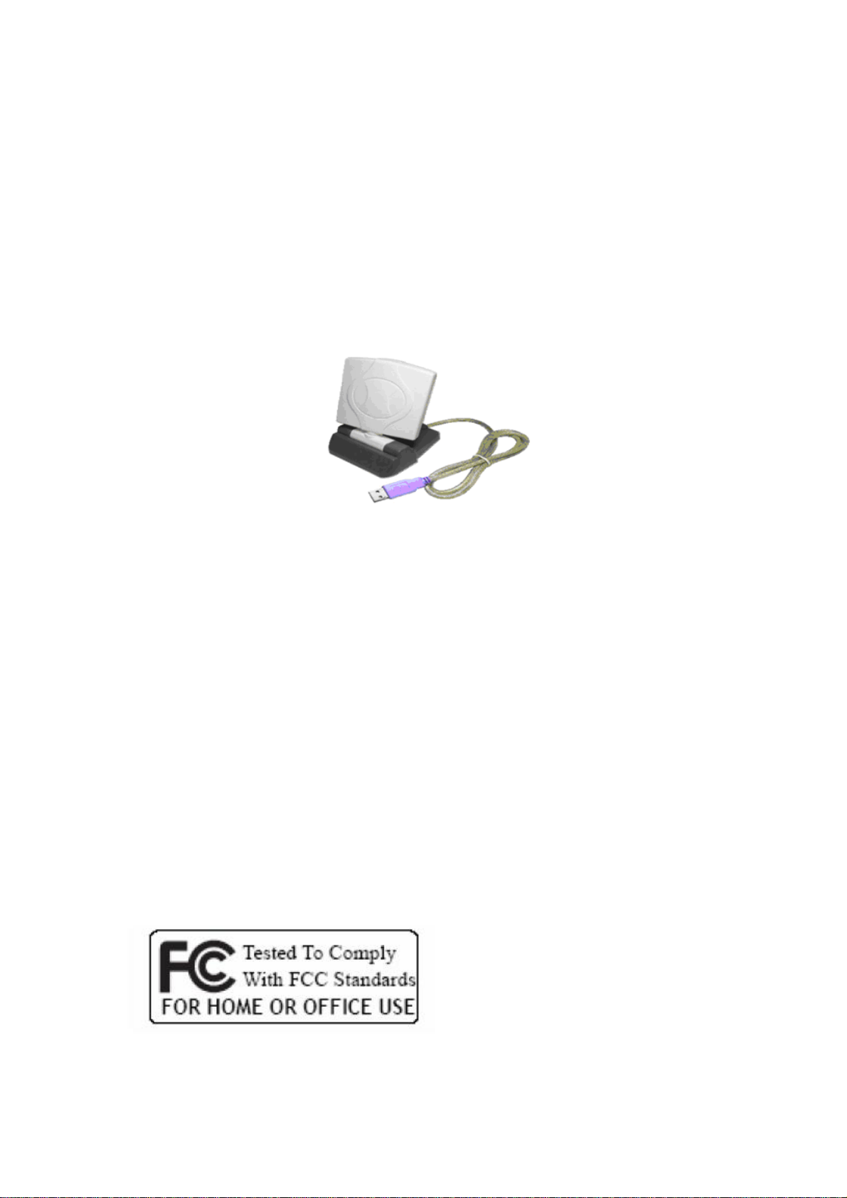
Wireless USB Adaptor
MODEL: SMART CPE
Smart CPE High Power USB Adaptor
WINDOWS USER GUIDE
Version 1.0
LIMITED WARRANTY
We guarantee that each SMART CPE will be free from physical defects in material and
workmanship under normal use for two (2) years from the date of purchase. If the product
proves defective during this two-year warranty period, call our Technical Support in
order to obtain a Return Authorization Number.
When returning a product, mark the Return Authorization number clearly on the outside
of the package and include a copy of your original proof of purchase.

2
Federal Communication Commission Interference Statement
This equipment has been tested and found to comply with the limits for a Class B
digital device, pursuant to Part 15 of the FCC Rules. These limits are designed
to provide reasonable protection against harmful interference in a residential
installation. This equipment generates uses and can radiate radio frequency
energy and, if not installed and used in accordance with the instructions, may
cause harmful interference to radio communications. However, there is no
guarantee that interference will not occur in a particular installation. If this
equipment does cause harmful interference to radio or television reception, which
can be determined by turning the equipment off and on, the user is encouraged to
try to correct the interference by one of the following measures:
- Reorient or relocate the receiving antenna.
- Increase the separation between the equipment and receiver.
- Connect the equipment into an outlet on a circuit different from that
to which the receiver is connected.
- Consult the dealer or an experienced radio/TV technician for help.
This device complies with Part 15 of the FCC Rules. Operation is subject to the
following two conditions: (1) This device may not cause harmful interference, and
(2) this device must accept any interference received, including interference that
may cause undesired operation.
FCC Caution: Any changes or modifications not expressly approved by the party
responsible for compliance could void the user's authority to operate this
equipment.
IEEE 802.11b or 802.11g operation of this product in the U.S.A. is firmware-limited
to channels 1 through 11.
IMPORTANT NOTE:
FCC Radiation Exposure Statement:
This equipment complies with FCC radiation exposure limits set forth for an
uncontrolled environment. This equipment should be installed and operated with
minimum distance 20cm between the radiator & your body.
This transmitter must not be co-located or operating in conjunction with any other
antenna or transmitter.

3
CHAPTER 1: INTRODUCTION
USB ADAPTOR INTRODUCTION
Thank you for your purchase of the SMART CPE USB Adaptor.
This USB adaptor offers great value whether you are an individual purchasing for use at
home or for use in a business of any size.
USB adaptors are a simple and easy way to add wireless to a computer. The majority of
computers now ship with wireless cards built- in, but users commonly find weak signals.
This weak signal can occur due to several factors. One it may be too far from a wireless
router or access point, most internal wireless cards do not provide significant radio
frequency (RF) gain. Another factor is that almost all built- in cards have the antennas
operating horizontally, where the wireless router or access point has vertically polarized
antennas. This results in significant signal loss. Whatever the resulting cause of the weak
signal is, the SMART CPE Adaptor with its internal 6 dBi antenna will enhance your
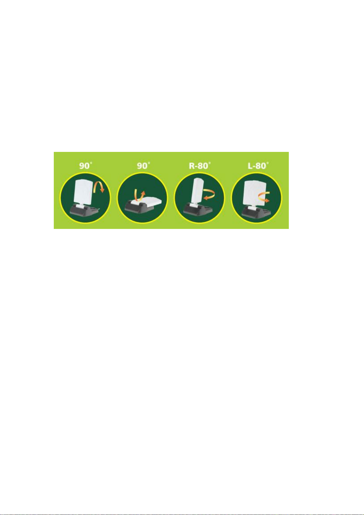
wireless experience. This key to successful wireless experience is adjusted with
flexibility of using different SMART CPE Adaptor antenna’s angle.
The compact design makes it easy for you to travel with the adaptor. It draws its power
from the USB port, so you do not need an external power supply. This adaptor supports
high speed networking up to 54 Mbps per the IEEE 802.11g specification. Of course,
most broadband connections are DSL or cable modems that are limited generally to less
than 6 Mbps, which determines the ultimate throughput rates in accessing the Internet.
As with all USB stick type devices care should be taken while connected to a laptop.
FEATURES
• Compact Size
• High gain 6 dBi Directional Antenna H-Plane & E-Plane: 80 Degree
• USB 1.1 and 2.0 Compliant
• Modulation Method:
IEEE 802.11b: DSS (Direct Sequence Spread Spectrum)
IEEE 802.11g: OFDM (Ortho Frequency Division Multiplexing)
• Supports Microsoft Windows 98SE, Me, 2000, XP, XP x64, Vista (x32 and x64)
• Easy Setup and Operation
• Powered by Host Computer
• Basic to Superior Security Encryption: 64‐bit, 128‐bit or 256‐bit WEP; WPA and W
PA2
• 54/48/36/24/18/12/11/9/6/5.5/1 Mbps Selectable Data Rate
• Supports WMM™ (Wi‐Fi Multimedia) Function
• 2400 to 2485 MHz unlicensed ISM Frequency Band
• 2‐Year Limited Warranty
SYSTEM REQUIREMENTS
• Windows System: Windows 98SE, Me, 2000, XP, XP (x32 and x64), Vista (x32 and
x64)
• PCs must have a device driver installed to allow communication with the USB adaptor.
4
PACKAGE CONTENTS
• USB Adaptor
• CD (Driver/Utility/User’s Manual)
CHAPTER 2: NETWORK PLANNING AND ARCHITECTURE
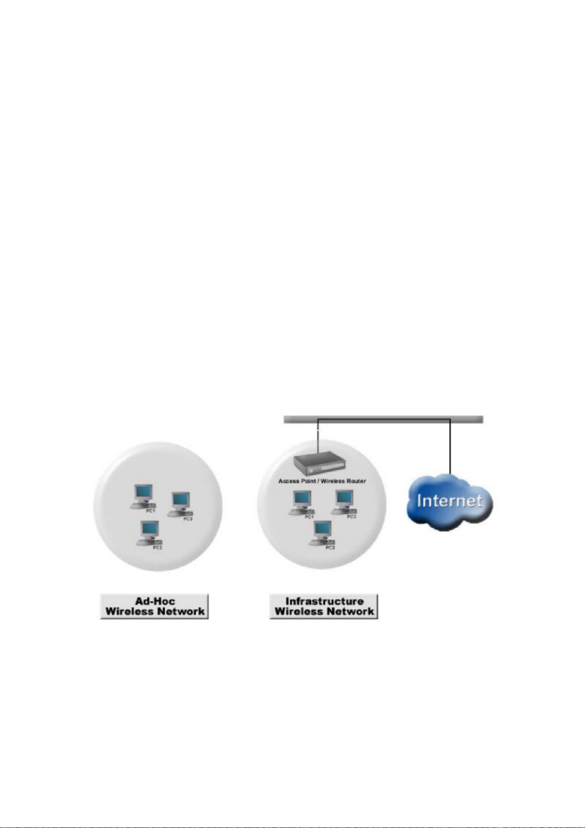
AD‐HOC VERSUS INFRASTRUCTURE MODE
Wireless local area networks (WLAN), as specified in the IEEE 802.11b/g standards have
two different configuration modes:
• Ad‐Hoc
• Infrastructure
Ad‐Hoc is a group of computers equipped with either WLAN cards or wireless USB ad
apters. The group of computers is called a Basic Service Set (BSS). They communicate w
ith each other eliminating the need for an access point or router device. Computers in Ad‐
Hoc mode cannot communicate with computers on a wired network or connect to the Inte
rnet. In our configuration software it is referred to as, “AP mode”. However this does not
imply that it is an access point in the normal sense. Ad‐Hoc is shown in the diagram on th
e left side below.
Infrastructure is where a computer or other network device equipped with the WLAN
card or USB adapter communicates directly with an access point or wireless router.
Infrastructure mode is the normal mode of use for most users. It is referred to as, “station
mode” in our configuration software. An infrastructure example is shown in the diagram
on the right above.
5
ANTENNA
The SMART CPE Adaptor with internal 6 dBi direction antenna. This antenna radiates
radio frequency (RF) in 80 degrees. Users may depending on their access point or
wireless router to adjust correct angle on the antenna to enhance their wireless.
APPLICATIONS
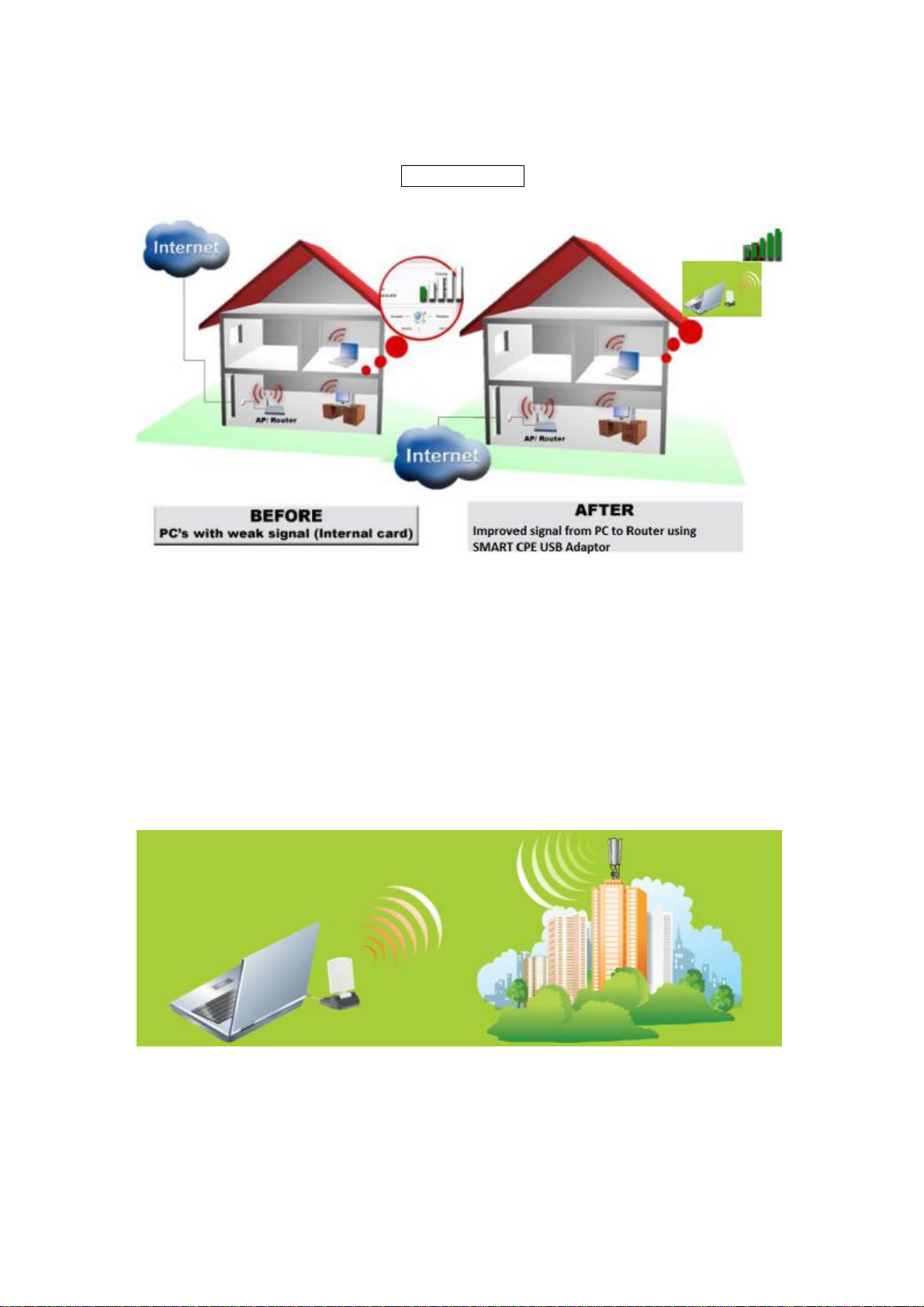
Residential Network – Computer to Router Connectivity
• Residential users commonly do not receive adequate signal coverage throughout their
home. It is often assumed that replacing the existing router antenna for a model with
higher gain will resolve the issue. While in some circumstances this may help, often
the problem is that the internal wireless card in the computer produces to weak of a
signal to reach the router. Installing the SMART CPE device will normally
significantly improve this scenario.
6
HOME Network
Municipal Network Connectivity
• Municipal or city wide network are becoming commonly available. However, users
often have weak or non‐existent signal levels. The connectivity can be greatly
enhanced through the use of the SMART CPE wireless adaptor.
•Whether lounging at the pool or sitting in a local park or in your home, the USB
adapter with an internal direction antenna is the key to improved experience.
7
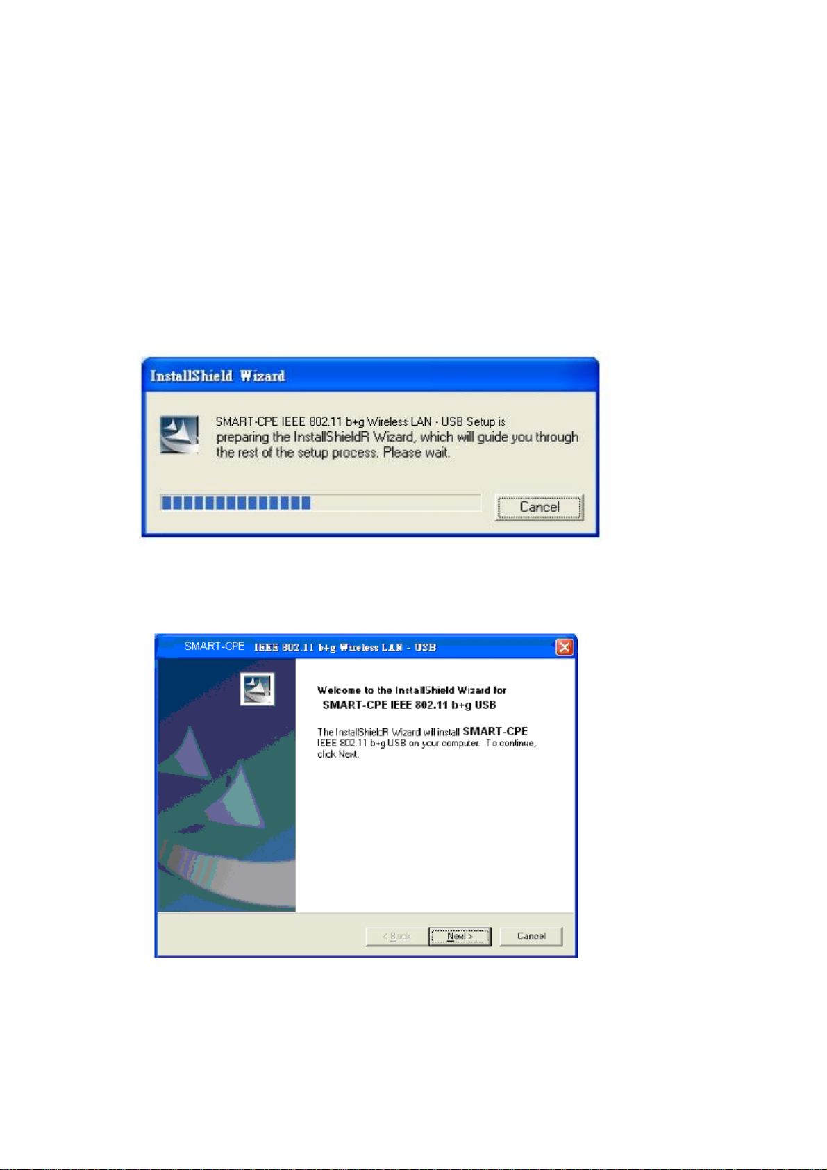
CHAPTER 3: INSTALL DRIVER (Win 98, 2000, XP)
The installation & driver CD will automatically activate the autorun
installation program after you insert the disk into your CD drive.
Step 1:
Insert the installation & driver CD into your CD-ROM drive.
Step 2:
Click Next to continue.

8
Step 3:
Click Next to install at the designated folder.
Or, click “Browse” to select a folder.
9
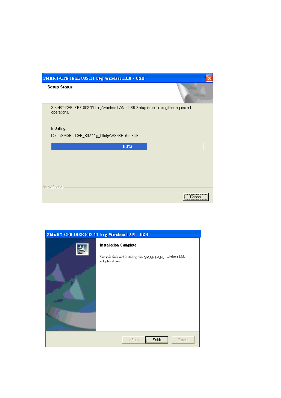
Step 4:
Start copying files until the installation is finished.
Step 5:
Click Finish to complete installation
.
10
Step 6:
After finishing installing the driver and utility on your system, plug the USB
adapter into the USB port of your PC. Windows XP/2000 will automatically
detect the USB Adapter.
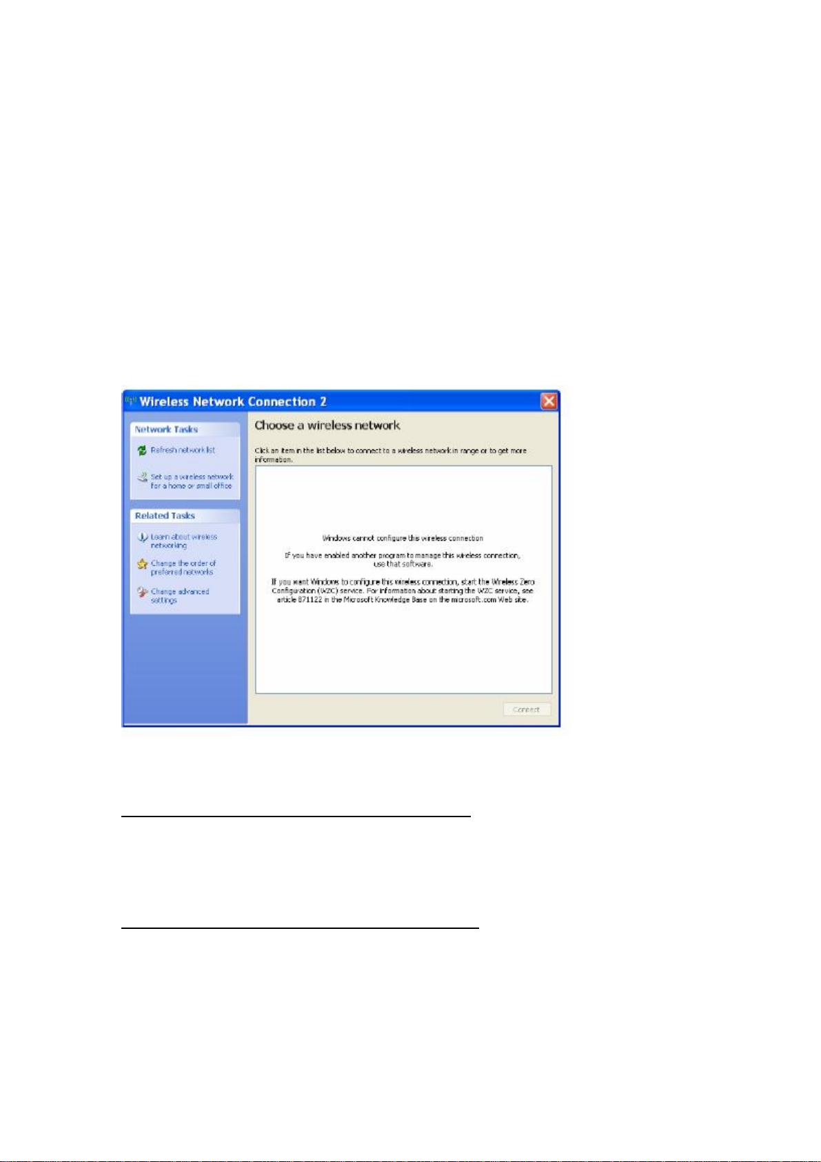
Notes On Windows Zero Configuration Service
Microsoft Windows XP includes the Zero Configuration Service which is used to configure your
wireless client. After clicking on the computer icon on Windows bar in the lower right hand
corner of your screen, you may encounter the following screen. If you have this screen, Windows
Zero Configuration Service is managing your wireless connection and not the Client Utility.
The client manager for the USB adapter and Windows Wireless Zero Configuration Service will
not operate together. You may select to use the Windows Zero Configuration Service (if using
your existing internal wireless card) or the Client Utility (for the USB adapter).
Enable Windows Wireless Zero Configuration Service
Click Start >> Control Panel >> Administrative Tools >> Services to open the Services
configuration window. Select Automatic in the Startup Type field of Wireless Zero Configuration
Service to enable the Wireless Zero Configuration Service and click apply. The default Startup
Type value of Wireless Zero Configuration Service is Automatic.
Disabling Windows Wireless Zero Configuration Service
Click Start >> Control Panel >> Administrative Tools >> Services to open the Services
configuration window. Select Disabled in the Startup Type field of Wireless Zero Configuration
Service to disable the Wireless Zero Configuration Service and click apply.
11
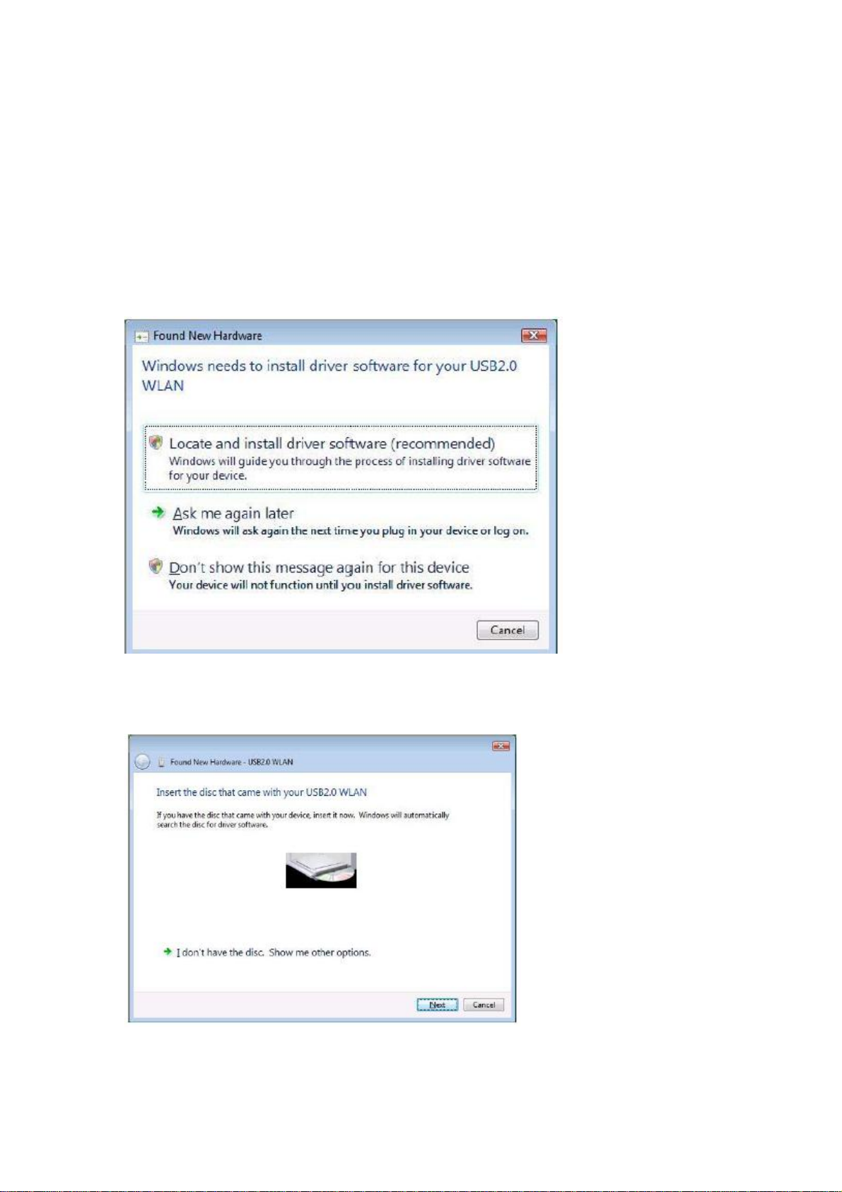
CHAPTER 4: INSTALL DRIVER (Windows Vista)
Plug your USB dongle into USB interface, windows Vista will search for compatible driver to
install.
Step 1:
Select “Locate and install the driver software”, Windows will guide you through the process of
installing driver software for your device.
Step 2:
Insert the installation disc into the CD-ROM and click “next” to continue installation.
 Loading...