

Page 1
Quick Installation Guide
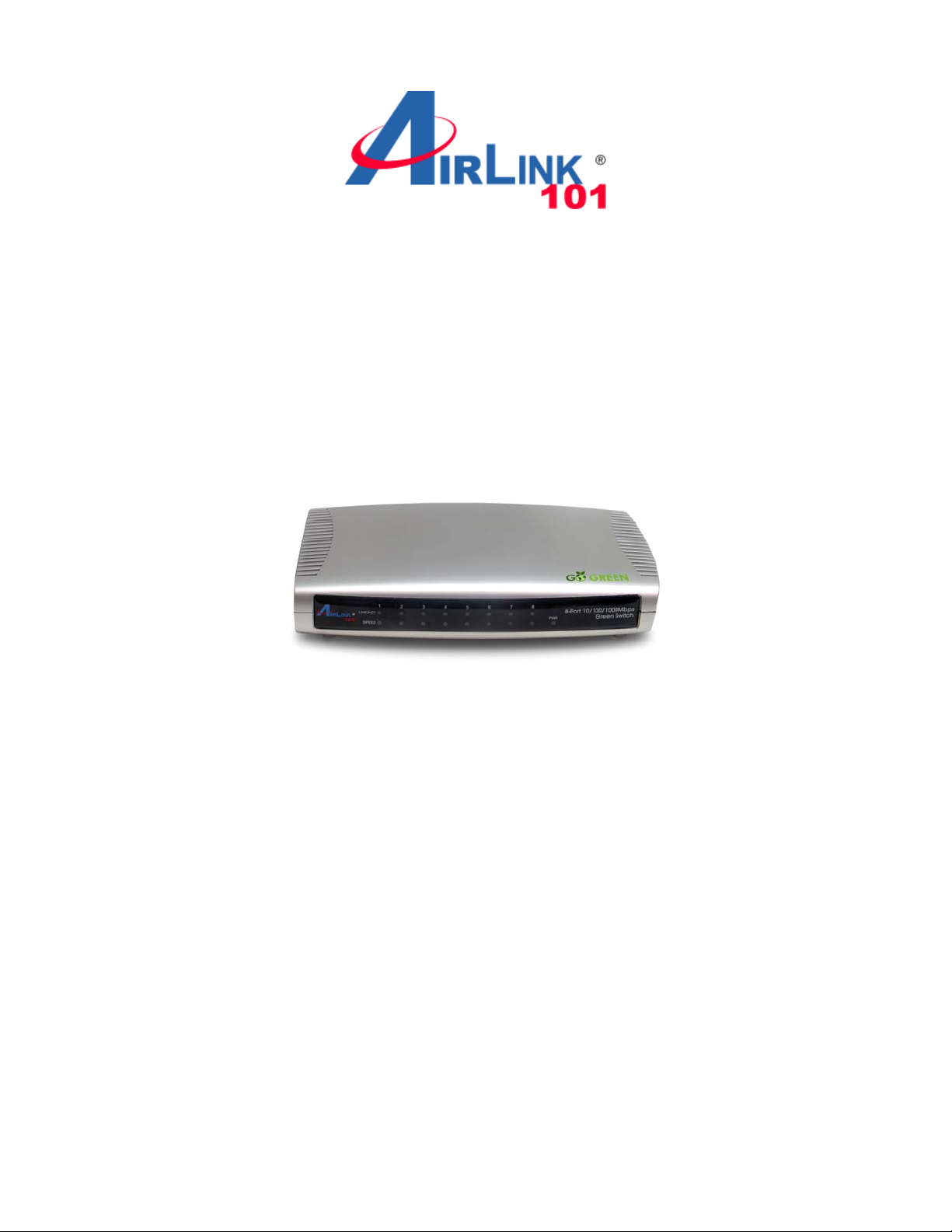
8-Port 10/100/1000Mbps
Green Switch
Model# AGSW801
Ver. 1A
Page 2

Introduction
This Quick Installation Guide tells you how to install your 8-Port
10/100/1000Mbps Green Switch, and how to connect it to your Gigabit
Ethernet network.
The 8-Port 10/100/1000Mbps Green Switch is designe d for energy saving,
easy installation and high performance in an environm ent where network
traffic and the number of users increase continuously. You can add other
Ethernet devices like computers, IP cameras, and Network Attached
Storage (NAS) onto your network quickly and easily. The Green Ethernet
technology of AGSW801 automatically reduces the power usage when a
connected port is detected inactive (idle or cable-unplugged) and
intelligently allocates less power for a port that connects with an Ethernet
cable shorter than 20m (66 ft)*.
Before you begin the installation, please check the items of your package:
Package Contents:
• 8-Port 10/100/1000Mbps Green Switch
• Power Adapter
• Quick Installation Guide
Section 1
Front Panel
Hardware Description
Page 3

LED Indicators
LED Color Status Description
On The switch is powered on.
PWR Green
Off The switch is powered off.
On LAN port is connected.
LNK/ACT Green
Green/
SPEED
Yellow
Off LAN port is not connected.
Flashing Transferring or receiving data.
Yellow On The LAN port is running at 1000Mbps.
Green On The LAN port is running at 100Mbps.
Off The LAN port is running at 10Mbps.
Rear Panel
Ports
Item Name Description
Power Power connector, DC 12V / 1A.
1 - 8 10/100/1000Mbps LAN ports 1 to 8.
Page 4

Section 2
Connecting the Switch
Note: Operating Environment
This switch must be installed and operated within the limits of specified
operating temperature (32~1310F) and humidity (10~90%
Non-condensing). Do not place objects on top of the unit. Do not obstruct
any vents at the sides of the unit. Do not position the unit near any
heating source such as heater, radiator, or direct exposure to sun.
Prevent entering of water and moisture into the unit. If necessary, use
dehumidifier to reduce humidity.
Step 1 Connecting to network devices
The RJ-45 ports on the switch support Auto-MDI/MDI-X function which
allows using straight-through or cross-over type cables to connect this
switch to workstation or hub.
Connect one end of the network cable to the RJ-45 port on the rear panel,
and connect the other end of the network cable to the RJ-45 port on the
network device. Follow the same procedure to connect all the RJ-45 ports
of the switch. The UTP network cables must be four pairs Category 5 or
above for 1000Mbps data transmission; two pairs Category 5 for
100Mbps data transmission; two pairs Category 3, 4 or 5 standards for
10Mbps data transmission. Maximum length, using UTP cable, between
the switch and connected device is 100 meters (300ft). Once the network
cable is connected to both ends and the attached network device is
powered on, the green LNK/ACT LED should be lit.
Step 2 Connecting the power
Connect the output end of the power adapter to the power connector on
the rear panel of the switch. Connect the power adapter to the power
outlet. The green Power LED on the front panel should be lit.
Page 5

Section 3
Troubleshooting
1. Power LED is not lit
• Check if the power adapter is properly connected to the power outlet.
Make sure the power jack is firmly plugged into the power socket of
the switch.
2. Link/Activity is not lit when connect to 10/100/1000Mbps device
• Check the power switch of the network device attached to the switch;
make sure it is turned ON.
• Check the network cable; make sure it is properly connected to the
switch and the network device.
• Check the network cable; make sure the UTP cables comply with the
specifications described in Section 2.
Page 6

Section 4
Technical Support
E-mail: support@airlink101.com
Toll Free: 1-888-746-3238
Website: www.airlink101.com
*Power savings may vary depending on products used. Actual data throughput will vary.
Network conditions and environmental factors lower actual data throughput rate.
Specifications are subject to change without notice. All rights reserved. Copyright © 2009
AirLink101®. AirLink101®, the stylized AirLink101® logo, specific product designations, and
all other words and logos that are identified as trademarks and/or service marks are, unless
noted otherwise, the trademarks and service marks of AirLink101®. All other product or
service names are the property of their respective holders. AirLink101® products are
protected under numerous U.S. and foreign patents and pending applications, mask work
rights, and copyrights.
 Loading...