

Page 1

Host RJ-11 IP Gateway
User Guide
Copyright © 1993-2007 AirLink Communications, Inc. All rights reserved.
Version 1.02 - February 2007
Page 2

Contents
Introduction . . . . . . . . . . . . . . . . . . . . . . . . . . . . . . . . . . . . . . . . . . . 3
Host RJ-11 IP Gateway Features 4
Installation . . . . . . . . . . . . . . . . . . . . . . . . . . . . . . . . . . . . . . . . . . . 5
Before You Start 5
Software Requir ed 5
Hardwar e Required 5
Cellular Account Required 6
Important Information about Ports 6
Configuring your Raven-E for the Host RJ-11 IP Gateway 6
Default settings 6
Configuring the Raven-E 7
Configuring the Intial IP Address for the Host RJ-11 IP Gateway without a Raven-E 9
Configuring the IP Address and Interface Port of the Host RJ-11 IP Gateway 12
Host RJ-11 IP Gateway Defaults 12
Configuring the Host RJ-11 IP Gateway 12
Hardware . . . . . . . . . . . . . . . . . . . . . . . . . . . . . . . . . . . . . . . . . . . 16
Connectors and Reset button 16
Status LEDs 16
Configuration Settings and Commands . . . . . . . . . . . . . . . . . . . . . 19
Web-based Interface 19
Service Configuration 20
Welcome 20
Serial Settings 21
Port Services 22
Phone Number Translation 23
Network Translation 24
Protocol Settings 25
Network Configuration 25
Network Settings 25
DNS Settings 27
IP Routing 28
Time Settings 28
Security Settings 29
Online Update 31
Status and Logs 32
Troubleshooting 32
Host RJ-11 IP Gateway User Guide, version ii
Page 3

Contents
System Log 33
Port Status 33
OS and Network Information 34
Log Files and Settings 35
Commands 36
Ping 36
Reset/Reboot 37
Specifications 38
Physical Dimensions 38
Connections 38
Phone and Modem standards 38
Environmental 38
Optional Mounting Bracket 39
AT Commands 40
Response Codes 42
Modem Signal Behavior 43
Phone Numbers 43
Port Settings 44
Warranty Terms and Conditions 45
Standard Software Warranty 45
One Year Standard Equipment Warranty 45
Remedy 45
WARRANTY DISCLAIMER 46
LIMITATION OF LIABILITY 46
General Conditions 46
AirLink Technical Support 48
AirLink Support Web Site 48
AirLink Documentation and Guides 48
Contacting Technical Support 48
Host RJ-11 IP Gateway User Guide, version iii
Page 4
CHAPTER 1 Introduction
Many existing meters, data loggers, RTU's, PLC's, point-of-sale, and other remote devices only
have physical interfaces designed to access the telephone network. They do not have serial or
Ethernet ports. They currently use analog cellular or standard phone lines to connect in circuitswitched mode for data transfer.
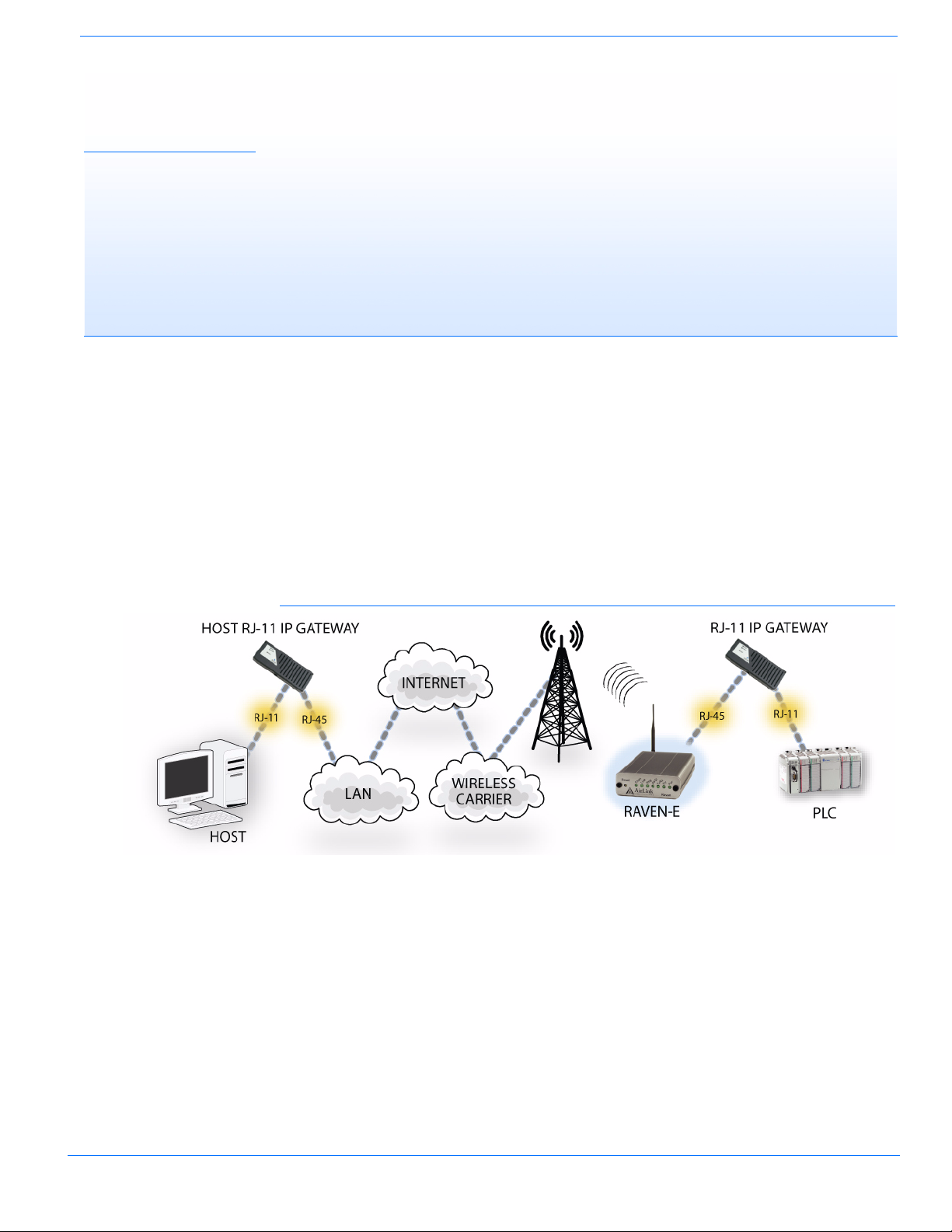
Analog cellular phone service is being discontinued. The combination of the Host RJ-11 IP Gateway, RJ-11 IP Gateway, and the AirLink Raven-E enables remote connectivity between host applications and these remote devices over cellular packet data networks. The RJ-11 IP Gateway
provides the bridge between a device requiring an RJ-11 interface and the Raven-E, with its Ether
net interface. The Host RJ-11 IP Gateway can provide Ethernet-based Internet connectivity to a
Legacy Host system with only RJ-11 ports.
FIGURE 1. Host RJ-11 Ethernet Connectivity for a Legacy Host
-
Host RJ-11 IP Gateway User Guide, version 3
Page 5
Introduction
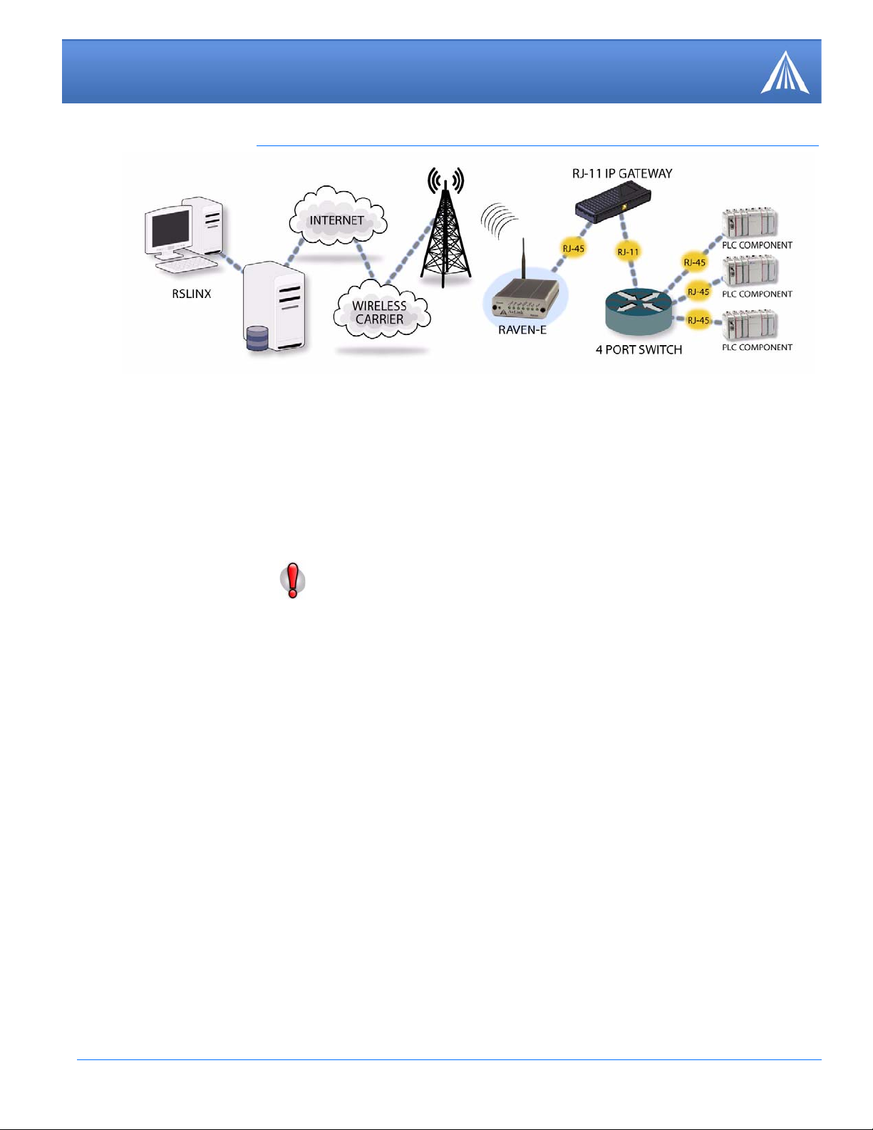
FIGURE 2. Host RJ-11 Gateway with an AirLink Raven-E and a Modem Router
Host RJ-11 IP Gateway Features
• One RJ-11 phone port
The phone port is a phone line designed to function just like standard wall-jack analog phone
line. It is designed primarily to connect dial-up devices, with internal modems, to the RJ-11 IP
Gateway, which then routes data from the devices over the network. The RJ- 1 1 IP Gat eway and
Host RJ-11 IP Gateway mimics the phone company, answering incoming calls and routing
them to an internal modem attached to the phone port, or generating calls from an internal
modem to an attached device.
Caution: The Host RJ-11 IP Gateway's RJ-11 phone port should never be con-
nected into the Public Switched Telephone Network (PSTN). This device is
designed to emulate the PSTN for other devices. The Host RJ-11 IP Gateway may
sustain damage not covered by warranty if it is connected to the Public Switched
Telephone Net work.
• One RJ-45 auto-sensing 10base-T Ethernet port
The Ethernet port is designed to be connected to either an AirLink modem with an Ethernet port
such as the Raven-E or Raven X or any Ethernet-based network. With the modem connected to
the cellular network, the communication from the device connected to the RJ-11 port can be
routed to the Internet and your remote host.
• One power connector
The Host RJ-11 IP Gateway uses a AC power adapter with an optional DC adapter available.
• Status LEDs
The Host RJ-11 IP Gateway status LEDs give clear and concise information about the operation
of the ports.
Host RJ-11 IP Gateway User Guide, version 4
Page 6

CHAPTER 2 Installation
Configuring the Host RJ-11 IP Gateway to work with your network or Raven-E and your RJ-11
equipped device is easy. This chapter covers a basic configuration.
Caution: The Host RJ-11 IP Gateway’s RJ-11 port (labeled “Phone”) should not be
connected into the Public Switched T elephone Network. This port is the emulation
for a Phone that you would have been using with your device. The RJ-11 IP Gate
way will sustain damage not covered by warranty if it is connected to the Public
Switched Telephone Network.
Before You Start
-
Caution: If the Host RJ-11 IP Gateway and Raven-E (as applicable) are going to be
on a hub which is connected to a local network, you will need to be sure the
addresses you select are not used by any other device on the network. Consult with
your network administrator if you are unsure.
Software Required
• Wireless Ace - Graphical interface for configuring your Raven-E. Wireless Ace is located on
Host RJ-11 IP Gateway CD or you can download Wireless Ace from the AirLink website: http:/
/www.airlink.com/support/modems/utilities/. A default installation of this utility is assumed
later in these directions.
If you will not be connecting the Host RJ-11 IP Gateway to a Raven-E, you will not need Wire-
less Ace.
• Host RJ-11 IP Gateway Port Utility - Utility to establish an initial IP address for your Host
RJ-11 IP Gateway. The port utility is located on the Host RJ-11 IP Gateway CD or you can
download it from the AirLink website: ht tp://www.airlink.com/support/modems/rj-11-host.asp.
A default installation of this utility is assumed later in these directions.
If you will be connecting the Host RJ-11 IP Gateway to a Raven-E, you will not need the port
utility. If you can use the default IP address of the Host RJ-11 IP Gateway for the initial config
uration, you, also, will not need the port utility.
Hardware Required
• Ethernet Cable - A cross-over or straight through Ethernet cable.
-
Host RJ-11 IP Gateway User Guide, version 5
Page 7

Installation
If you will be connecting the Host RJ-11 IP Gateway to a Raven-E, you will need a cross-over
Ethernet cable to configure your Raven-E unless your computer’s Ethernet port is auto-sensing.
The Host RJ-11 IP Gateway has an auto-sensing Ethernet port, you can use either a cross-over
cable or a straight-through Ethernet cable to connect the Host RJ-11 IP Gateway to the Raven-E
or your computer.
• Power supplies and a power source - Y ou will need a power supply and power source for both
the Host RJ-11 IP Gateway and the Raven-E (as applicable).
• PC or Laptop - To configure both the Host RJ-11 IP Gateway and the modem (as applicable),
you will need a computer with Internet Access, other than the cellular account, and an available
Ethernet port.
Cellular Account Required
• Cellular Account - If you will be connecting the Host RJ-11 IP Gateway to a Raven-E, you
need to already have an active account with a cellular provider and to have activated your
modem with that provider. The AirLink Raven-E is certified to work with a variety of cellular
providers.
If you need to activate your modem, you can use the Setup Wizard for your cellular provider
which you can obtain from the AirLink website: http://www.airlink.com/support/.
Important Information about Ports
• Port Blocking - Many cellular providers and other ISPs block ports below 1024 which are the
default ports for many server protocols (such as HTTP, telnet, and SSH). If your provider
blocks these ports, you will need to configure a port you can access.
Configuring your Raven-E for the Host RJ-11 IP Gateway
These steps are just a basic configuration to get you started and allow the Raven-E to connect with
the Host RJ-11 IP Gateway . Refer to the modem user guide for more configuration options for spe
cific environments.
Omit this section if you are not connecting your Host RJ-11 IP Gateway to a
Raven-E.
Default settings
• Management Interface IP Address: 192.168.13.31.
• Telnet and Wireless Ace password: 12345
• DHCP server: enabled.
• Public Mode - the IP Address assigned by the carrier is assigned to the Host RJ-11 IP Gateway.
-
Note: If you are intending to use the Host RJ-11 IP Gateway default IP Address of
192.168.1.3, you will need to change the default configuration of the Raven-E.
Host RJ-11 IP Gateway User Guide, version 6
Page 8
Installation
0 - Use Public IP
Configuring the Raven-E
1.
2.
Connect your Raven-E directly to the Ethernet port on your computer and to power.
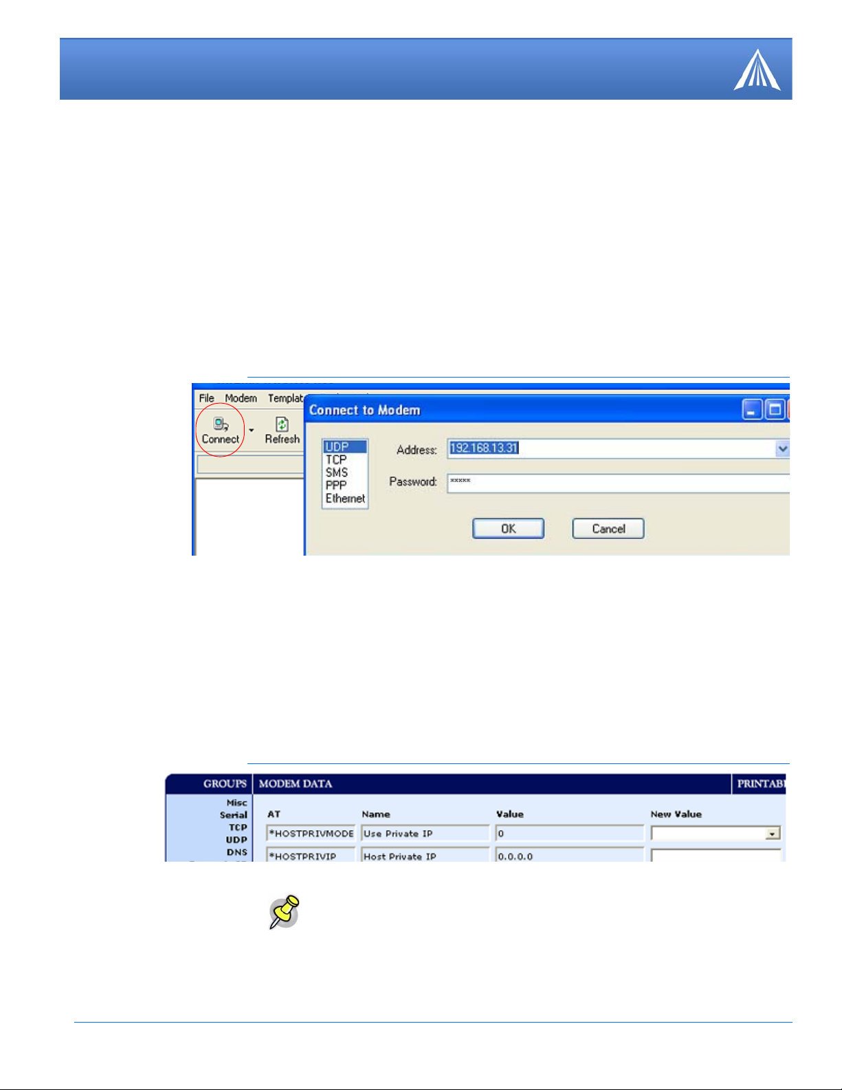
Start Wireless Ace and connect to your modem.
Start > All Programs > AirLink Communications > Wireless Ace 3G > Wireless Ace 3G
A. Click on Connect.
B. Select UDP.
C. Type in the modem’s local IP (default is 192.168.13.31).
D. Type in the modem’s password (default 12345)
FIGURE 1. Wireless Ace: Connect
3.
Select PPP/Ethernet from the menu on the left side of Wireless Ace (under “Groups”).
Public Mode
Configure the Raven-E for Public Mode. Set the *HOSTPRIVMODE to 0. In this mode, the
modem assigns the Host RJ-11 IP Gateway the IP address it has received from your cellular pro
vider. This is the default setting for the modem.
FIGURE 2. Wireless Ace: PPP/Ethernet
Note: The Host RJ-11 IP Gateway is set to a default static IP address of
192.168.1.3, if you want to keep that IP address for the Host RJ-11 IP Gateway,
use Public Mode to set the static IP address for the modem and gateway..
-
Host RJ-11 IP Gateway User Guide, version 7
Page 9

Installation
1 - Use Private IP
192.168.1.4
192.168.1.3
255.255.255.0
Private Mode
Configure the Raven-E for Private Mode. In this mode, the modem communicates with the Host
RJ-11 IP Gateway via a static local IP address.
If the modem and the Host RJ-11 IP Gateway are going to be on a LAN with other
computers and devices you may want to use Private Mode. On a LAN, a DHCP
server other than the modem may give the Host RJ-11 IP Gateway an IP address to
which the modem would not know to send its messages.
a. Set the *HOSTPRIVMODE to 1.
b. Set the *HOSTPRIVIP to the IP address for the Host RJ-11 IP Gateway (in the example,
192.168.1.4).
c. Verify the *HOSTPEERIP is the local IP of the modem. Set this to 192.168.1.3 if you are keep-
ing the default IP address for the Host RJ-11 IP Gateway.
d. Set the *HOSTNETMASK to the Subnet Mask (generally 255.255.255.0).
FIGURE 3. Wireless Ace: PPP/Ethernet
4.
When you have finished configuring the Ethernet settings, click the Write button on the tool bar
of Wireless Ace and wait for the message “Write Successful” to appear in the status bar.
FIGURE 4. Wireless Ace: Write
Note the IP address given to the modem by your cellular provider.
5.
A. Select Status from the menu on the left side of Wireless Ace (under “Groups”).
Host RJ-11 IP Gateway User Guide, version 8
Page 10
Installation
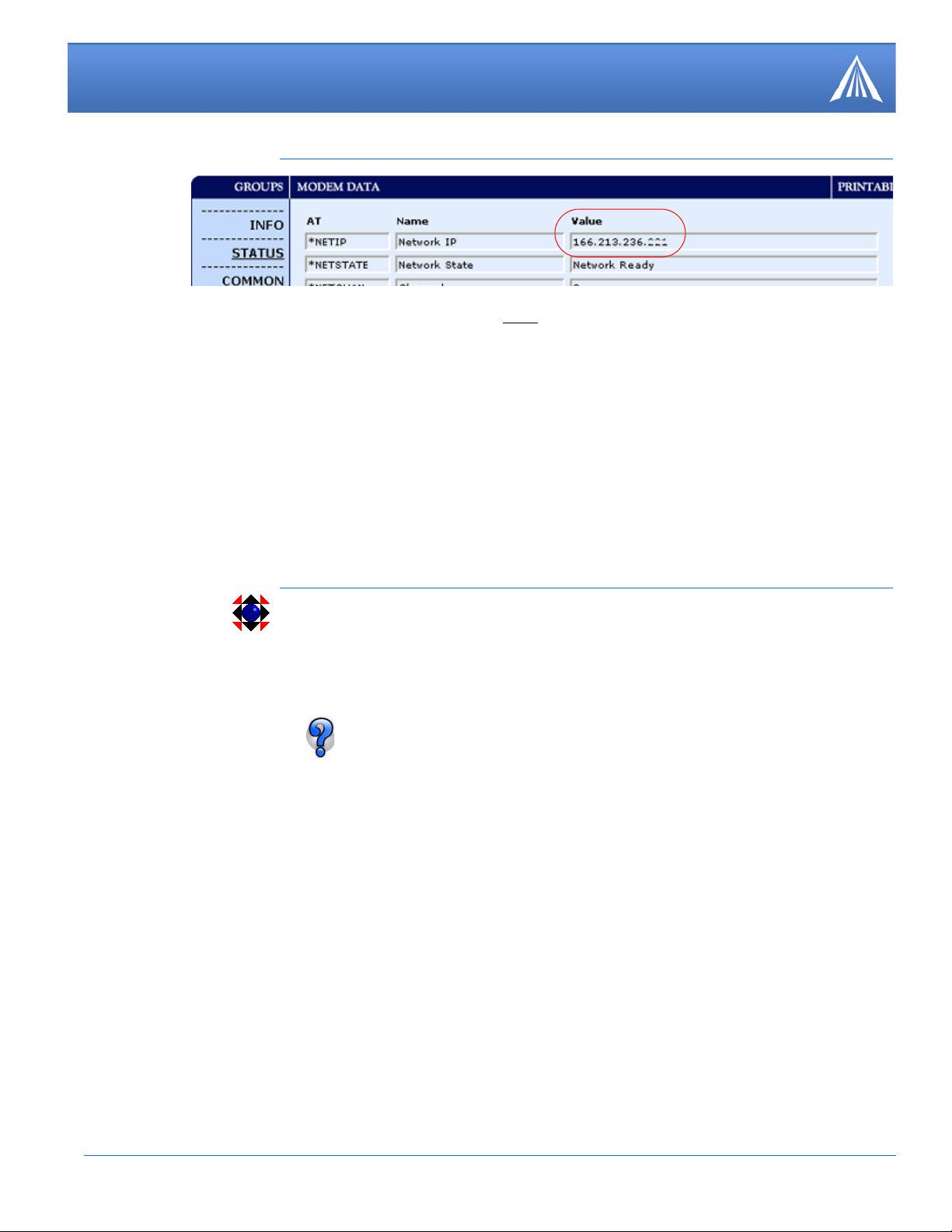
FIGURE 5. Wireless Ace: Status
B. Note the IP address listed in the Value column for the com m a nd *NETIP.
For *NETSTATE, “Network Ready” means your modem is connected on the cellular network and
waiting for connections. “Network Dormant” means the modem is connected and waiting for con
nections but the connection has been idle. In either state, the modem is ready for the steps in the
next section.
-
6.
1.
2.
Disconnect your modem’s Ethernet cable from your computer, but leave the modem connected to
power so it remains on the cellular network.
Configuring the Intial IP Address for the Host RJ-11 IP Gateway without a Raven-E
The configuration interface for the Host RJ-11 IP Gateway is web-based, to be able to access the
interface you will need to connect the Host RJ-11 IP Gateway to a computer using Ethernet.
If you are using a Raven-E with the Host RJ-11 IP Gateway , you do not need to use
this utility, skip this section.
If you are able to use the default IP address of the Host RJ-11 IP Gateway, you,
also, do not need to use this utility.
Connect your Host RJ-11 IP Gateway directly to the Ethernet port on your computer and to
power.
Start the Port Utility.
Start > All Programs > Systech Port Server Utilities
The Port Utility should automatically detect the Host RJ-11 IP Gateway. It may take a short while
for the device to be displayed.
Host RJ-11 IP Gateway User Guide, version 9
Page 11
Installation
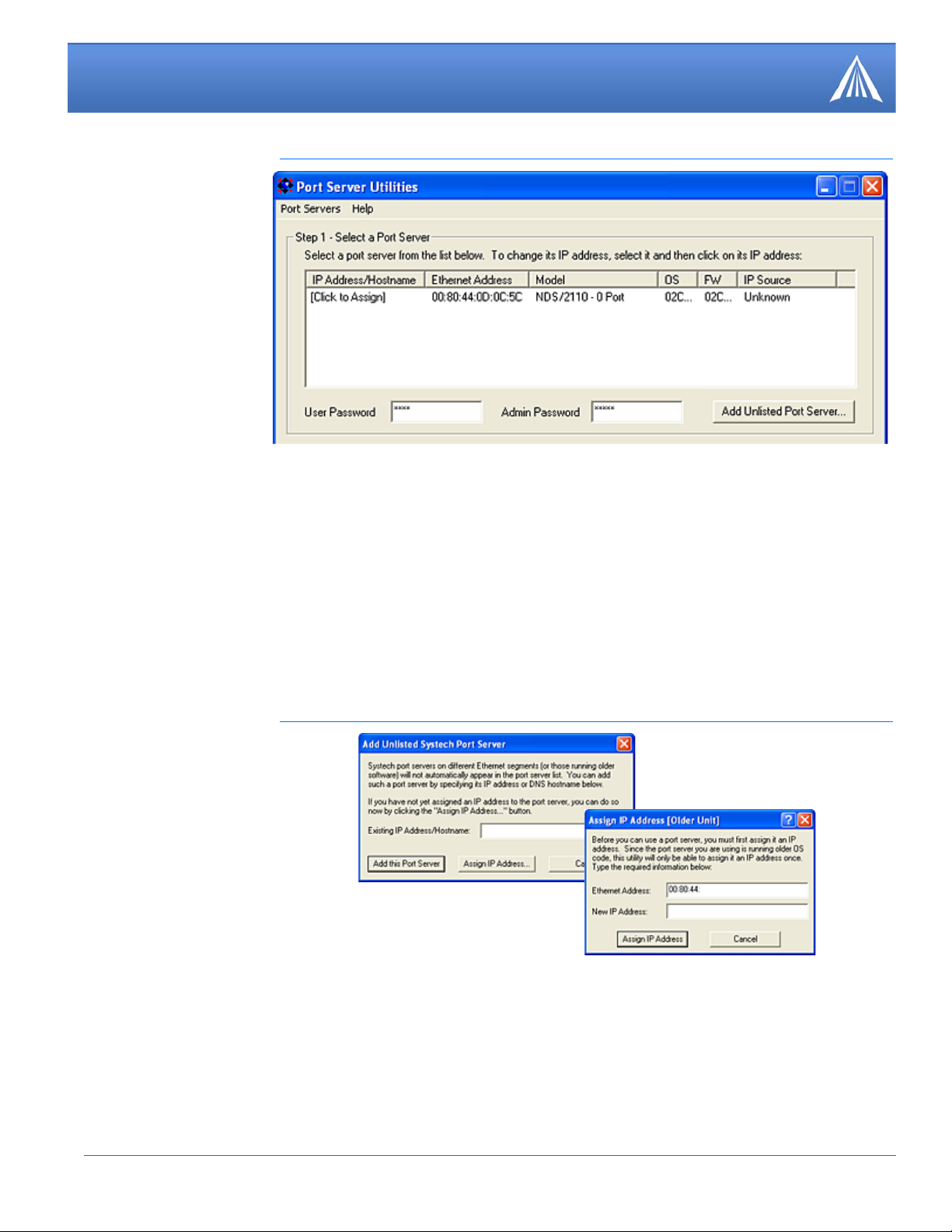
FIGURE 6. Port Utility
3.
optional
Configure a temporary IP address for configuring the Host RJ-11 IP Gateway.
A. Double-click on the [Click to Assign] for the discovered device (if an IP addess is listed in that
column, double-click on the IP address if you need to change it).
B. Type in an IP address. It’s recomended that you use 192.168.1.3.
C. Press Enter to save the address.
If the Host RJ-11 IP Gateway is not displayed in step 2, you will need to manually add the device.
A. Click on Add Unlisted Port Server.
FIGURE 7. Add Unlitsed Port Server
B. Click on Assign IP Address.
C. Enter the MAC address found on a sticker beside the Ethernet port on the Ethernet Address
line.
D. Type in the desired IP Address as noted in step 3 above.
E. Click Assign IP Address.
Host RJ-11 IP Gateway User Guide, version 10
Page 12
Installation
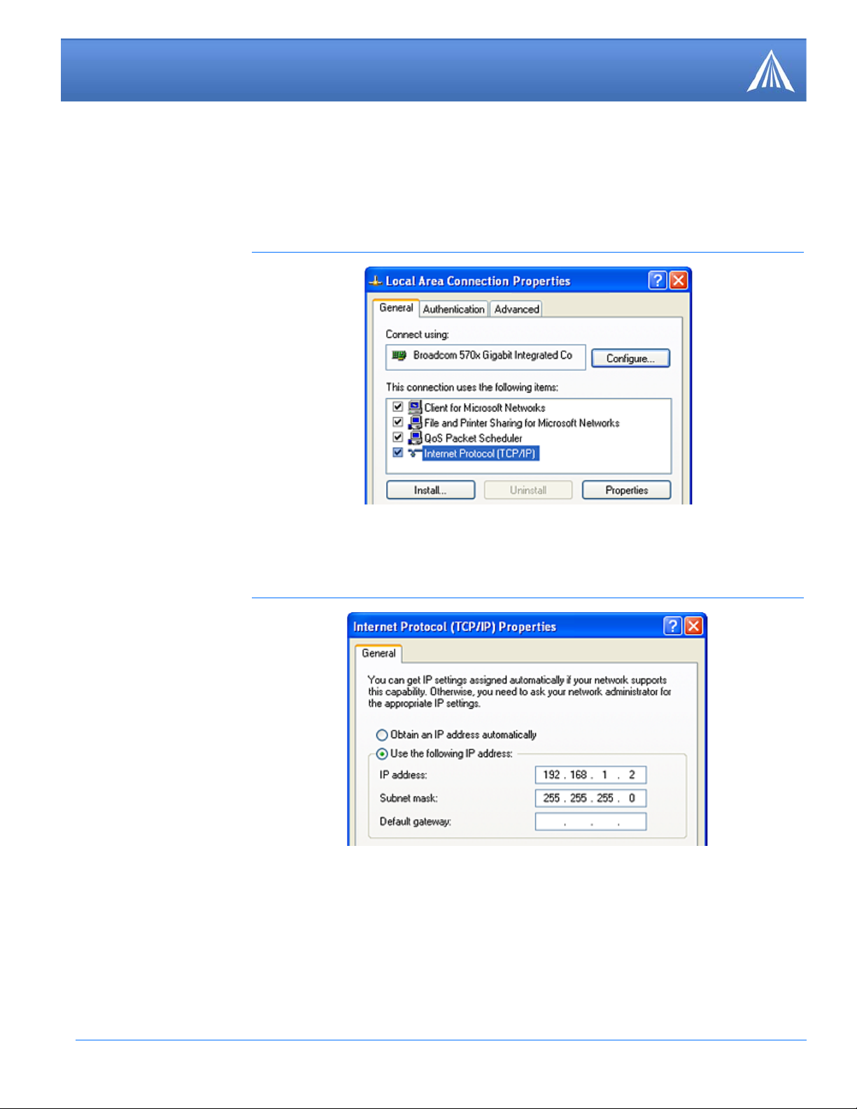
4.
T emporarily change your computer to a static IP address to configure the Host RJ-11 IP Gateway.
A. Open the properties for your network connection. Start>Control Panel>Network Connections,
right-click on your local area connection, and select Properties.
FIGURE 8. Local Area Connection
B. Select Internet Protocol (TCP/IP) and click on Properties.
C. Note the current settings (so you can return to them when you finish).
FIGURE 9. TCP/IP Properties
D. Change the IP address to match the temporary IP address you configured for the Host RJ-11 IP
Gateway. The last number needs to be different. If you configured 192.168.1.3 for the Host
RJ-11 IP Gateway, you should use 192.168.1.2 for your computer.
E. Do not disconnnect your computer from the Host RJ-11 IP Gateway.
F. Follow the directions in the next section. Omit the first step and use the IP address you config-
ured in this section for the IP address instead of one from the Raven-E.
Host RJ-11 IP Gateway User Guide, version 11
Page 13

Installation
http://166.213.236.221:9080
http:192.168.1.3:9080
Note: When you have completed configuring the Host RJ-11 IP Gateway, you will
want to reconfigure the IP address on your computer to how it was configured
before you started these steps. Use the directions in this step to reset the configura
tion.
Configuring the IP Address and Interface Port of the Host RJ11 IP Gateway
Host RJ-11 IP Gateway Defaults
• Phone port: 8 data bits, no parity, and 1 stop bit (8N1).
• Protocol: American/Bell 212A.
• Maximum baud: 2400.
• DHCP client: disabled.
• IP Address: 192.168.1.3.
-
1.
2.
Note: If you are using the defaults for the Host RJ-11 IP Gateway, you can skip this
section and connect your Host RJ-11 IP Gateway directly to your device and net
work.
-
Configuring the Host RJ-11 IP Gateway
Connect the Host RJ-11 IP Gateway to power and connect the Ethernet cable from your computer
to the Host RJ-11 IP Gateway.
Type “http://192.168.1.3:9080” (see the example in the screenshot below) in the Address or
Location bar and press the enter key.
FIGURE 10. Web Browser : Enter the Location
Since many cellular carriers block the standard web browser ports (80 and 8080),
the Host RJ-11 IP Gateway uses 9080 by default as the port for the web-based
interface.
Host RJ-11 IP Gateway User Guide, version 12
The web-based interface will open. On the left side of the window are menu options. The central
area of the window is the working area (shown in the close up screen shots for the configuration
settings).
Page 14
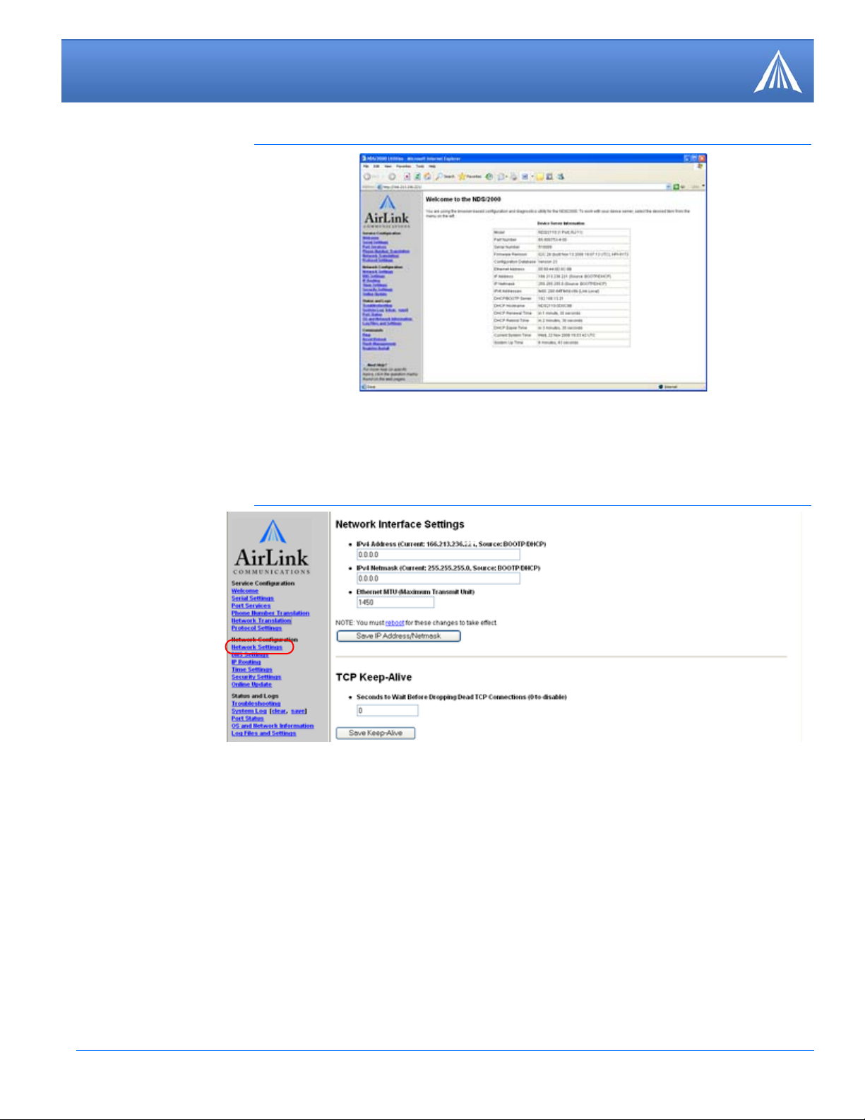
Installation
FIGURE 11. Host RJ-11 IP Gateway Interface
3.
Select Network Settings from the menu on the left.
FIGURE 12. Host RJ-11 IP Gateway: Network Settings
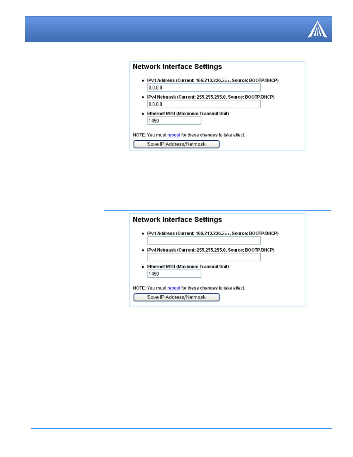
DHCP Mode
In DHCP Mode, the Host RJ-11 IP Gateway will receive its IP address from the modem.
The IPv4 Address and the IPv4 Netmask should be listed as 0.0.0.0.
Host RJ-11 IP Gateway User Guide, version 13
Page 15
Installation
192.168.1.3
255.255.255.0
FIGURE 13. RJ-11 IP Gateway: Network Interface Settings
Static IP Mode
If the Host RJ-11 IP Gateway is going to be on a LAN, you many wish to set a static IP address.
Use this mode only if you have configured Private Mode for the modem. The default for the Host
RJ-11 IP Gateway is a static IP address of 192.168.1.3.
4.
FIGURE 14. Host RJ-11 IP Gateway: Network Interface Settings
A. Set the IPV4 Address to match the *HOSTPRIVIP in step 3 of the previous section.
B. Set the IPV4 Netmask to match the *HOSTNETMASK in step 3 of the previous section.
C. Click the Save IP Address/Netmask button.
Select Serial Settings from the menu on the left.
The Serial Settings page allows you to specify the baud rate, protocol, character size, parity, stop
bits, and flow control behavior for the RJ-11 port (Phone).
Host RJ-11 IP Gateway User Guide, version 14
Page 16

Installation
8None
1
FIGURE 15. Host RJ-1 1 IP Ga tewa y: Serial Settings
For more information on these settings, refer to page 21.
Note: For most configurations, the default settings are best. Change these parame-
ters only if you know the device you will be connecting to the Host RJ-11 IP Gateway requires special settings.
5.
Click on the Reset/Reboot menu option for the IP Address configuration and any changes to the
serial port settings to take effect.
FIGURE 16. Host RJ-11 IP Gateway: Reset/Reboot
Click the Reboot button to restart the Host RJ-11 IP Gateway with the configured settings.
Host RJ-11 IP Gateway User Guide, version 15
Page 17

CHAPTER 3 Hardware
Power
RJ-45 Ethernet
Reset
RJ-11
Designed for simplicity, the Host RJ-11 IP Gateway hardware has few complicated parts.
Connectors and Reset button
The Reset button is recessed. To reset the connection, using an unbent paperclip or other narrow,
blunt tip, press and quickly release the reset button. T o reset the configuration to the factory default,
press and hold the reset button until you see the appropriate alternating light sequence.
FIGURE 1. Right side: RJ-45 connector, Power connector, and Reset button (not to scale)
FIGURE 2. Left side: RJ-11(phone) connector (not to scale)
Caution: The Host RJ-11 IP Gateway's RJ-11 phone port should never be con-
nected into the Public Switched Telephone Network (PSTN). This device is
designed to emulate the PSTN for other devices. The Host RJ-11 IP Gateway may
sustain damage not covered by warranty if it is connected to the Public Switched
Telephone Net work.
Status LEDs
The top panel of the Host RJ-11 IP Gateway displays the status LEDs.
Host RJ-11 IP Gateway User Guide, version 16
Page 18

Hardware
FIGURE 3. Host RJ-11 IP Gateway Top Panel (not to scale)
• STATUS - Indicates the overall status of the device.
TABLE 1. Status - Normal Operation
LED Condition Description
Blinking Yellow The Host RJ-11 IP Gateway is starting up.
Solid Green The Host RJ-11 IP Gate way is obtaini ng an IP address fr om
the modem.
Blinking Green The Host RJ-11 IP Gateway has an IP address and is operat-
ing normally.
Off No power to the Host RJ-11 IP Gateway.
TABLE 2. Status - Resetting the Configuration
LED Condition Description
Alternating Green/Red While the Reset button is held in, the status light will begin
to blink in this sequence to indicate the Host RJ-11 IP Gate
way will shortly restore the factory default condition.
If you do not want to restore the factory default, release the
button before the sequence changes to Green/Yellow.
Alternating Green/Yellow While the Reset button is held in, the status light will begin
to blink in this sequence to indicate the factory default con
figuration was restored. Once the Host RJ-11 IP Gateway
indicates the configuration was restored, you can release the
reset button.
TABLE 3. Status - Error Conditions
-
-
LED Condition Description
Alternating Green/Red A serious system error occurred. See the system log for
more details.
Host RJ-11 IP Gateway User Guide, version 17
Page 19

Hardware
TABLE 3. Status - Error Conditions
Alternating Green/Yellow The current configuration is corrupt and the factory default
configuration is being used
Solid Red The Host RJ-11 IP Gateway has encountered a fatal error,
contact technical support for assistance.
• ETHERNET - Indicates the status of the Ethernet connection (RJ-45 port).
TABLE 4. Ethernet
LED Condition Description
Solid Green The Ethernet link is available and idle.
Green/Yellow Blinking Network traffic is detected.
Off The Ethernet link is unavailable.
• PHONE - Indicates the status of the phone port (RJ-11).
TABLE 5. Phone
LED Condition Description
Solid Green The port is open and idle.
Blinking Green The port is open, and data is being transmitted or received.
When data is being continuously transferred, this LED will
blink approximately 2 times per second.
Blinking Red Data errors will cause periodic red blinks. Persistent red
blinks may imply a configuration problem (incorrect baud
rate, parity settings, etc.)
Yellow Port is closed.
Solid Red Port hardware has failed.
Off Power is off.
Host RJ-11 IP Gateway User Guide, version 18
Page 20

CHAPTER 4 Configuration Settings and
http://166.213.236.221:9080
Commands
The Host RJ-11 IP Gateway can be configured to handle a variety of devices which need to connect
to an RJ-11 port.
If you’re using a Raven-E with the Host RJ-11 IP Gateway, for configuration
options for your Raven-E, refer to the modems’s user guide. All user guides are
available on the AirLink website: http://www.airlink.com/support.
Web-based Interface
Note: Screen shots in this guide are using Microsoft Internet Explorer, but you can
use any web browser to configure the Host RJ-11 IP Gateway.
The Host RJ-11 IP Gateway employs a web-based user interface. To access the web interface, you
will need to know the IP Address given to your Raven-E by the cellular carrier (or the modem
domain name if you have configured IP Manager settings for the modem). Type the IP address (or
modem domain name) into the Address bar of your web browser followed by “:9080” (see the
example below).
Since many cellular carriers block the standard web browser ports (80 and 8080),
the Host RJ-11 IP Gateway uses 9080 by default as a port for the web-based inter
face.
FIGURE 1. Web Browser: Enter the Location
The web interface for the Host RJ-11 IP Gateway, by default, has no security. If you made changes
to the security configuration (
name and password before the web-based interface will open.
“Security Settings” on page 29), you will be prompted for a user
-
Host RJ-11 IP Gateway User Guide, version 19
The menu selections for the configuration interface are on the left side of the window.
Page 21

Configuration Settings and Commands
FIGURE 2. Host RJ-11 IP Gateway Web Browser-based Interface
Service Configuration
Most of the Service Configuration menu options deal with the RJ-11 port.
Welcome
The Welcome screen is the first page displayed when you connect to the Host RJ-11 IP Gateway.
Current settings and status are shown in a table.
FIGURE 3. Host RJ-11 IP Gateway: Welcome - Device Server Information
Host RJ-11 IP Gateway User Guide, version 20
Page 22

Configuration Settings and Commands
• Ethernet Address: MAC Address of the Host RJ-11 IP Gateway.
• IP Address: The current IP Address of the Host RJ-11 IP Gateway and how the IP address was
assigned (in the example, a Raven-E in Public Mode used DHCP to give the Host RJ-11 IP
Gateway the IP addressed assigned by the cellular network).
• IP Netmask: The current subnetmask of the Host RJ-11 IP Gateway and how the device
obtained it.
Serial Settings
The Serial Settings page allows you to specify the baud rate, protocol, character size, parity, stop
bits, and flow control behavior for the RJ-11 port (Phone).
Note: For most configurations, the default settings (shown in the screen shots) are
best. Change these parameters only if you know the device you will be connecting
to the Host RJ-11 IP Gateway requires special settings.
FIGURE 4. Host RJ-11 IP Gateway: Serial Settings
• Enabling flow control enables it on both input and output.
• The inactivity time-out shuts down the service on the port if there is no input or output in the
specified time-out period.
Host RJ-11 IP Gateway User Guide, version 21
Page 23

Configuration Settings and Commands
• With Modem Signal Loopbacks, the Host RJ-11 IP Gateway eliminates the use of specialized
cables required to change signal types and directions by performin g th e loopback of signal
types to other signal types internally.
• NativeCOM, (or any RFC-2217 Telnet client with COM-PORT-OP TION support) overrides the
baud rate, size, parity, stop bits and flow control parameters.
Port Services
By default, the RJ-11 port is configured to accept incoming TCP connections from TCP/telnet clients with outgoing service based on phone numbers dialed by the attached device (Modem Service). You may configure the ports to initiate outgoing raw TCP or telnet connections to remote
servers. In addition, the modem emulation feature may be enabled to allow a serial port to mimic a
modem interface.
• When using the modem service on the port, the phone number will be translated to a host/port
pair then a TCP connection will be established to the remote host.
• When using outgoing connections on the port, the settings configured on the Serial Settings
page will be applied to the port, and a TCP connection will be established to the remote host.
• Once connected, data received on the port is sent to the remote server over the network connec-
tion and data received on the network connection is sent out the port.
FIGURE 5. Host RJ-11 IP Gateway: Port Services
• No Outgoing Service: Disables outgoing port services on the specified port. Incoming connec-
tions are still allowed. All port services options will reset to defaults.
Host RJ-11 IP Gateway User Guide, version 22
Page 24

Configuration Settings and Commands
18005551212
192.168.13.100
5004
Define Protocol
Settings
default.eairlink.com
5003
Settings
Edit Protocol
5551212
*
• Modem Service: Enables modem emulation on both the incoming and outgoing network con-
nections. The target peer (specified in the Phone Number Translation table and configured in
the Protocol Settings page) determines the type of outgoing connection that will be made.
• Outgoing Network Connection: Enables an outgoing connection to the specified host.
• Outgoing Telnet Connection: Enables an outgoing telnet connection to the specified host.
• Modem Service Options: When Modem Service is selected, you may also configure the
Source TCP Port. In most cases, the value used for the source port is arbitrary and you can
leave this field set to 0 for “any”. However, if your server or firewall has specific requirements
you may specify an explicit source port number in the Source TCP Port field. If this port is not
available when the TCP service starts up, an error will occur and the TCP service will reset and
try again.
Phone Number Translation
This table can be used to translate phone numbers into IP addresses or Hostnames. If the attached
device dials one of the specified telephone numbers, the corresponding IP address and port are
used to make the TCP connection. Note that all non-numeric characters except the “,” (comma) in
the phone number are ignored.
When modem emulation is enabled, the Host RJ-11 IP Gateway can detect the phone number from
ATD commands. Although the IP address of the remote host can be embedded directly into the
ATD command, certain devices can't always be easily configured to do this.
FIGURE 6. Host RJ-11 IP Gateway: Phone Number Translation
The Default Translation entry is used if the dialed phone number is not found in the list. (The dial
backup number is not used in the Host RJ-11 IP Gateway.) The phone number table has a number
of features to ease initial configuration. When an attached device dials a number that is not in the
table, the device server creates a dummy entry in the table. This entry will consist of just the phone
number. Until you fill in the remainder of the entry (IP Address/Hostn ame an d Port) and save it,
this entry will not be used.
Host RJ-11 IP Gateway User Guide, version 23
Page 25

Configuration Settings and Commands
Once you have created and saved an entry in the table, a link to the associated entry on the Protocol
Settings page appears on the right. If the protocol is not yet defined, this link, “Define protocol”,
will create a new entry on the Protocol Settings page, otherwise the link will be “Edit protocol”.
The translation table screen allows you to add up to 5 new entries at a time. A total of 64 entries
may be configured including the default entry.
In the example above, if the attached device dials 18005551212, the port will be connected to the
host at 192.168.13.100 on TCP port 5004. This host is not yet defined, so it will use the default
TCP protocol. If the attached device dials any other number, the port will be connected to
default.eairlink.com:5003, whose protocol is defined. And the termin al has actually dialed 5551212, generating an automatic, but not yet saved, entry.
Network Translation
The Host RJ-11 IP Gateway is capable of accepting incoming TCP connections and redirecting
them to remote TCP hosts. This functionality is called network translation and behaves much like a
TCP “pipe” between two systems. The Host RJ-11 IP Gateway also uses Network Translation to
allow connections to the web-base interface on a port other than the http protocol defined port of
80 which is frequently blocked by cellular carriers.
FIGURE 7. Host RJ-11 IP Gateway: Network Translation
It is also possible to modify the network protocol traveling through the TCP pipe by using the Protocol Settings page to define the remote host's protocol requirements. The most common use for
this functionality is to add SSL encryption to an incoming TCP connection prior to sending it along
to the remote host.
The Network Translation table is used to define network mappings for TCP pi pe s. You must f irst
specify the incoming TCP port to which your device or application will connect. Then, you must
specify the outgoing hostname and destination TCP port for the TCP pipe.
You can also specify the source TCP port for the outgoing TCP connection. Usually , this should be
set to 0 to allow automatic selection of the source port. However, if you have a firewall that
Host RJ-11 IP Gateway User Guide, version 24
Page 26

Configuration Settings and Commands
imposes limits on source TCP ports then you may need to set this to something specific. Note that
if you specify something other than 0, you will be limited to only 1 TCP pipe at-a-time for any
given destination port.
Protocol Settings
For each host (peer) you will make an outgoing connection to, you need to specify the protocol
options used for that host. For each host, select the Host from the “Edit settings for a different peer”
selection box. Select “Add a new peer definition” link to add a new host.
FIGURE 8. Host RJ-11 IP Gateway: Protocol Settings
The hosts are identified by their IP address or Hostname and TCP port. You may also specify wild
cards. Specific host names and/or port numbers take precedence over the wild cards. An asterisk
for the IP address/hostname (for instance “*:443”) means any other host when connecting on port
443. An asterisk for the port number (for instance “host.peer.com:*”) refers to any other port on
that host. And a double asterisk (“*:*”) refers to all other hosts.
Network Configuration
The Network Configuration group configures settings for the RJ-45 Ethernet port.
Network Settings
The Network Settings page allows you to set the IP address, the IP netmask, and the TCP keepalive settings.
Every IP address contains two pieces of information: the network number and the host number. A
network number is assigned to each local area network and is shared by all the network devices on
that network. Each network device, or “host”, is assigned a unique host number. The IP netmask
defines which portion of an IP address contains the network number, and which portion contains
the host number. The default netmask depends on the “class” of the IP address that you are using.
Host RJ-11 IP Gateway User Guide, version 25
Page 27

Configuration Settings and Commands
In one type of configuration, the Host RJ-11 IP Gateway has been designed to work in conjunction
with an AirLink Raven-E. The IP address for the Host RJ-11 IP Gateway and the IP address for the
Raven-E need to be on the same network. If you need to set a specific IP address for the Raven-E
and the Host RJ-11 IP Gateway , you will need to use Private Mode for the Raven-E. Setting Private
Mode is covered in the Raven-E User Guide.
FIGURE 9. Host RJ-11 IP Gateway: Network Interface Settings
TCP keep-alive is a standard feature of TCP/IP that can be configured to automatically monitor the
state of TCP connections. If one end of an idle TCP connection is severed (like by a network or
power failure), it is possible for the other end to remain open indefinitely. If a network host fails
while it has an open TCP connection to one of the device server’s serial ports, that serial port might
remain unavailable until it is manually reset.
The optional TCP keep-alive feature sends special “keep-alive” packets to the remote TCP host in
order to detect the situation where the remote host fails. If a failure is detected, the TCP connection
is reset to allow other hosts to access the serial port.
To enable TCP keep-alives on serial-related network connections, enter the total time (in seconds)
that you will allow TCP connections to remain idle before resetting them. The first keep-alive
packet will be sent after the connection has been idle for half of this total time. After that, four
more TCP keep-alive packets will be sent at regular intervals until a TCP response is received from
the remote host. If no response is received before the total keep-alive time runs out, the TCP con
-
nection will be reset.
Caution: Enabling TCP keep-alives will increase the amount of network traffic on
your network. Unless you have a specific need for this feature, it is best to leave it
disabled. If you do enable it, it is best to make the keep-alive time-out larger to
reduce network traffic.
Host RJ-11 IP Gateway User Guide, version 26
Page 28

Configuration Settings and Commands
DNS Settings
The DNS Settings page allows you to specify a DNS name for your unit, specify the addresses of
DNS servers to resolve names, and to pre-define some host names. The DNS name and servers can
also be derived from a DHCP server.
FIGURE 10. Host RJ-11 IP Gateway: DNS Settings
If the device server is configured to use DHCP, it will try to get DNS configuration information
from the DHCP server. You may also manually set up static DNS entries on this page. Having DNS
configured allows you to specify names in place of IP addresses in your configuration.
The DNS Domain Name is used as the default domain for any names you specify. For instance, if
you specify the name “foo” in the ping command and the domain name “company.com” in the
DNS Domain Name above, the ping command will do a DNS lookup on the name “foo.com
pany.com”.
Host RJ-11 IP Gateway User Guide, version 27
-
Page 29

Configuration Settings and Commands
The DNS Server IP Addresses are used to specify the addresses of one or more machines that can
be used to resolve names to IP addresses.
The Static Hosts entries are used to define local host name to IP address mappings.
IP Routing
The IP Routing page lets you configure network routes for accessing remote networks.
FIGURE 11. Host RJ-11 IP Gateway: IP Routing
If the device server is configured to use DHCP, it will try to get IP configuration information from
the DHCP server. You may also manually set up static routes on this page.
Each IP route consists of a destination IP address, a netmask, and a gateway IP address. Depending
on the netmask, the destination IP can specify one of two route types:
• Host route: This is a route to a specific IP host. The netmask is always 255.255.255.255.
• Network route: This is a route to an IP network. The netmask defines which portion of the des-
tination IP address contains the network number.
The current routing table is also displayed on this page for your reference.
Time Settings
The Time Settings page allows you to configure NTP or HTTP time-servers to get the system time
from. If you are using SSL for peer verification, the device server must obtain a valid time from an
external time-server to verify the peer.
Time is used in the system and other logs. Having the correct time can help to troubleshoot problems or simply to track occurrences of particular events.
The current time is expressed in UTC (Coordinated Universal Time).
Host RJ-11 IP Gateway User Guide, version 28
Page 30

Configuration Settings and Commands
FIGURE 12. Host RJ-11 IP Gateway: Time Settings
If the device server is configured to use DHCP, it will try to get NTP server information from the
DHCP server. You may also manually set up the addresses on this page. The NTP service uses
UDP port 123. If your device server is behind a firewall you may need to allow accesses to this port
through the firewall. Adding or changing the NTP server will trigger the Host RJ-11 IP Gateway to
get the time again.
The HTTP server you specify need not be a designated time server – just a reliable server. The
device server derives the system time from the HTTP header the server returns. Adding an HTTP
server will not automatically trigger getting the time. You must reboot for this to take effect.
Security Settings
The security settings page includes settings for the System Password and Network Isolation.
Host RJ-11 IP Gateway User Guide, version 29
Page 31

Configuration Settings and Commands
FIGURE 13. Host RJ-11 IP Gateway: Security Sett ings
• System Password: The Host RJ-11 IP Gateway’s administrative functions can be protected by
a system password.
By default, no system password is configured. Once a password is set, your web browser will
prompt you for the system password whenever you try to access sensitive configuration pages.
The browser will ask for a username and password. The username is always “admin”. The pass
word will be what you configured.
• Network Isolation Configuration: By default, all network services are enabled. However, for
security, any or all listening services may be disabled. Unselect any services that you wish to
disable. These changes will not take effect until the next reboot.
Host RJ-11 IP Gateway User Guide, version 30
-
Page 32

Configuration Settings and Commands
Online Update
You may configure your device server to make a connection to an update server and obtain updated
software or configuration information from the server or send information to the server.
FIGURE 14. Host RJ-11 IP Gateway: Online Update -top half of the page P
T o configure updates, first, select the update server to use and the SSL parameters for connecting to
it. You may specify both the server name and the path for obtaining the updates. If the server
requires HTTP authentication from the device server, specify the username and password to use.
You can schedule the updates to happen periodically, or on every startup, or only when manually
selected. The automatic update capability can be used along with Network Isolation to provide a
way for the device server to “call out” to get updates if all the incoming connections are disabled.
FIGURE 15. Host RJ-11 IP Gateway: Online Update - middle of the page
Host RJ-11 IP Gateway User Guide, version 31
Page 33

Configuration Settings and Commands
You can configure which items to send to the server or update from the server.
Items to send:
• Product Data – manufacturing configuration data, error records
• Configuration Database – current settings on the unit
• System Log – trace activity
Items to Upload:
• Operating Software – the software running in the unit
• File System – SSL certificates
• Current Configuration – current settings on the unit
FIGURE 16. Host RJ-11 IP Gateway: Online Update - bottom of the page
• Test Configuration – check to make sure the settings are right and the server is available. This
will contact the server and go through the communication necessary to send and receive the
files without actually doing so.
• Update Now – contacts the server and sends and updates the files now.
• Save Changes – save changes for later.
Status and Logs
The status and log pages display system and operation information.
Troubleshooting
Significant events will be displayed for review. For a more complete report of events, see the system log.
Host RJ-11 IP Gateway User Guide, version 32
Page 34

Configuration Settings and Commands
FIGURE 17. Host RJ-11 IP Gateway: Troubleshooting
System Log
By default, the device server stores informational and error messages in the system log. You can
also configure the device server to record debug trace data in this system log buffer (
and Settings” on page 35.). The log file is displayed with color-coding to make it easier to spot specific entries.
See “Log Files
You can save the System Log to a file to review separately. You can also clear the log, but there is
no confirmation on clearing the stored log file.
FIGURE 18. Host RJ-11 IP Gateway: System Log
Port Status
The current status of the RJ-11 port is displayed.
Host RJ-11 IP Gateway User Guide, version 33
Page 35

Configuration Settings and Commands
FIGURE 19. Host RJ-11 IP Gateway: Port Status
The DCD, RTS, CTS, DTR, DSR, and RI columns indicate the status of the modem signals for the
RJ-11 (phone) port. If the modem signal is present (either asserted if it is an outgoing signal, or
detected if it is an incoming signal) its name will appear in the corresponding column.
The State column indicates whether the port is open, closed, waiting for DCD, or experiencing any
notable conditions (such as flow control). The Serial Parameters column indicates the current set
tings for the port.
-
Note: The Serial Parameters column reflect the actual, real-time serial settings in
use by the port. The settings that are specified via the serial configuration pages are
applied each time the port is opened. If the port is closed, the serial parameters
reported by Port Status may not necessarily match the settings you configured until
the port is re-opened. Furthermore, some clients (like NativeCOM) can override
the configured settings.
The Input, Output, Parity Errors, Framing Errors, and Overrun Errors columns are tallies of activity on the port. Under each port row is a field indicating the current TCP connection status on the
port.
The display will update automatically every few seconds. You can stop the automatic update by
selecting “Stop” from your browser. To restart the updating, select “Refresh” or “Reload” from
your browser.
OS and Network Information
The OS Information shows the current state of system and application tasks as well as memory
usage information.
The Network Information displays the status of network services and current connections. The
TCP Sockets section shows current connections and TCP listeners. The UDP Listeners section
shows UDP ports that are active.
The Network Interfaces displays the status of the currently active interfaces on the unit. This is
similar to the “ipconfig” command on a Windows machine or the “ifconfig” command on a Unix
machine. The current routing table is displayed as well.
Host RJ-11 IP Gateway User Guide, version 34
Page 36

Configuration Settings and Commands
Log Files and Settings
This page has two parts, Enabling Logging (Log settings) and Emailing Debug information.
By default, the Host RJ-11 IP Gateway stores informational and warning messages in the system
log. You can also configure the Host RJ-11 IP Gateway to save trace data in this system log buffer.
FIGURE 20. Host RJ-11 IP Gateway: Log Settings
Tracing is generally used for troubleshooting problems. For port tracing, you must select both the
port (phone) and the events that you want to trace.
You can also select additional log file generation, either a log file for the Ethereal Network Protocol Analyzer or a WAV file for later analysis. Selecting “modem.wav” will record the latest modem
negotiation from the RJ-11 port (from the time it dials until it completes negotiation).
For the additional log file generation, you will need to specify an email address for the recipient as
well as your own email information.
Host RJ-11 IP Gateway User Guide, version 35
Page 37

Configuration Settings and Commands
FIGURE 21. Host RJ-11 IP Gateway: Emailing Debug Information
The SMTP Server Information is the SMTP (mail host) you will be using to send the debug information. Y ou can usually find the SMTP settings in the email client you use. Not all email hosts will
allow relaying through their host.
Commands
The Host RJ-11 IP Gateway has some built in commands available.
Ping
You can use the Ping command to test a network connection.
FIGURE 22. Host RJ-11 IP Gateway: Ping
Enter the IP address to Ping or a Hostname and the Number of Pings then press the Ping button.
The command will display the results as follows:
Sending 10 PINGs to 209.75.217.6...
Response from 209.75.217.6: icmp_seq=0, time=10.0 ms
Response from 209.75.217.6: icmp_seq=1, time=10.0 ms
Response from 209.75.217.6: icmp_seq=2, time=10.0 ms
Response from 209.75.217.6: icmp_seq=3, time=10.0 ms
Response from 209.75.217.6: icmp_seq=4, time=10.0 ms
Response from 209.75.217.6: icmp_seq=5, time=10.0 ms
Host RJ-11 IP Gateway User Guide, version 36
Page 38

Configuration Settings and Commands
Response from 209.75.217.6: icmp_seq=6, time=10.0 ms
Response from 209.75.217.6: icmp_seq=7, time=10.0 ms
Response from 209.75.217.6: icmp_seq=8, time=10.0 ms
Response from 209.75.217.6: icmp_seq=9, time=10.0 ms
10 packet(s) transmitted, 10 packet(s) received, 0% packet loss.
Not all hosts accept ICMP pings even if they are present on the network. However, the ping command can serve two functions: 1) to test your general network settings – IP address, network mask,
gateway and DNS server and 2) whether the device server can reach a given host. Simply resolving
a name to an IP address effectively tests the first function.
Note: Some cellular carriers block ICMP pings on their cellular network.
Reset/Reboot
The Reset/Reboot page lets you reset the phone (RJ-11) port or the entire Host RJ-11 IP Gateway.
FIGURE 23. Host RJ-11 IP Gateway: Reset/Reboot
You can reset the phone port by selecting the port and pressing the Reset Port(s) button. This will
kill whatever service was on the port and reset it back to the current configuration settings.
You may reboot the entire device by pressing the Reboot button. This is the equivalent of power
cycling the unit.
Host RJ-11 IP Gateway User Guide, version 37
Page 39

APPENDIX A Specifications
1
2
3
1. Phone Port: RJ-11
2. Ethernet Port: RJ-45 auto-sensing
10base-T
3. LEDs: Status, Ethernet, Phone
Physical Dimensions
• 6.6 inches x 2.5 inches x 1.2 inches (168 mm x 64 mm x 30 mm)
• 4.8 ounces (136 grams)
• External 110 to 240 VAC power supply: +7VDC to +36VDC - 300mA at 12V (3.6W)
Host RJ-11 IP Gateway User Guide, version 38
Connections
• Supports generic (raw) TCP/IP access to phone port without requiring special protocols or pro-
cessing
Caution: The Host RJ-11 IP Gateway's RJ-11 phone port should never be con-
nected into the Public Switched Telephone Network (PSTN). This device is
designed to emulate the PSTN for other devices.
The Host RJ-11 IP Gateway may sustain damage not covered by warranty if it is
connected to the Public Switched Telephone Network.
Phone and Modem standards
• Bell 212A
• ITU-T V.22
• ITU-T V.22bis
• V.22 FastConnect (Hypercom)
Environmental
• Operating temperature range: -30 to 70°C
• Storage temperature range: -30 to 70°C
• Humidity range: 10% to 90% non-condensing
Page 40

Specifications
Optional Mounting Bracket
The mounting bracket is designed to “snap” on to the back of the Host RJ-11 IP Gateway for easy
installation.
FIGURE 1. Mounting Bracket, part number 100-170-1010
Host RJ-11 IP Gateway User Guide, version 39
Page 41

APPENDIX B AT Commands
In addition to the web-based interface, you can use some typed AT Commands with the Host RJ-11
IP Gateway. To enter AT commands, you need to be connected to the device via telnet or by using
the RJ-11 port as you would a standard analog modem.
All AT command strings, with the exception of the break sequence (“+++”) and the repeat command (“A/”), must be terminated with the command line termination character, defined in S3
(default is CR). All characters before 'AT' are ignored. Unsupported commands are ignored and
generate an “OK” result code. Multiple commands may be combined on a single line, however the
AT command string is currently limited to 40 characters.
Example: AT&FE0V0
Command Function Response
/ Repeat last command Varies
<blank> Attention OK(0)
A Answer OK(0), NO CARRIER(3)
D Dial CONNECT(1), NO CARRIER(3)
En Echo Mode
0=Turn command echo off
1=Turn command echo on (default)
Hn Hang-up or Terminate connection.
Optional argument has no function
In Information
0=Serial Port Speed
3= Model and Version
O Return to data mode from command
mode
Qn Result Codes
0=Enable result codes (default)
1=Supress result codes
Note: Command executes upon “/” character,
CR not needed.
If suffixed with “;” character, will return to command mode upon connection.
OK(0)
OK(0)
Varies
Actual value equals current port speed
NDS/5102 (2 Port, RJ-45) v01A
OK(0)
<blank>
Host RJ-11 IP Gateway User Guide, version 40
Page 42

AT Commands
Command Function Response
Sn=mm
Sn?
Vn Result Code Format
Xn Result Code Format
Zn Load factory default settings OK(0)
&Cn DCD Control
&Dn DTR Control
&F
&Fn
&V
&V0
&V1 Status Returns reason for the last disconnect:
&W
&W1
&Xnnn Change baud rate.
&X Any other & command is ignored OK(0)
Set register to specified value (page 42)
Return current value formatted as 3
digit decimal
0=Numerical result codes
1=Verbose result codes (default)
0=“CONNECT” upon entering online
data state
1-4=“CONNECT <text>” upon entering online data state
0=DCD always on
1=DCD follows connection status
0=ignore
1=loss of DTR switches to command
mode and leaves connection open
2=loss of DTR switches to command
mode and closes connection (default)
Load factory default settings OK(0)
Display S-register values Example:
Write current configuration to flash OK(0)
nnn Baud
3 300
12 1,200
24 2,400
48 4,800
96 9,600
14 14,400
OK(0)
Varies
0
OK
OK(0)
OK(0)
OK(0)
Equivalent to ATZ without dropping the connection. This command does not affect the flash
configuration for the port.
E0 Q1 V0 &C1 &D2
S00:002 S02:043 S03:013 S04:010 S05:008
TERMINATION REASON......DTR LOSS
TERMINATION REASON….CARRIER LOSS
OK(0)
Host RJ-11 IP Gateway User Guide, version 41
Page 43

AT Commands
Command Function Response
%X Any % command is ignored OK(0)
+X Any + command is ignored OK(0)
$Xn Any $ command is ignored including 0
OK(0)
or more digits after the command.
S-Registers
S Registers are 1 byte, volatile registers used to store configuration data. They are reset to the
default state whenever modem emulation is enabled, or the ATZ/AT&F command is received.
They can be saved to flash memory with the AT&W command. When the port is opened, the saved
parameters are applied to the port.
Register Contents Default
S0 Automatic Answer(# of RING's) 0 (disabled)
S1 Number of RING's Received 0
S3 Command Line Termination Character CR(13)
S4 Response Formatting Character LF(10)
S5 Command Line Editing Character BS(08)
S12 Guard time on either side of the +++
sequence to break into command mode.
Specified in 50ths of a second.
50
Response Codes
Result Code (ATV1) Numeric (ATV0) Reason
OK 0 Command Successful
CONNECT 1 Connection Established
RING 2 Incoming connection awaiting answer
NO CARRIER 3 Connection Terminated
ERROR 4 Error in AT command string
CONNECT 1200 5 Connected – Serial Port Speed is 1200 baud
NO DIALTONE 6 Not Used
BUSY 7 Not Used
NO ANSWER 8 Not Used
CONNECT 2400 10 Connected – Serial Port Speed is 2400 baud
CONNECT 4800 11 Connected – Serial Port Speed is 4800 baud
CONNECT 9600 12 Connected – Serial Port Speed is 9600 baud
CONNECT 14400 13 Connected – Serial Port Speed is 14400 baud
Host RJ-11 IP Gateway User Guide, version 42
Page 44

AT Commands
Modem Signal Behavior
The RJ-11 IP Gateway is not a modem (DCE), but is a terminal (DTE) device. It is designed to be
connected to another DTE device via RJ-11 cable.The RI (Ring Indicator) signal does not have a
corresponding outgoing signal so it is not supported.
Specifically, the DTR, DSR and DCD signals should be crossed with the device as follows:
Device RJ-11 IP Gateway
DCD,DSR DTR
DTR DCD,DSR
To emulate a modem properly, the Host RJ-11 IP Gateway does the following:
Mode Modem DCD Settings Behavior
Command/Data Always on (&C0) DTR is asserted
Command/Data Follow connection (&C1) DTR is asserted only when TCP/IP connection is
present and has been accepted via ATA or autoanswer. DTR is de-asserted when connection is
lost
The device server monitors its DCD signal in order to detect changes in the device's DTR signal.
The following behaviors occur on loss of DCD only.
Mode Modem DTR Settings Response to loss of DCD
Offline AT&D0 Ignore
Offline AT&D1 Ignore
Offline AT&D2 Ignore
Online AT&D0 Ignore
Online AT&D1 Drop to command mode, preserving connection
Online AT&D2 Drop to command mode, terminating any connec-
tion
Phone Numbers
The “phone number” used in an outgoing connection for an “A TD” command may be a real phone
number that is translated to an IP/port pair (see Phone Number Translation) or it consists of an IP
address and optional port number. All leading non-numeric characters (such as the T or P dial mod
ifiers) are ignored. A number of formats are accepted for the “IP” phone number.
Format Example Notes
Dotted decimal a.b.c.d or 192.168.1.1 Numbers are from 0 to 255
Comma decimal a,b,c,d or 192,168,1,1 For programs that don't allow dots in phone num-
bers
-
Host RJ-11 IP Gateway User Guide, version 43
Page 45

AT Commands
Format Example Notes
Fixed format aaabbbcccddd or
192168001001
Optional port
number
:xxxxx Decimal TCP port number from 0..65535
12 digit IP address, each number is three decimal
digits with leading zeroes
• If no phone number (IP address) is specified, the Destination IP Address configured for the port
is used.
• If no port number is specified, the Destination TCP Port configured for the port is used.
• The source port for the TCP connection follows the Source TCP Port configured for the port.
Port Settings
Most of the serial port settings (like baud rate) are controlled by the configured port settings on the
device server. Modem emulation does not support changing these from AT commands.
Host RJ-11 IP Gateway User Guide, version 44
Page 46

APPENDIX C Warranty Terms and Conditions
The following terms and conditions ("Warranty Terms") govern the warranty services offered to
you ("Customer") by AIRLINK COMMUNICATIONS, INC. ("AirLink"), located at 3159 Corpo
rate Place, Hayward, CA 94545, in connection with the sale and licensing of AirLink software and
hardware.
Standard Software Warranty
AirLink warrants that the AirLink software ("Software") licensed hereunder will perform in substantial conformance to the applicable AirLink software specifications during the warranty period.
The warranty period is ninety (90) days from the date of delivery of the Software to Customer. Air
Link's sole obligation with respect to this express warranty shall be, at AirLink's option, to refund
the license fee paid by Customer for any defective Software or to replace the Software with Soft
ware that substantially conforms to AirLink's applicable software specifications.
-
-
-
One Year Standard Equipment Warranty
For a period of one year from delivery, AirLink warrants that the hardware products ("Hardware")
will meet AirLink's standard specifications and will be free from defects in materials and workman
ship.
Remedy
If under normal use the Software and/or Hardware (collectively, the "Products") prove to have any
such defect and the Customer notifies AirLink of such defect within the warranty period, AirLink,
at its option, will either repair or replace the same without charge. The warranty does not apply if
the serial number label or any warranty voiding label has been removed or if the Product has been
subjected to physical abuse, improper installation, or modification not authorized by AirLink, or if
the Product was used in a manner for which it was not intended. Products will be accepted for
repair or replacement upon written authorization and in accordance with instructions of AirLink.
Customer will obtain a Return Material Authorizati on ("RMA") number from AirLink's Customer
Support, fill out an RMA submission form, and enclose it with the product. Transportation
expenses associated with returning such Products to AirLink will be borne by Customer. AirLink
will pay the costs of return transportation of the repaired or replaced Products. Please contact Air
Link's support group via email at support@airlink.com or telepho ne at 510-781-9760 to obtain an
RMA number. Products deemed by AirLink to be DOA (dead on arrival) may be returned to Air
Link for repair, at AirLink's expense, using the standard RMA procedures.
-
-
-
Host RJ-11 IP Gateway User Guide, version 45
Page 47

Warranty Terms and Conditions
WARRANTY DISCLAIMER
THE WARRANTIES SET FOR TH ABOVE ARE IN LIEU OF ALL OTHER WARRANTIES OF
ANY KIND, EXPRESS OR IMPLIED, INCLUDING WITHOUT LIMITATION WARRANTIES
AS TO CONDITION, DESCRIPTION, MERCHANTABILITY, NONINFRINGEMENT OR FIT
NESS FOR A PARTICULAR PURPOSE. AIRLINK AUTHORIZED DEALER'S OR CUSTOMER'S SOLE AND EXCLUSIVE REMEDY WILL BE AIRLINK'S OBLIGATION TO
REPAIR OR REPLACE AS SET FORTH ABOVE. THIS WARRANTY DOES NOT COVER
PRODUCTS THAT DO NOT CONFORM TO SPECIFICATIONS BECAUSE OF ACCIDENT,
ALTERATIONS, FAILURE TO FOLLOW INSTRUCTIONS, USE OUTSIDE THE SCOPE OF
ANY OTHER PROVIDED DOCUMENTATION (E.G., USER GUIDE, INSTALLATION
GUIDE, QUICK START GUIDE), MISUSE, ABUSE, NEGLECT, FIRE, FLOOD OR ACTS OF
GOD.
LIMITATION OF LIABILITY
AIRLINK WILL IN NO EVENT BE LIABLE TO CUSTOMER OR TO ANY OTHER ENTITY
WHICH PURCHASES FROM AIRLINK OR USES ANY PRODUCTS SUPPLIED UNDER
THIS AGREEMENT FOR ANY CLAIM FOR INDIRECT, SPECIAL, RELIANCE, INCIDEN
TAL OR CONSEQUENTIAL LOSSES, DAMAGES OR EXPENSES ARISING OUT OF THIS
AGREEMENT OR ANY OBLIGATION RESULTING THEREFROM FOR THE USE OR PER
FORMANCE OF THE PRODUCTS, WHETHER IN AN ACTION BASED ON BREACH OF
WARRANTY (EXPRESS OR IMPLIED), BREACH OF CONTRACT, DELAY NEGLIGENCE,
STRICT TORT LIABILITY OR OTHERWISE. AIRLINK'S ENTIRE LIABILITY FOR ANY
CLAIM ARISING FROM ANY CAUSE WHATSOEVER, WHETHER FOR PRODUCTS
DELIVERED OR NOT DELIVERED, INCLUDING BUT NOT LIMITED TO THE MANUFAC
TURE, SALE, DELIVER Y, RESALE, RE PAIR IN OR OUT OF WARRANTY, USE OR INABILITY TO USE ANY PRODUCTS, EITHER SEPARATELY OR IN COMBINATION WITH ANY
OTHER GOODS OR EQUIPMENT, WILL IN NO EVENT EXCEED THE LOWER OF THE
REPAIR OR REPLACEMENT COST OR PURCHASE PRICE OF THE PRODUCT WHICH
DIRECTLY GIVES RISE TO THE CLAIM. THIS CLAUSE WILL SURVIVE THE FAILURE
OF ANY EXCLUSIVE REMEDY AND THE EXPIRATION OF THESE WARRANTY TERMS.
-
-
-
-
General Conditions
AirLink shall have the right to assign any or all components of these Warranty Terms without the
prior written consent of the other party. AirLink shall not be liable to Customer for any alleged
loss or damages resulting from delays in performance (including for AirLink, loss or damages
resulting from delivery of the Products being delayed) caused by any act of God, fire, casualty,
flood, war, failure of public utilities, injunction or any act, exercise, assertion or requirement of
governmental authority, earthquake, labor strike, riot, accident, shortage, delay in transportation or
any other cause beyond the reasonable control of AirLink, and if AirLink shall have used its best
efforts to avoid such occurrence and minimize its duration and has given prompt written notice to
Customer, then AirLink's performance shall be excused and the time for performance shall be
extended for the period of delay or inability to perform due to such occurrence. All notices and
demands of any kind which either party may be required or desire to serve upon the other under the
terms of this Agreement shall be in writing and shall be served by personal service or by registered
mail, postage prepaid, to AirLink (Att: VP/Operations) at the address set forth at the beginning of
this Agreement, and to Customer, at the address provided by Customer to AirLink on the applica
ble purchase order. If any provision of these Warranty Terms shall be held to be invalid, illegal or
unenforceable, the validity, legality and enforceability of the remaining provisions shall in no way
Host RJ-11 IP Gateway User Guide, version 46
-
Page 48

Warranty Terms and Conditions
be affected or impaired thereby. The laws of the State of California shall govern these Warranty
Terms. These Warranty Terms constitute the entire agreement between the parties hereto pertain
ing to the subject matter hereof, and any and all written or oral agreements heretofore existing
between the parties hereto are expressly canceled and/or superseded. These Warranty Terms shall
prevail notwithstanding any variance with terms and conditions of any purchase order. Any modifi
cations of these W arranty Terms must be in writing and signed by a duly authorized officer of both
parties hereto.
-
-
Host RJ-11 IP Gateway User Guide, version 47
Page 49

APPENDIX D AirLink Technical Support
If you encounter problems with operation of your Host RJ-11 IP Gateway or Raven-E (as applicable), AirLink’s support staff can help.
AirLink Support Web Site
The AirLink web site is updated frequently with Setup Wizards, Utilities, How-To Guides, and
other documentation: http://www.airlink.com/support.
AirLink Documentation and Guides
• Modem User Guides - These guides are specific to your modem type, cellular provider, and
cellular technology and contain comprehensive information about the operation of the modem
and its features.
• Modem Quick Start guides - These guides are also specific to the modem type, cellular pro-
vider, and cellular technology and are a step by step guide to activating the modem using the
Setup Wizard or other steps as applicable.
• Utility Guides - These guides focus on the features of one of the AirLink modem utilities:
Wireless Ace, AceView, AceNet, Modem Doctor, etc.
• Application Notes and How-To Guides - These guides detail configuring the modem to work
with a specific feature set or how the modem can be set up to work with a specific 3rd party
(non-AirLink) device.
• Data Sheets and White Papers - These are technology based information documents.
Contacting Technical Support
For support assistance please email support@airlink.com or call 510-781-9760 Monday through
Friday 5 AM to 5 PM Pacific Time (8 AM to 8 PM Eastern Time). Support is not available week
ends or holidays.
Host RJ-11 IP Gateway User Guide, version 48
-
 Loading...