

Page 1

PinPoint CDMA/1xRTT
User Guide
AirLink Communications, Inc.
Version 2.09
December 2005
Page 2

Information in this document is subject to change without notice
©Copyright AirLink Communications, Inc., 1993-2005. All rights reserved.
WARNING
The antenna(s) used for this transmitter must be installed to provide a separation distance of at
least 20 cm from all persons and must not be co-located or operating in conjunction with any other
antenna or transmitter.
Important Notice
Because of the nature of wireless communications, transmission and reception of data can never
be guaranteed. Data may be delayed, corrupted (i.e., have errors) or be totally lost. Although sig
nificant delays or losses of data are rare when wireless devices such as the AirLink Communications modem are used in a normal manner with a well-constructed network, the AirLink modem
should not be used in situations where failure to transmit or receive data could result in damage of
any kind to the user or any other party, including but not limited to personal injury, death, or loss
of property. AirLink Communications, Inc., accepts no responsibility for damages of any kind
resulting from delays or errors in data transmitted or received using the AirLink Communications
modem, or for failure of the AirLink Communications modem to transmit or receive such data.
Safety and Hazards
Do not operate the AirLink Communications modem in areas where blasting is in progress, where
explosive atmospheres may be present, near medical equipment, near life support equipment, or
any equipment which may be susceptible to any form of radio interference. In such areas, the Air
Link Communications modem MUST BE POWERED OFF. The AirLink Communications
modem can transmit signals that could interfere with this equipment. Do not operate the AirLink
Communications modem in any aircraft, whether the aircraft is on the ground or in flight. In air
craft, the AirLink Communications modem MUST BE POWERED OFF. When operating, the
AirLink Communications modem can transmit signals that could interfere with various on board
systems. The driver or operator of any vehicle should not operate the AirLink Communications
modem while in control of a vehicle. Doing so will detract from the driver or operator's control
and operation of that vehicle. In some states and provinces, operating such communications
devices while in control of a vehicle is an offence.
-
-
-
Limitation of Liability
The information in this manual is subject to change without notice and does not represent a commitment on the part of AirLink Communications, Inc. AIRLINK COMMUNICATIONS, INC.
SPECIFICALLY DISCLAIMS LIABILITY FOR ANY AND ALL DIR EC T, INDIRECT, SPE
CIAL, GENERAL, INCIDENTAL, CONSEQUENTIAL, PUNITIVE OR EXEMPLARY DAMAGES INCLUDING, BUT NOT LIMITED TO, LOSS OF PROFITS OR REVENUE OR
ANTICIPATED PROFITS OR REVENUE ARISING OUT OF THE USE OR INABILITY TO
USE ANY AIRLINK COMMUNICATIONS, INC. PRODUCT, EVEN IF AIRLINK COMMU
NICATIONS, INC. HAS BEEN ADVISED OF THE POSSIBILITY OF SUCH DAMAGES OR
THEY ARE FORESEEABLE OR FOR CLAIMS BY ANY THIRD PARTY.
i TELUS CDMA/1xRTT PinPoint User Guide Version 2.09
-
-
Page 3

Contents
CHAPTER 1 Introduction to PinPoint CDMA/1xRTT 1
PinPoint Overview 1
PinPoint front and back 1
CDMA/1xRTT Overview 2
Establishing a Internet Connection 2
Using the PinPoint to connect to the Internet 3
Using CDMA/1xRTT to Communicate with Your Equipment 3
Common Uses for the PinPoint 4
CHAPTER 2 PinPoint Activation 5
Connecting the PinPoint to your computer 5
Quick Start Guide and Setup Wizard 5
Setup Wizard Menu 6
Configuring the PinPoint using Wireless ACE 7
PinPoint Indicator Lights 7
PinPoint indicator lights 7
TELUS CDMA/1xRTT PinPoint User Guide Version 2.09 ii
Page 4

Contents
CHAPTER 3 PinPoint Utilities 9
AceView 10
AceView 10
AceView: About PinPoint 10
Wireless ACE and Wireless ACE Web 11
Wireless ACE 11
AceNet 12
AceNet 12
Modem Doctor 13
Modem Doctor 13
AirLink Tracking System 13
CHAPTER 4 DNS: Using Names Instead of IP addresses 14
Configuring DNS 14
Wireless ACE: DNS 15
PPP-Peer 15
CHAPTER 5 IP Manager 16
Fully Qualified Domain Name 17
Dynamic Name Resolution 17
Configuring the PinPoint for Dynamic IP 18
Wireless ACE: Dynamic IP (IP Manager configuration) 18
Restrictions for Modem Name 19
CHAPTER 6 Keepalive 20
Configuring Keepalive 20
Keepalive Configuration in Wireless ACE 21
Data usage using Keepalive. 21
CHAPTER 7 Host Modes 22
AT Mode 23
PassThru Mode 24
iii TELUS CDMA/1xRTT PinPoint User Guide Version 2.09
Page 5

Contents
PPP Mode 25
Slip Mode 25
UDP Pad Mode 26
UDP Auto Answer 26
Reliable UDP 27
Multicast UDP 28
TCP PAD Mode 28
TCP Auto Answer 29
Hybrid Modes 29
Hybrid Mode Settings 30
CHAPTER 8 External Inputs and Power Control 31
Capturing Events via External Inputs 31
Setting the DTR and RTS 31
Wireless ACE: DTR and RTS 32
Connecting to the Serial Port 32
PinPoint back 32
PinPoint Serial Port Pinouts 33
DTR and RTS switches using Pin 5 (signal GND) as the common ground 33
Power Modes 33
Power Effect on Modem State 34
CHAPTER 9 Global Positioning System 35
GPS Overview 35
AirLink Remote Access Protocol (RAP) 36
National Marine Electronics Association (NMEA) 36
Trimble ASCII Interface Protocol (TAIP) 36
Real-Time Clock Sync 37
Configuring the PinPoint for GPS 37
Over-The-Air (Remote) Host 37
Wireless ACE: *PPIP and *PPPORT 37
Local Host 38
Wireless ACE: S53 38
Wireless ACE: *PPLATSEXTRA 38
Report Ty pes 38
Wireless ACE: *PPGPSR and *PPLATSR 38
TELUS CDMA/1xRTT PinPoint User Guide Version 2.09 iv
Page 6

Contents
Sending Reports Automatically 39
Wireless ACE: Automatic Reports 39
Wireless ACE: Local Automatic Reports 39
Wireless ACE: GPS Initialization Timer 40
RAP Configuration 40
RAP Reports Over-The-Air (Remote) 40
Wireless ACE: RAP Reports Remote 40
Wireless ACE: *PPIGNOREIP 41
RAP Reports over a Local Connection (PPP or SLIP) 41
Wireless ACE: RAP Local Reports 41
RAP Message format 42
Additional RAP Features 43
Device ID 43
Wireless ACE: Device ID 43
Odometer Data in Reports 44
Wireless ACE: Odometer Reports 44
Serial Input Event Reports 44
Wireless ACE: Enabling RTS and DTR for Input Events 44
Wireless ACE: Input Event Reports 45
COM1000 Event Reports 45
Wireless ACE: COM1000 Events 45
Store and Forward for RAP 46
Wireless ACE: Store and Forward 46
Store and Forward Reliable Mode 46
Wireless ACE: Store and Forward Reliable Mode 47
Wireless ACE: Adding GPS Time, Latitude, and Longitude to Reliable UDP data 47
Sending Reports 47
Wireless ACE: Automatic Reports 48
Flush on Event 48
Wireless ACE: Store and Forward Flush on Event 48
Legacy ATS/RAP 48
Wireless ACE: *PPGPSR and *PPLATSR 49
Wireless ACE: Legacy format 49
NMEA Configuration 49
Streaming NMEA Messages over the local serial port 49
HyperTerminal: NMEA Stream 50
Wireless ACE: NMEA Stream 50
NMEA Messages Over-The-Air (Remote) 50
Wireless ACE: NMEA Remote Reports 51
NMEA Messages over a Local Connection (PPP or SLIP) 51
Wireless ACE: NMEA Local Reports 51
NMEA Message Description 52
v TELUS CDMA/1xRTT PinPoint User Guide Version 2.09
Page 7

Contents
GGA - Global Positioning System Fix Data 52
RMC - Recommended Minimum Navigation Information 53
VTG = Vector track an Speed over the Ground 54
TAIP Emulation Configuration 54
TAIP Messages Over-the-Air (Remote) 54
Wireless ACE: TAIP Remote Reports 55
TAIP Messages over a Local Connection (PPP or SLIP) 55
Wireless ACE: TAIP Local Reports 55
Sending Unsolicited TAIP Messages over a Local Connection 56
Wireless ACE: TAIP Local Reports, Unsolicited 56
Using TAIP Command Emulation 56
Wireless ACE: TAIP Emulation 57
TAIP ID 57
Wireless ACE: TAIP ID 57
Supported TAIP Commands 57
TAIP Message Description 58
Elements of a TAIP message 58
CHAPTER 10 Simple Network Management Protocol (SNMP) 59
SNMP Overview 59
Management Information Base (MIB) 60
SNMP Traps 60
PinPoint SNMP Configuration 60
Listening Port 60
Wireless ACE: *SNMPPORT 60
Security Level 61
Wireless ACE: *SNMPPORT 61
User Name and Password 61
Wireless ACE: Changing the PinPoint Password - Menu Option 62
Wireless ACE: Changing the PinPoint Password 62
Trap Destination 63
Wireless ACE: *SNMPPORT 63
Example of the MIB trap 63
CHAPTER 11 Hardware Installation 68
PinPoint Mounting Kit 68
PinPoint Mounting Bracket, part number 100-170-1005 69
Connecting the Antennas 70
TELUS CDMA/1xRTT PinPoint User Guide Version 2.09 vi
Page 8

Contents
PinPoint connectors 70
Connecting power 70
Connecting the PinPoint to a computer or other device 71
CHAPTER 12 AT Commands 72
Using Wireless Ace 72
Wireless ACE: Using AT Commands 72
Wireless ACE: toolbar 73
Using Telnet Terminal Emulation 73
HyperTerminal: Connection Name 74
HyperTerminal: TCP/IP Settings 74
HyperTerminal: AT mode via Telnet 75
Direct Serial Connection 75
HyperTerminal: Connection Name 75
HyperTerminal: Comport Setting 76
HyperTerminal: Comport Settings 76
AT Commands 76
Information and Status 77
Basic Commands 79
Activating (Provisioning) 81
Cellular Network (TELUS) 83
Local Network and Host Modes 84
PassThru Mode 91
Telnet 92
Friends Mode 93
Time and Date 94
Logging 94
DNS 95
IPManager 96
Keepalive 97
Direct Communication 99
SMTP (email) 100
Power Control 102
SNMP 103
External Events 103
Other Settings 104
Commands Usable with PassThru 105
vii TELUS CDMA/1xRTT PinPoint User Guide Version 2.09
Page 9

Contents
CHAPTER 13 PinPoint Specifications 111
Physical Characteristics: 111
Data Services & RF Features: 111
Environmental: 111
Power Management: 112
Troubleshooting 113
Support web site 113
Contacting Technical Support 113
TELUS CDMA/1xRTT PinPoint User Guide Version 2.09 viii
Page 10
CHAPTER 1 Intr oduction to PinPoint
CDMA/1xRTT
The AirLink PinPoint’s serial port can be connected to a computer or other device.
The PinPoint uses CDMA/1xRTT to connect to TELUS’ s cellular network to allow
communication to the Internet.
PinPoint Overview
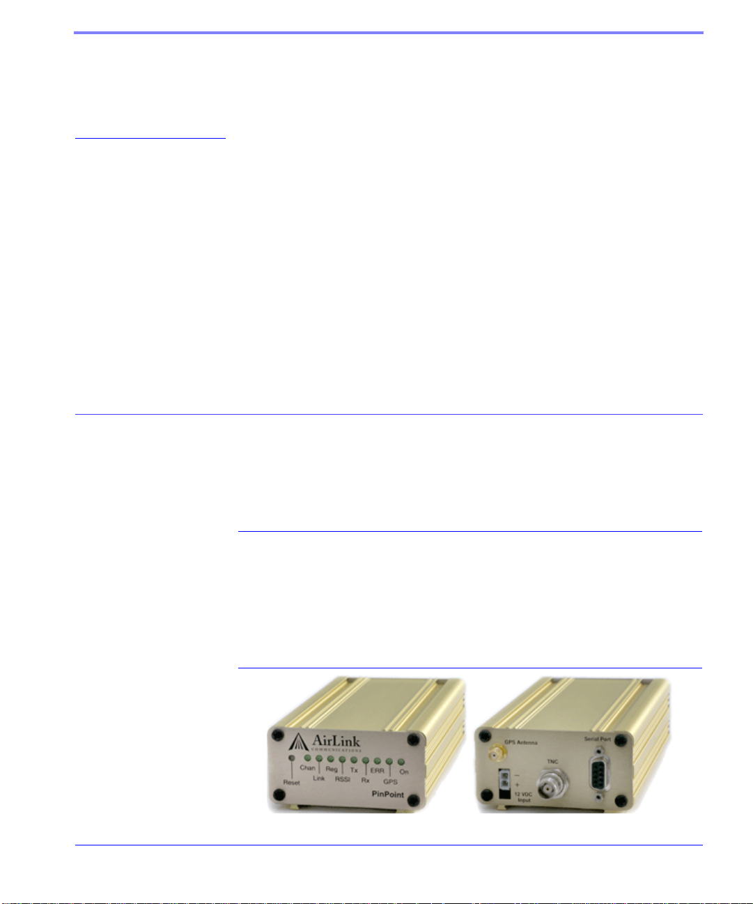
The PinPoint's rugged form factor is ideal for industrial and commercial applications that require real-time communications. The PinPoint provides cellular data
communications for a variety of applications, such as telemetry, public safety,
SCADA, traffic control, traffic metering, transit arrival systems and more.
FIGURE 1. PinPoint front and back
TELUS CDMA/1xRTT PinPoint User Guide Version 2.09 1
Page 11

Introduction to PinPoint CDMA/1xRTT
The PinPoint has several built in features to make it more effective in a variety of
settings. In addition, Airlink provides several modem tools to further enhance the
capabilities of the
Guide.
PinPoint. These features and tools are introduced in this User
• Wireless ACE, Wireless ACE Web, and AceNet
• IPManager
• Modem Doctor
• AirLink Tracking System
• Keepalive and Low Power Mode in high temperature environments
CDMA/1xRTT Overview
Code Division Multiple Access (CDMA) provides a digital cellular telephony system provides wireless Internet access at speeds between 60 and 80 kbps, with bursts
up to 144 kbps.
Establishing a Internet Connection
The Internet Service Provider (ISP) from you to the Internet is TELUS with your
PinPoint as the connection to TELUS.
When your PinPoint is powered on, it automatically searches for cellular service
using CDMA/1xRTT and establishes a PPP (Point to Point Protocol or “dial” up
connection) link to TELUS’s network. As soon as the PinPoint receives its IP, it’s
ready to create a network between your computer or device and TELUS’s network
so you can use TELUS to communicate on the Internet.
To use your PinPoint to connect to the Internet from your computer, you need to
connect the computer directly to the PinPoint’s serial port and use Dial-Up Networking (DUN).
TELUS CDMA/1xRTT PinPoint User Guide Version 2.09 2
Page 12
Introduction to PinPoint CDMA/1xRTT
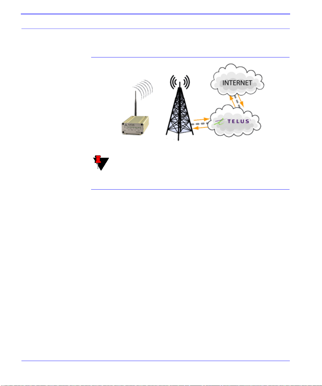
FIGURE 2. Using the PinPoint to connect to the Internet
Note: Private network connections are unique for each configuration and
not covered as part of the standard installation.
Using CDMA/1xRTT to Communicate with Your Equipment
There are two types of addresses in TCP/IP, dynamic and static.
• Dynamic addresses are assigned on a “need to have” basis. Your PinPoint might
not always receive the same address each time it connects with TELUS.
• Static addresses are permanently assigned to a particular account and will
always be used whenever your
address will not be given to anyone else.
If you need to contact the PinPoint, a device connected to the modem, or a host system using the modem, you need to have a known IP (such as one which is static) or
domain name (an IP address which is converted by a DNS server into a word based
name).
Most ISPs (cellular included) use dynamic IP addresses rather than static IP
addresses. A dynamic IP address is suitable for many common Internet uses, such
as web browsing, looking up data on another computer system, or other client func
tion (such as data only being sent out or only being received after an initial request).
PinPoint connects to the Internet. The IP
-
3 TELUS CDMA/1xRTT PinPoint User Guide Version 2.09
Page 13

Introduction to PinPoint CDMA/1xRTT
If you have a dynamic IP address for your PinPoint, you can use a service (such as
IP Manager, covered later in this User Guide) to translate a dynamic IP address to a
fully qualified domain name so you can contact the
Caution: The IP address given to your PinPoint by TELUS must also be
Internet routable if the computer you need to connect to the PinPoint is
not connected directly to TELUS's IP network. Please check with
TELUS to confirm you IP is scheme is correct for your application and
needs.
PinPoint as if it had a static IP.
Common Uses for the PinPoint
The PinPoint’s rugged construction and cellular connection make it ideal for use in
remote and/or industrial locations. Because of its GPS capabilities, the PinPoint is
ideal for vehicle tracking and other situations where noting a moving location is as
important as connecting to a network.
TELUS CDMA/1xRTT PinPoint User Guide Version 2.09 4
Page 14

CHAPTER 2 PinPoint Activation
Your PinPoint needs specific parameters before it can operate on the CDMA/
1xRTT network. Generally TELUS will provide you with the necessary parameters
to get the PinPoint configured.
Connecting the PinPoint to your computer
Your PinPoint’s serial port can be connected directly to most computers or devices
using a standard straight through serial cable.
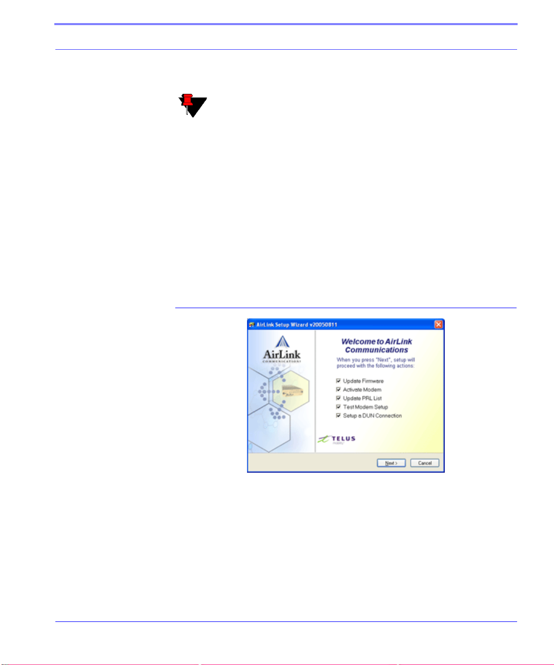
Quick Start Guide and Setup Wizard
The preferred way to configure and activate your PinPoint is via the AirLink Setup
Wizard for TELUS and CDMA/1xRTT. The Quick Start Guide will lead you
through the using the Setup Wizard.
• The PinPoint Setup W izard for CDMA/1xRTT and TELUS is available from the
AirLink web site, http://www.airlink.com/support.
• The Quick Start Guide is also available at the AirLink web site.
TELUS CDMA/1xRTT PinPoint User Guide Version 2.09 5
Page 15
PinPoint Activation
Note: The web site may have a more recent Setup Wizard and Quick
Start Guide than those included with your PinPoint. It is recommended
that you check with the web site for the latest version before installing
your
PinPoint. You will need to look for TELUS, CDMA/1xRTT, and
the PinPoint. Other Setup Wizards may not work to connect you to
TELUS.
To run the Setup Wizard, you will need the Microsoft .NET framework and
Microsoft Windows 98, Microsoft Windows 2000, Microsoft W indows XP , or later .
1. Select Start
2. Select All Programs
3. Select AirLink Communications
4. Select Setup Wizard
5. Select Setup Wizard
FIGURE 1. Setup Wizard Menu
The Quick Start Guide specifies the information you need and will lead you
through the steps.
TELUS CDMA/1xRTT PinPoint User Guide Version 2.09 6
Page 16
PinPoint Activation
Configuring the PinPoint using Wireless ACE
You can configure your modem using Wireless ACE (page 11) or AceNet
(page 12). It is not recommended to activate a modem using either Wireless ACE
or AceNet. An alternate method to configure and activate your PinPoint is by AT
commands (full listing beginning on page 76) sent directly to the modem via a terminal application (page 73). This method is recommended only in situations where
the Setup Wizard is not available and/or the configuration for the PinPoint is
unusual.
PinPoint Indicator Lights
When your PinPoint is connected to power and an antenna, there is a specific pattern to the lights to indicate its operation mode.
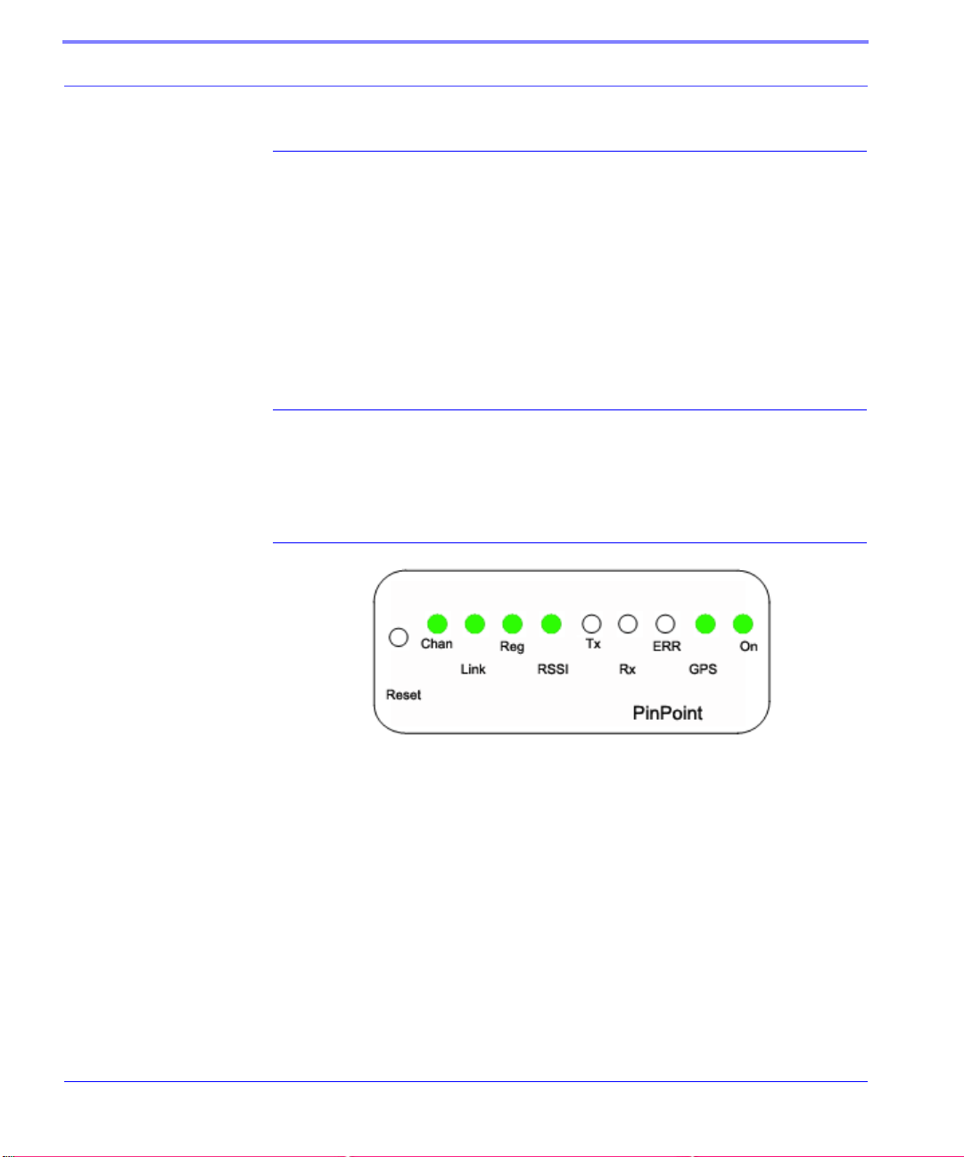
FIGURE 2. PinPoint indicator lights
Tx (transmit) and Rx (receive) - Lights will flash as data is transferred to and
from the
RSSI - Light shows the strength of the signal and may be nearly solid (strong
signal) or flashing (weaker signal). A slow flash indicates a very weak signal.
Reg - Indicates the PinPoint has acquired an IP from TELUS.
Chan - Indicates the modem has acquired a network channel.
Link - Indicate a successful connection to the cellular network.
Pwr - Indicates the power adapter is connected and there is power getting to the
modem.
PinPoint on the remote network.
7 TELUS CDMA/1xRTT PinPoint User Guide Version 2.09
Page 17

PinPoint Activation
The Reset button performs the same function as unplugging power from the
modem and plugging it back in. Reset will not alter any saved configuration
settings.
TELUS CDMA/1xRTT PinPoint User Guide Version 2.09 8
Page 18

CHAPTER 3 PinPoint Utilities
AirLink offers a suite of utilities to optimize your PinPoint’s performance, allowing
you to remotely view status and make changes to the configuration as needed.
• AceView
• Wireless ACE and Wireless ACE Web
• AceNet
• Modem Doctor
• AirLink Tracking System
This section of the PinPoint User Guide covers basic information about these utilities. For additional information on a specific utility, please refer to the user guide
for that utility.
These utilities, except AceNet and AirLink Tracking System (ATS), are free of
charge to those who own AirLink modems. You can download them and their user
guides from the AirLink web site: http://www.airlink.com/support. Contact your
dealer or AirLink for information on AceNet and AirLink Tracking System.
Note: AceView, Wireless ACE, and AceNet require the Microsoft .NET
framework and Microsoft Windows 98, Windows 2000, W indows XP, or
later. Wireless ACE Web requires Internet Explorer 6.0 or later with
ActiveX enabled.
TELUS CDMA/1xRTT PinPoint User Guide Version 2.09 9
Page 19
PinPoint Utilities
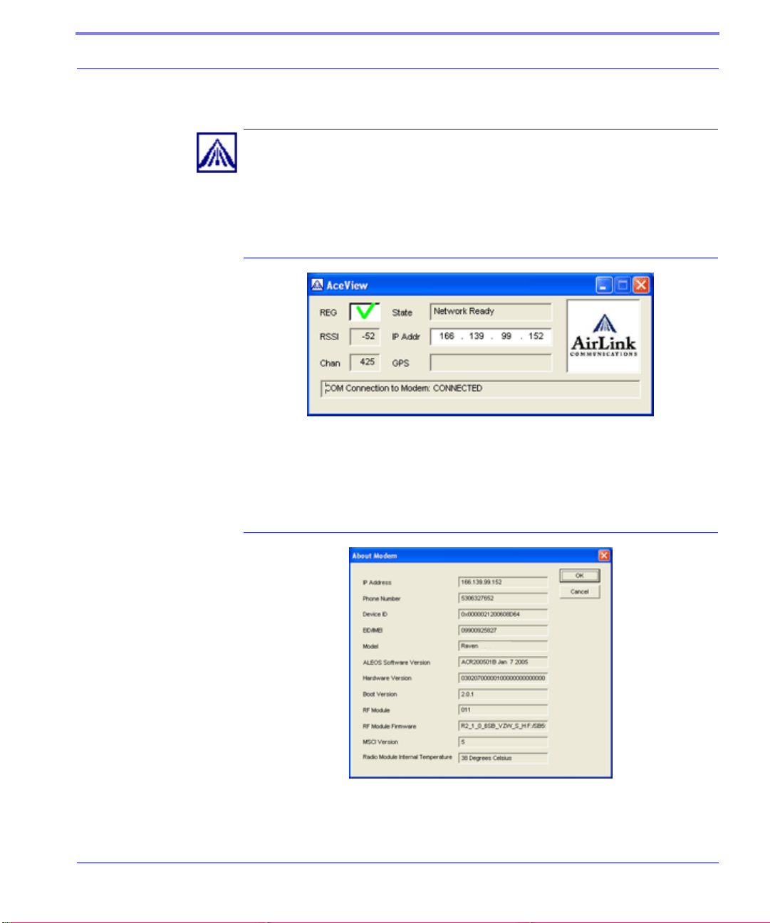
AceView
AceView is a low-profile monitoring tool to view the status of your AirLink PinPoint and display network status, IP address, RSSI strength, firmware version, and
other basic information.
FIGURE 1. AceView
You can connect to your PinPoint locally or remotely using a known IP address or a
fully qualified domain name. The display is updated periodically as AceView polls
the
PinPoint at a specified interval. GPS is available only for PinPoint modems.
FIGURE 2. AceView: About PinPoint
TELUS CDMA/1xRTT PinPoint User Guide Version 2.09 10
Page 20
PinPoint Utilities
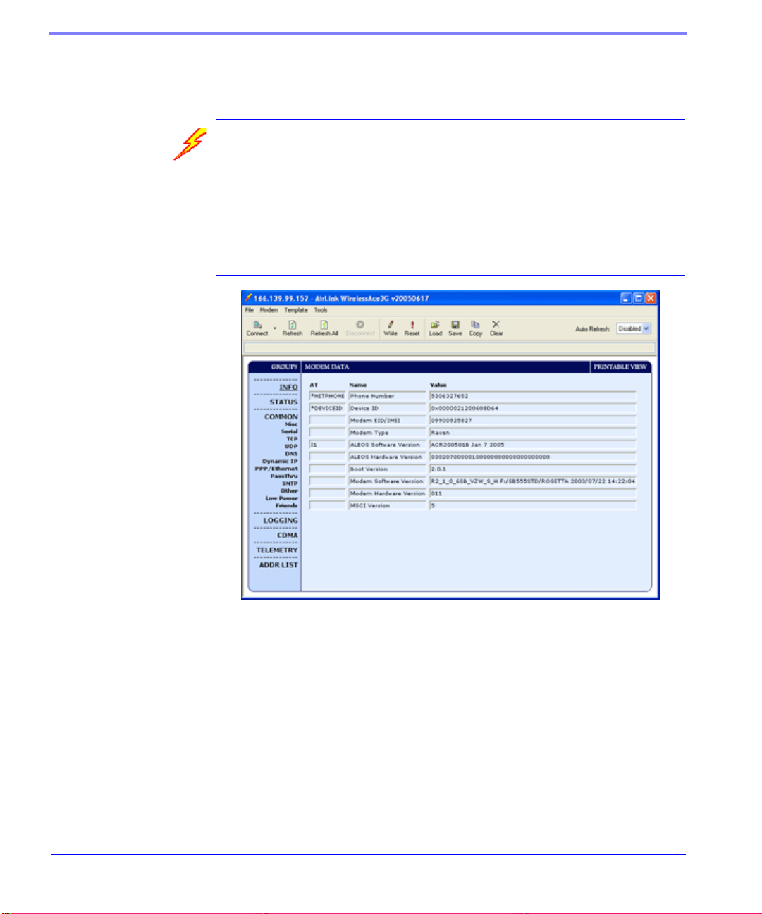
Wireless ACE and Wireless ACE Web
Wireless AirLink Configuration Executive (ACE) and Wireless Ace W eb allow you
to monitor your
modem. Wireless ACE Web has a web-based interface and covers nearly the same
range of features a Wireless ACE. Features discussed in this section apply to both
versions unless otherwise noted.
FIGURE 3. Wireless ACE
PinPoint either remotely or locally with a direct connection to the
Wireless ACE can be used to monitor your PinPoint, view modem status, or change
the configuration of your PinPoint. You can even save a template and, using Wireless ACE or AceNet, apply it to another AirLink modem.
Wireless ACE provides a graphical interface for entering AT commands. See “AT
Commands” on page 76 for a full listing of the AT commands for your PinPoint.
11 TELUS CDMA/1xRTT PinPoint User Guide Version 2.09
Page 21
PinPoint Utilities
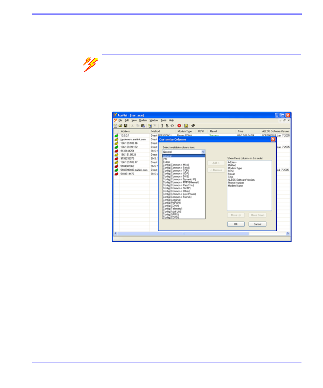
AceNet
With AceNet you can monitor several AirLink modems at the same time. The
modems can be connected locally or remote. Several features can be displayed and
logged. AceNet is a seperate product which can be purchased from AirLink.
FIGURE 4. AceNet
Using a template from Wireless ACE, you can change the configuration in several
modems at the same time and can check and update their firmware as well. AceNet
also features logging to a database and charting for the monitored modems.
With AceNet, you can connect to modems locally via serial or Ethernet or remotely
via TCP/IP or SMS.
TELUS CDMA/1xRTT PinPoint User Guide Version 2.09 12
Page 22
PinPoint Utilities
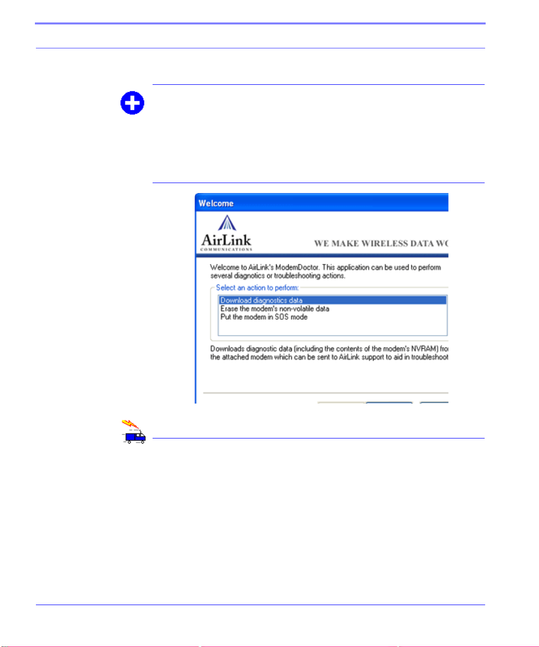
Modem Doctor
Modem Doctor is a troubleshooting utility. This utility will allow you to get a log
file of the
current configuration completely, and temporarily set the PinPoint to a known
serial configuration to aid in trouble shooting.
PinPoint activity which you can then send to AirLink support, erase the
FIGURE 5. Modem Doctor
AirLink Tracking System
The AirLink Tracking System (ATS) is a feature-rich vehicle tracking system that
uses cellular technology to transmit vehicle and location information to a Tracking
Control console. ATS also employs the satellite based Global Positioning System
(GPS) to obtain location and velocity information.
ATS is a seperate product which can be purchased from AirLink.
13 TELUS CDMA/1xRTT PinPoint User Guide Version 2.09
Page 23

CHAPTER 4 DNS: Using Names
Instead of IP addr esses
A domain name is a name of a server or device on the Internet which is associated,
generally, with an IP address. In a way, a domain name is like the street address of
your house with the phone number being like the IP address. You can contact the
house either by going to the address (name) or by calling the phone number (IP
address).
Domain Name Service (DNS) is a network service which translates, or redirects,
the IP address, allowing someone to contact that address via the name. A DNS
server is registered to handle all addresses of a particular domain (much like the
post office for a particular town or city is known to the post offices of all other
towns and cities and is authorized to give the addresses of locations in its own loca
tion).
-
Configuring DNS
The PinPoint has an internal DNS resolver with which it can query DNS servers in
order to translate names into IP addresss which it can then use internally. Generally, when your PinPoint receives its IP address from TELUS, it will also be configured to use TELUS’s DNS servers to use for resolving (or translating) names to IP
addresses. In that case, the only one which is not overwritten is the alternate DNS.
TELUS CDMA/1xRTT PinPoint User Guide Version 2.09 14
Page 24
DNS: Using Names Instead of IP addresses
You can use AT commands (page 76), Wireless ACE (page 11), and ACE Net
(page 12) using a template built from Wireless ACE to configure DNS in your PinPoint.
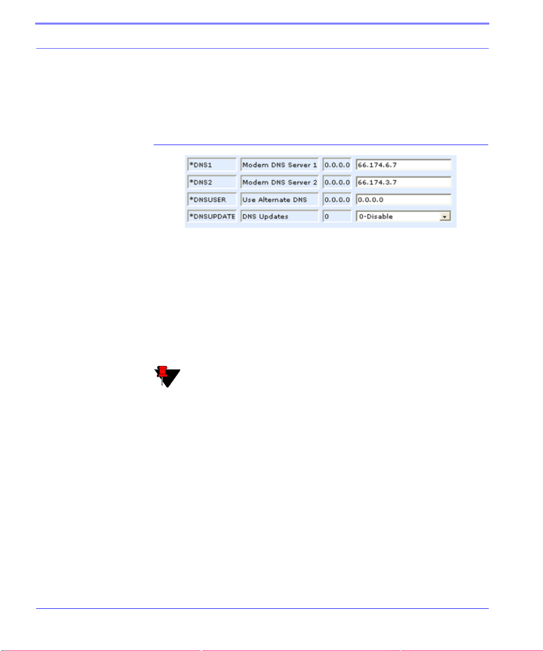
FIGURE 1. Wireless ACE: DNS
*DNS1 and *DNS2 - Set these to your primary and secondary DNS servers.
These maybe be overwritten by
TELUS when your PinPoint gets its IP address.
*DNSUSER - Set this, if desired, to an additional DNS server to query first
before the primary or secondary (just as a hosts file is queried first on a com
-
puter). If *DNSUSER is set to 0.0.0.0, it will be ignored.
*DNSUPDATE - This command sets how often you want DNS Updates to be
forced. Otherwise the
PinPoint will only send updates when it is reset, powered
up, or the IP address granted by the network changes.
Note: If you will be using your PinPoint to communicate with another
AirLink modem and both are using IP Manager (page 16) to translate
dynamic IP addresss to domain names, it is recommended that you set
*DNSUSER to the IP address for IP Manager. IP Manager’s updates
occur more frequently than
TELUS’s DNS servers decreasing the time
between IP address change and address resolution.
PPP-Peer
The PinPoint uses the unqualified domain name of “ppp-peer” when it is PPP or
SLIP address mode to resolve the address of the device or computer connected via
PPP or SLIP address. If the
PinPoint is not in PPP or SLIP address mode, “ppp-
peer” will resolve to 0.0.0.0.
15 TELUS CDMA/1xRTT PinPoint User Guide Version 2.09
Page 25

CHAPTER 5 IP Manager
IP Manager translates a dynamic IP address to a fully qualified domain name so
you can contact
Since TELUS frequently does not offer static IP addresses, IP Manager is a free service provided by AirLink for your PinPoint to translate a dynamic IP address into a
fully qualified domain name so it can be contacted directly on the Internet.
PinPoint by name as if it had a static IP.
• Dynamic IP addresses are granted only when a modem or other device is con-
nected and can change each time the modem or device reconnects to the network.
• Static IP addresses are granted the same address every time the modem or
device is connected.
A dynamic IP address is suitable for many Internet activities such as web browsing,
looking up data on another computer system, data only being sent out, or data only
being received after an initial request. However, if you need to contact the
directly, a device connected to the modem, or a host system using the PinPoint, a
dynamic IP won’t give you a reliable address to contact (since it may have changed
since the last time it was assigned).
TELUS CDMA/1xRTT PinPoint User Guide Version 2.09 16
PinPoint
Page 26

IP Manager
Fully Qualified Domain Name
A fully qualified domain name (FQDN) generally has several parts.
• Top Level Domain (TDL): The TDL is the ending suffix for a domain name
(.com, .net, .org, etc.)
• Country Code Top Level Domain (ccTDL): This suffix is often used after the
TDL for most countries except the US (.ca, .uk, .au, etc.)
• Domain name: This is the name registered with ICANN (Internet Corporation
for Assigned Names and Numbers) or the registry for a the country of the
ccTDL (i.e. if a domain is part of the .ca TDL, it would be registered with the
Canadian domain registry). It is necessary to have a name registered before it
can be used.
• Sub-domain or server name: A domain name can have many sub-domain or
server names associated with it. Sub-domains need to be registered with the
domain, but do not need to be registered with ICANN or any other registry . It is
the responsibility of a domain to keep track of its own subs.
A URL (Universal Resource Locator) is different from a domain name in that it
also indicates information on the protocol used by a web browser to contact that
address, such as http://www.airlink.com.
• .com is the TDL
• airlink is the domain (usually noted as airlink.com since the domain is specific
to the TDL)
• www is the server registered with AirLink.com
• http:// is the protocol (html or web) used to access the webpage for AirLink
Dynamic Name Resolution
When an IP address is not expected to change, the DNS server can indicate to all
queries that the address can be cached and not looked up for a long period of time.
Dynamic DNS servers, conversely, have a short caching period for the domain
information to prevent other Internet sites or queries from using the old informa
tion.
17 TELUS CDMA/1xRTT PinPoint User Guide Version 2.09
-
Page 27

IP Manager
If the PinPoint is configured for Dynamic IP , when the PinPoint first connects to the
Internet, it sends a IP change notification to IP Manager. IP Manger will acknowledge the change and update the DNS record. The changed IP address will then be
the address for the
PinPoint’s configured name.
Once the PinPoint’s IP has been updated in IP Manager, it can be contacted via
name. If the IP address is needed, you can use the domain name to determine the IP
address.
The fully qualified domain name of the PinPoint will be a subdomain of eairlink.com.
Note: Earlink.com is a domain name owned and registered by AirLink
for IP Manager.
Configuring the PinPoint for Dynamic IP
To configure the Dynamic IP settings in yo ur PinPoint so that it will use IP Manager, you can use AT commands (page 76), using direct serial communication or
Telnet (page 73), Wireless ACE (page 11), and ACE Net (page 12) using a template
built from Wireless ACE.
To configure your AirLink modem to be addressed by name, the mo dem needs to
have 4 elements configured.
FIGURE 1. Wireless ACE: Dynamic IP (IP Manager configuration)
1. Modem name: The name you want for the modem.
TELUS CDMA/1xRTT PinPoint User Guide Version 2.09 18
Page 28

IP Manager
2. Domain: Eairlink.com is the IP Manager domain provided by AirLink.
3. IP Manager IP Address: The IP or domain name of the dynamic DNS server.
Earlink.com is the IP Manger server provided by AirLink. Note: To use the
name here instead of the IP, you need to have DNS set up in your
PinPoint. See
“DNS: Using Names Instead of IP addresses” on page 14.
4. IP Manager update interval: How often you want the address sent to IP Man-
ager. If this is set to zero, the modem will only send an update if the IP changes
(i.e. if the modem is reset or is assigned a different IP).
In Wireless ACE, select Dynamic IP to configure your modem to use IP Manager.
You can configure a second dynamic server as a backup, secondary, or alternate
server.
Note: For the Modem Name, you should use something which is unique
but also easy to remember. Your company name or the intended function
of the modem are recommended. If you have more than one modem,
append a number for each.
Restrictions for Modem Name
• Must begin with a letter or number
• Can include a hyphen (-)
• Cannot contain spaces
• Must be no longer than 20 characters total
19 TELUS CDMA/1xRTT PinPoint User Guide Version 2.09
Page 29

CHAPTER 6 Keepalive
It is not uncommon for your PinPoint to be disconnected from TELUS after an
extended period of inactivity. This is generally a feature intended to reduce your
charges for inactive use.
Keepalive is used to test and maintain the PinPoint’s connection to TELUS by pinging an IP address after a specified period of inactivity. Keepalive is recommended
for users who have a remote terminated modem that infrequently communicates to
the network. Keepalive is also recommended if you have experienced issues where
the modem can no longer be reached remotely.
When Keepalive pings the IP address, an acknowledgement indicates there is an
active connection to the network. If the modem does not receive a response from
the IP address, it will retry 5 times in 5 second intervals. The
reset the radio module after 5 failed attempts and reconnect to TELUS.
PinPoint will then
Configuring Keepalive
As with all other aspects of the PinPoint’s configuration, you can use Wireless Ace
or Wireless Ace Web (page 11), AceNet (page 12), or direct serial communication
or T elnet (page 73) to configure Keepalive.
TELUS CDMA/1xRTT PinPoint User Guide Version 2.09 20
Page 30
Keepalive
To set the Keepalive using Wireless ACE, select Other from the menu on the left.
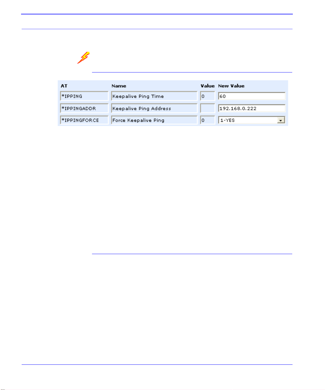
FIGURE 1. Keepalive Configuration in Wireless ACE
*IPPING sets the interval, in minutes, you want Keepalive to test the network connection. To disable Keepalive, set *IPPING to 0 (default setting).
*IPPINGADDR sets the IP address you want to use for the test. If *PPINGADDR
is left blank or is set to an invalid IP address (i.e. an IP which is unreachable or one
which is not a valid IP address), the modem will reset itself on a regular interval.
*IPPINGFORCE sets whether you wish the network connection test to occur only
if there is no activity. Set to 1, IPPINGFORCE will force the ping to occur at the
IPPING interval regardless of any oth e r network activity. When *IPPINGFORCE
is set to 1, the modem does a complete modem reset, in addition to resetting the
connection. When the modem is reset, it could take a few minutes to reconnect to
the network.
Data usage using Keepalive.
When using Keepalive, be aware that a ping moves approximately 66 bytes of data
over the network and is billable by the carrier. The following *IPPING settings
will incur approximate monthly data usage in addition to any other data usage:
• 5 min. will use 1.2mb / month
• 15 min. will use 400k / month
• 30 min. will use 200k / month
• 60 min. will use 100k / month
• 120 min. will use 50k / month
21 TELUS CDMA/1xRTT PinPoint User Guide Version 2.09
Page 31

CHAPTER 7 Host Modes
The PinPoint can be in one of six communication modes as the Host to the computer or other device attached to the serial port of the PinPoint.
AT: The PinPoint accepts and responds to standard, Hayes-style AT commands.
This is enabled by default.
PassThru: Direct connection to internal hardware (OEM Module) of the PinPoint.
PPP: The PinPoint uses PPP to communicate.
SLIP: The PinPoint uses SLIP to communicate.
UDP P AD: Any data received on the serial port is assembled into UDP packets and
send to the session's associated IP and Port (described later). Any responses
received from the associated IP and port destined for the modem's Device Port are
unwrapped and sent out the
TCP P AD: Any data received on the serial port is packaged into TCP messages and
sent to the associated connection's IP and Port (described later). Any data received
from the TCP peer is unwrapped and sent out the
The PinPoint can be programmed to enter any of the modes, except PassThru, automatically on power up. This is done setting the Startup Mode Default (refer to MD
TELUS CDMA/1xRTT PinPoint User Guide Version 2.09 22
serial port.
serial port.
Page 32

Host Modes
in the AT Command listing, page 84) to the desired mode. If this setting is nonzero, the modem will enter the specified mode after 5 seconds. If you want to cancel this behavior, the ATMD0 command can be used before the 5-second time-out
expires.
If the modem is in any mode other than AT or PassThru, the AT command mode
can be re-entered by:
• Deactivating DTR (if &D2 or Ignore DTR, S211, is not set).
• Issuing the +++ escape sequence (if Disable AT Escape, DAE, is not set).
• Resetting or Power cycling the modem.
PassThru Mode can only be exited by resetting the modem.
Note: DTR needs to be asserted (S211=1 or &D0) by the host before PPP
Mode, SLIP Mode, UDP PAD Mode, or TCP PAD Mode can be entered.
AT Mode
AT commands are used to configure the modem, command it to do something, or
query a setting. For a full listing of the AT commands, refer to
AT commands must always be terminated by <CR> (ASCII character 0x0D).
If E=1 (Echo On), the AT command (including the terminating <CR>) will be
displayed (output) before any responses.
Two settings affect the format of AT command output: V (Verbose) and Q (Quiet).
If Q=1 (Quiet On), no result codes are output whatsoever, so there is no
response generated by a (non query) command.
If Q=0 (Quiet Off), result codes are output. The format of this output is then
affected by the Verbose setting.
If Quiet mode is off, the result code is affected as follows:
For V=1 (Verbose mode), the textual result code is surrounded by <CR><LF>
and any AT query response is also surrounded by <CR><LF>.
23 TELUS CDMA/1xRTT PinPoint User Guide Version 2.09
page 76.
Page 33

Host Modes
For V=0, (Terse mode), a numeric result code is output with a single trail ing
<CR> (no <LF> is output), while any AT query response is followed by
<CR><LF> (there is no preceding output).
For example, possible output to the AT command "AT<CR>" (assuming quiet
mode is not on) is:
<CR> - if V=0
<CR><LF>OK<CR><LF> - if V=1
PassThru Mode
In PassThru mode, the PinPoint does not behave normally, all serial port communication is passed directly between the internal hardware and the computer connected
directly to the modem. This mode can be used to configure hardware-specific set
tings (e.g., for provisioning, etc.)
Issuing the "A T\APASSTHRU" enters this mode. The modem responds with OK, at
which point a direct connection to the internal hardware is established.
-
PassThru Mode can only be exited by resetting the modem.
Some internal hardware requires upwards of 20 seconds before AT commands can
be entered, so be patient if there seems to be no response to AT commands.
Warning: PassThru can only be exited by resetting or power-cycling the
modem. This mode cannot be entered via a Telnet session.
PassThru Mode allows only specific AT commands. Those commands which are
used with ALEOS only will be unavailable. For the many of the commands avail
able in PassThru mode, refer to page 105. Most of these commands are not available except when the modem is in PassThru Mode. The commands usable also
depend heavily on the modem model number (found on the label on the top of the
modem).
Note: ALEOS is disabled in PassThru Mode. You cannot use most
ALEOS specific commands while the modem is in PassThru Mode.
TELUS CDMA/1xRTT PinPoint User Guide Version 2.09 24
-
Page 34

Host Modes
PPP Mode
In PPP mode, the PinPoint acts as a PPP server, providing an IP address, and DNS
servers (if available) to the Host.
PPP mode is entered from the AT mode by using any of the following commands:
AT\APPP<CR>
ATDT10.0.0.1<CR>
ATDT10001<CR>
ATD#19788<CR>
CLIENT<CR>
In response to any of the preceding commands, the modem will respond with
CONNECT<CR><lf> and is ready for the host to begin PPP negotiations.
The IP received by the host in the resulting negotiation will either be a private (nonroutable) IP or a public (network-routable) IP provided by the network, depending
on the settings of *HOSTPRIVMODE [S300]. If *HOSTPRIVMODE=1, the value
of the private IP an be determined beforehand by querying S110. The private IP to
be used can be defined with the command A T*HOSTPRIVIP=192.168.100.33 sub
stituting the desired IP address.
-
Using a private IP insulates the PPP client from changes in IP addresses of the
underlying network. The
on all packets.
If a public IP address is being used, any changes in the IP (as determined by the
wireless network) will result in the PPP link to the host being disconnected, requir
ing the host to reinitiate it. The public IP is passed to the host in the PPP negotiations, so when the network forces a change, the modem has to force the host to
renegotiate the PPP link to make this happen.
PinPoint will perform basic NAT-like address translation
Slip Mode
SLIP mode is entered be using the "AT\ASLIP" command. As in PPP Mode, the IP
address that the host assumes is affected by the setting of S300. SLIP do es not
negotiate the IP with the host, so before making a SLIP connection, the host SLIP
driver must be configured to use the IP specified by querying S110.
25 TELUS CDMA/1xRTT PinPoint User Guide Version 2.09
-
Page 35

Host Modes
UDP Pad Mode
When the modem is in UDP PAD (Packet Assembly and Disassembly) Mode, all
characters received on the
the PinPoint’s remote IP address/port, and any packets received from the same IP/
port-destined for the PinPoint’s Device Port (see *DPORT)--are disassembled and
dumped onto the serial line.
A UDP session is initiated by one of the following events:
• Using the Dial UDP (DP) AT command (ex. ATDP192.168.3.23/3456)
• Setting the Startup Mode Default (MD) to 3 (UDP) so that a UDP session is
entered automatically when the modem powers up. Serial data will be sent to
the IP/port specified in S53.
• An incoming UDP packet is received and
• UDP auto answer is enabled (S82=2)
• The destination IP address matches that in S53
• Or allow any IP is set (AIP=1)
• The modem is in AT mode [not in a current UDP or TCP session]
serial port are assembled into UDP packets and sent to
UDP packet assembly is affected by the values of S50 (PAD Forwarding Time-out)
and S51 (PAD Forwarding Character). Data received in the serial buffer will be
transmitted when the idle inter-character time-out specified in S50 (in tenths of sec
onds) occurs or when a character is received that matches S51 (if non-zero).
UDP Auto Answer
UDP auto answer (previously called UDP half-open) is set with S82=2. When set,
the
PinPoint will automatically establish a UDP session to the source IP address
and port of the UDP packet received. The PinPoint will remain "locked" to this one
remote IP/port until no data is sent or received for the time interval defined in the
UDP auto answer time-out (S83). During this session, packets from other IP/port
addresses will be rejected, unless *UALL is set. Whether or not an incoming
packet will cause the modem to enter a UDP session is always dependent on the
S53 and AIP settings.
When idle, after the time-out has occurred, the PinPoint is in A T command mode on
the serial port, and any valid AT command may be entered during this time.
The Normal UDP Mode (MD3) can be combined with UDP auto answer to cause
the incoming serial data to be sent in UDP packets (instead of being treated as AT
TELUS CDMA/1xRTT PinPoint User Guide Version 2.09 26
-
Page 36

Host Modes
commands), while allowing sessions to be established from different UDP sources.
A UDP session will be initiated either by incoming serial data or by an incoming
UDP packet. The session, started by either method, will be terminated when no data
has been sent or received for the S82 period. Once the session terminates, another
may be initiated by either means.
When the session is initiated by serial data, the new session will be established
using the destination address specified in S53. The S53 setting can be changed if
the connect to last UDP setting (*UDPLAST=1) is set. The address in S53 will be
updated to reflect the address of the last session initiated by an incoming UDP
packet. So that when new data is received over the host
state, a session will be re-established with the last address. (This behavior is the
same as the previous Hybrid2 (MD6) mode).
Note: TCP auto answer (S0) may also be set simultaneously with UDP
auto answer. Then, when in the idle state, the modem will accept either
a TCP or UDP incoming packet, and enter a TCP or UDP session as
appropriate.
serial port while in the idle
Reliable UDP
Reliable UDP adds a simple protocol on top of UDP to provide reliable deli v e ry of
data. When data is received from the host
data, containing a message type and a sequence number. The PinPoint will continue
to send this data (buffering any received data in the meantime) until it receives an
acknowledgement with this sequence number. If an acknowledgement is not
received within the time-out period (specified in S7), the data will be retransmitted.
This will continue until an acknowledgement is received or the modem is reset.
Likewise any UDP packets received by the
ple header. The PinPoint will issue an acknowledgement for any valid packets
which are received.
Configure the PinPoint as for a normal UDP session. Set the Startup Mode Default
to 3, and the UDP Mode Default to 7 (ATMD73). If using two modems, configure
the Destination IP and Port in each to point to each other. Serial data will then be
sent reliably between the two
Note: Although it adds reliability, the simple implementation of the
Reliable UDP mode in the PinPoint does not check for duplicate packets.
serial port, a 2 byte header is added to the
PinPoint are expected to have this sim-
27 TELUS CDMA/1xRTT PinPoint User Guide Version 2.09
Page 37

Host Modes
Multicast UDP
Multicast UDP results in any data received from the host serial port being sent to all
the clients in the Modbus list. The remote port number is taken from S53. To avoid
flooding the network, the packets are sent to each client with a 20ms pause in
between. The receipt of UDP packets works as in normal UDP mode (i.e. bound by
the value S53 and/or AIP). Since it may take a while to transmit the data to all hosts
(especially if all 20 Modbus entries are used and name resolutions are required),
new data received from the host port is buffered until current transmissions to all
hosts are finished.
Enter the list of target IPs in the Modbus IP list. The index numbers in the IP list
aren't used. Configure the Raven as for a normal UDP session. Set the Startup
Mode Default to 3, and the UDP Mode Default to 8 (ATMD83). Configure the
Destination port to match the device port of the remote modems.
TCP PAD Mode
When the PinPoint is in a TCP session, all characters received on the serial port are
assembled into TCP packets and sent to the mode's remote IP address/port, and any
packets received from the remote end of the TCP connection are disassembled and
dumped onto the serial line.
• A TCP connection is established by one of the following methods:
• Using the Dial TCP (DT) AT command (ex. ATDT192.168.3.23/3456)
• TCP auto answer is enabled (S0), a TCP connection request is received, and the
modem is not in a data session.
• Data is received on the serial port and
• The Startup Mode Default (MD) is 4 (auto TCP)
• The remote TCP destination, as defined in S53, successfully responds to the
TCP connection request.
The value of S7 (TCP Connection Time-out) specifies the number of seconds to
wait, after initiating a TCP connection attempt, for a successful connection to be
established. If the connection has not been successfully established before the timeout occurs, ERROR/BUSY is returned.
TELUS CDMA/1xRTT PinPoint User Guide Version 2.09 28
Page 38

Host Modes
TCP packet assembly is affected by the values of S50 (PAD Forwarding Time-out)
and S51 (PAD Forwarding Character). Data received in the serial buffer will be
transmitted when the idle inter-character time-out specified in S50 (in tenths of sec
onds) occurs or when a character is received that matches S51 (if non-zero).
The TCP session will be terminated if no data is transmitted or received for the time
interval specified in TCPT and TCPS. TCPT is the number of minutes (TCPS=0)
or seconds (TCPS=1) used for this idle time-out.
Warning: TCPT should never be 0 when using the TCP mode. A broken
TCP session can result in the modem being left with a TCP half-open
connection that can only be terminated with a reset.
TCP Auto Answer
TCP auto answer (S0=1|2) also allows a TCP connection request to be "answered"
when the modem is idle, not in a data session. The TCP connection request's desti
nation port has to match the modem's device port.
-
-
Note: UDP auto answer may also be set simultaneously with TCP auto
answer. Then, when in the idle state, the modem will accept either a
TCP connection request or UDP incoming packet, and enter a TCP or
UDP session as appropriate.
Hybrid Modes
Some previous hybrid modes (MD=5, 6) are no longer implemented as special,
unique modes. Now that UDP auto answer (UDP Half-open, S82=2) can be
enabled in conjunction with UDP PAD mode (MD3), effectively this is the same as
MD5 and MD6 previously accomplished. Setting MD5 and MD6 are still sup
ported, but not recommended.
-
29 TELUS CDMA/1xRTT PinPoint User Guide Version 2.09
Page 39

Host Modes
TABLE 1. Hybrid Mode Settings
A T Setting Hybrid (MD5) Hybrid2 (MD6)
MD 3 3
S82 2 2
S0 1 1
*UDPLAST 0 1
TELUS CDMA/1xRTT PinPoint User Guide Version 2.09 30
Page 40

CHAPTER 8 External Inputs and
Power Contr ol
The PinPoint has special features for use in a mobile environment. The PinPoint
can be configured to monitor the inputs on its serial port and respond to specific
types of events. The
order to conserve power.
PinPoint can also be configured to change its power mode in
Capturing Events via External Inputs
The RS232 DB9 interface (the serial port) can be connected to digital switches and
configured to capture contact closures using RTS and DTR to signal external or
physical events (such as a tow bar being activated, opening a door or trunk, the car
is turned on or off, etc.).
Setting the DTR and RTS
You can use either Wireless ACE (page 11) or direct serial communication, or Telnet (page 73) to configure the modem using AT commands (page 76).
In Wireless ACE, select PinPoint from the menu on the left.
TELUS CDMA/1xRTT PinPoint User Guide Version 2.09 31
Page 41

External Inputs and Power Control
FIGURE 1. Wireless ACE: DTR and RTS
T o turn on the DTR (pin 4) digital sensing in the modem, *DTRI should be set to 1.
T o turn on the RTS (pin 7) digital sensing, *RTSI should be set to 1.
Note: To use only DTR or only RTS, you only need to configure the one
you will be using.
Connecting to the Serial Port
You can connect a standard RS232 serial cable to the The PinPoint serial port. If
you want to use the DTR switch, wire in a Normally Open switch between the DTR
(pin 4) and signal ground (pin 5), the
ground (refer to the figures below). If you want to use the RTS switch, use RTS
(pin 7) to the ground (can use the same ground as DTR).
PinPoint’s external case, or the power
Caution: Never apply voltage to the DTR or RTS inputs. DTR and
RTS can only be switched open or closed to ground.
When the switch is closed, a GPS packet will be sent to the destination IP address
indicating that a contact closure has taken place (an external physical event has
occurred).
FIGURE 2. PinPoint back
See “RAP Configuration” on page 40.
TELUS CDMA/1xRTT PinPoint User Guide Version 2.09 32
Page 42

External Inputs and Power Control
FIGURE 3. PinPoint Serial Port Pinouts
FIGURE 4. DTR and RTS switches using Pin 5 (signal GND) as the common
ground
Power Modes
The PinPoint can be configured to switch a low-power mode in response to specific
events in order to conserve a vehicle's battery life.
The PinPoint can power down when the voltage to the modem drops below a configured threshold (generally caused by the vehicle being turned off), or when DTR
changes (commonly a contact or voltage controlled by the key switch, signaling
when the vehicle is turned off).
Note: If one or both DTR or RTS have been configured to be used as
digital inputs through the AirLink Tracking System (ATS), then low
power mode cannot be configured to respond to DTR.
33 TELUS CDMA/1xRTT PinPoint User Guide Version 2.09
Page 43

External Inputs and Power Control
Power Effect on Modem State
Once the transition from powered on to low-power mode starts, the modem will
change state to AT mode. This results in the current mode (e.g. PPP, TCP, etc.)
being gracefully terminated. For the brief period when the modem is preparing for
low-power mode, the modem will remain in AT mode (i.e. won't auto-answer , ATD
will fail, etc.). Once low-power mode is entered, the modem will then discard any
data received on the host port.
When the modem is woken from low-power mode, the same behavior occurs as
upon power on. The modem starts in AT mode, and then after 5 seconds will enter
the default mode (
See “Host Modes” on page 22).
TELUS CDMA/1xRTT PinPoint User Guide Version 2.09 34
Page 44

CHAPTER 9 Global Positioning
System
The PinPoint is equipped with a GPS receiver to ascertain its position to track the
movements of a vehicle or other devices which move. The PinPoint relays the
information of its location as well as other data for use with AirLink Tracking System (ATS) or other such tracking applications.
GPS Overview
The Global Positioning System (GPS) is a satellite navigation system used for
determining a location and providing a highly accurate time reference almost any
where on Earth. The US military refers to GPS as Navigation Signal Timing and
Ranging Global Positioning System (NAVSTAR GPS).
GPS consists of a "constellation" of at least 24 satellites in 6 orbital planes. Each
satellite circles the Earth twice every day at an altitude of 20,200 kilometres
(12,600 miles). Each satellite is equipped with an atomic clock and constantly
broadcasts the time, according to its own clock, along with administrative informa
tion including the orbital elements of its motion, as determined by ground-based
observatories.
TELUS CDMA/1xRTT PinPoint User Guide Version 2.09 35
-
-
Page 45

Global Positioning System
A GPS receiver, such as the PinPoint, generally receives signals from four satellites
in order to determine its own latitude, longitude, and elevation. Using time synced
to the satellite system, the receiver computes the distance to each satellite from the
difference between local time and the time the satellite signals were sent (this dis
tance is called psuedoorange). The locations of the satellites are decoded from their
radio signals and a database internal to the receiver. This process yields the loca
tion of the receiver. Getting positioning information from fewer than four satellites,
using imprecise time, using satellites too closely positioned together, or using satel
lites too close to the Earth’s curve will yield inaccurate data.
The GPS data is then transmitted to a central location which uses a tracking application to compile information about location, movement rates, and other pertinent
data.
-
-
AirLink Remote Access Protocol (RAP)
The AirLink Remote Access Protocol (RAP) uses the User Datagram Protocol
(UDP) and is a proprietary binary message format. RAP has been desi gned to work
specifically with AirLink Tracking System (ATS), but other 3rd party applications
have been developed to take advantage of the RAP messaging format. AirLink
RAP is also referred to as AirLink Binary/ATS.
-
National Marine Electronics Association (NMEA)
National Marine Electronics Association (NMEA) is a protocol by which marine
instruments and most GPS receivers can communicate with each other. NMEA
defines the format of many different GPS message (sentence) types, which are
intended for use by navigational equipment.
Trimble ASCII Interface Protocol (TAIP)
Trimble ASCII Interface Protocol (TAIP) is a digital communication interface
based on printable ASCII characters over a serial data link. TAIP was designed spe
cifically for vehicle tracking applications but has become common in a number of
other applications, such as data terminals and portable computers, because of its
ease of use.
TELUS CDMA/1xRTT PinPoint User Guide Version 2.09 36
-
Page 46

Global Positioning System
Real-Time Clock Sync
Every hour, the PinPoint will sync the internal Real Time Clock (RTC) with the
Coordinated Universal Time (UTC) received from the GPS satellites.
Applications, such as ATS and the Event Browser, will then translate the time
reported by the
zone using the UTC offset (i.e. California is UTC-8 and New York is UTC-5).
PinPoint as part of the GPS message to the appropriate local time
Note: Wireless ACE displays the current time (UTC) set in the modem
and does not translate it to the local time zone. If the modem is in California and it is 8 a.m., the modem’s time will be shown as 4 p.m, since
UTC is 8 hours “ahead” of Pacific time.
Configuring the PinPoint for GPS
To configure your modem’s GPS settings, you can use either Wireless ACE
(
page 11), direct serial communication or Telnet (page 73) to configure the modem
using AT commands (page 76). The configuration examples in this chapter all use
Wireless ACE. Most of the settings are in the menu option: PinPoint.
The main sections below detail how to set up the configuration for RAP (page 40),
RAP special features (page 43), RAP Store and Forward (page 46), NMEA
(page 49), and TAIP (page 54). Most of the PinPoint commands are covered in the
main sections below.
Over-The-Air (Remote) Host
To set the PinPoint to report to an external or remot e host, configure *PPIP (ATS
Server IP) and *PPPORT (Server Port). *PPIP will work an NMEA or TAIP
remote host as well as with an ATS remote host.
FIGURE 1. Wireless ACE: *PPIP and *PPPORT
37 TELUS CDMA/1xRTT PinPoint User Guide Version 2.09
Page 47

Global Positioning System
Local Host
To set the PinPoint to report to an local host, one directly connected to the PinPinPoint’s serial port port, configure S53. The local IP will automatically be used for
local reports. S53, in Wireless ACE, is part of the Misc menu option.
FIGURE 2. Wireless ACE: S53
If you need to send reports to additional local ports, you can specify other ports
with *PPLATSEXTRA. Local Reports can be sent to up to 7 additional ports con
secutively following the S53 port. Specify 0 to 7. If S53=1000 and *PPLATSEXTRA=4, reports will be sent to 1000, 1001, 1002, 1003, and 1004.
FIGURE 3. Wireless ACE: *PPLATSEXTRA
-
Report Types
There are several report types available. For remote reports, set *PPGPSR. For
local reports, set *PPLATSR.
FIGURE 4. Wireless ACE: *PPGPSR and *PPLATSR
0 - *MF, Legacy reports for use with ATS version 4 and older
11 - Global Positioning System (GPS) data
12 - GPS data with the UTC time and date
13 - GPS with time and date and Radio Frequency data from the antenna
E0 - NMEA GGA and VTG sentences.
E1 - NMEA GGA, RMC, and VTG sentences.
F0 - TAIP data
TELUS CDMA/1xRTT PinPoint User Guide Version 2.09 38
Page 48

Global Positioning System
F1 - TAIPcompact data
Note: The PinPoint can be configured to supply one type of report to a
remote host and different a report type locally through the serial port at
same time. However, there may be conflicts due to the local and remote
reporting being in different modes and not all features to both modes
may be available.
Sending Reports Automatically
You can configure the PinPoint to send reports based on a time interval and on the
movement rate of a vehicle (based on it’s position from one time to the next).
FIGURE 5. Wireless ACE: Automatic Reports
*PPTIME - Location report sent every set time interval (seconds).
*PPDIST - Location report sent only if the position is more than the set dis-
tance (x 100 meters)
*PPTSV - Location report sent if the vehicle has been in one location (station-
ary) for more than a set time interval (minutes).
*PPMINTIME - Location report sent be sent at no less than this time interval
(seconds).
If you are sending reports on the local serial port, if you want them sent automatically, you will need to set *PPLATS. The time interval, just as for *PPT IME, is in
seconds.
FIGURE 6. Wireless ACE: Local Automatic Reports
39 TELUS CDMA/1xRTT PinPoint User Guide Version 2.09
Page 49

Global Positioning System
The PinPoint can be configured to wait a specific amount of time after initialization
before any reports are sent.
FIGURE 7. Wireless ACE: GPS Initialization Timer
RAP Configuration
RAP is used with AirLink Tracking System and other applications. RAP has additional features which allow reports based on external physical events, input from a
COM1000 device, store and forward processing, etc.
Most of the configuration settings for RAP can be changed with the RAP configuration command message. Refer to the AirLink Tracking System User Guide.
RAP Reports Over-The-Air (Remote)
To configure the PinPoint to send RAP reports to a remote serv er, you will need to
set 3 commands: *PPIP, *PPPORT, and *PPGPSR.
FIGURE 8. Wireless ACE: RAP Reports Remote
1. Set the IP (*PPIP) and port (*PPPORT) to the IP and port of the server to which
you want the reports sent.
2. Set the GPS Report Type (*PPGPSR) to your preferred RAP report type.
11 - GPS - Global Positioning System data
12 - GPS + Date - GPS data with the UTC time and date
13 - GPS + Date + RF - GPS data with the UTC time and date and Radio Fre-
quency information from the antenna.
TELUS CDMA/1xRTT PinPoint User Guide Version 2.09 40
Page 50

Global Positioning System
If you need to use a dynamic IP for the ATS server, you can use the RAP configuration command to change the value for *PPIP (see below).
Note: If your PinPoint is on a mixed network (some of the fleet on
another cellular network), you will need to specify the IP of the server in
*PPIP and configure the
PinPoint not to change the server IP with a RAP
configuration command using *PPIGNOREIP. This will prevent the
ATS server configuration packets from changing the *PPIP value.
FIGURE 9. Wireless ACE: *PPIGNOREIP
RAP Reports over a Local Connection (PPP or SLIP)
Local reports are sent to the local IP address of the computer or device connected to
the
serial port port of the PinPoint using PPP or SLIP. T o configure the modem to
send to the local IP, you will need to set 3 commands: S53, *PPLATS, and
*PPLATSR.
FIGURE 10. Wireless ACE: RAP Local Reports
1. Set the port (S53) to the local port to which you want the reports sent. The local
IP will automatically be used. S53, in Wireless ACE, is part of the Misc menu
option.
2. Set the A TS Local Report Type (*PPLATSR) to your preferred RAP report type.
11 - GPS - Global Positioning System data
12 - GPS + Date - GPS data with the UTC time and date
13 - GPS + Date + RF - GPS data with the UTC time and date and Radio Fre-
quency information from the antenna.
41 TELUS CDMA/1xRTT PinPoint User Guide Version 2.09
Page 51

Global Positioning System
3. Set Local ATS Reporting Time Interval (*PPLATS) to the number of seconds
you want as an interval between reports being sent. If *PPLATS is set to 0,
reports will only be sent if a poll command is issued by the local client.
RAP Message format
RAP uses the UDP transport protocol to deliver messages between the Server and
the
PinPoint. The Server is the master and sends commands to one or more Pin-
Point devices. Each PinPoint returns command status and responses to the Server.
For reliability, the server expects each command to be acknowledged within a timeout period. If the acknowledgement packet (ACK) is not received within the timeout period, the server will retransmit the command.
The RAP messages are in Hex and are referred to by their message ID.
Commands
0x02 Request a location report from a PinPoint.
0x05 Request the PinPoint configuration.
0x06 Configure the PinPoint.
0x08 Set the PinPoint odometer.
0x09 Request the current PinPoint odometer setting.
0x11 Request a simple GPS report.
0x12 Request a simple GPS report with the date included (the time will be in
UTC).
0x13 Request a simple GPS report with the date and radio frequency informa-
tion included.
Power Reports
0x10 Power Up Report - Sent by the modem when it is powered up (either as a
result of being power cycled or with a software reset).
0x30 Power Sleep Report - Sent by the modem when it is about to power down
into a low-power state (not supported in some early PinPoint models).
0x31 Power Wakeup Report - Sent by the modem when it is returned to a full
power state from a low-power state (not supported in some early PinPoint mod
els)
TELUS CDMA/1xRTT PinPoint User Guide Version 2.09 42
-
Page 52

Global Positioning System
GPS Reports
0x11 Simple GPS Report - Report contains GPS latitude and longitude in 1/
100,000 degrees, GPS velocity in kilometers/hour, GPS Direction in 2 degree
increments, UTC time (but not date), GPS satellite count and quality, and
optional data
0x12 Simple GPS Report with the addition of the UTC date.
0x13 Simple GPS Report with the addition of the UTC date and including radio
frequency data with the GPS point.
0x20-0x23 indicate the state changes of either the RTS or DTR (See “Serial
Input Event Reports” on page 44) in addition to the same data as in an 0x12
report.
0x24-0x2B indicate the state changes of the COM1000 inputs (See “COM1000
Event Reports” on page 45) in addition to the same data in an 0x12 or 0x13
report.
Note: It is recommended to use Report type 0x12 or 0x13 when Store
and Forward (page 46) is enabled.
Additional RAP Features
RAP allows additional information to be sent with or as the reports to enable a
richer tracking feature set. Configure RAP as you would normally for remote or
local reports (
Device ID
By enabling *PPDEVID, the device ID is sent as part of the RAP message to make
identification easier in a network or fleet of vehicles equipped with
modems.
FIGURE 11. Wireless ACE: Device ID
43 TELUS CDMA/1xRTT PinPoint User Guide Version 2.09
See “RAP Configuration” on page 40).
Caution: If the PinPoint is using a dynamic IP, this *PPDEVID needs to
be enabled.
PinPoint
Page 53

Global Positioning System
The device ID PinPoint will use is the IP or phone number assigned by TELUS.
Odometer Data in Reports
When the odometer is enabled, the PinPoint will calculate distance based on GPS
data. The modem’s odometer calculations can be included in the RAP message.
FIGURE 12. Wireless ACE: Odometer Reports
Note: The PinPoint’s odometer calculations may not match the odometer in the vehicle itself. The PinPoint odometer is not connected to the
vehicle’s, it is entirely based on calculations of GPS readings.
Serial Input Event Reports
You can configure the PinPoint“Capturing Events via External Inputs” on page 31
to set up the external devices.
Once the serial port has been connected, you will also need to enable the event
reporting for GPS.
FIGURE 13. Wireless ACE: Enabling RTS and DTR for Input Events
If you have connected the physical device to the RTS pin and ground, you will need
to enable RTSI. If you have connected it to the DTR pin and ground, you will need
to enable DTRI. You can have different devices connected to each. If you have
two connected, enable both.
To enable the reports themselves, use *PPINPUTEVT.
TELUS CDMA/1xRTT PinPoint User Guide Version 2.09 44
Page 54

Global Positioning System
FIGURE 14. Wireless ACE: Input Event Reports
The report type will indicate the state of change in either RTS or DTR.
Input Value Report Type
DTR 0 0x20
DTR 1 0x21
RTS 0 0x22
RTS 1 0x23
The contents of the report will be the same as Report Type 0x12 (GPS data with
date) with the addition of the event report (
See “RAP Message format” on page 42).
COM1000 Event Reports
Support for the COM1000 is enable with the register *PPCOM1000=1 (0 = off
[default], 1 = on). Once enabled, ALEOS will receive the UDP packets from a
properly configured COM1000 and add the state of the extra inputs to RAP packets
sent to ATS.
FIGURE 15. Wireless ACE: COM1000 Events
The report type will indicate the state of change in the inputs.
Input Value Report Type
INPUT 1 LO 0x24
INPUT 1 HI 0x25
INPUT 2 LO 0x26
INPUT 2 HI 0x27
INPUT 3 LO 0x28
45 TELUS CDMA/1xRTT PinPoint User Guide Version 2.09
Page 55

Global Positioning System
Input Value Report Type
INPUT3 HI 0x29
INPUT 4 LO 0x2A
INPUT 4 HI 0x2B
The contents of the report will be the same as Report Type 0x12 (GPS data with
date) or 0x13 (GPS data with date and RF data) with the addition of the event report
(
See “RAP Message format” on page 42).
Store and Forward for RAP
The Store and Forward (SnF) allows the PinPoint to store messages and send them
to the server in a packet rather than individually.
FIGURE 16. Wireless ACE: Store and Forward
Once you have enabled SnF, *PPSNF, you can determine how you want the messages sent using *PPSNFB, Store and Forward Mode:
Normal - Each report is sent immediately.
Polled - Reports held until requested by the server.
Grouped - Reports held until total is equal or greater than *PPSNFM which
sets the packet size of grouped reports.
Store and Forward Reliable Mode
The Store and Forward Reliable Mode is also referred to as Reliable ATS (RATS).
RATS allows the
the connection between them goes down for a period of time (such when a vehicle
passes through a location where the cellular signal is weak or non-existent).
TELUS CDMA/1xRTT PinPoint User Guide Version 2.09 46
PinPoint to ensure all messages are received by the server even if
Page 56

Global Positioning System
FIGURE 17. Wireless ACE: Store and Forward Reliable Mode
With RATS enabled, *PPSNFR, the PinPoint will transmit a sequence number (1 to
127) as part of a packet of messages (may contain one or more reports). To reduce
overhead, the server only acknowledges receipt of every eighth packet. The
Pin-
Point considers that 8 a “window” of outstanding packets.
If the PinPoint doesn’t receive acknowledgement for a “window”, the modem will
PING the server with a message containing the sequence numbers of the first and
last packets that haven’t been acknowledged. The
PinPoint will continue until the
server acknowledges receipt. When the PinPoint receives the acknowledgement, it
will advance its “window” to the next group.
When PinPoint is first powered on (or reset), it will send a Set Window message to
sync up with the server for the current “window”.
On the other side, if the server receives and out of sequence packet, it will send a
message to the modem noting the missing sequence and the
PinPoint will retrans-
mit.
GPS Time, Latitude, and Longitude can be added, *UDPRGPS, to the packet
sequence data for RATS.
FIGURE 18. Wireless ACE: Adding GPS Time, Latitude, and Longitude to
Reliable UDP data
Sending Reports
You can configure thePinPoint to send reports based on a time interval and on the
movement rate of a vehicle (based on it’s position from one time to the next).
47 TELUS CDMA/1xRTT PinPoint User Guide Version 2.09
Page 57

Global Positioning System
FIGURE 19. Wireless ACE: Automatic Reports
*PPTIME - Location report sent every set time interval (seconds).
*PPDIST - Location report sent only if the position is more than the set dis-
tance (x 100 meters)
*PPTSV - Location report sent if the vehicle has been in one location (station-
ary) for more than a set time interval (minutes).
*PPMINTIME - Location report sent be sent at no less than this time interval
(seconds).
Flush on Event
If you have events enabled, with *PPFLUSHONEVT, you can configure the PinPoint to flush the SnF buffer when an event occurs. This will drop all outstanding
packets and not transmit or retransmit them.
FIGURE 20. Wireless ACE: Store and Forward Flush on Event
Note: Outstanding packets can include messages already sent to the
server that haven’t been acknowledged (SnF Reliable Mode) whether
they have been received by the server or not.
Legacy ATS/RAP
If your ATS server is running ATS version 4 or older, then you will need to configure the PinPoint to send an earlier version of RAP. If you want to send the legacy
message to a remote server, you will need to configure *PPGPSR to *MF. If you
TELUS CDMA/1xRTT PinPoint User Guide Version 2.09 48
Page 58

Global Positioning System
want to sent the legacy messages locally (over the serial port) you will need to configure *PPLATSR to *MF. IP and port configuration is as above for other RAP
configurations.
FIGURE 21. Wireless ACE: *PPGPSR and *PPLATSR
You will also need to specify the type of Legacy format, *MF, you are using. The
format is specified in hex.
FIGURE 22. Wireless ACE: Legacy format
8A - Transmit Latitude, Longitude, and Time
8E - Transmit Latitude, Longitude, Direction, Velocity and Time
8F - Transmit Latitude, Longitude, Direction, Velocity, Time, and GPS satellite
quality
NMEA Configuration
The PinPoint transmits standard NMEA GPS messages as well as the proprietary
RAP format.
Streaming NMEA Messages over the local serial port
The PinPoint can be configured to send standard NMEA messages (sentences) in
ASCII over the serial port without a PPP or SLIP connection from the local computer. The PinPoint must be in AT mode.
49 TELUS CDMA/1xRTT PinPoint User Guide Version 2.09
Page 59

Global Positioning System
Send the command ATGPS1 to the serial port to begin the NMEA stream. The
example below shows the stream in HyperTerminal connecting directly to the
modem via the comport.
FIGURE 23. HyperTerminal: NMEA Stream
T o stop the stream, use the command ATGPS0 (this can be entered even while data
is streaming). You can also use AT*PGPS=1 then AT&W to allow you to stream
the data even after the modem is reset.
You can also issue this command using Wireless ACE to stream the data from the
serial port without using HyperTerminal or and other terminal application. The
data will stream even after the modem is reset.
FIGURE 24. Wireless ACE: NMEA Stream
NMEA Messages Over-The-Air (Remote)
To configure the PinPoint to send NMEA reports to a remote server, you will need
to set 3 commands: *PPIP, *PPPORT, and *PPGPSR.
TELUS CDMA/1xRTT PinPoint User Guide Version 2.09 50
Page 60

Global Positioning System
FIGURE 25. Wireless ACE: NMEA Remote Reports
1. Set the IP (*PPIP) and port (*PPPORT) to the IP and port of the server to which
you want the reports sent.
2. Set the GPS Report Type (*PPGPSR) to your preferred NMEA sentence format.
E0 - Output the GGA and VTG sentences.
E1 - Output the GGA, RMC, and VTG sentences.
NMEA Messages over a Local Connection (PPP or SLIP)
Local reports are sent to the local IP address of the computer or device connected to
the
serial port port of the PinPoint using PPP or SLIP. T o configure the modem to
send to the local IP, you will need to set 3 commands: *S53, *PPLATS, and
*PPLATSR.
FIGURE 26. Wireless ACE: NMEA Local Reports
1. Set the port (S53) to the local port to which you want the reports sent. The local
IP will automatically be used. S53, in Wireless ACE, is part of the Misc menu
option.
2. Set the A TS Local Report Type (*PPLATSR) to your preferred NMEA sentence
format.
E0 - Output the GGA and VTG sentences.
E1 - Output the GGA, RMC, and VTG sentences.
3. Set Local ATS Reporting Time Interval (*PPLATS) to the number of seconds
you want as an interval between reports being sent.
51 TELUS CDMA/1xRTT PinPoint User Guide Version 2.09
Page 61

Global Positioning System
NMEA Message Description
The standard GPS data stream provided by the PinPoint in raw serial (ASCII) format is comprised of (3) GPS NMEA receiver messages (“sentences”): GGA, RMC
and VTG. All NMEA m essages start with a dollar sign ($) followed by a message
type identifier. After the identifier, the fields of the messages are comma delimi
nated.
Example taken from PinPoint output:
$GPGGA,173221.428,3505.1435,N,08037.5669,W,1,04,2.2,242.9,M,46.9,M,,0000*1E
TABLE 1. GGA - Global Positioning System Fix Data
Description Field Contents
Global Positioning System (GPS) GP
Global Positioning System Fix Data GGA
UTC (Fix taken at 17:32:21 UTC) 173221.428
Latitude 428,3505.1435
North or South N
Longitude 08037.5669
East or West W
Fix Quality
(0=invalid, 1=GPS fix, 2=DGPS fix)
Number of satellites being tracked 04
Horizontal dilution of precision (metres) 2.2
Antenna altitude above/below mean-sea-level (geoid) 242.9
Units of antenna altitude, meters M
Geoidal separation, the difference between the WGS-
84 earth ellipsoid and mean-sea-level (geoid)
"-" means mean-sea-level below ellipsoid
Units of geoidal separation, meters M
(not applicable to the PinPoint)
1
46.9
null field
-
TELUS CDMA/1xRTT PinPoint User Guide Version 2.09 52
Page 62

Global Positioning System
TABLE 1. GGA - Global Positioning System Fix Data
Description Field Contents
Differential reference station ID, 0000-1023 0000
Optional checksum field consisting of "*" and two hex
digits.
Represents the exclusive OR of all characters between,
but not including, the "$" and "*".
Example taken from PinPoint output:
*1E
$GPRMC,173219.428,A,3505.1436,N,08037.5669,W,0.09,13.55,040403,,,*2B
TABLE 2. RMC - Recommended Minimum Navigation Information
Description Field Contents
Global Positioning System (GPS) GP
Recommended Minimum sentence C RMC
UTC (Fix taken at 17:32:19 UTC)
Status A=Active or V=Void
(A status of V indicated the GPS has a fix that is below
an internal quality threshold, i.e. dilution of precision
is too high or an elevation mask test failed)
Latitude
North or South N
Longitude
East or West W
173219.428
A
3505.1436
08037.5669
Speed over ground, knots 0.09
Track angle in degrees Tr ue
Date (04th of April 2005)
Magnetic Variation, degrees
East or West null field
Checksum *2E
13.55
040405
null field
53 TELUS CDMA/1xRTT PinPoint User Guide Version 2.09
Page 63

Global Positioning System
Example taken from PinPoint output:
$GPVTG, 308.49,T,,M,0.05,N,0.1,K,*62
TABLE 3. VTG = Vector track an Speed over the Ground
Description Field Contents
Global Positioning System (GPS) GP
Track made good and Ground speed
Track Degrees
True = T T
Track Degrees
Magnetic = M M
Speed Knots 0.05
Knots = N N
Speed Kilometers Per Hour
Kilometers Per Hour = K
FAA mode indicator (NMEA 2.3 and later)
Checksum *62
VTG
308.49
null field
0.1
K
null field
TAIP Emulation Configuration
The TAIP emulation functionality allows the PinPoin t to operate in a lim ited manner with clients which only understand the Trimble ASCII Interface Protocol
(TAIP).This emulation is enabled by setting the GPS report format, directing the
modem to listen for TAIP messages, and disabling AirLink Binary/ATS formatted
messages.
TAIP Messages Over-the-Air (Remote)
T o configure the PinPoint to send TAIP reports to a remote server, you will need to
set 3 commands: *PPIP, *PPPORT, and *PPGPSR.
TELUS CDMA/1xRTT PinPoint User Guide Version 2.09 54
Page 64

Global Positioning System
FIGURE 27. Wireless ACE: TAIP Remote Reports
1. Set the IP (*PPIP) and port (*PPPORT) to the IP and port of the TAIP server.
2. Set GPS Report Type (*PPGPSR) to F0-TAIP data.
Note: Unlike standard TAIP which simply sends to the last client to
request automatic reports, the remote reports are sent to the destination
address (*PPIP) and destination port (*PPPORT).
TAIP Messages over a Local Connection (PPP or SLIP)
Some T AIP client applications can send T AIP requests and listen for reports using a
local connection. Generally this is done over the serial port using PPP or SLIP. To
configure this option, you will need to set four commands: *PPIP, S53, *PPGPSR,
and *PPLATS.
FIGURE 28. Wireless ACE: TAIP Local Reports
1. Set the IP (*PPIP) to the local IP of the PinPoint.
2. Set the port (S53) to 21000. The local IP will automatically be used. S53, in
Wireless ACE, is part of the Misc menu option.
3. Set GPS Report Type (*PPGSPR) to F0 - TAIP Data.
4. Set the Local ATS Reporting Time Interval (*PPLATS) to 0 to disable unsolic-
ited local reports.
55 TELUS CDMA/1xRTT PinPoint User Guide Version 2.09
Page 65

Global Positioning System
With this configuration, the PinPoint will listen for TAIP requests on the local IP
(192,168.13.31 by default) and port 21000. Once a TAIP request command has
been received, the
PinPoint will begin issuing T AIP reports (e.g. DPVs) to the local
IP and port 21000. The client application should be listening for reports on this IP
address and port.
No unsolicited reports will be sent from the PinPoint to the local client application.
Sending Unsolicited TAIP Messages over a Local Connection
Standard TAIP requires a request before GPS reports are sent. The PinPoint, however, can be configured to allow TAIP formatted messages to be sent over any UDP
Port without request commands. This is useful for those applications which can lis
ten for TAIP messages but cannot send UDP request packets.
This configuration sends TAIP GPS reports to whatever address and UDP Port you
select. You will need to set 3 commands: S53, *PPLATS, and *PPLATSR.
FIGURE 29. Wireless ACE: TAIP Local Reports, Unsolicited
-
1. Set the port (S53) to 1000. The local IP will automatically be used. S53, in
Wireless ACE, is part of the Misc menu option.
2. Set ATS Local Report Type (*PPLATSR) to F0 - TAIP Data.
3. Set the Local ATS Reporting Time Interval (*PPLATS) to 5 to send reports
every 5 seconds (can be adjusted as circumstances warrant).
Using TAIP Command Emulation
T o configure the PinPoint to use TAIP emulation set GPS Report Type (*PPGSPR)
to F0 - TAIP Data.
TELUS CDMA/1xRTT PinPoint User Guide Version 2.09 56
Page 66

Global Positioning System
FIGURE 30. Wireless ACE: TAIP Emulation
Note: With TAIP emulation, the PinPoint will listen for TAIP messages
on port 21000. AirLink Protocol (RAP) will be disabled and no RAP
messages or commands will be sent or received on that port.
TAIP ID
The TAIP messages can be configured to send the user specified identification
number (ID). This greatly enhances the functional capability of the unit in a net
work environment. Set the ID using *PPTAIPID .
FIGURE 31. Wireless ACE: TAIP ID
-
Supported TAIP Commands
The TAIP emulation will accept the following TAIP message types:
SRM allows the client to set the reporting mode configuration. The report mode
configuration is not stored in non-volatile memory and such should be reset
upon a unit reset. This behavior emulates that specified in TAIP specifications.
QRM reports the reporting mode configuration (returns an "RRM" message).
SID allows the client to set the TAIP ID (AT*PPTAIPID can also be used to set
the TAIP ID). The TAIP ID, when set with a "SID" message, will be written to
non-volatile memory.
QID reports the TAIP ID (returns an "RID" message).
DPV configures automatic reporting of PV (Position/V elocity) reports based on
distance traveled and a maximum time. The delta distance value specified in the
message is converted to hundreds of meters and stored as *PPDIST. The maxi
mum time interval is stored as *PPTIME. Currently the minimum time and
epoch values are ignored.
FPV configures periodic reporting of PV (Position/Velocity) reports. The time
interval from the message is stored at *PPTIME. Currently the epoch value is
ignored.
57 TELUS CDMA/1xRTT PinPoint User Guide Version 2.09
-
Page 67

Global Positioning System
QPV responds with a PV (Position/Velocity) report.
The TAIP emulation will generate the following reports corresponding to the
appropriate event (either a query for it, echoed due to a set, or due to an automatic
reporting event)
RRM reports the reporting mode configuration.
RID reports the TAIP ID.
RPV reports Position/Velocity.
TAIP Message Description
The TAIP data stream provided by the modem will be raw serial (ASCII) format
and is always uppercase.
Examples of TAIP messages:
>RPV19277+3508570-0806260100002632;*75<
>RPV19282+3508571-0806260100000432;*7E<
>RPV19292+3508573-0806260300013832;*71<
>RPV19297+3508573-0806260400013432;*7F<
TABLE 4. Elements of a TAIP message
Elements command
portion
Begin Message:
Seconds into the day (5 Bytes):
Latitude in Degrees (8 Bytes):
Longitude in Degrees (9 Bytes):
Speed in MPH (3 Bytes):
Heading in Degrees (3 Bytes):
Source of Data (1 Byte):
Age of Data (1 Byte):
Check Sum:
End Message:
>RVP
19277
+3508570
08062601
000
026
3
2
;*75
<
TELUS CDMA/1xRTT PinPoint User Guide Version 2.09 58
Page 68

CHAPTER 10 Simple Network
Management Pr otocol
(SNMP)
The PinPoint is can be configured as an SNMP agent and supports SNMPv2c and
SNMPv3.
SNMP Overview
The Simple Network Management Protocol (SNMP) was designed to allow remote
management and monitoring of a variety of devices from a central location. The
SNMP management system is generally composed of agents (such as your
Point, a router, a UPS, a web server , a file server , or other computer equipment) and
a Network Management Station (NMS) which monitors all the agents on a specific
network. Using the management information base (MIB), an NMS can include
reporting, network topology mapping, tools to allow traffic monitoring and trend
analysis, and device monitoring.
Authentication ensures SNMP messages coming from the agent, such as the PinPoint, have not been modified and the agent may not be queried by unauthorized
users. SNMPv3 uses a User-Based Security Model (USM) to authenticate and, if
desired, message encryption. USM uses a user name and password specific to each
device.
TELUS CDMA/1xRTT PinPoint User Guide Version 2.09 59
Pin-
Page 69

Simple Network Management Protocol (SNMP)
Management Information Base (MIB)
The management information base (MIB) is a type of database used to compile the
information from the various SNMP agents. Reports from various agents, such as
the
PinPoint, are sent as data in form designed to be parsed by the NMS into its
MIB. The data is hierarchical with entries addressed through object identifiers.
SNMP Traps
The trap is a “snap-shot” of the settings and status of the Agent’s device which is
sent as a report to the NMS in a form that can be parsed and stored in the MIB. See
below (
page 63) for an example of the trap from an AirLink modem.
PinPoint SNMP Configuration
T o configure your PinPoint to work as an SNMP agent, you can use either W i reless
ACE (page 11), direct serial communication or Telnet (page 73) to configure the
modem using A T commands (page 76). In W ireless ACE, the SNMP commands are
all on the Other menu option.
There are only three commands to set for SNMP in the PinPoint: the listening port,
the security level, and the trap destination.
Listening Port
*SNMPPORT sets the port for the SNMP agent to listen on. If set to zero, default,
SNMP is disabled.
FIGURE 1. Wireless ACE: *SNMPPORT
SNMP generally uses port 161, however most Internet providers
(including cellular) block all ports below 1024 as a security measure.
You should be able to use higher numbered port such as 10161.
TELUS CDMA/1xRTT PinPoint User Guide Version 2.09 60
Page 70

Simple Network Management Protocol (SNMP)
Security Level
*SNMPSECLVL sets the security level and which version of SNMP communications are used.
FIGURE 2. Wireless ACE: *SNMPPORT
0 - No security required. SNMPv2c and SMNPv3 communications are allowed.
1 - Authentication required. SNMPv3 is required to do authentication and
SNMPv2c transmissions will be silently discarded. Authentication is equivalent
to the authNoPriv setting in SNMPv3.
2 - Authentication required and messages are encrypted. SNMPv3 is required
to do authentication. SNMPv2c and SNMPv3 authNoPriv transmissions will be
silently discarded. Authentication and encryption is equivalent to the authPriv
setting in SNMPv3.
User Name and Password
The user name is 'user'. The user name cannot be changed.
The PinPoint's password is used as the SNMP password (default is '12345').
Note: The eight-character password requirement for SMNPv3 is not
enforced by the PinPoint's Agent to allow the default password to function. Your SNMP administrator or MIS may require you to change to a
more secure and/or longer password.
To change the password in the PinPoint, select Modem from the top menu line in
Wireless ACE.
61 TELUS CDMA/1xRTT PinPoint User Guide Version 2.09
Page 71

Simple Network Management Protocol (SNMP)
FIGURE 3. Wireless ACE: Changing the PinPoint Password - Menu Option
The current password will be pre-entered. As you type the new password and confirm it, the characters you type will be obscured by “x”.
FIGURE 4. Wireless ACE: Changing the PinPoint Password
For the password, you can use numbers, letters, and/or punctuation.
Caution: The password is case sensitive. “drowssaP” is not the same as
“drowssap”.
TELUS CDMA/1xRTT PinPoint User Guide Version 2.09 62
Page 72

Simple Network Management Protocol (SNMP)
Trap Destination
*SNMPTRAPDEST needs to be set with the destination IP and port. If either are
set to zero or empty, SNMP traps are disabled.
FIGURE 5. Wireless ACE: *SNMPPORT
Note: Traps are sent out according to the SNMP security level (i.e. if the
security level is 2, traps will be authenticated and encrypted). Currently,
the only trap supported is LinkUp.
Example of the MIB trap
AIRLINK-MIB DEFINITIONS ::= BEGIN
IMPORTS
ObjectName FROM SNMPv2-SMI
MODULE-COMPLIANCE FROM SNMPv2-CONF;
org OBJECT IDENTIFIER ::= { iso 3 }
dod OBJECT IDENTIFIER ::= { org 6 }
internet OBJECT IDENTIFIER ::= { dod 1 }
private OBJECT IDENTIFIER ::= { internet 4 }
enterprises OBJECT IDENTIFIER ::= { private 1 }
airlink OBJECT IDENTIFIER ::= { enterprises 20542 }
general OBJECT IDENTIFIER ::= { airlink 1 }
common OBJECT IDENTIFIER ::= { airlink 2 }
status OBJECT IDENTIFIER ::= { airlink 3 }
gps OBJECT IDENTIFIER ::= { airlink 4 }
-- GENERAL -phoneNumber OBJECT-TYPE
SYNT AX DisplayString (SIZE (10))
MAX-ACCESS read-only
STATUS current
::= { general 1 }
deviceID OBJECT-TYPE
63 TELUS CDMA/1xRTT PinPoint User Guide Version 2.09
Page 73

Simple Network Management Protocol (SNMP)
SYNTAX DisplayString
MAX-ACCESS read-only
STATUS current
::= { general 2 }
electronicID OBJECT-TYPE
SYNTAX DisplayString
MAX-ACCESS read-only
STATUS current
::= { general 3 }
modemType OBJECT-TYPE
SYNTAX DisplayString
MAX-ACCESS read-only
STATUS current
::= { general 4 }
aleosSWVer OBJECT-TYPE
SYNTAX DisplayString
MAX-ACCESS read-only
STATUS current
::= { general 5 }
aleosHWVer OBJECT-TYPE
SYNTAX DisplayString
MAX-ACCESS read-only
STATUS current
::= { general 6 }
modemSWVer OBJECT-TYPE
SYNTAX DisplayString
MAX-ACCESS read-only
STATUS current
::= { general 7 }
modemHWVer OBJECT-TYPE
SYNTAX DisplayString
MAX-ACCESS read-only
STATUS current
::= { general 8 }
-- COMMON -date OBJECT-TYPE
SYNTAX DisplayString
MAX-ACCESS read-only
STATUS current
::= { common 1 }
TELUS CDMA/1xRTT PinPoint User Guide Version 2.09 64
Page 74

Simple Network Management Protocol (SNMP)
otaProgrammingEnable OBJECT-TYPE
SYNTAX INTEGER {
disabled(0),
enabled(1) }
MAX-ACCESS read-only
STATUS current
::= { common 2 }
devicePort OBJECT-TYPE
SYNTAX INTEGER(0..65535)
MAX-ACCESS read-only
STATUS current
::= { common 3 }
netUID OBJECT-TYPE
SYNTAX DisplayString
MAX-ACCESS read-only
STATUS current
::= { common 4 }
netPW OBJECT-TYPE
SYNTAX DisplayString
MAX-ACCESS read-only
STATUS current
::= { common 5 }
requestPAP OBJECT-TYPE
SYNTAX INTEGER {
no(0),
yes(1) }
MAX-ACCESS read-only
STATUS current
::= { common 6 }
destinationAddress OBJECT-TYPE
SYNTAX DisplayString
MAX-ACCESS read-only
STATUS current
::= { common 7 }
destinationPort OBJECT-TYPE
SYNTAX INTEGER(0..65535)
MAX-ACCESS read-only
STATUS current
::= { common 8 }
65 TELUS CDMA/1xRTT PinPoint User Guide Version 2.09
Page 75

Simple Network Management Protocol (SNMP)
serialPortSettings OBJECT-TYPE
SYNTAX DisplayString
MAX-ACCESS read-only
STATUS current
::= { common 9 }
serialPortFlowControl OBJECT-TYPE
SYNTAX INTEGER {
none(0),
hardware(2),
software(4) }
MAX-ACCESS read-only
STATUS current
::= { common 10 }
-- STATUS -ipAddress OBJECT-TYPE
SYNTAX IpAddress
MAX-ACCESS read-only
STATUS current
::= { status 1 }
netState OBJECT-TYPE
SYNTAX DisplayString
MAX-ACCESS read-only
STATUS current
::= { status 2 }
netChannel OBJECT-TYPE
SYNTAX INTEGER
MAX-ACCESS read-only
STATUS current
::= { status 3 }
rssi OBJECT-TYPE
SYNTAX INTEGER(-125..-50)
MAX-ACCESS read-only
STATUS current
::= { status 4 }
serialSent OBJECT-TYPE
SYNTAX INTEGER
MAX-ACCESS read-only
STATUS current
::= { status 5 }
TELUS CDMA/1xRTT PinPoint User Guide Version 2.09 66
Page 76

Simple Network Management Protocol (SNMP)
serialReceived OBJECT-TYPE
SYNTAX INTEGER
MAX-ACCESS read-only
STATUS current
::= { status 6 }
hostMode OBJECT-TYPE
SYNTAX DisplayString
MAX-ACCESS read-only
STATUS current
::= { status 7 }
powerMode OBJECT-TYPE
SYNTAX DisplayString
MAX-ACCESS read-only
STATUS current
::= { status 8 }
fixObtained OBJECT-TYPE
SYNTAX INTEGER {
no(0),
yes(1) }
MAX-ACCESS read-only
STATUS current
::= { gps 1 }
satelliteCount OBJECT-TYPE
SYNTAX INTEGER
MAX-ACCESS read-only
STATUS current
::= { gps 2 }
latitude OBJECT-TYPE
SYNTAX DisplayString
MAX-ACCESS read-only
STATUS current
::= { gps 3 }
longitude OBJECT-TYPE
SYNTAX DisplayString
MAX-ACCESS read-only
STATUS current
::= { gps 4 }
END
67 TELUS CDMA/1xRTT PinPoint User Guide Version 2.09
Page 77

CHAPTER 11 Hardware Installation
Your AirLink PinPoint should be mounted in a position that allows easy access for
the cables so they are not bent or constricted. The LEDs on the front panel should
be visible for ease of operational verification. You should ensure that there is ade
quate airflow around the modem but that it is kept free from direct exposure to the
elements (sun, rain, etc.). The exterior of the case should also be grounded.
Possible locations for your PinPoint installed in a vehicle are in a trunk away from
where luggage or other items won’t be likely to dislodge it, under or in the console,
or behind seats. Ensure the location is secure both against abrupt movements of the
vehicle and from other items coming into contact with the modem.
-
PinPoint Mounting Kit
An optional accessory for your modem is a mounting kit. The bracket is designed
to snugly cradle the modem and hold it in place where you need it.
The PinPoint “snaps” into place in the bracket locking into the grooves on the PinPoint case. The bracket can be further secured with a twist-tie set into the grooves
on the top for situations where the modem may be subjected to violent movement,
TELUS CDMA/1xRTT PinPoint User Guide Version 2.09 68
Page 78

Hardware Installation
such as in the back of an automobile. In most stationary installations, such as in a
field or pipe, the
PinPoint and bracket shouldn’t require a twist-tie.
The bracket can be attached to the location using #6 screws (mounting hole diameter approximately 0.150").
FIGURE 1. PinPoint Mounting Bracket, part number 10 0-170-1005
69 TELUS CDMA/1xRTT PinPoint User Guide Version 2.09
Page 79

Hardware Installation
Connecting the Antennas
Your PinPoint will work with most standard cellular antennas with a TNC connector and rated to work with CDMA/1xRTT technology. Connect the antenna or RF
cable directly to the TNC connector on the back of the PinPoint. Y our PinPoint will
work with most standard GPS antennas. Connect the antenna or cable directly to
the threaded connector.
FIGURE 2. PinPoint connectors
GPS
Cellular
Connecting power
Your PinPoint can be used with either DC (available in most automobiles) or 110
AC (standard US wall power) with the appropriate power adapter (available from
AirLink).
The power cable positive lead should be connected to the battery or power source
positive terminal. The power cable negative lead should be connected to the battery
or power source negative terminal. The
breaker that opens at 0.5 to 1.0 amps of current.
TELUS CDMA/1xRTT PinPoint User Guide Version 2.09 70
PinPoint has an internal polysilicon circuit
Page 80

Hardware Installation
Connecting the PinPoint to a computer or other device
Your PinPoint’s serial port can be connected directly to most computers or other
devices using a standard straight through cable. If you have a DCE device, you will
need a null modem or null modem cable.
Your PinPoint can also be connected to a USB to serial port device connected to a
computer or other device which does not have an available serial port but does have
USB.
71 TELUS CDMA/1xRTT PinPoint User Guide Version 2.09
Page 81

CHAPTER 12 A T Commands
Just as with a Hayes compatible analog modem, the PinPoint parameters can all be
configured with AT commands. Wireless ACE and Wireless ACE Web (See “Wire
less ACE and Wireless ACE Web” on page 11. and below) are a graphical interface
for the AT commands and it is highly recommended that you use one of them to
modify any parameters, however a terminal emulation application, such as Telnet,
can be used instead.
-
Using Wireless Ace
With Wireless ACE and Wireless ACE Web, you only need to find the command
listed and then enter the new value in the space provided. For those commands
which have specific parameters, the choices will be in a drop down menu.
FIGURE 1. Wireless ACE: Using AT Commands
TELUS CDMA/1xRTT PinPoint User Guide Version 2.09 72
Page 82

AT Commands
To set or commit the changes in the modem, use the Write button at the
top of Wireless ACE interface.
FIGURE 2. Wireless ACE: toolbar
For more information on using Wireless ACE or Wireless ACE Web, please refer to
the Wireless ACE User Guide.
Note: Some of the AT Commands are not able to be configured in Wireless ACE.
Using Telnet Terminal Emulation
Most installations of Microsoft Windows come with a version of HyperTerminal.
Start>All Programs>Accessories>Communications>HyperTerminal
1. Choose a name for your connection, such as PinPoint. The name and icon are
only for your own reference so you can find the connection at a later date.
73 TELUS CDMA/1xRTT PinPoint User Guide Version 2.09
Page 83

AT Commands
FIGURE 3. HyperTerminal: Connection Name
2. Select TCP/IP (Winsock) for Connect Using. If the modem is remote, the host
address will be the current Internet IP of the PinPoint. Change the port num
-
ber to 2332 (default telnet port for the PinPoint).
FIGURE 4. HyperTerminal: TCP/IP Settings
3. When HyperTerminal connects to the PinPoint, you may be prompted for a
password. The default password is 12345. When you press Enter, you should
get back a reply of “OK”.
TELUS CDMA/1xRTT PinPoint User Guide Version 2.09 74
Page 84

AT Commands
FIGURE 5. HyperTerminal: AT mode via Telnet
4. Type AT and press Enter. You sh ould get a reply of “OK” or “0”.
5. To see what you are typing as you type it, you will need to turn on the echo and
verbose mode. Type ATE1V1 and press Enter.
6. If you get a reply of “OK”, then you entered the command successfully. If you
get a reply of “0” or “ERROR”, try entering the command again.
Direct Serial Connection
Using HyperTerminal included with most installations of Microsoft Windows:
Start>All Programs>Accessories>Communications>HyperTerminal
1. Choose a name for your connection, such as PinPoint. The name and icon are
only for your own reference so you can find the connection at a later date.
FIGURE 6. HyperTerminal: Connection Name
2. Select COM1 for the Connect Using.
75 TELUS CDMA/1xRTT PinPoint User Guide Version 2.09
Page 85

AT Commands
FIGURE 7. HyperTerminal: Comport Setting
3. Change the Bits per Second to 115200 (default), Data Bits to 8, Parity to
None, Stop Bits to 1, and Flow Control to Hardware.
FIGURE 8. HyperTerminal: Comport Settings
4. Type AT and press Enter. You should ge t a reply of “OK” or “0”.
5. To see what you are typing as you type it, you will need to turn on the echo and
verbose mode. Type ATE1V1 and press Enter.
6. If you get a reply of “OK”, then you entered the command successfully. If you
get a reply of “0” or “ERROR”, try entering the command again.
AT Commands
The tables below list the A T commands, their parameters, and explain what they do.
• For most commands, you need to preface the command with AT (exceptions are
noted), i.e. AT*IPPING which listed as *IPPING.
• Some commands have specific parameters while other commands will take
whatever your type.
TELUS CDMA/1xRTT PinPoint User Guide Version 2.09 76
Page 86

AT Commands
• Acceptable parameters and/or specific formats are in the parameters column.
• Required variable parameters are denoted with italicized text, ex. Dn. The n is
variable and noted in the parameters column.
• Optional parameters are denoted with square brackets [ ].
• Most commands with parameters can be entered with ? to read the current
value, i.e. AT&D? will respond with “2” if the default has not been changed.
• A T Commands are not case sensitive. A capital “E” is the same as a lower- case
“e”.
• If you enter a command which is recognized by the PinPoint, it will respond
with “OK”. If the command is not recognized, the response will be “ERROR”.
• Those commands applicable only to certain model numbers of the PinPoint will
be noted in the command column.
Caution: Symbols listed with commands, such as *, /, &, or ?, are part
of the command and must be included.
TABLE 1. Information and Status
Command Details
I[n]
&V View active profile (the contents of the active registers).
*HOSTMODE?
n=0 Product name (i.e. PinPoint).
n=1 The PinPoint’s firmware (ALEOS) version, hard-
ware ID, and copyright.
n=2 The OEM module's firmware version and relevant
hardware ID.
n=3 The OEM module's unique ID (ESN).
The current host mode (AT, PPP, UDP, etc.). If the Pin-
Point is not in AT mode, telnet into the modem to execute
this command.
*NETCHAN? The current active CDMA/1xRTT channel number .
*NETERR? TheCDMA network frame error rate.
77 TELUS CDMA/1xRTT PinPoint User Guide Version 2.09
Page 87

AT Commands
TABLE 1. Information and Status
Command Details
*NETIP? The current IP address of the modem reported by the
embedded OEM module (generally obtained from Car
rier). This is the address to which packets can be sent in
order to contact the
there is no current network IP, 0.0.0.0 may be displayed.
Use *NETALLOWZEROIP if you need to allow the dis-
play of an IP ending in a zero. See “*NETALLOWZEROIP=n” on page 79.
*NETOK Checks the CDMA/1xRTT network connection.
OK if connected.
ERROR if not connected.
*NETPHONE? The modem's phone number (if applicable or obtainable).
*NETRSSI? The current RSSI (Receive Signal Strength Indicator) of
the
PinPoint as a negative dBm value. The same informa-
tion is displayed with the command S202?.
*NETST ATE? The current network state:
Connecting To Network = The PinPoint is in the process
of trying to connect to the CDMA/1xRTT network.
Network Authentication Fail = Authentication to the
CDMA/1xRTT network has failed. Verify settings to acti
vate the PinPoint.
Network Negotiation Fail = Network connection negotiation failed. This is usually temporary and often clears up
during a subsequent attempt.
Network Ready = PinPoint is connected to the CDMA/
1xRTT network and ready to send data.
Network Dormant = PinPoint is connected to the
CDMA/1xRTT networ k, but the link is dormant. It will be
woken up when data is sent or received.
No Service = There is no CDMA/1xRTT network
detected.
Hardware Reset = The OEM module is being reset. This
is a temporary state.
PinPoint from the Internet. Note: If
-
-
TELUS CDMA/1xRTT PinPoint User Guide Version 2.09 78
Page 88

AT Commands
TABLE 1. Information and Status
Command Details
*POWERMODE? Displays the current power state/mode. Possible values
returned are:
Initial - the modem is in the initial 5 minutes since power
up, so power down event will be ignored.
On - regular power on, i.e. a power down is not pending.
Low Cancellable - power down is pending but still can-
celable if the power down trigger goes away.
Low Pending 1 and 2 - power down is pending, any
modem tasks are gracefully preparing for the power down.
Low Final - power down is imminent.
Low - power is down.
*SMTPSTATUS? The status of the last issued SMTP message
(*SMTPSEND). If no status is available 0 is returned.
Once read, the status is cleared.
The status codes are received from the SMTP server the
modem attempted to send the request. Ex. 354 = send in
progress, 250 = sent ok.
*SNTPQUERY? The current SNTP (Simple Network Time Protocol) time
and date.
+ECIO? The EC/IO value.
+HWTEMP? Displays the internal temperature of the radio module in
degrees Centigrade
+PRL? Preferred Roaming List (PRL) version.
For most of the commands in the rest of the tables, you can query the current status
of the associated register by substituting a “?” for any parameters, omitting the “=”
if there is one, i.e. for the command *DPORT=n, you would enter AT*DPORT?.
TABLE 2. Basic Commands
Command Parameters Details
+++
The "+" is ASCII 0x2B.
A/ none Re-execute last command. Not proceeded by AT.
none AT Escape sequence Not proceeded by AT.
79 TELUS CDMA/1xRTT PinPoint User Guide Version 2.09
Page 89

AT Commands
TABLE 2. Basic Commands
Command Parameters Details
Hn
Hang-Up Command
n=1
Hang-up
&W none Writes all changed modem settings. If this command is
not issued, any modified values will revert back to their
previous values at modem reset.
A none Answer - manual
DAE=n
En
Hn
Disable AT Escape Sequence detection
n=0
Enable +++ AT escape sequence detection.
n=1
Disable +++ AT escape sequence detection.
Toggle AT command echo mode.
n=0
Echo Off
n=1
Echo On.
Hang-Up Command
n=1
Hang-up
O none Online (Remote)
Causes the modem to go from Command State to data
state.
Qn
The AT quiet-mode setting. If quiet mode is set, there
will be no responses to AT commands except for data
queried.
n=0
Off (Default)
n=1
Quiet-mode on.
Vn
Xn
Command Response Mode.
n=0
Terse (numeric) command responses
n=1
Verbose command responses (Default).
Extended Call Progress Result mode.
n=0
Turn off extended result codes (Default)
n=1
Turn on result codes. This adds the text 19200 to the
CONNECT response.
TELUS CDMA/1xRTT PinPoint User Guide Version 2.09 80
Page 90

AT Commands
TABLE 2. Basic Commands
Command Parameters Details
Z none Reset the PinPoint.
Note: This command does nothing if *DATZ=1.
*DATZ=n
Enables or disables reset on ATZ
n=0
Normal Reset (Default).
n=1
Disable Reset on ATZ.
The preferred method of activating (provisioning) the modem is using the Setup
Wizard. However, there are special circumstances when commands may be used
instead.
Note: You may need go into PassThru mode to activate the PinPoint. In
that case, you will need to refer to the PassThru Mode table
(page
91page 73page 53) and the Commands Usable with PassThru
table (page
105page 88page 66).
TABLE 3. Activating (Provisioning)
Command Parameters Details
OPRG=n
Enables/disables over-the-air firmware upgrading of the
PinPoint.
Disables over-the-air programming.
n=0
Enables over-the-air programming.
n=1
*DEVICEID=n n=number string Sets or queries the 64-bit Device ID that is used by the
modem to identify itself to the server. The default is a
value that depends on the underlying communications
technology being used.
*NETPHONE? none The modem's phone number, if applicable or obtainable.
*NETPW=pw pw=password
*NETUID=uid uid=user id (up
to 64 bytes.)
The password that is used to login to TELUS’s cellular
network
The login that is used to login to the TELUS’s cellular
network
, when required.
, when required.
81 TELUS CDMA/1xRTT PinPoint User Guide Version 2.09
Page 91

AT Commands
TABLE 3. Activating (Provisioning)
$QCMIP=n
*NETROAMPREF=n
*PROVISION=
[MSL],[MDN/MIN],[SID],
[NID]
*PROVISION2=
[MSL],[MDN],[MIN],[SID],
[NID]
*STATICIP=d.d.d.d d.d.d.d=IP Set the static IP required to be received from the net-
MSL=master
lockcode
MDN/MIN=
phone number
SID=network
ID
NID=system ID
same as above
but with MDN
and MIN “split”
Allows configuration of whether to use Simple IP (SIP),
Mobile IP (MIP) preferred, or Mobile IP only.
n=0
Simple IP.
n=1
Mobile IP Preferred.
n=2
Mobile IP Only.
Allow configuration of the roaming preference.
n=0
Restrict to home network only,
n=1
Allow roaming to affiliated networks.
Provision the modem with the lock code and phone num-
ber.
Note: It is recommended to use the PinPoint Setup Wiz-
ard for TELUS and CDMA/1xR TT to provision the
modem.
A second set of modem provision parameters, when the
MDN and MIN (MSID) are different or “split”.
Note: SID and NID are optional, however if you include
SID you must include NID.
work. If the modem does not get this IP address from the
network, it will reset the module and try again. The
default is 0.0.0.0, which allows any IP address from the
network. Ex. AT*STATICIP=192.168.1.23
The PinPoint’s cellular network is the connection to CDMA/1xRTT and remote
devices or computers.
The Local network for the PinPoint is the one to which it is connected physically via
the serial port to your computer, device, hub, or switch. The
PinPoint has the ability
to provide some NAT (network address translation) to pass communication from
TELUS CDMA/1xRTT PinPoint User Guide Version 2.09 82
Page 92

AT Commands
TABLE 4. Cellular Network (TELUS)
Command Parameters Details
*NET ALLOWZEROIP=n
n=0
n=1
*NETCHAN? none The current active CDMA/1xRTT channel number.
*NETERR? none The .
*NETIP? none The current IP address of the modem reported by the
*NETOK? none Checks the CDMA/1xRTT connection.
*NETRSSI? none The current RSSI (Receive Signal Strength Indicator) of
*NETSTATE? none See “*NETSTATE?” on page 16..
*NETWDOG=n n=minutes Network connection watchdog: The number of minutes
Allows the displayed IP address in *NETIP to end in
zero (ex. 192.168.1.0).
Allow
Do not allow
embedded OEM module (generally obtained from Car-
rier). This is the address to which packets can be sent in
order to contact the PinPoint from the Internet. Note: If
there is no current network IP, 0.0.0.0 may be displayed.
Refer to *NETALLOWZEROIP if you need to allow
the display of an IP ending in a zero.
OK if connected.
ERROR if not connected.
the PinPoint as a negative dBm value. The same infor
mation is displayed with the command S202?.
to wait for a network connection. If no connection is
established within the set number of minutes, the Pin
Point resets. Default = 20 min. 0 = Disable.
-
-
the CDMA/1xRTT network and the Internet to the local device(s) and network. On
the local network, the
PinPoint acts as a Host.
PassThru Mode is used to communicate directly to the PinPoint’s internal hardware
(OEM module).
83 TELUS CDMA/1xRTT PinPoint User Guide Version 2.09
Page 93

AT Commands
TABLE 5. Local Network and Host Modes
Command Parameters Details
+++
none AT Escape sequence Not proceeded by AT.
If the PinPoint is in a data mode (any mode other than
PassThru), this command causes the modem to re-enter
AT command mode. There must be an idle time (set by
S50) on the serial port before and after this command.
The "+" is ASCII 0x2B.
Note: The detection of +++ is disabled if DAE=1. See
“DAE=n” on page
AIP=n n=0
Allow only the IP specified in S53 to connect when UDP
auto answer is enabled (S82=2).
Allow any incoming IP to connect when UDP auto
n=1
answer is enabled (S82=2).
Always subject to any Friends filters that may be defined
HOR=n
Half-Open Response - In UDP auto answer (half-open)
mode:
No response codes when UDP session is initiated
n=0
RING CONNECT response codes sent out serial link
n=1
before the data from the first UDP packet.
Note: Quiet Mode must be Off.
MDhh hh (hex byte) =
00 - normal
01 - SLIP mode
02 - PPP mode
03 - UDP mode
Default power-up mode
When the PinPoint is power-cycled, it may enter the
mode specified by this command after 5 seconds. On
startup, typing ATMD0 within 5 seconds changes the
mode to normal (AT command) mode.
See also S53 to set the port for UDP or TCP.
04 - TCP mode
07 - PassThru
76.
TELUS CDMA/1xRTT PinPoint User Guide Version 2.09 84
Page 94

AT Commands
TABLE 5. Local Network and Host Modes
Command Parameters Details
S0=n
S7=n n = seconds Specifies the number of seconds to wait for a TCP con-
S23=[speed],[databits]
[parity][stop bits]
speed=
300 | 1200 |
2400 | 4800 |
9600 | 19200 |
38400 | 57600 |
115200 | 230400
databits = 7 or 8
parity =
O=Odd
E=Even
This register determines how the PinPoint responds to an
incoming TCP connection request. The PinPoint remains
in AT Command mode until a connection request is
received. DTR must be asserted (S211=1 or &D0) and
the PinPoint must be set for a successful TCP connec
tion. The modem will send a "RING" string to the host.
A "CONNECT" sent to the host indicates acknowledge
ment of the connection request and the TCP session is
established.
n=0
Off (Default)
n=1
On
n=2
Use T elnet server mode on TCP connections
n=3
With a Telnet connection, overrides the client's default
echo, allowing the server on the host port to perform the
echo. CRLF sequences from the telnet client will also be
edited to simply pass CRs to the server on the host port.
nection to be established when dialing out.
Serial line parameters.
Ex. ATS23=19200,8N1 (sets modem to 19200, etc.)
The settings take affect after reset.
Note: MUST be 8 data bits for PPP mode.
Can also be set using &L=[speed],[databits] [par-
ity][stop bits]
N=None
M=Mark
stopbits =
1 | 1.5 | 2
S50=n n = tenths of
seconds
Data forwarding idle time-out. If set to 0, a forwarding
time-out of 10ms is used.
(Used in UDP or TCP PAD mode)
-
-
85 TELUS CDMA/1xRTT PinPoint User Guide Version 2.09
Page 95

AT Commands
TABLE 5. Local Network and Host Modes
Command Parameters Details
S51=n
n=ASCII code
PAD data forwarding character.
n=0
no forwarding character
ASCII code of character that will cause data to be for-
warded.
(Used in UDP or TCP PAD mode.)
S82=n
S83=n
Enables UDP auto answer (half-open) mode.
n=0
Normal mode
n=2
Enable UDP auto answer mode.
Set or query UDP auto answer idle time-out. If no data is
sent or received before the time-out occurs, the current
UDP session will be terminated. While a session is
active, packets from other IPs will be discarded (unless
*UALL is set).
No idle time-out (Default).
n=0
n=1-255
S211=n
Time-out in seconds.
For applications or situations where hardware control of
the DTR signal is not possible, the modem can be configured to ignore DTR. When Ignore DTR is enabled,
the modem operates as if the DTR signal is always
asserted.
Use hardware DTR. (default)
n=0
Ignore DTR.
n=1
Ignore DTR and assert DSR. This value is deprecated,
n=3
and it is recommended to use &S to control the DSR
instead. When this value is set to 3, &S will automati
cally be set to 0. See also: &D and &S
S221=n n = 0 - 255 Connect Delay
n = number of seconds to delay the "CONNECT'
response upon establishing a TCP connection
OR
n = number of tenths of seconds to delay before output-
ting ENQ on the serial port after the CONNECT when
the ENQ feature is enabled [see *ENQ]
-
TELUS CDMA/1xRTT PinPoint User Guide Version 2.09 86
Page 96

AT Commands
TABLE 5. Local Network and Host Modes
Command Parameters Details
TCPS=n
TCPT=n n = minutes
(TCPS=0) or
seconds
(TCPS=1)
&Cn
&Dn
&Sn
TCP connection time-out (TCPT) units.
n=0
TCPT specifies minutes.
n=1
TCPT specifies seconds.
TCP connection time-out. Specifies a time interval upon
which if there is no in or outbound traffic through a TCP
connection, the connection will be terminated. This
value only affects the TCP connection in TCP PAD
mode.
Set DCD mode.
n=0
Always assert DCD
n=1
Assert DCD when in a data mode (UDP, TCP, PPP, or
SLIP) (Default).
Assert DCD when the modem has network coverage.
n=2
Set DTR mode.
n=0
Ignore DTR, same effect as HW DTR always asserted
(same as S211=1)
Use hardware DTR (same as S211=0)
n=2
Set DSR mode.
n=0
Always assert DSR
n=1
Assert DSR when in a data mode (UDP, TCP, PPP, or
SLIP) (Default).
Assert DSR when the modem has network coverage.
n=2
Note: S211 can also be used to request that DSR is
always asserted. If S211 is set to 3 and &S is changed to
a non-zero value, S211 will be changed to 1.
87 TELUS CDMA/1xRTT PinPoint User Guide Version 2.09
Page 97

AT Commands
TABLE 5. Local Network and Host Modes
Command Parameters Details
*CTSE=n
Clear To Send Enable
This feature asserts CTS when there is a network con-
nection.
Disabled (Default).
n=0
Enable assertion of CTS when there is network cover-
n=1
age.
Note: Flow control (AT\Q) will override this indication,
so if you want to use CTS to indicate network coverage,
flow control has to be off (AT\Q0).
RS232 voltage levels:
Positive = Network coverage, Negative = no coverage.
*DU=n
The dial command always uses UDP, even when using
ATDT
Dial using the means specified. (default)
n=0
Dial UDP always, even when using ATDT
n=1
Note: When this parameter is set you cannot establish a
TCP PAD connection.
*ENQ=n
Outputs an ENQ [0x05] after the TCP CONNECT
delayed by the Delay Connect Response time [S221].
Disabled (Default).
n=0
Enables ENQ on CONNECT.
n=1
*HOSTMODE? none The current host mode (AT, PPP, UDP, etc.) which the
modem is in. If the modem is not in AT mode, telnet into
the modem to execute this command.
*HOSTNETMASK=n.n.n.n n.n.n.n = subnet
mask, i.e.
Netmask for the host interface. Allows communication
with a subnet behind the host interface.
255.255.255.0
*HOSTPAP=n
Use PAP to request the user login and password during
PPP negotiation on the host connection.
Disable PAP request. (Default)
n=0
Takes user login and password from Windows DUN
n=1
connection and copies to *NETUID and *NETPW.
TELUS CDMA/1xRTT PinPoint User Guide Version 2.09 88
Page 98

AT Commands
TABLE 5. Local Network and Host Modes
Command Parameters Details
*HOSTPEERIP =d.d.d.d d.d.d.d=local or
peer IP of
modem
*HOSTPRIVIP =d.d.d.d d.d.d.d=IP Set or query the private IP address that is to be negoti-
*HOSTPRIVMODE =n
*MODEMHISPEED=n
*UALL=n
Set or query the IP address that can be used to directly
contact the PinPoint once a PPP connection is estab-
lished. If this value is not specified, 192.168.13.31 will
be used. Note: This is not normally used nor needed by
user applications.
ated by the PPP connection if *HOSTPRIVMODE =1
Set or query whether a private or public (network) IP is
to be used when the Host initiates a PPP connection to
the modem.
Public (network) IP Mode: When the Host initiates a
n=0
PPP connection, the host will be given the public IP that
was obtained from the OEM module. If the network
issues a new IP, the PPP connection will be closed (since
the IP has changed) and has to be re-initiated. (default)
Private IP Mode: When the Host initiates a PPP connec-
n=1
tion, the host will be given the IP address specified in
*HOSTPRIVIP. The modem will then perform NAT -like
address translation, which shields the Host from network
IP changes.
Set the internal serial link speed to the radio (modem)
module.
115200 (default)
n=0
230400
n=1
Accepts UDP packets from any IP address when a UDP
session is active. If there is no UDP session active, an
incoming UDP packet will be treated according to the
UDP auto answer and AIP settings.
n=0
No effect (Default).
n=1
Accept UDP data from all IP addresses when in a UDP
session.
89 TELUS CDMA/1xRTT PinPoint User Guide Version 2.09
Page 99

AT Commands
TABLE 5. Local Network and Host Modes
Command Parameters Details
*UDPLAST=n
If enabled, sets S53 to the last accepted IP address
through UDP auto answer. This can be used in conjunc
tion with MD3 so that when there is no UDP session,
new ethernet host data will cause a connection to be
restored to the last IP accepted through UDP auto
answer.
Does not change S53 setting. (Default).
n=0
Set S53 to the last accepted IP.
n=1
Note: This does not change the S53 setting in NVRAM.
If the modem is reset, the original S53 setting will be
restored from NVRAM.
*USD=n
Waits the specified delay before sending the first UDP
packet and the subsequent UDP packets out to the Ethernet port.
n=0
No UDP packet delay (Default).
n=1-255
\Qn
Delay in 100ms units, from 100 ms to 25.5 sec.
Set or query the serial port flow control setting.
n=0
No flow control is being used
n=2
RTS/CTS hardware flow control is being used
n=4
Transparent software flow control. Uses escaped XON
and XOFF for flow control. XON and XOFF characters
in data stream are escaped with the @ character (0x40).
@ in data is sent as @@.
\APPP none Set modem operation to PPP mode.
\ASLIP none Set modem operation to SLIP mode. DTR must be
asserted (&D0 or S211=1)
-
TELUS CDMA/1xRTT PinPoint User Guide Version 2.09 90
Page 100

AT Commands
TABLE 6. PassThru Mode
Command Parameters Details
\APASSTHRU
Note: This mode is not
available through the remote
AT telnet server.
*CSX1=n n=0
*PTINIT=n n=AT command Any AT Command string to be passed to the OEM mod-
*PTREFRESH=n n=0-255 min-
*RESETPERIOD=n n=0-255 hours In PASSTHRU mode, modem will be reset after this
none Set modem operation to pass through mode. This will
pass any characters received on the serial port directly to
the internal OEM module and output any characters
from the internal OEM module out the serial port. This
allows direct access/configuration of the OEM module.
Once this mode is entered, the unit must be physically
reset to return to normal operation.
Note: It may take up to 30 seconds for the OEM module
to respond after CONNECT is output.
Data will be passed to the host.
n=1
utes
PASSTHRU mode will echo all host received data and
will not pass the data to the modem while the modem is
not asserting DCD.
Note: If the modem is asserting DCD, data will be
passed from the host to the modem as it normally is
when *CSX1=0.
ule before entering PASSTHRU mode, e.g. AT&S1V1,
etc.
Number of minutes of inactivity in P ASSTHRU mode to
resend the *PTINIT string to OEM module.
0 = Disabled.
period if no data has been sent or received. . Value is in
hours. 0 = Disabled.
91 TELUS CDMA/1xRTT PinPoint User Guide Version 2.09
 Loading...