

Page 1

PinPoint EDGE/GPRS
User Guide
Copyright © 1993-2007 AirLink Communications, Inc. All rights reserved.
Version 2.32 - April 2007
Page 2

Information in this document is subject to change without notice.
©Copyright AirLink Communications, Inc., 1993-2007. All rights reserved.
WARNING
The antenna(s) used for this transmitter must be installed to provide a separation distance of at least 20 cm
from all persons and must not be co-located or operating in conjunction with any other antenna or transmitter.
Important Notice
Because of the nature of wireless communications, trans mission and reception of d ata can never be guar anteed.
Data may be delayed, corrupted (i.e. , ha ve errors) or be to tally lost. Although significant delays or los ses of data
are rare when wireless devices suc h as the AirL ink Communications modem are used in a normal manner with a
well-constructed network, the AirLink modem should not be used in situations where failure to transmit or
receive data could result in damage of any kind to the user or any other party, including but not limited to per
sonal injury, death, or loss of property. AirLink Communications, Inc., accepts no responsibility for damages of
any kind resulting from delays or errors in data transmitted or received using the AirLink Communications
modem, or for failure of the AirLink Communications modem to transmit or receive such data.
Safety and Hazards
Do not operate the AirLink Communications modem in areas where blasting is in progress, where explosive
atmospheres may be present, near medical equipm ent, near life support equipment, or any equipment which
may be susceptible to any form of radio interference. In such areas, the AirLink Communications modem MUST
BE POWERED OFF. The AirLink Commun icati ons mo dem can transmit signals that could interfere with this equip
ment. Do not operate the AirLink Communications modem in any aircraft, whether the aircraft is on the ground
or in flight. In aircraft, the AirLink Communications modem MUST BE POWERED OFF. When operating, the Air
Link Communications modem can transmit signals that cou ld interfere with v arious on boar d systems. The driv er
or operator of any vehicle should not operate the AirLink Communications modem while in control of a vehicle.
Doing so will detract from the driver or operator's control and operation of that vehicle. In some states and
provinces, operating such communications devices while in control of a vehicle is an offence.
-
Limitation of Liability
The information in this manual is subject to change without notice and does not represent a commitment on the
part of AirLink Communications, Inc. AIRLINK COMMUNICATIONS, INC. SPECIFICALLY DISCLAIMS LIABILITY
FOR ANY AND ALL DIRECT, INDIRECT, SPECIAL, GENERAL, INCIDENTAL, CONSEQUENTIAL, PUNITIVE OR EX EM
PLARY DAMAGES INCLUDING, BUT NOT LIMITED TO, LOSS OF PROFITS OR REVENUE OR ANTICIPATED PROFITS
OR REVENUE ARISING OUT OF THE USE OR INABILITY TO USE ANY AIRLINK COMMUNICATIONS, INC. PROD
UCT, EVEN IF AIRLINK COMMUNICATIONS, INC. HAS BEEN ADVISED OF THE POSSIBILITY OF SUCH DAMAGES
OR THEY ARE FORESEEABLE OR FOR CLAIMS BY ANY THIRD PARTY.
-
Warranty Summary
For the full and complete text, refer to the warranty appendix in the modem user guide or to the AirLink website
(http://www.airlink.com) for the full text of the warranty.
Software: Software is warrantied for 90 days to work in substantial conformance to applicable software specifications. AirLink’s sole obligation is to , at their op tion, refund the lisce nse fee or repl ace th e softw are with othe r
software.
Hardware: All equipment is warr antied for one y ear after delivery to conform with AirLink’ s specific ations and be
free from manufacturing defect. Optional warranty extensions can be purchased for two and four years which
would increase the warranty period to three and five years respectively. If under normal use, the hardware
proves to have any such defect and the Customer notifies AirLink of such defect within the warranty period, Air
Link, at its option, will either repair or replace the same without charge but only upon written authorization and
in accordance with instructions of AirLink using a Return Material Authorization ("RMA") process (details of the
process are in the full warranty statement).
THIS WARRANTY DOES NOT COVER PRODUCTS THAT DO NOT CONFORM TO SPECIFICATIONS BECAUSE OF
ACCIDENT, ALTERATIONS, FAILURE TO FOLLOW INSTRUCTIONS, USE OUTSIDE THE SCOPE OF ANY OTHER
PROVIDED DOCUMENTATION (E.G., USER GUIDE, INSTALLATION GUIDE, QUICK START GUIDE), MISUSE,
ABUSE, NEGLECT, FIRE, FLOOD OR ACTS OF GOD.
-
-
-
-
PinPoint EDGE/GPRS - User Guide, version 2.32 ii
Page 3

Contents
Introduction to PinPoint EDGE/GPRS . . . . . . . . . . . . . . . . . . . . . . . . . . . .1
EDGE/GPRS Overview. . . . . . . . . . . . . . . . . . . . . . . . . . . . . . . . . . . . . . . . . . . . . . . . . . . .1
Establishing an Internet Connection . . . . . . . . . . . . . . . . . . . . . . . . . . . . . . . . . . . . . . . . . .2
Dynamic vs. Static IP Addresses . . . . . . . . . . . . . . . . . . . . . . . . . . . . . . . . . . . . . . . . . . . . . . . . 2
Using Your PinPoint to Connect to the Internet . . . . . . . . . . . . . . . . . . . . . . . . . . . . . . . . . . . . . 3
Common Uses for the PinPoint. . . . . . . . . . . . . . . . . . . . . . . . . . . . . . . . . . . . . . . . . . . . . .3
Activation of the PinPoint. . . . . . . . . . . . . . . . . . . . . . . . . . . . . . . . . . . . .4
Opening the Case . . . . . . . . . . . . . . . . . . . . . . . . . . . . . . . . . . . . . . . . . . . . . . . . . . . . . . . . . . . . 4
Ejecting the SIM tray . . . . . . . . . . . . . . . . . . . . . . . . . . . . . . . . . . . . . . . . . . . . . . . . . . . . . . . . . 4
Inserting the SIM . . . . . . . . . . . . . . . . . . . . . . . . . . . . . . . . . . . . . . . . . . . . . . . . . . . . . . . . . . . . 5
Finishing the SIM installation . . . . . . . . . . . . . . . . . . . . . . . . . . . . . . . . . . . . . . . . . . . . . . . . . . 6
Setting the APN with Wireless Ace . . . . . . . . . . . . . . . . . . . . . . . . . . . . . . . . . . . . . . . . . .6
Utilities for the PinPoint . . . . . . . . . . . . . . . . . . . . . . . . . . . . . . . . . . . . . .9
AceView . . . . . . . . . . . . . . . . . . . . . . . . . . . . . . . . . . . . . . . . . . . . . . . . . . . . . . . . . . . . . . .9
Wireless Ace . . . . . . . . . . . . . . . . . . . . . . . . . . . . . . . . . . . . . . . . . . . . . . . . . . . . . . . . . . .10
AceNet. . . . . . . . . . . . . . . . . . . . . . . . . . . . . . . . . . . . . . . . . . . . . . . . . . . . . . . . . . . . . . . .11
Modem Doctor. . . . . . . . . . . . . . . . . . . . . . . . . . . . . . . . . . . . . . . . . . . . . . . . . . . . . . . . . .12
IP Manager and DNS . . . . . . . . . . . . . . . . . . . . . . . . . . . . . . . . . . . . . . . .14
Fully Qualified Domain Name . . . . . . . . . . . . . . . . . . . . . . . . . . . . . . . . . . . . . . . . . . . . .15
Dynamic Names . . . . . . . . . . . . . . . . . . . . . . . . . . . . . . . . . . . . . . . . . . . . . . . . . . . . . . . .16
Configuring the PinPoint for IP Manager and a Dynamic IP Domain Name . . . . . . . . .16
Data Usage for IP Manager Server Updates . . . . . . . . . . . . . . . . . . . . . . . . . . . . . . . . . . . . . . 17
Eairlink.com . . . . . . . . . . . . . . . . . . . . . . . . . . . . . . . . . . . . . . . . . . . . . . . . . . . . . . . . . . . . . . . 17
DNS: Using Names Instead of IP addresses . . . . . . . . . . . . . . . . . . . . . . . . . . . . . . . . . . .18
Configuring DNS . . . . . . . . . . . . . . . . . . . . . . . . . . . . . . . . . . . . . . . . . . . . . . . . . . . . . . . . . . . 18
Data Communication and Host Modes . . . . . . . . . . . . . . . . . . . . . . . . .20
AT Mode . . . . . . . . . . . . . . . . . . . . . . . . . . . . . . . . . . . . . . . . . . . . . . . . . . . . . . . . . . . . . .21
PassThru Mode . . . . . . . . . . . . . . . . . . . . . . . . . . . . . . . . . . . . . . . . . . . . . . . . . . . . . . . . .22
TelnetMode . . . . . . . . . . . . . . . . . . . . . . . . . . . . . . . . . . . . . . . . . . . . . . . . . . . . . . . . . . . .23
PPP Mode . . . . . . . . . . . . . . . . . . . . . . . . . . . . . . . . . . . . . . . . . . . . . . . . . . . . . . . . . . . . .24
Slip Mode . . . . . . . . . . . . . . . . . . . . . . . . . . . . . . . . . . . . . . . . . . . . . . . . . . . . . . . . . . . . .25
UDP Pad . . . . . . . . . . . . . . . . . . . . . . . . . . . . . . . . . . . . . . . . . . . . . . . . . . . . . . . . . . . . . .25
UDP Auto Answer. . . . . . . . . . . . . . . . . . . . . . . . . . . . . . . . . . . . . . . . . . . . . . . . . . . . . . . . . . . 25
Reliable UDP . . . . . . . . . . . . . . . . . . . . . . . . . . . . . . . . . . . . . . . . . . . . . . . . . . . . . . . . . . . . . . 26
PinPoint EDGE/GPRS - User Guide, version 2.32 iii
Page 4

Contents
UDP Multicast Mode . . . . . . . . . . . . . . . . . . . . . . . . . . . . . . . . . . . . . . . . . . . . . . . . . . . . . . . . 26
TCP PAD . . . . . . . . . . . . . . . . . . . . . . . . . . . . . . . . . . . . . . . . . . . . . . . . . . . . . . . . . . . . . .27
TCP Auto Answer . . . . . . . . . . . . . . . . . . . . . . . . . . . . . . . . . . . . . . . . . . . . . . . . . . . . . . . . . . . 27
Hybrid Modes . . . . . . . . . . . . . . . . . . . . . . . . . . . . . . . . . . . . . . . . . . . . . . . . . . . . . . . . . .27
Public and Private Mode . . . . . . . . . . . . . . . . . . . . . . . . . . . . . . . . . . . . . . . . . . . . . . . . . .28
Keepalive. . . . . . . . . . . . . . . . . . . . . . . . . . . . . . . . . . . . . . . . . . . . . . . . . . . . . . . . . . . . . .29
Configuring Keepalive . . . . . . . . . . . . . . . . . . . . . . . . . . . . . . . . . . . . . . . . . . . . . . . . . . . . . . . 29
Data usage using Keepalive . . . . . . . . . . . . . . . . . . . . . . . . . . . . . . . . . . . . . . . . . . . . . . . . . . . 29
External Inputs & Power Control . . . . . . . . . . . . . . . . . . . . . . . . . . . . . .30
Capturing Events via External Inputs . . . . . . . . . . . . . . . . . . . . . . . . . . . . . . . . . . . . . . . .30
Setting the DTR and RTS . . . . . . . . . . . . . . . . . . . . . . . . . . . . . . . . . . . . . . . . . . . . . . . . . . . . . 30
Connecting to the Serial Port . . . . . . . . . . . . . . . . . . . . . . . . . . . . . . . . . . . . . . . . . . . . . . . . . 30
Power Modes. . . . . . . . . . . . . . . . . . . . . . . . . . . . . . . . . . . . . . . . . . . . . . . . . . . . . . . . . . .32
Power Effect on Modem State . . . . . . . . . . . . . . . . . . . . . . . . . . . . . . . . . . . . . . . . . . . . . . . . . 33
Global Positioning System (GPS) . . . . . . . . . . . . . . . . . . . . . . . . . . . . . .34
GPS Overview . . . . . . . . . . . . . . . . . . . . . . . . . . . . . . . . . . . . . . . . . . . . . . . . . . . . . . . . .34
AirLink Remote Access Protocol (RAP) . . . . . . . . . . . . . . . . . . . . . . . . . . . . . . . . . . . . . . . . . 35
National Marine Electronics Association (NMEA) . . . . . . . . . . . . . . . . . . . . . . . . . . . . . . . . . 35
Trimble ASCII Interface Protocol (TAIP) . . . . . . . . . . . . . . . . . . . . . . . . . . . . . . . . . . . . . . . . 35
Datum . . . . . . . . . . . . . . . . . . . . . . . . . . . . . . . . . . . . . . . . . . . . . . . . . . . . . . . . . . . . . . . . . . . . 36
Real-Time Clock Sync . . . . . . . . . . . . . . . . . . . . . . . . . . . . . . . . . . . . . . . . . . . . . . . . . . .36
TCP GPS Polling. . . . . . . . . . . . . . . . . . . . . . . . . . . . . . . . . . . . . . . . . . . . . . . . . . . . . . . .36
Configuring the PinPoint for GPS . . . . . . . . . . . . . . . . . . . . . . . . . . . . . . . . . . . . . . . . . .37
Before you Begin to Configure GPS. . . . . . . . . . . . . . . . . . . . . . . . . . . . . . . . . . . . . . . . . . . . . 37
Configuring the Datum . . . . . . . . . . . . . . . . . . . . . . . . . . . . . . . . . . . . . . . . . . . . . . . . . . . . . . 37
Over-The-Air (Remote) Host . . . . . . . . . . . . . . . . . . . . . . . . . . . . . . . . . . . . . . . . . . . . . . . . . . 37
Local Host. . . . . . . . . . . . . . . . . . . . . . . . . . . . . . . . . . . . . . . . . . . . . . . . . . . . . . . . . . . . . . . . . 38
Report Types . . . . . . . . . . . . . . . . . . . . . . . . . . . . . . . . . . . . . . . . . . . . . . . . . . . . . . . . . . . . . . 38
Sending Reports Automatically . . . . . . . . . . . . . . . . . . . . . . . . . . . . . . . . . . . . . . . . . . . . . . . . 39
RAP Configuration . . . . . . . . . . . . . . . . . . . . . . . . . . . . . . . . . . . . . . . . . . . . . . . . . . . . . .40
RAP Reports Over-The-Air (Remote) . . . . . . . . . . . . . . . . . . . . . . . . . . . . . . . . . . . . . . . . . . . 40
RAP Reports over a Local Connection (PPP or SLIP) . . . . . . . . . . . . . . . . . . . . . . . . . . . . . . 40
RAP Message format . . . . . . . . . . . . . . . . . . . . . . . . . . . . . . . . . . . . . . . . . . . . . . . . . . . . . . . . 41
Additional RAP Features . . . . . . . . . . . . . . . . . . . . . . . . . . . . . . . . . . . . . . . . . . . . . . . . .42
Device ID . . . . . . . . . . . . . . . . . . . . . . . . . . . . . . . . . . . . . . . . . . . . . . . . . . . . . . . . . . . . . . . . . 42
Odometer Data in Reports . . . . . . . . . . . . . . . . . . . . . . . . . . . . . . . . . . . . . . . . . . . . . . . . . . . . 42
COM1000 Event Reports . . . . . . . . . . . . . . . . . . . . . . . . . . . . . . . . . . . . . . . . . . . . . . . . . . . . . 43
Store and Forward for RAP . . . . . . . . . . . . . . . . . . . . . . . . . . . . . . . . . . . . . . . . . . . . . . .44
Store and Forward Reliable Mode . . . . . . . . . . . . . . . . . . . . . . . . . . . . . . . . . . . . . . . . . . . . . . 44
Sending Reports . . . . . . . . . . . . . . . . . . . . . . . . . . . . . . . . . . . . . . . . . . . . . . . . . . . . . . . . . . . . 45
Flush on Event . . . . . . . . . . . . . . . . . . . . . . . . . . . . . . . . . . . . . . . . . . . . . . . . . . . . . . . . . . . . . 45
NMEA Configuration . . . . . . . . . . . . . . . . . . . . . . . . . . . . . . . . . . . . . . . . . . . . . . . . . . . .46
Streaming NMEA Messages over the local port . . . . . . . . . . . . . . . . . . . . . . . . . . . . . . . . . . . 46
NMEA Messages Over-The-Air (Remote) . . . . . . . . . . . . . . . . . . . . . . . . . . . . . . . . . . . . . . . . 47
PinPoint EDGE/GPRS - User Guide, version 2.32 iv
Page 5

Contents
Sending Unsolicited T AIP Messa ges over a Local Connection (PPP). . . . . . . . . . . . . . . . . . . 49
Using T AIP Command Emulation . . . . . . . . . . . . . . . . . . . . . . . . . . . . . . . . . . . . . . . . . . . . . . 49
TAIP ID. . . . . . . . . . . . . . . . . . . . . . . . . . . . . . . . . . . . . . . . . . . . . . . . . . . . . . . . . . . . . . . . . . . 50
Supported TAIP Commands . . . . . . . . . . . . . . . . . . . . . . . . . . . . . . . . . . . . . . . . . . . . . . . . . . . 50
Hardware Installation . . . . . . . . . . . . . . . . . . . . . . . . . . . . . . . . . . . . . . .51
Connecting the Antennas. . . . . . . . . . . . . . . . . . . . . . . . . . . . . . . . . . . . . . . . . . . . . . . . . .51
Connecting Power . . . . . . . . . . . . . . . . . . . . . . . . . . . . . . . . . . . . . . . . . . . . . . . . . . . . . . .52
Connecting the PinPoint to a computer or other device . . . . . . . . . . . . . . . . . . . . . . . . . .52
PinPoint Indicator Lights . . . . . . . . . . . . . . . . . . . . . . . . . . . . . . . . . . . . . . . . . . . . . . . . .52
Light Patterns . . . . . . . . . . . . . . . . . . . . . . . . . . . . . . . . . . . . . . . . . . . . . . . . . . . . . . . . . . . . . . 53
Modem Placement . . . . . . . . . . . . . . . . . . . . . . . . . . . . . . . . . . . . . . . . .54
Optional Mounting Kit . . . . . . . . . . . . . . . . . . . . . . . . . . . . . . . . . . . . . . . . . . . . . . . . . . . . . . . 54
GPS Antenna Location . . . . . . . . . . . . . . . . . . . . . . . . . . . . . . . . . . . . . . . . . . . . . . . . . . .56
Specifications for the PinPoint EDGE/GPRS. . . . . . . . . . . . . . . . . . . . . . 57
Physical Characteristics: . . . . . . . . . . . . . . . . . . . . . . . . . . . . . . . . . . . . . . . . . . . . . . . . . . . . . 57
Environmental: . . . . . . . . . . . . . . . . . . . . . . . . . . . . . . . . . . . . . . . . . . . . . . . . . . . . . . . . . . . . 57
Power Management: . . . . . . . . . . . . . . . . . . . . . . . . . . . . . . . . . . . . . . . . . . . . . . . . . . . . . . . . 58
Power consumption . . . . . . . . . . . . . . . . . . . . . . . . . . . . . . . . . . . . . . . . . . . . . . . . . . . . . . . . . 58
Serial Port Pinouts . . . . . . . . . . . . . . . . . . . . . . . . . . . . . . . . . . . . . . . . . . . . . . . . . . . . . . . . . . 58
AT Commands . . . . . . . . . . . . . . . . . . . . . . . . . . . . . . . . . . . . . . . . . . . . . 59
Using Wireless Ace. . . . . . . . . . . . . . . . . . . . . . . . . . . . . . . . . . . . . . . . . . . . . . . . . . . . . .59
Using Telnet Terminal Emulation . . . . . . . . . . . . . . . . . . . . . . . . . . . . . . . . . . . . . . . . . . .61
Direct Serial Connection . . . . . . . . . . . . . . . . . . . . . . . . . . . . . . . . . . . . . . . . . . . . . . . . . .62
Using AT Commands with a Terminal Application . . . . . . . . . . . . . . . . . . . . . . . . . . . . .63
AT Command Listing . . . . . . . . . . . . . . . . . . . . . . . . . . . . . . . . . . . . . . . . . . . . . . . . . . . .65
Information and Status . . . . . . . . . . . . . . . . . . . . . . . . . . . . . . . . . . . . . . . . . . . . . . . . . . . . . . . 67
Misc (Miscellaneous) . . . . . . . . . . . . . . . . . . . . . . . . . . . . . . . . . . . . . . . . . . . . . . . . . . . . . . . . 73
Serial. . . . . . . . . . . . . . . . . . . . . . . . . . . . . . . . . . . . . . . . . . . . . . . . . . . . . . . . . . . . . . . . . . . . . 76
TCP. . . . . . . . . . . . . . . . . . . . . . . . . . . . . . . . . . . . . . . . . . . . . . . . . . . . . . . . . . . . . . . . . . . . . . 83
UDP . . . . . . . . . . . . . . . . . . . . . . . . . . . . . . . . . . . . . . . . . . . . . . . . . . . . . . . . . . . . . . . . . . . . . 85
DNS. . . . . . . . . . . . . . . . . . . . . . . . . . . . . . . . . . . . . . . . . . . . . . . . . . . . . . . . . . . . . . . . . . . . . . 88
Dynamic IP . . . . . . . . . . . . . . . . . . . . . . . . . . . . . . . . . . . . . . . . . . . . . . . . . . . . . . . . . . . . . . . . 89
PPP/Ethernet . . . . . . . . . . . . . . . . . . . . . . . . . . . . . . . . . . . . . . . . . . . . . . . . . . . . . . . . . . . . . . 91
PassThru. . . . . . . . . . . . . . . . . . . . . . . . . . . . . . . . . . . . . . . . . . . . . . . . . . . . . . . . . . . . . . . . . . 93
SMTP (including SMS) . . . . . . . . . . . . . . . . . . . . . . . . . . . . . . . . . . . . . . . . . . . . . . . . . . . . . . . 95
Other. . . . . . . . . . . . . . . . . . . . . . . . . . . . . . . . . . . . . . . . . . . . . . . . . . . . . . . . . . . . . . . . . . . . . 97
Low Power . . . . . . . . . . . . . . . . . . . . . . . . . . . . . . . . . . . . . . . . . . . . . . . . . . . . . . . . . . . . . . . 100
Friends . . . . . . . . . . . . . . . . . . . . . . . . . . . . . . . . . . . . . . . . . . . . . . . . . . . . . . . . . . . . . . . . . . 102
Logging. . . . . . . . . . . . . . . . . . . . . . . . . . . . . . . . . . . . . . . . . . . . . . . . . . . . . . . . . . . . . . . . . . 104
PinPoint . . . . . . . . . . . . . . . . . . . . . . . . . . . . . . . . . . . . . . . . . . . . . . . . . . . . . . . . . . . . . . . . . 106
EDGE/HSDPA . . . . . . . . . . . . . . . . . . . . . . . . . . . . . . . . . . . . . . . . . . . . . . . . . . . . . . . . . . . . 113
Simple Network Management Protocol (SNMP) . . . . . . . . . . . . . . . .114
SNMP Overview . . . . . . . . . . . . . . . . . . . . . . . . . . . . . . . . . . . . . . . . . . . . . . . . . . . . . . .114
Management Information Base (MIB) . . . . . . . . . . . . . . . . . . . . . . . . . . . . . . . . . . . . . . . . . . 114
SNMP Traps . . . . . . . . . . . . . . . . . . . . . . . . . . . . . . . . . . . . . . . . . . . . . . . . . . . . . . . . . . . . . . 114
PinPoint SNMP Configuration . . . . . . . . . . . . . . . . . . . . . . . . . . . . . . . . . . . . . . . . . . . .114
PinPoint EDGE/GPRS - User Guide, version 2.32 v
Page 6

Contents
Listening Port . . . . . . . . . . . . . . . . . . . . . . . . . . . . . . . . . . . . . . . . . . . . . . . . . . . . . . . . . . . . . 115
Security Level . . . . . . . . . . . . . . . . . . . . . . . . . . . . . . . . . . . . . . . . . . . . . . . . . . . . . . . . . . . . . 115
User Name and Password . . . . . . . . . . . . . . . . . . . . . . . . . . . . . . . . . . . . . . . . . . . . . . . . . . . 115
Trap Destination . . . . . . . . . . . . . . . . . . . . . . . . . . . . . . . . . . . . . . . . . . . . . . . . . . . . . . . . . . 116
Community String . . . . . . . . . . . . . . . . . . . . . . . . . . . . . . . . . . . . . . . . . . . . . . . . . . . . . . . . . . 116
SNMP MIB Definition for AirLink . . . . . . . . . . . . . . . . . . . . . . . . . . . . . . . . . . . . . . . .116
Windows Dial-up Networking (DUN) . . . . . . . . . . . . . . . . . . . . . . . . .123
Installing the Modem Driver in Microsoft Windows . . . . . . . . . . . . . . . . . . . . . . . . . . .123
Dial-Up Networking (PPP) Configuration for Microsoft Windows . . . . . . . . . . . . . . . .1 26
Making a DUN Connection . . . . . . . . . . . . . . . . . . . . . . . . . . . . . . . . . . . . . . . . . . . . . .132
Establishing a DUN Connection with Windows Networking . . . . . . . . . . . . . . . . . . . . . . . . 134
GPS Message Format Streams . . . . . . . . . . . . . . . . . . . . . . . . . . . . . . .136
NMEA Message Description . . . . . . . . . . . . . . . . . . . . . . . . . . . . . . . . . . . . . . . . . . . . . .136
TAIP Message Description . . . . . . . . . . . . . . . . . . . . . . . . . . . . . . . . . . . . . . . . . . . . . . .138
Warranty Terms and Conditions . . . . . . . . . . . . . . . . . . . . . . . . . . . . . 139
Warranty Terms . . . . . . . . . . . . . . . . . . . . . . . . . . . . . . . . . . . . . . . . . . . . . . . . . . . . . . . .139
Standard Software Warranty . . . . . . . . . . . . . . . . . . . . . . . . . . . . . . . . . . . . . . . . . . . . . . . . . 139
One Year Standard Equipment Warranty . . . . . . . . . . . . . . . . . . . . . . . . . . . . . . . . . . . . . . . . 139
Optional T wo Year Extended Equipment Warranty . . . . . . . . . . . . . . . . . . . . . . . . . . . . . . . . 139
Optional Four Year Extended Equipment Warranty . . . . . . . . . . . . . . . . . . . . . . . . . . . . . . . 139
Warranty Conditions . . . . . . . . . . . . . . . . . . . . . . . . . . . . . . . . . . . . . . . . . . . . . . . . . . . .140
Remedy . . . . . . . . . . . . . . . . . . . . . . . . . . . . . . . . . . . . . . . . . . . . . . . . . . . . . . . . . . . . . . . . . . 140
WARRANTY DISCLAIMER . . . . . . . . . . . . . . . . . . . . . . . . . . . . . . . . . . . . . . . . . . . . . . . . . 140
LIMIT ATION OF LIABILITY . . . . . . . . . . . . . . . . . . . . . . . . . . . . . . . . . . . . . . . . . . . . . . . . . 140
General Conditions . . . . . . . . . . . . . . . . . . . . . . . . . . . . . . . . . . . . . . . . . . . . . . . . . . . . . . . . 141
Frequently Asked Questions and Technical Support . . . . . . . . . . . . .142
FAQ Topics . . . . . . . . . . . . . . . . . . . . . . . . . . . . . . . . . . . . . . . . . . . . . . . . . . . . . . . . . . .142
Power, Antennas, and Signal Strength . . . . . . . . . . . . . . . . . . . . . . . . . . . . . . . . . . . . . . . . . 143
The PinPoint’s IP Addresses and Local Networking . . . . . . . . . . . . . . . . . . . . . . . . . . . . . . 145
Security for the PinPoint . . . . . . . . . . . . . . . . . . . . . . . . . . . . . . . . . . . . . . . . . . . . . . . . . . . 146
GPS Features . . . . . . . . . . . . . . . . . . . . . . . . . . . . . . . . . . . . . . . . . . . . . . . . . . . . . . . . . . . . . 148
Third Party Device and Application Support . . . . . . . . . . . . . . . . . . . . . . . . . . . . . . . . . . . . 149
AirLink Technical Support . . . . . . . . . . . . . . . . . . . . . . . . . . . . . . . . . . . . . . . . . . . . . . .150
AirLink Support Web Site . . . . . . . . . . . . . . . . . . . . . . . . . . . . . . . . . . . . . . . . . . . . . . . . . . . . 150
AirLink Documentation and Guides . . . . . . . . . . . . . . . . . . . . . . . . . . . . . . . . . . . . . . . . . . . 150
Contacting Technical Support . . . . . . . . . . . . . . . . . . . . . . . . . . . . . . . . . . . . . . . . . . . . . . . . 150
PinPoint EDGE/GPRS - User Guide, version 2.32 vi
Page 7
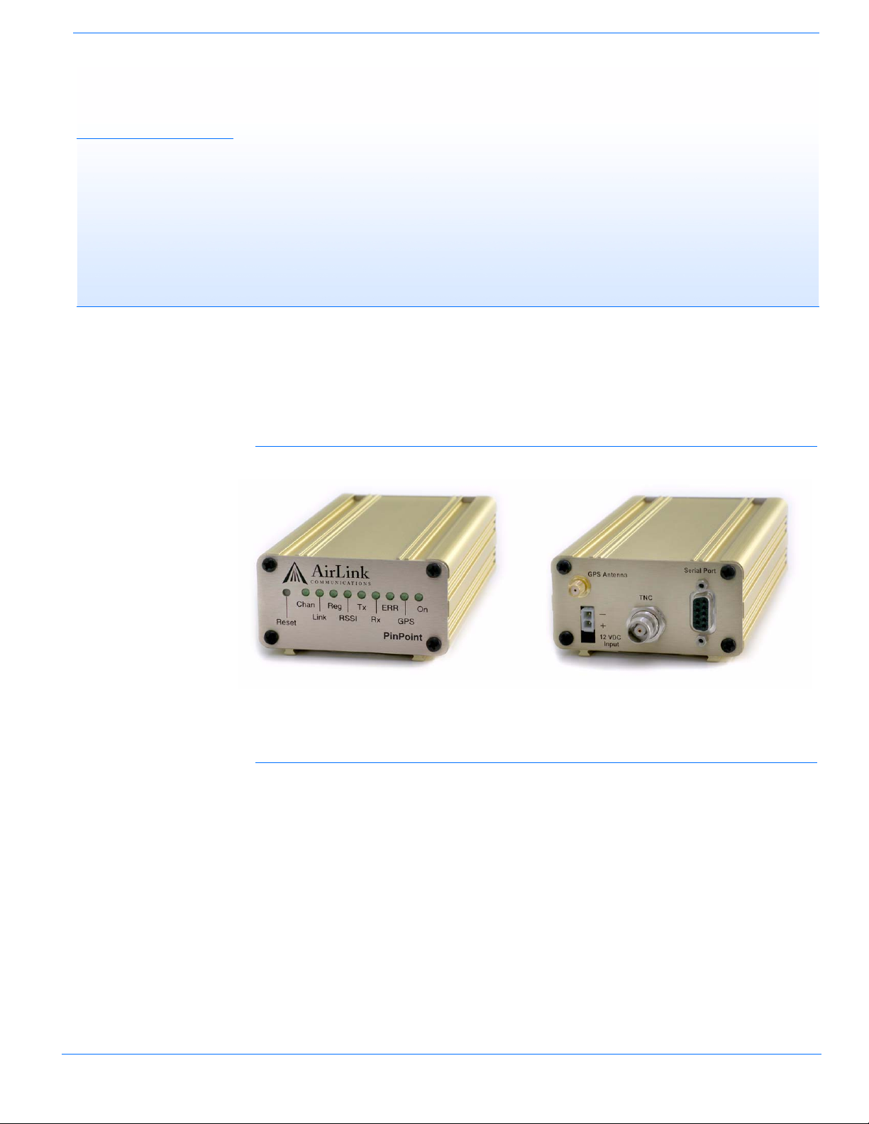
CHAPTER 1 Introduction to PinPoint EDGE/GPRS
The PinPoint's rugged form factor is ideal for industrial and commercial applications that require
real-time communications. The PinPoint provides cellular data communications for a variety of
applications, such as public safety, traffic control, traffic metering, transit arrival systems, and
more.
FIGURE 1. PinPoint front and back
EDGE/GPRS Overview
EDGE (Enhanced Data rates for GSM Evolution) provides end-to-end packet data services with
an enhanced connectivity building on GPRS technology and using the established GSM net
works. EDGE provides higher transmission rates and better transmission quality for data than
GPRS. EDGE can carry data at speeds typically up to 384 kbit/s in packet mode.
When EDGE/GPRS is not available, your PinPoint will fall-back to GPRS for the connection to
Your Wireless Service Provider to provide continued connectivity.
General Packet Radio Service (GPRS) is packet-switched with many users sharing the same
transmission channel, but only transmitting when they have data to send. This means that the total
available bandwidth can be immediately dedicated to those users who are actually sending at any
given moment, providing higher utilization where users only send or receive data intermittently.
GPRS provides speeds of 30–70 kbps with bursts up to 170 kbps.
PinPoint EDGE/GPRS - User Guide, version 2.32 1
-
Page 8

Introduction to PinPoint EDGE/GPRS
Establishing an Internet Connection
The PinPoint uses Your Wireless Service Provider as an ISP (Internet Service Provider) to connect
you to the Internet.
Steps of a connection:
1. When your PinPoint is power ed on, it automat ically searc hes for cellular service using EDGE/
GPRS.
2. Your PinPoint establishes a PPP (Point to Point Protocol or “dial” up connection) link to Your
Wireless Service Provider’ s network, als o called registering on the network, and receives an IP
address.
3. When your PinPoint has received its IP address from Your W ireless Service Provider, then it is
ready to allow you to connect to the Internet.
FIGURE 2. Using the PinPoint to connect to the Internet
Dynamic vs. Static IP Addresses
As stated above, when your PinPoint registers on Your Wireless Service Provider’s network, it
receives an IP address. There are two types of addresses on networks: dynamic and static.
• Dynamic addresses are assigned on a “need to have” basis. Your PinPoint might not always
receive the same address each time it connects with Your Wireless Service Provider.
• Static addresses are permanently assigned to a particular account and will always be used
whenever your PinPoint connects to the Internet. The IP address will not be given to anyone
else.
Most ISPs (cellular included) use dynamic IP addresses rather than static IP addresses since it
allows them to reuse a smaller number of IP addresses for a large number of customers. A
dynamic IP address is suitable for many common Internet uses, such as web browsing, looking up
data on another computer system, or other client functions (such as data only being sent out or only
being received after an initial request).
If you need to contact your PinPoint, a device connected to the modem, or a host system using the
modem from the Internet, you need to have a known IP (such as one which is static) or domain
name (an IP address which is converted by a DNS server into a word based name). If you have a
dynamic IP address for your modem, you can use a Dynamic DNS service (such as IP Manager,
page
14) to translate your IP address into to a domain name.
PinPoint EDGE/GPRS - User Guide, version 2.32 2
Page 9
Introduction to PinPoint EDGE/GPRS
Caution: If you want to connect remotely to your PinPoint using TCP/IP, the IP
address given to your modem by the network cannot be a private or internal IP
address (such as a) unless you are on the same network or inside that network’s
firewall (such as with frame relay).
Using Your PinPoint to Connect to the Internet
In Public Mode, your PinPoint will pass the IP address from Your Wireless Service Provider’s
network to your device or computer. In Private Mode, your modem will assign configured, static
local network IP addresses for the modem and your device.
The modem will perform a one-to-one routing for all internet traffic to and from the computer or
other end device.
If you need to have more than one device connected to the Internet through the modem, you will
need to have a router connected to the modem. The modem would provide the one-to-one con
nection to the router with the router configured to provide a broader NAT service to the other
devices connected to it.
T o use your PinPoint’s serial port to connect to the Internet from your computer, you need to connect the computer directly to the PinPoint’s serial port with a straight-through serial cable and use
Dial-Up Networking (DUN).
-
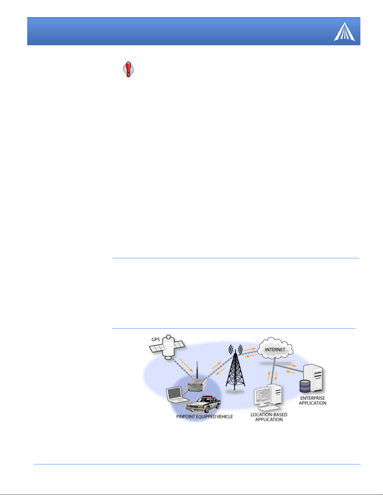
Common Uses for the PinPoint
The PinPoint’s rugged construction and cellular connection make it ideal for use in remote and/or
industrial locations.
Because of its GPS capabilities, the PinPoint is ideal for vehicle tracking and other situations
where mapping a moving object is as important as connecting to a network.
FIGURE 3. Vehicle Tracking and Mobile Internet Access
PinPoint EDGE/GPRS - User Guide, version 2.32 3
Page 10
CHAPTER 2 Activation of the PinPoint
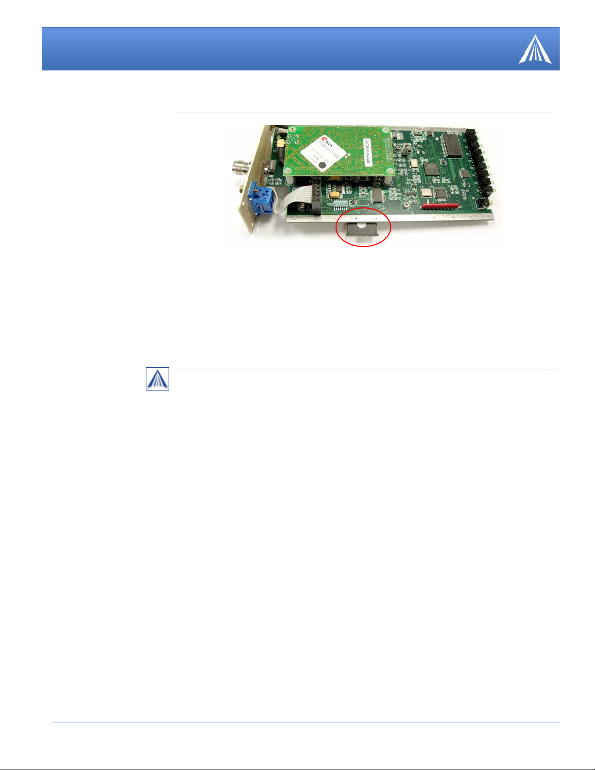
To install the SIM, you will onl y need a small phillips head screw driver.
1.
2.
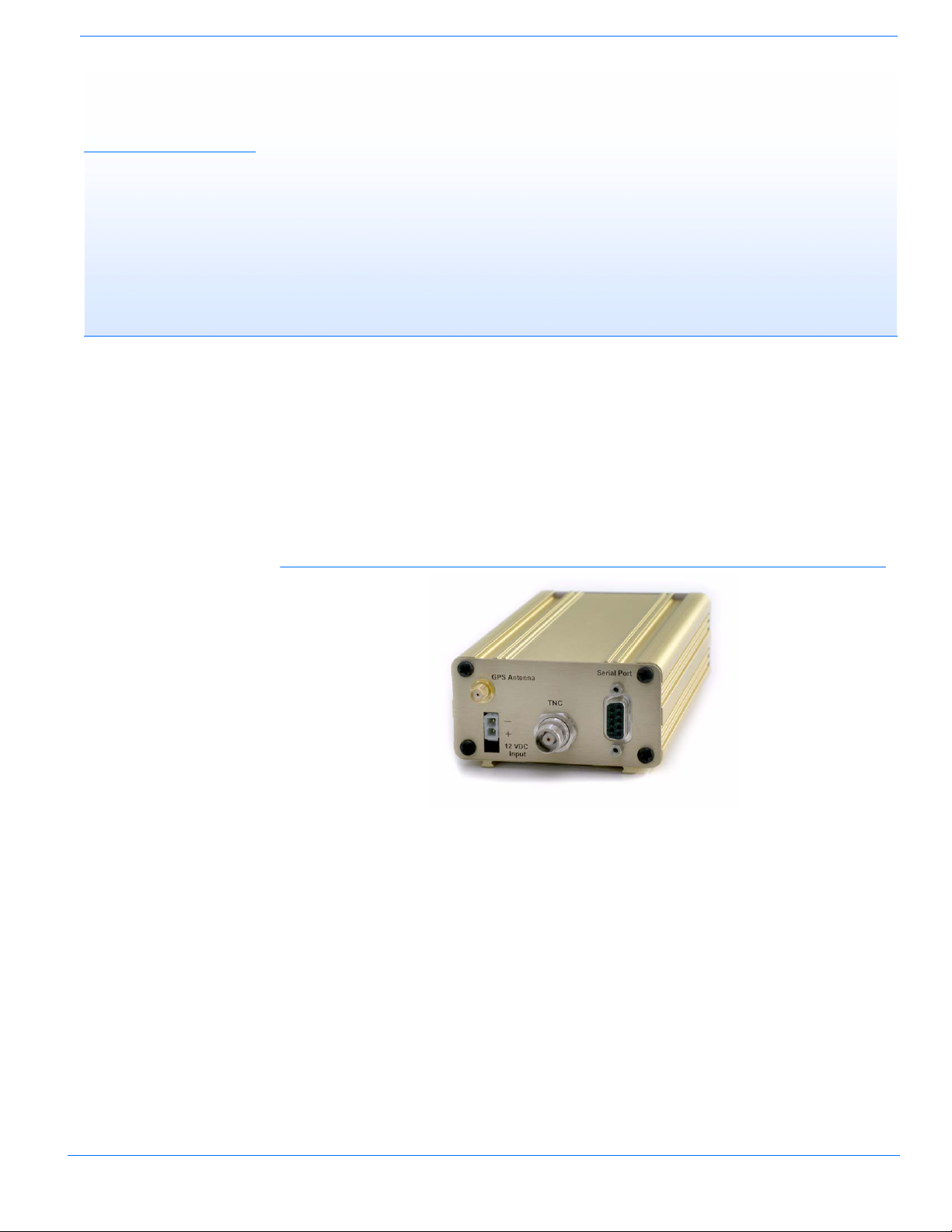
Opening the Case
a. Unplug the PinPoint’s power and all cables.
b. Using a small phillips head screw driver, remove the screws on the back of the PinPoint.
c. Slide the casing off of the PinPoint and set it aside.
FIGURE 1. PinPoint back
Ejecting the SIM tray
a. Using the tip of a PDA stylus, an unbent paperclip, or other slim blunt item press the yellow
button of the SIM tray. On the PinPoint, the button is between two boards.
PinPoint EDGE/GPRS - User Guide, version 2.32 4
Page 11
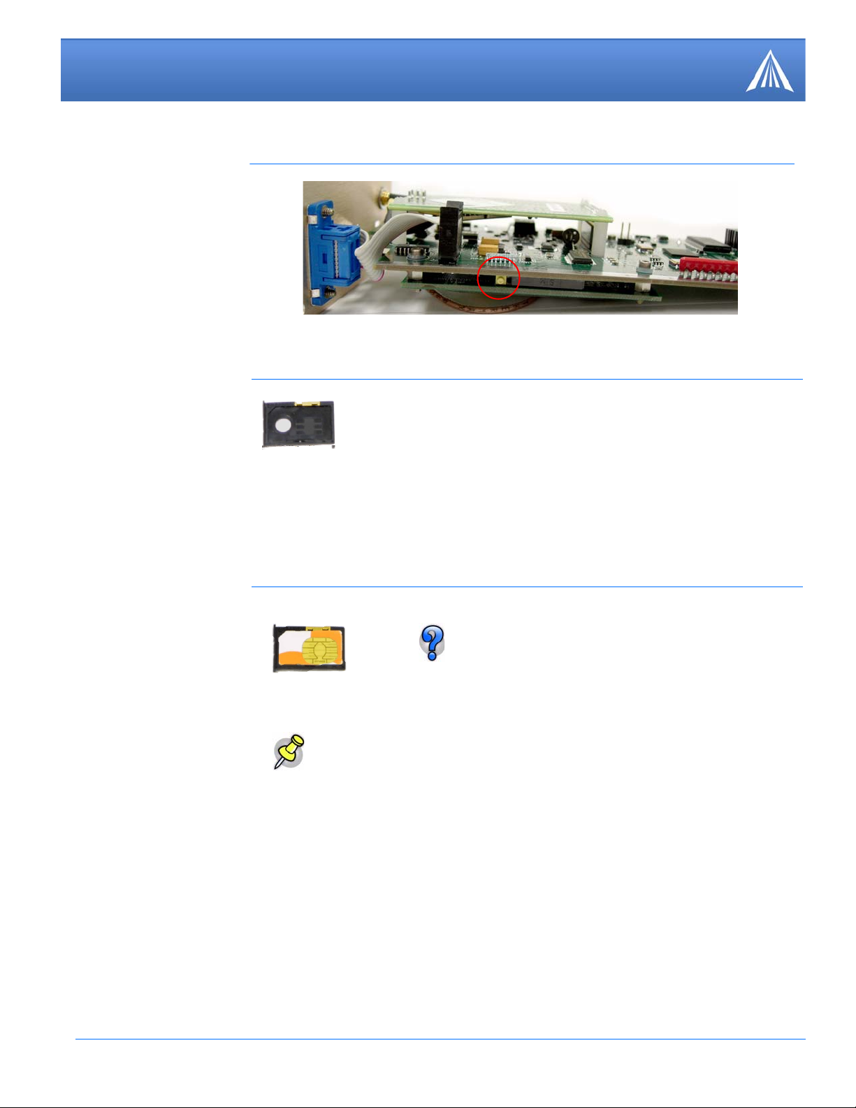
Activation of the PinPoint
FIGURE 2. Tray button: PinPoint
b. Slide the tray out of the slot.
FIGURE 3. Empty SIM Tray
3.
Inserting the SIM
a. Place the SIM into the tray and gently press to click it into place.
FIGURE 4. SIM Tray with a SIM
The SIM may be a different color than this
example.
b. Slide the tray back into the modem and gently press to click it into place.
Note: The top of the card faces the the bottom of the modem.
PinPoint EDGE/GPRS - User Guide, version 2.32 5
Page 12
Activation of the PinPoint
FIGURE 5. Inserting the SIM: PinPoint
4.
1.
2.
Finishing the SIM installation
a. Slide the PinPoint back into the case.
b. Secure the back of the PinPoint with the screws.
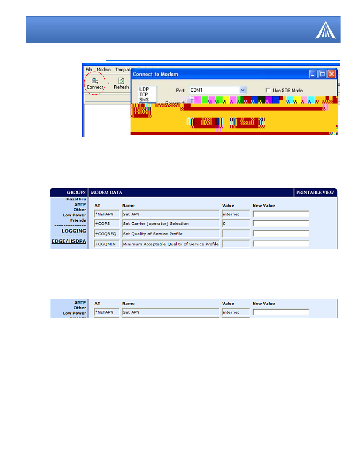
Setting the APN with Wireless Ace
The APN (Access Point Name) is the way your modem knows how it will be communicating with
the network. The APN allows custom IP addressing and tailoring your company's wireless IP solu
tion to meet the security and IP addressing requirements of your applications.
Most EDGE/GPRS accounts use the default addressing solution of Private or Public IP addresses
supplied by the Internet and Proxy APNs. Only if you have a Static or Custom IP address should
you need to configure a custom APNs.
Power on your PinPoint and connect directly to the serial port on your computer.
Start Wireless Ace and connect to your modem:
Start > All Programs > AirLink Communications > Wireless Ace 3G > Wireless Ace 3G
A. Click on Connect.
-
B. Select PPP.
C. Select the COM port to which the modem is connected on your computer (commonly COM1).
D. Type in the modem’s password (default 12345).
PinPoint EDGE/GPRS - User Guide, version 2.32 6
Page 13
Activation of the PinPoint
Internet
FIGURE 6. Wireless Ace: Connect
3.
4.
Select EDGE/HSDPA from the menu on the left side of Wireless Ace (under “Groups”).
FIGURE 7. Wireless Ace: EDGE/HSDPA
Type in the APN in the new value field of *NETAPN.
FIGURE 8. Wireless Ace: *NETAPN
For most EDGE/GPRS accounts the APN for your modem will be Internet or Proxy. Consult
with your account representative on which APN to use.
Optional
PinPoint EDGE/GPRS - User Guide, version 2.32 7
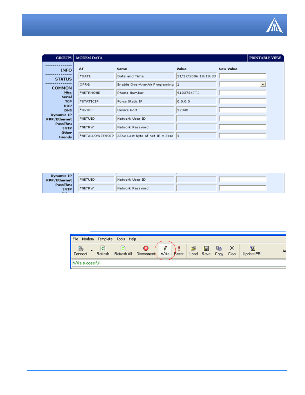
If you need to configure your modem for a custom APN, after entering the APN, there is additional information you will need to enter.
A. Select Misc from the menu on the left side under the Common group.
Page 14
Activation of the PinPoint
[ NAI ]
[ Password ]
FIGURE 9. Wireless Ace: Common - Misc
B. Enter the NAI into the new value field for *NETUID and enter your network password into
the new value field for *NETPW.
FIGURE 10. Wireless Ace: Common - Misc
5.
6.
When you have finished entering the APN settings, click the Write button on the tool bar of Wireless Ace and wait for the message “Write Successful” to appear in the status bar.
FIGURE 11. Wireless Ace: Write
It is recommended that you reset your modem after configuring the APN. Either click the Reset
button in Wireless Ace o-(o)4.9D0ess the reset button on the modem.
PinPoint EDGE/GPRS - User Guide, version 2.32 8
Page 15

CHAPTER 3 Utilities for the PinPoint
AirLink offers a suite of utilities to optimize your PinPoint’s performance, allowing you to
remotely view status and make changes to the configuration as needed.
• AceView • AceNet
• Wireless Ace • Modem Doctor
This section of the PinPoint User Guide covers basic information about these utilities. For additional information on a specific application and how to use it, please refer to the user guide for the
specific utility.
AirLink modem utilities, except AceNet, are free of charge to those who own AirLink modems.
You can download the applications and their user guides from the AirLink web site: http://www.air
link.com/support. Contact your dealer or AirLink representative for information on AceNet.
-
Note: AceV iew, Wireless Ace, and AceNet require the Microsoft .NET Framework
v. 1.1 and Microsoft Windows 98, Windows 2000, Windows XP, or later. You can
obtain the Microsoft .NET Framework from Microsoft at: http://
www.microsoft.com/.
AceView
AceView is a low-profile monitoring tool to view the status of your AirLink PinPoint and display
network status, IP address, RSSI strength, and other basic connection information.
FIGURE 1. AceView
PinPoint EDGE/GPRS - User Guide, version 2.32 9
Page 16
Utilities for the PinPoint
You can connect to your PinPoint locally using a DUN connection or Ethernet across a LAN or
connected directly with a cross over cable. The display is dynamically updated with the current
status of the modem.
The GPS features are available only for PinPoint X, PinPoint-E, and PinPoint modems.
When you use DUN to connect to your PinPoint, AceView can monitor and maintain the DUN
connection.
The DUN connection features are not available with W indows NT or Windows 98. Refer to the
AceView Guide for information on how to connect using serial for Windows NT or Windows
98.
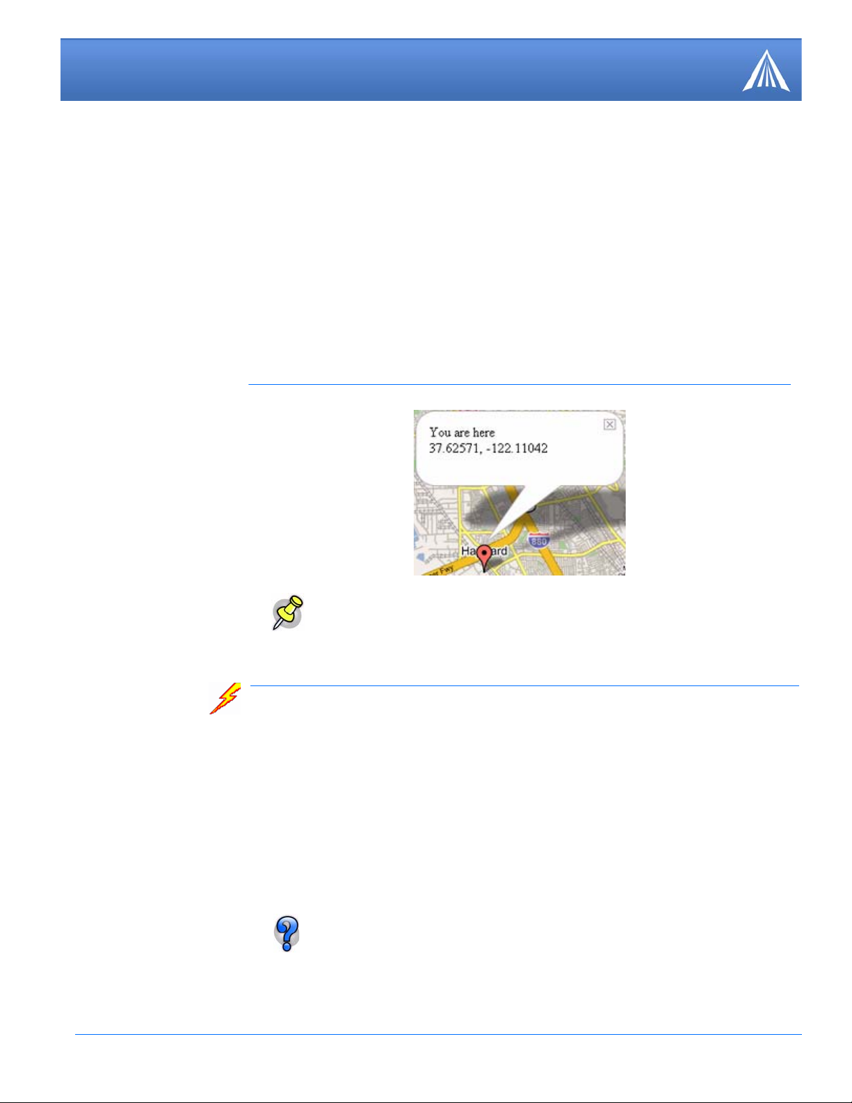
AceView also features a link to a web-based mapping service so you can see where the GPS coordinates locate the PinPoint.
FIGURE 2. Map Coord inates
Note: The mapping feature requires an Internet connection.
Wireless Ace
Wireless Ace enables modems equipped with ALEOS to be monitored and configured locall y or
remotely.
As long as your PinPoint is online and publicly accessible, support personnel can access your
modem from anywhere at any time to see how it is operating and how it is configured. Parameter
changes can be made instantly over-the-air.
Once your modem is configured and installed correctly, a template can be made to program other
modems with the same parameter values. This enables quick, accurate deployment of large pools
of modems.
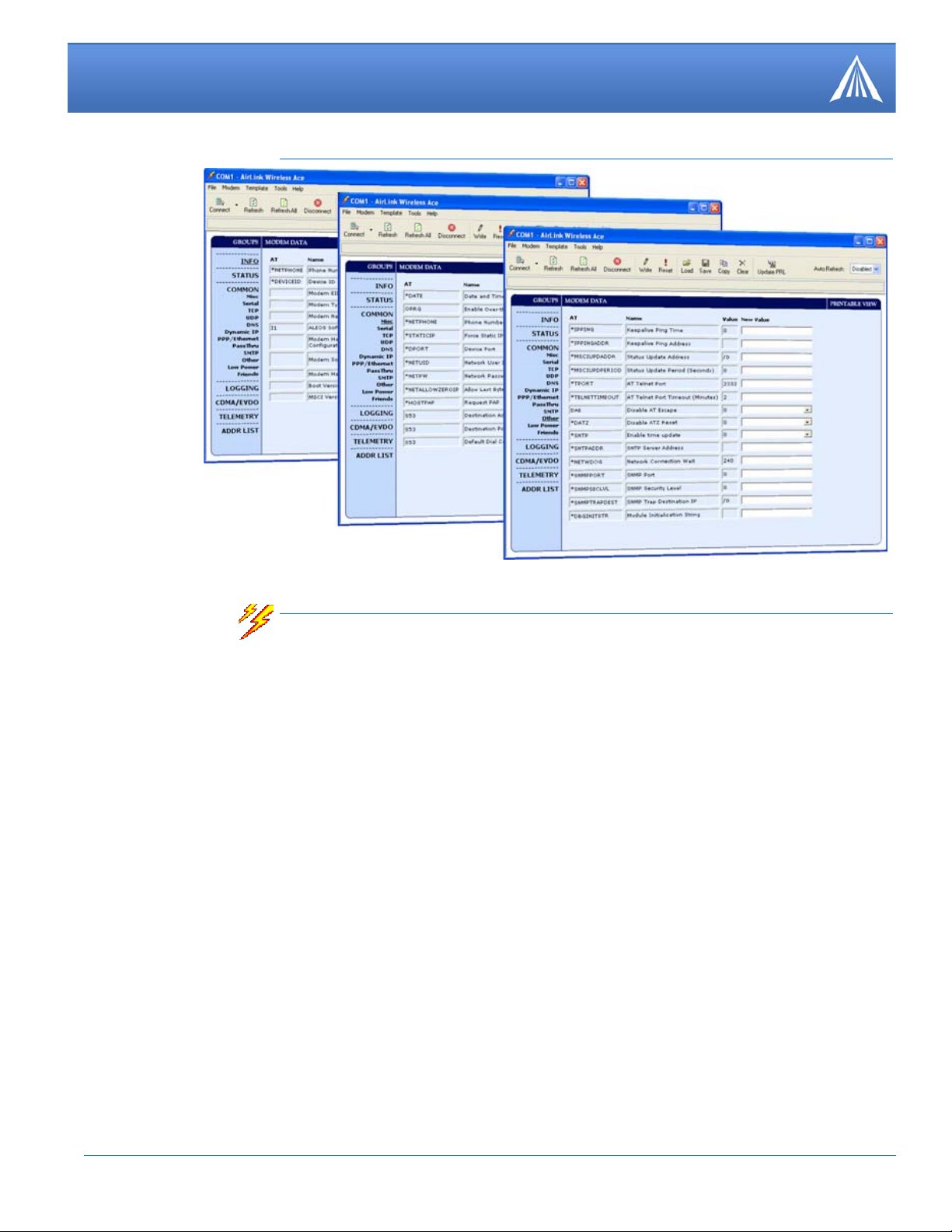
Most configuration screen shots in this guide are using Wireless Ace. Connecting
to the modem using Wireless Ace is covered in the “AT Commands” chapter on
page 59.
PinPoint EDGE/GPRS - User Guide, version 2.32 10
Page 17
Utilities for the PinPoint
FIGURE 3. Wireless Ace
AceNet
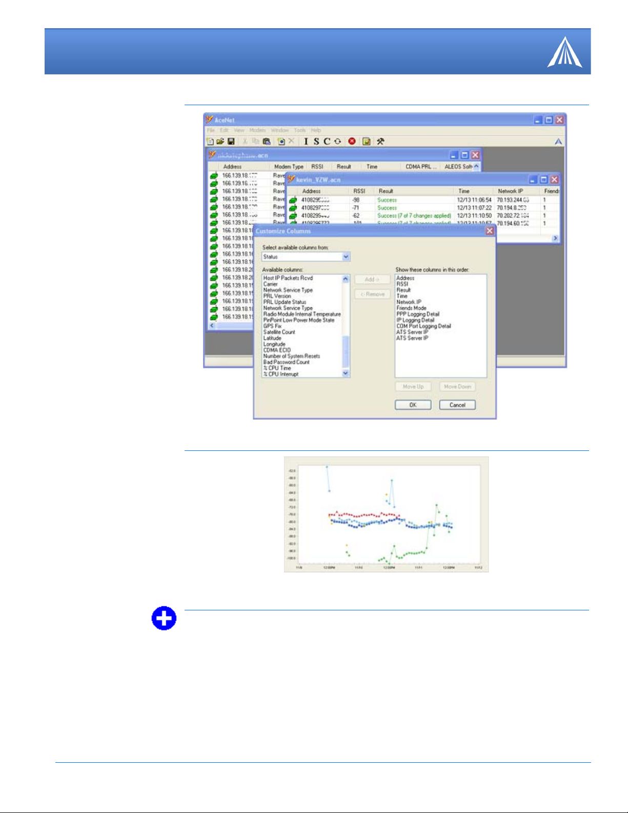
AceNet is a full featured application that you can use to monitor several AirLink modems at the
same time, use a template from Wireless Ace to change the configuration in all of them simulta
neously, keep the modems up-to-date with the latest firmware by updating them over the air, periodically log the modems’ Status parameters, and even graphically chart the logged parameters to
see trends or other over time information.
AceNet’s remote connections use TCP/IP, UDP, or SMS.
AceNet is a separate product which can be purchased from AirLink. Contact your AirLink representative for more information.
-
PinPoint EDGE/GPRS - User Guide, version 2.32 11
Page 18
Utilities for the PinPoint
FIGURE 4. AceNet
FIGURE 5. AceNet Charting
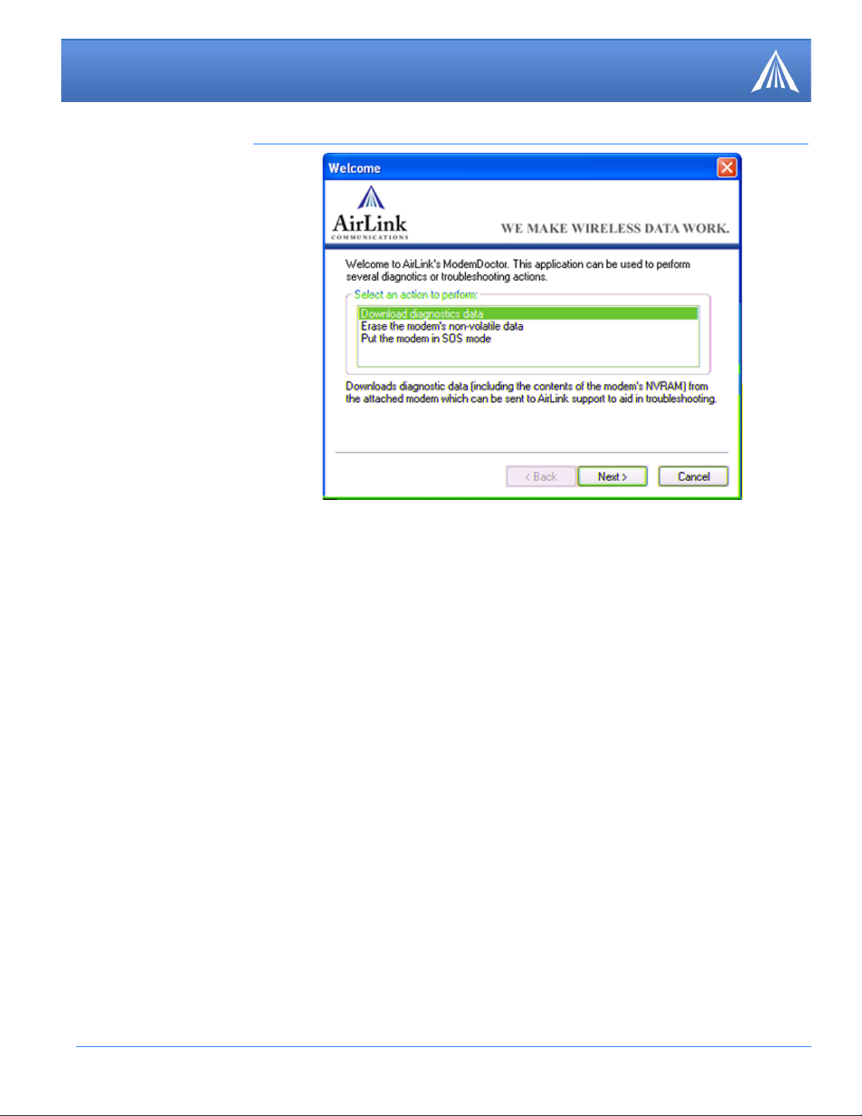
Modem Doctor
Modem Doctor is a troubleshooting and diagnostics utility. This utility will allow you to get a log
file of the
ration completely, and temporarily set the PinPoint to a known configuration to aid in trouble
shooting (SOS mode).
PinPoint activity which you can then send to AirLink support, erase the current configu-
PinPoint EDGE/GPRS - User Guide, version 2.32 12
Page 19
Utilities for the PinPoint
FIGURE 6. Modem Doctor
PinPoint EDGE/GPRS - User Guide, version 2.32 13
Page 20

CHAPTER 4 IP Manager and DNS
If you have a fleet of AirLink modems or even if you only have one, it can be difficult to keep track
of the current IP addresses, especially if the addresses aren’t static but change every time the
modems connect to Your Wireless Service Provider. If you need to connect to a modem, or the
device behind it, it is so much easier when you have a domain name (car54.mydomain.com, where
are you?).
Reasons to contact the modem and/or the connected device:
• Requesting a location update from a delivery truck.
• Contacting a surveillance camera to download logs or survey a specific area.
• Updating advertisements to be displayed in a cab.
• Monitoring and troubleshooting the status of the modem itself without needing to bring it in or
go out to it.
A dynamic IP address is suitable for many Internet activities such as web browsing, looking up data
on another computer system, data only being sent out, or data only being received after an initial
request (also called Mobile Originated). However, if you need to contact your PinPoint directly, a
device connected to the modem, or a host system using your PinPoint (also called Mobile Termi
nated), a dynamic IP won’t give you a reliable address to contact (since it may have changed since
the last time it was assigned).
Domain names are often only connected to static IP addresses because of the way most domain
name (DNS) servers are set-up. Dynamic DNS servers require notification of IP Address changes
so they can update their DNS records and link a dynamic IP address to the correct name.
-
• Dynamic IP addresses are granted only when your PinPoint is connected and can change each
time the modem reconnects to the network.
• Static IP addresses are granted the same address every time your PinPoint is connected and are
not in use when your PinPoint is not connected.
Since many cellular providers, like wire-based ISPs, do not offer static IP addresses or static
address accounts cost a premium vs. dynamic accounts, AirLink developed IP Manager to work
with a Dynamic DNS server to receive notification from AirLink modems to translate the modem’s
dynamic IP address to a fully qualified domain name. Thus, you can contact your PinPoint directly
from the Internet using a domain name.
PinPoint EDGE/GPRS - User Guide, version 2.32 14
Page 21

IP Manager and DNS
Fully Qualified Domain Name
A domain name is a name of a server or device on the Internet which is associated with an IP
address. Similar to how the street address of your house is one way to contact you and your phone
number is another, both the IP address and the domain name can be used to contact a server or
device on the Internet. While contacting you at your house address or with your phone number
employ different methods, using a domain name instead of the IP address actually uses the same
method, just a word based name is commonly easier to remember for most people than a string of
numbers.
Understanding the parts of a domain name can help to understand how IP Manager works and what
you need to be able to configure the modem. A fully qualified domain name (FQDN) generally has
several parts.
• Top Level Domain (TLD): The TLD is the ending suffix for a domain name (.com, .net, .org,
• Country Code Top Level Domain (ccTLD): This suffix is often used after the TLD for most
• Domain name: This is the name registered with ICANN (Internet Corporation for Assigned
• Sub-domain or server name: A domain name can have many sub-domain or server names
etc.)
countries except the US (.ca, .uk, .au, etc.)
Names and Numbers) or the registry for a the country of the ccTLD (i.e. if a domain is part of
the .ca TLD, it would be registered with the Canadian domain registry). It is necessary to have
a name registered before it can be used.
associated with it. Sub-domains need to be registered with the domain, but do not need to be
registered with ICANN or any other registry. It is the responsibility of a domain to keep track
of its own subs.
car54.mydomain.com
• .com is the TLD
• mydomain is the domain (usually noted as mydomain.com since the domain is specific to the
TLD)
• car54 is the subdomain or server name associated with the device, computer, or modem regis-
tered with mydomain.com
car54.mydomain.com.ca
This would be the same as above, but with the addition of the country code. In this example, the
country code (.ca) is for Canada.
A URL (Universal Resource Locator) is different from a domain name in that it
also indicates information on the protocol used by a web browser to contact that
address, such as http://www.airlink.com. www.airlink.com is a fully qualified
domain name, but the http://, the protocol identifier, is what makes the whole thing
a URL.
PinPoint EDGE/GPRS - User Guide, version 2.32 15
Page 22
IP Manager and DNS
car54-2007
eairlink.com
edns2.eairlink.com
eairlink.com
Dynamic Names
When an IP address is not expected to change, the DNS server can indicate to all queries that the
address can be cached and not looked up for a long period of time. Dynamic DNS servers, con
versely, have a short caching period for the domain information to prevent other Internet sites or
queries from using the old information. Since the IP address of a modem with a dynamic account
can change frequently, if the old inform atio n was used ( su ch as w ith a DNS server which indicates
the address can be cached for a long period of time) when the IP address changed, the domain
would no longer point to the new and correct IP address of the modem.
If your PinPoint is configured for Dynamic IP, when it first connects to the Internet, it sends a IP
change notification to IP Manager. IP Manger will acknowledge the change and update the
Dynamic DNS server . The new IP address will then be the address for your PinPoint’s configured
name.
Once your PinPoint’s IP address has been updated in IP Manager, it can be contacted via name. If
the IP address is needed, you can use the domain name to determine the IP address.
-
Note: The fully qualified domain name of your PinPoint will be a subdomain of the
domain used by the IP Manager server.
Configuring the PinPoint for IP Manager and a Dynamic IP Domain Name
To configure the Dynam ic IP settings in your PinPoint so that it will use IP Manager, you can use
Wireless Ace or a terminal application to enter the commands (page
To configure your AirLink modem to be addressed by nam e , the modem needs to have 4 elements
configured. Y ou can configure a second dynamic server as a backup, secondary , or alternate server .
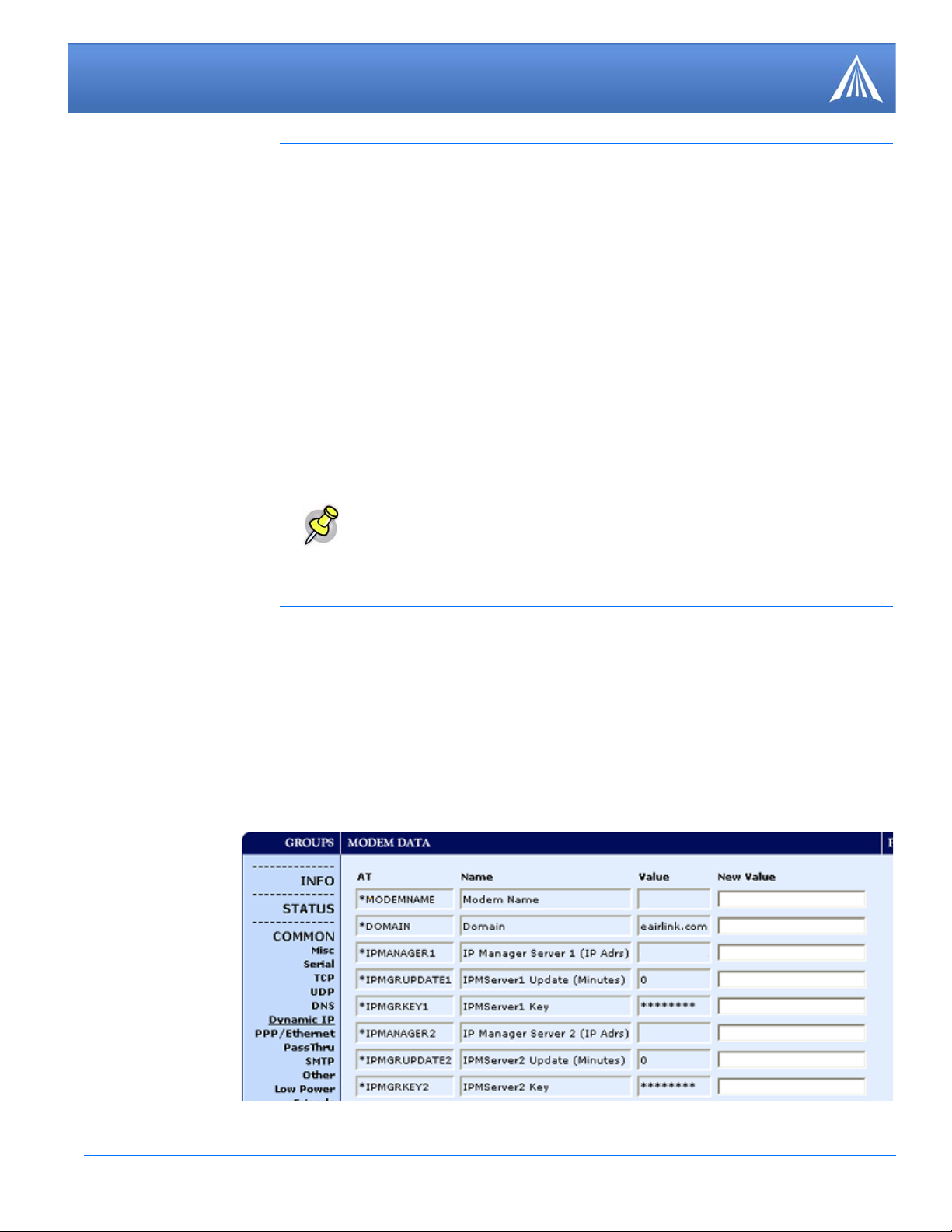
In Wireless Ace, select Dynamic IP.
FIGURE 1. Wireless Ace: Dynamic IP
59).
PinPoint EDGE/GPRS - User Guide, version 2.32 16
Page 23

IP Manager and DNS
Restrictions for Modem Name
For the Modem Name, you should use something which is unique but also easy to remember. Your
company name or the intended function of the modem are recommended. If you have more than
one modem and want to name them the same, you can append a number for each. Since it is an
Internet domain name, there are some restrictions for the name.
*MODEMNAME: The name you want for the modem.
*DOMAIN: The domain name to be used by the modem.
*IPMANAGER1 and *IPMANAGER2: The IP address or domain name of the dynamic DNS
server which is running IP Manager.
Note: To use the name here instead of the IP, you need to have DNS set up in your
PinPoint (page
*IPMGRUPDATE1 and *IPMGRUPDATE2: How often, in minutes, you want the address
sent to IP Manager. If this is set to zero, the modem will only send an update if the IP address
changes (example, if your PinPoint modem is reset or is assigned a different IP address).
*IPMGRKEY1 and *IPMGRKEY2: User defined password key which is used instead of AirLink secret key when using an IP Manager server other than the one provided by AirLink.
18).
• Must begin with a letter or number
• Can include a hyphen (-)
• Cannot contain spaces
• Must be no longer than 20 characters total
Data Usage for IP Manager Server Updates
The IP Manager update is a small packet sent to the server with a response sent back to the modem.
If you have *IPMGRUPDATE1 or *IPMGRUPDATE2 set to any number but zero, the modem
will send the update not only when it receives a new IP address but at the time interval as well. The
data traffic could be billed by your carrier.
Each update is a total of 68 bytes from the modem with a 50 byte total response from the server for
a round trip update of 118 bytes.
Eairlink.com
As a service, Airlink maintains a IP Manager servers which can be used for any AirLink modem.
• *DOMAIN: eairlink.com
• *IPMANAGER1 : edns2.eairlink.com
• *IPMANAGER2 : eairlink.com
PinPoint EDGE/GPRS - User Guide, version 2.32 17
Aotper
Page 24
IP Manager and DNS
DNS: Using Names Instead of IP addresses
The PinPoint has the ability to query DNS servers in order to translate domain names into IP
addresses. This allows you to use domain names in place of IP addresses for most of the configu
ration options requiring IP addresses. This is important if your PinPoint will need to contact
another modem or other device that has a domain name but an unknown or dynamic IP address
(such as another remote PinPoint using IP Manager).
Configuring DNS
Generally, when your PinPoint receives its IP address from Your W ireless Service Provider, it will
also receive Your Wireless Service Provider’s DNS servers to use for resolving (or translating)
names to IP addresses which it will automatically configure in the modem settings. Unless your
PinPoint will be used on a network with other modems or devices which have names internal to the
local network or frequently changing IP addresses, the DNS servers provided by Your Wireless
Service Provider should be all you need.
Note: The IP Manager service from AirLink is currently not a guaranteed service
though every effort is made to keep it operational 24/7.
When using AirLink’s IP Manager servers, since there are many AirLink modems
using the service, it is even more imperative to have a unique name for your
modem.
-
If the PinPoint will be communicating with a device that has a domain name but changes its IP
address frequently (such as another AirLink modem using IP Manager) or is on a network where
devices are accessed by names rather than IP addresses, you will want to put in an alternate DNS
(*DNSUSER) where that domain is updated, such as the IP Manager server the remote modem is
using or the listing of IP addresses to names is kept.
FIGURE 2. Wireless Ace: DNS
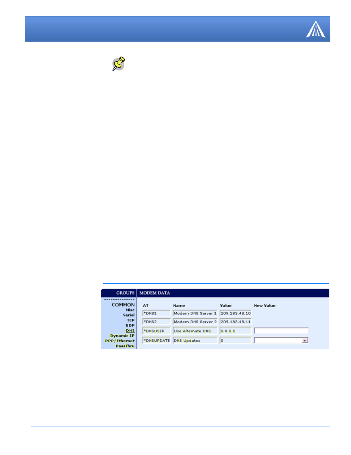
*DNS1 and *DNS2 - The primary and secondary DNS servers set by Your Wireless Service
Provider when your PinPoint gets its IP address.
*DNSUSER - Set this, if desired, to an additional DNS server to query first before the primary
or secondary (just as a hosts file is queried first on a computer). If *DNSUSER is set to 0.0.0.0,
it will be ignored.
*DNSUPDATE - This command sets how often you want DNS Updates to be requested. Otherwise the PinPoint will only send updates when it is reset, powered up, or the IP address is
granted by network changes.
PinPoint EDGE/GPRS - User Guide, version 2.32 18
Page 25

IP Manager and DNS
PPP-Peer
The PinPoint use the unqualified domain name of “ppp-peer” when it is in PPP or SLIP address
mode to resolve the address of the device or computer connected via PPP or SLIP address. If the
PinPoint is not in PPP or SLIP address mode, “ppp-peer” will resolve to 0.0.0.0.
Note: If you will be using your PinPoint to communicate with another AirLink
modem and both are using IP Manager to translate dynamic IP addresses to
domain names, it is recommended that you set *DNSUSER to the IP address for
IP Manager. IP Manager’s updates occur more frequently than Your Wireless Ser
vice Provider’s DNS servers decreasing the time between IP address change and
address resolution. Likewise, if your PinPoint routinely needs to contact another
modem or device with a Dynamic DNS domain and that modem or device fre
quently changes its IP address, you may need to set *DNSUPDATE for frequent
updates.
-
-
PinPoint EDGE/GPRS - User Guide, version 2.32 19
Page 26

CHAPTER 5 Data Communication and Host Modes
The PinPoint plays the part of a HOST when a computer or another device is connected to its
serial or Ethernet port. The PinPoint can also route data to/from the connected device to the cellular network.
Note: The PinPoint moves data from one port to the cellular network in a simple
one-to-one routing. It does not employ a routing table or any complicated routing
protocol. If you need to have one-to-many routing, you can connect the
PinPoint to
a router. The router would provide the multiple routing and the PinPoint would
provide one-to-one for the router to the cellular network and the Internet.
As the host, the PinPoint can use different communication modes.
AT: The PinPoint accepts and responds to standard AT commands.
PassThru: Direct connection to internal hardware (OEM Module) of the PinPoint.
Telnet: The PinPoint auto-answers TCP connections to allow terminal emulation using the cellu-
lar connection.
PPP Mode: The PinPoint uses PPP to communicate with a device or computer connected to the
serial port.
SLIP Mode: The PinPoint uses SLIP to communicate with a device or computer connected to the
serial port.
UDP and UDP PAD: Any data received on the serial port is assembled into UDP packets and sent
to the session’s associated IP address and Port (described later). Any responses received from the
associated IP address and port destined for the modem's Device Port are unwrapped and sent out
the serial port.
TCP and TCP PAD: Any data received on the serial port is packaged into TCP messages and
sent to the associated connection’s IP address and Port (described later). Any data received from
the TCP peer is unwrapped and sent out the serial port.
By default, the PinPoint is in AT Mode and allows AT Commands to be entered via terminal connection (through the local port connection) or remotely (through the cellular network). PassThru
Mode can only be exited by resetting the PinPoint. All other modes are entered by use of a startup
mode command.
PinPoint EDGE/GPRS - User Guide, version 2.32 20
Page 27
Data Communication and Host Modes
The serial port of the PinPoint can be configured to enter any of the modes automatically on
power up (in most cases, this is also after it has registered on the cellular network). This is done
by setting the Startup Mode Default (refer to MD in the AT Command listing, page
desired mode. If this setting is non-zero, the modem will enter the specified mode after 5 seconds.
If you want to cancel this behavior, the ATMD0 command can be used before the 5-second timeout expires.
FIGURE 1. Wireless Ace: MD
87) to the
If the PinPoint is in any mode other than AT or PassThru, the AT command mode can be reentered by:
• Deactivating DTR (if &D2 or Ignore DTR, S211, is not set).
• Issuing the +++ escape sequence (if Disable AT Escape, DAE, is not set).
• Resetting or Power cycling the modem.
Note: DTR needs to be asserted (S211=1 or &D0) by the host before PPP Mode,
SLIP Mode, UDP PAD Mode, or TCP PAD Mode can be entered.
AT Mode
Using a terminal connection, AT commands are used to configure the modem, command it to do
something, or query a setting. For a full listing of the AT commands, refer to page
Ace is a graphical user interface for most AT Commands.
AT commands must always be terminated by <CR> (ASCII character 0x0D), a carriage return
(pressing enter on the keyboard). Some may also include a new line or line feed <LF>.
If E=1 (Echo On), the AT command (including the terminating <carriage return) will be displayed (output) before any responses.
59. Wireless
Two settings affect the format of AT command output: V (Verbose) and Q (Quiet).
PinPoint EDGE/GPRS - User Guide, version 2.32 21
Page 28
Data Communication and Host Modes
If Q=1 (Quiet On), no result codes are output whatsoever, so there is no response generated by
a (non query) command.
If Q=0 (Quiet Off), result codes are output. The format of this output is then affected by the
Verbose setting.
If Quiet mode is off, the result code is affected as follows:
For V=1 (Verbose mode), the textual result code is surrounded by a carriage return and new
line. Any AT query response is also surrounded by a carriage return and new line.
For V=0 (T erse mode), a numeric result code is output with a single trailing carriage return (no
new line is output), while any AT query response is followed by a carriage return and new line
(there is no preceding output).
For example, possible output to the AT command "AT" with carriage return (assuming quiet mode
is not on) is:
carriage return - if V=0
carriage return and new line OK another carriage return and new line - if V=1
PassThru Mode
In PassThru mode, the PinPoint does not behave normally, all port communication is passed
directly between the internal hardware and the computer connected directly to the modem. This
mode can be used to configure hardware-specific settings (for example, provisioning, trouble
shooting, etc.).
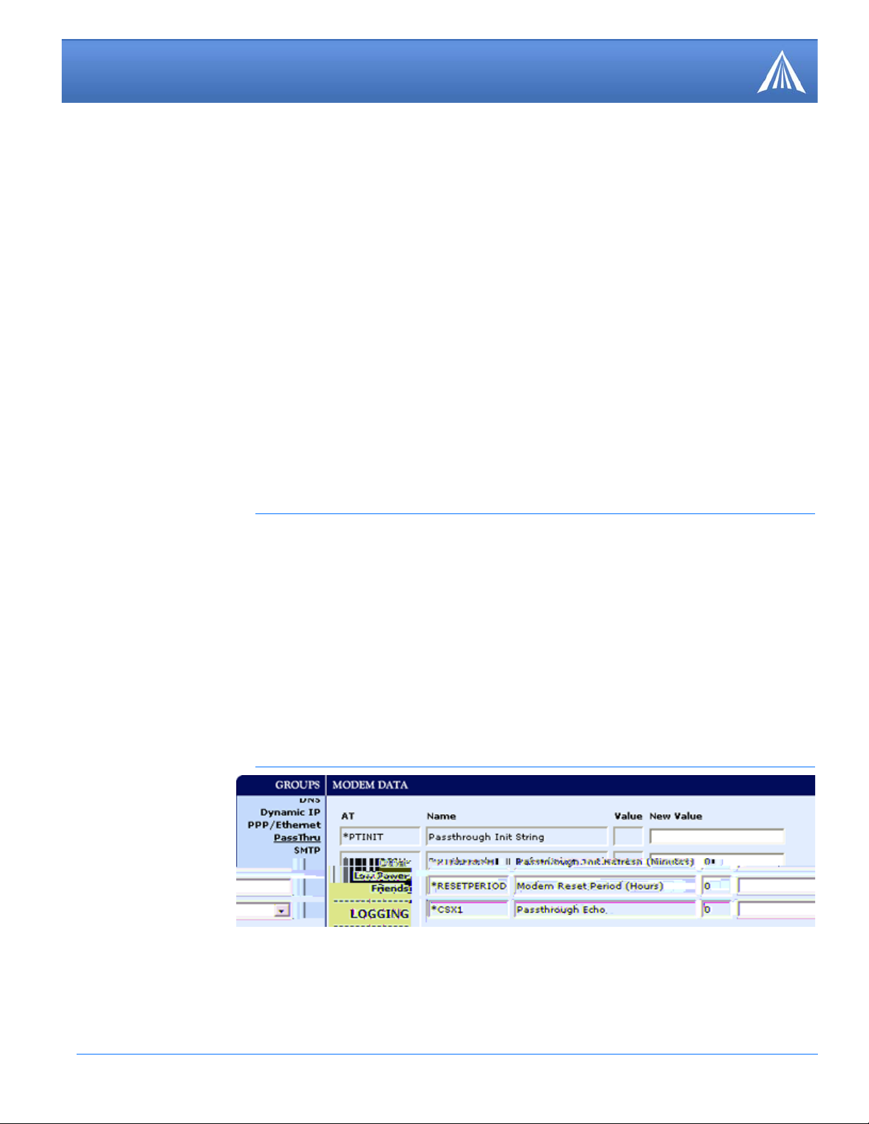
Issuing the "AT\APASSTHRU" from a terminal emulation enters this mode. The modem responds
with OK, at which point a direct connection to the internal hardware is established.
With Wireless Ace, you can configure a string of AT commands to be sent to the PinPoint when it
enters PassThru and other PassThru settings.
FIGURE 2. Wireless Ace: PassThru
-
You can configure MD to have the PinPoint enter PassThru on start up.
PinPoint EDGE/GPRS - User Guide, version 2.32 22
Page 29
Data Communication and Host Modes
FIGURE 3. Wireless Ace: MD
Some internal hardware requires upwards of 20 seconds before AT commands can be entered, so
be patient if there seems to be no response to AT commands.
Caution: PassThru can only be exited by resetting or power-cycling the modem.
This mode cannot be entered via a remote Telnet session.
PassThru Mode allows only specific AT commands. Some ALEOS commands will be unavailable
when the modem is in PassThru mode. The commands usable also depend heavily on the modem
model number (found on the label on the top of the modem).
Caution: ALEOS is disabled in PassThru Mode. You cannot use most ALEOS
specific commands while the modem is in PassThru Mode. While in PassThru
mode, you also cannot use Wireless Ace to connect with the PinPoint.
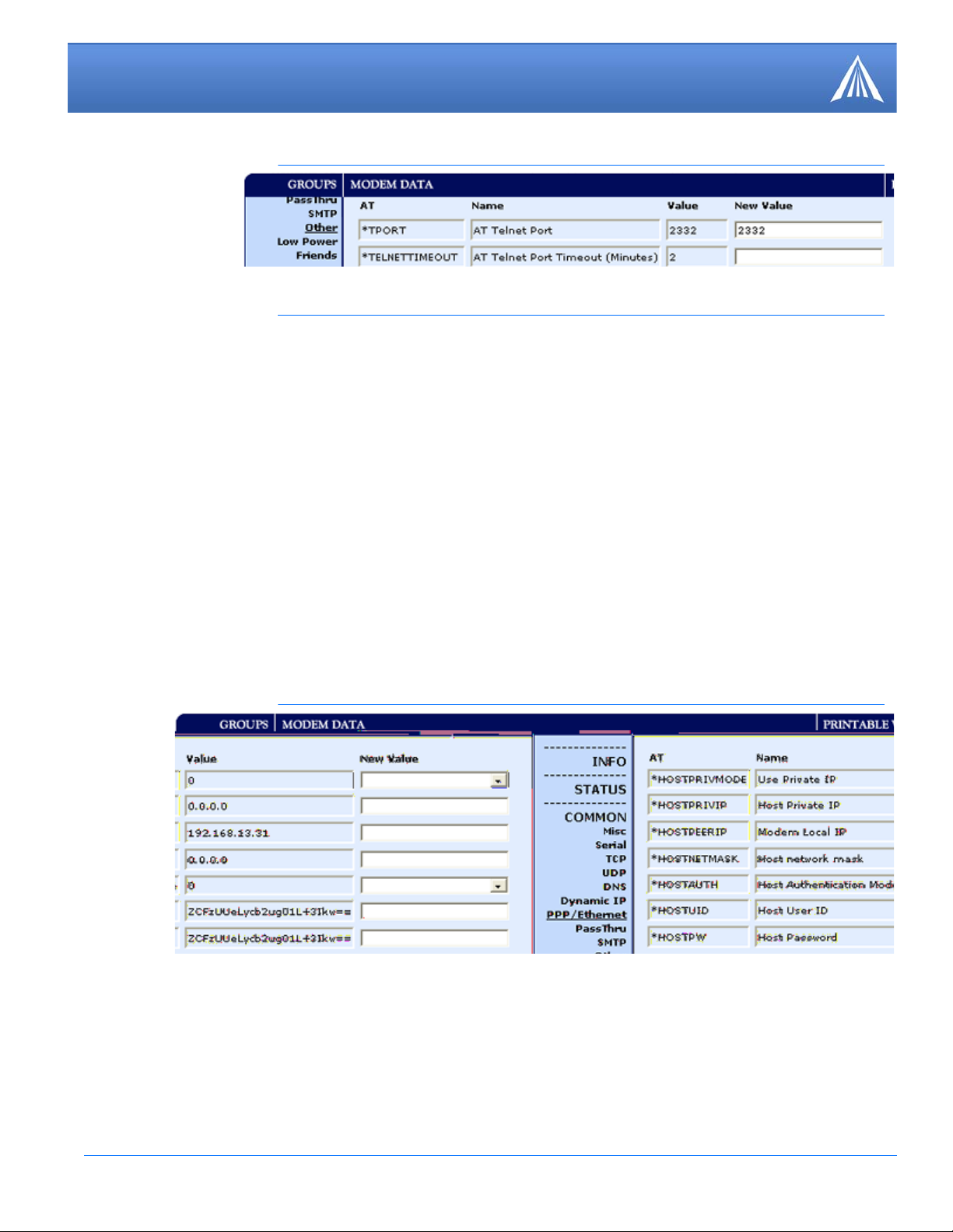
TelnetMode
In Wireless Ace you can configure Telnet operation.
FIGURE 4. Wireless Ace: Telnet Configuration
If you need to change the port for Telnet (for example, you have the default port blocked on your
firewall), the option is on the Other tab. The default telnet port is 2332. You can also change the
T elnet timeout, if the connection is idle, default 2 minutes.
PinPoint EDGE/GPRS - User Guide, version 2.32 23
Page 30
Data Communication and Host Modes
FIGURE 5. Wireless Ace: Telnet Configuration
PPP Mode
In PPP mode, the PinPoint acts as a PPP server, providing an IP address, and DNS servers (if
available) to the Host. PPP mode is entered from the AT mode by using any of the following com
mands:
AT\APPP
ATDT10.0.0.1
ATDT10001
ATD*99***1#
CLIENT
-
In response to any of the preceding commands, the modem will respond with CONNECT a carriage return and new line and is ready for the host to begin PPP negotiations. The IP received by
the host in the resulting negotiation will either be a private (non-routable) IP address or a public
(network-routable) IP address provided by the network, depending on the settings of *HOST
PRIVMODE. If *HOSTPRIVMODE=1, the value of the private IP address can be determined
beforehand by querying S110. The private IP address to be used can be defined with the command
AT*HOSTPRIVIP=192.168.100.33 substituting the desired IP address.
FIGURE 6. Wireless Ace: PPP/Ethernet
Using a private IP insulates the PPP client from changes in IP addresses of the underlying network. The will perform basic NAT-like address translation on all packets.
If a public IP address is being used, any changes in the IP (as determined by the wireless network)
will result in the PPP link to the host being disconnected, requiring the host to reinitiate it. The
public IP is passed to the host in the PPP negotiations, so when the network forces a change, the
modem has to force the host to renegotiate the PPP link to make this happen.
PinPoint EDGE/GPRS - User Guide, version 2.32 24
Page 31

Data Communication and Host Modes
Slip Mode
SLIP mode is entered be using the "AT\ASLIP" command. As in PPP Mode, the IP address that
the host assumes is affected by the setting of *HOSTPRIVMODE. SLIP does not negotiate the
IP with the host, so before making a SLIP connection, the host SLIP driver must be configured to
use the IP specified by querying S110.
UDP Pad
When the modem is in UDP PAD (Packet Assembly and Disassembly) Mode, all characters
received on the seial port are assembled into UDP packets and sent to the PinPoint’s remote IP
address/port, and any packets received from the same IP/port-destined for the PinPoint’s device
port (see *DPORT)--are disassembled and dumped onto the serial line.
A UDP session is initiated by one of the following events:
• Using the Dial UDP (DP) AT command (example, ATDP192.168.3.23/3456).
• Setting the Startup Mode Default (MD) to 3 (UDP) so that a UDP session is entered automati-
cally when the modem registers onto the network. Serial data will be sent to the IP/port specified in S53.
• Incoming UDP packets will be processed out the serial port if
• UDP auto answer is enabled (S82=2);
• The destination IP address matches that in S53 (if Friends Mode is enabled, the IP address
also needs to be present on the Friends List);
• Or allow any IP is set (AIP=1);
• The modem is in AT mode (not in a current UDP or TCP session).
UDP packet assembly is affected by the values of S50 (PAD Forwarding Time-out) and S51 (P AD
Forwarding Character). Data received in the serial buffer will be transmitted when the idle intercharacter time-out specified in S50 (in tenths of seconds) occurs or when a character is received
that matches S51 (if non-zero).
UDP Auto Answer
UDP auto answer (previously called UDP half-open) is set with S82=2. When set, the PinPoint
will automatically establish a UDP session to the source IP address and port of the UDP packet
received. The PinPoint will remain "locked" to this one remote IP/port until no data is sent or
received for the time interval defined in the UDP auto answer time-out (S83). During this session,
packets from other IP/port addresses will be rejected, unless *UALL is set. Whether or not an
incoming packet will cause the modem to enter a UDP session is always dependent on the S53
and AIP settings.
The Normal UDP Mode (MD3) can be combined with UDP auto answer to cause the incoming
serial data to be sent in UDP packets (instead of being treated as AT commands), while allowing
sessions to be established from different UDP sources. A UDP session will be initiated either by
incoming serial data or by an incoming UDP packet. The session, started by either method, will
be terminated when no data has been sent or received for the S82 period. Once the session termi
nates, another may be initiated by either means.
PinPoint EDGE/GPRS - User Guide, version 2.32 25
-
Page 32

Data Communication and Host Modes
When idle, after the time-out has occurred, the modem is in A T command mode on the serial port,
and any valid AT command may be entered during this time.
Note: It is best to ensure the idle time-outs for TCP and UDP are never 0 if you're
going to be using auto-answer, or either PAD mode. In those circumstances, you
will want the modem to close the socket if the connection goes idle for too long,
particularly if the other side doesn’t normally close the connection.
When the session is initiated by serial data, the new session will be established using the destination address specified in S53. The S53 setting can be changed if the connect to last UDP setting
(*UDPLAST=1) is set. The address in S53 will be updated to reflect the address of the last ses
sion initiated by an incoming UDP packet. So that when new data is received over the host serial
port while in the idle state, a session will be re-established with the last address. (This behavior is
the same as the previous Hybrid2 (MD6) mode).
Note: TCP auto answer (S0) may also be set simultaneously with UDP auto
answer. Then, when in the idle state, the modem will accept either a TCP or UDP
incoming packet, and enter a TCP or UDP session as appropriate.
Reliable UDP
-
Reliable UDP adds a simple protocol on top of UDP to provide reliable delivery of data. When
data is received from the host serial port, a 2 byte header is added to the data, containing a mes
sage type and a sequence number. The PinPoint will continue to send this data (buffering any
received data in the meantime) until it receives an acknowledgement with this sequence number.
If an acknowledgement is not received within the time-out period (specified in S7), the data will
be retransmitted. This will continue until an acknowledgement is received or the modem is reset.
Likewise any UDP packets received by the PinPoint are expected to have this simple header. The
PinPoint will issue an acknowledgement for any valid packets which are received.
T o configure the PinPoint for a normal UDP session, you need to set the Startup Mode Default to
73 (ATMD73). If you are using two modems, configure the Destination IP and Port in each to
point to each other. Serial data will then be sent reliably between the two.
Note: Although it adds reliability, the simple implementation of the Reliable UDP
mode in the does not check for duplicate packets.
-
UDP Multicast Mode
UDP Multicast mode results in any data received from the host serial port being sent to all the clients in the address list. The remote port number is taken from S53. To avoid flooding the network,
the packets are sent to each client with a 20ms pause in between. The receipt of UDP packets
works as in normal UDP mode (i.e. bound by the value S53 and/or AIP). Since it may take a while
to transmit the data to all hosts (especially if all 20 Modbus entries are used and name resolutions
are required), new data received from the host port is buffered until current transmissions to all
hosts are finished.
Enter the list of target IPs in the address list (ADDR LIST). The index numbers in the list aren't
used. Configure for a normal UDP session. Set the Startup Mode Default to 83 (ATMD83). Con
figure the Destination port to match the device port of the remote modems.
PinPoint EDGE/GPRS - User Guide, version 2.32 26
-
Page 33

Data Communication and Host Modes
TCP PAD
When the PinPoint is in a TCP session, all characters received on the serial port are assembled
into TCP packets and sent to the mode's remote IP address/port, and any packets received from
the remote end of the TCP connection are disassembled and dumped onto the serial line.
A TCP connection is established by one of the following methods:
• Using the Dial TCP (DT) AT command (for example, ATDT192.168.3.23/3456)
• TCP auto answer is enabled (S1), a TCP connection request is received, and the modem is not
in a data session.
• Data is received on the serial port and
• The Startup Mode Default (MD) is 4 (auto TCP)
• The remote TCP destination, as defined in S53, successfully responds to the TCP connection
request.
The value of S7 (TCP Connection Time-out) specifies the number of seconds to wait, after initiating a TCP connection attempt, for a successful connection to be established. If the connection has
not been successfully established before the time-out occurs, ERROR/BUSY is returned.
TCP packet assembly is affected by the values of S50 (PAD Forwarding Time-out) and S51 (PAD
Forwarding Character). Data received in the serial buffer will be transmitted when the idle intercharacter time-out specified in S50 (in tenths of seconds) occurs or when a character is received
that matches S51 (if non-zero).
The TCP session will be terminated if no data is transmitted or received for the time interval specified in TCPT and TCPS. TCPT is the number of minutes (TCPS=0) or seconds (TCPS=1) used
for this idle time-out.
Caution: TCPT should never be 0 when using the TCP mode. A broken TCP ses-
sion can result in the modem being left with a TCP half-open connection that can
only be terminated with a reset.
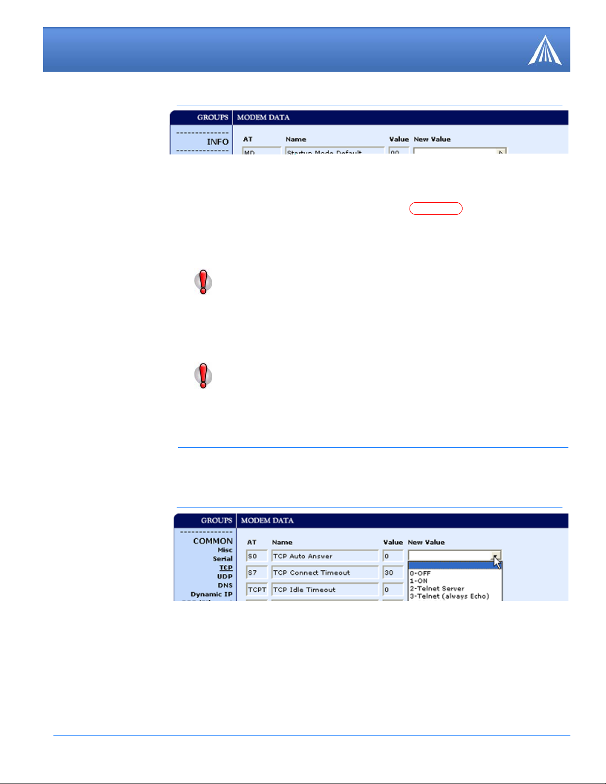
TCP Auto Answer
TCP auto answer (S0=1|2) also allows a TCP connection request to be "answered" when the
modem is idle, not in a data session. The TCP connection request's destination port has to match
the modem's device port.
Note: UDP auto answer may also be set simultaneously with TCP auto answer.
Then, when in the idle state, the modem will accept either a TCP connection
request or UDP incoming packet, and enter a TCP or UDP session as appropriate.
Hybrid Modes
Some previous hybrid modes (MD=5, 6) are no longer implemented as special, unique modes.
Now that UDP auto answer (UDP Half-open, S82=2) can be enabled in conjunction with UDP
PAD mode (MD3), effectively this is the same as MD5 and MD6 previously accomplished. Set
ting MD5 and MD6 are still supported, but not recommended.
PinPoint EDGE/GPRS - User Guide, version 2.32 27
-
Page 34

Data Communication and Host Modes
255.255.255.0
192.168.0.2
192.168.0.1
1 - Use Private IP
AT
Command
Hybrid Mode
(MD5)
Hybrid Mode2
(MD6)
MD 3 3
S82 2 2
S0 1 1
*UDPLAST 0 1
Public and Private Mode
By default, the PinPoint is in Public Mode and will pass the IP address assigned by the Y our Wireless Service Provider network to the device connected to its port. If you need more control over
which gateway address, device address, and netmask that is given out by the DHCP server, you
can use the private host mode, *HOSTPRIVMODE, and set the internal network IP addresses.
The PinPoint will use NAT to forward packets to the end device.
Note: When using Public mode, connect the modem directly to the computer or
other end device. Using a hub or switch may prevent the modem from updating
the IP address of the end device when an IP address is received from the Your
Wireless Service Provider network.
In Wireless Ace, the Private mode settings are part of the PPP/Ethernet group.
FIGURE 7. Wireless Ace: Private Host Mode
• *HOSTPRIVMODE - Set to 1 to enable the explicit IP addresses.
• *HOSTPRIVIP - Set to the IP address you want the PinPoint to give to your device.
• *HOSTPEERIP - Set to the IP address you want for the PinPoint.
• *HOSTNETMASK - Set to the subnetmask (generally, 255.255.255.0).
Note: If you are using Private Mode (*HOSTPRIVMODE=1), you will need to
make sure that *HOSTPRIVIP and *HOSTPEERIP are on the same subnet. If the
subnet mask is 255.255.255.0, it is safe to use 192.168.x.y for each as long as the x
is the same number (0 in the example screen shot above) and the y is different (1
and 2 in the example) and between 0 and 254. The screenshot shows an example.
PinPoint EDGE/GPRS - User Guide, version 2.32 28
Page 35

Data Communication and Host Modes
Keepalive
Keepalive is used to test the PinPoint’s connection by pinging an IP address after a specified period
of inactivity . Keepalive is only recommended for users who have a remote terminated modem that
infrequently communicates to the network or if you have experienced issues over time where the
modem can no longer be reached remotely.
When Keepalive pings the IP address, an acknowledgement indicates there is an active connection
to the network. If the PinPoint does not receive a response from the IP address, it will make addi
tional attempts according to a backoff algorithm before determining the Internet connection is not
functioning properly. If it determines the connection is not fucntioning, the modem will then
attempt to reconnect to Your Wireless Service Provider to reestablish IP connectivity.
Configuring Keepalive
You can use Wireless Ace or a terminal connection to configure Keepalive (page 59). In Wireless
Ace, select Other from the groups menu on the left.
FIGURE 8. Wireless Ace: Keepalive Configuration
-
*IPPING sets the interval, in minutes, you want Keepalive to test the network connection. To
disable Keepalive, set *IPPING to 0 (default setting).
Note: 15 minutes is the minimum time which can be set for Keepalive.
*IPPINGADDR sets the IP address you want to use for the connection test.
Data usage using Keepalive
Keepalive is an optional feature. If you frequently pass data with your modem, you most likely do
not need to have Keepalive enabled. When using Keepalive, be aware that a ping moves approxi
mately 66 bytes of data over the network and is billable by the carrier. The following *IPPING
settings will incur approximate monthly data usage in addition to any other data usage:
15 minutes 400k / month
30 minutes 200k / month
60 minutes 100k / month
120 minutes 50k / month
Caution: If *IPPINGADDR is left blank or is set to an invalid IP address (exam-
ple, an IP which is unreachable or one which is not a valid IP address), modem
performance will be adversely affected.
-
PinPoint EDGE/GPRS - User Guide, version 2.32 29
Page 36

CHAPTER 6 External Inputs & Power Control
The PinPoint has special features for use in a mobile environment. The PinPoint can be configured
to monitor the inputs on its serial port and respond to specific types of events. The PinPoint can
also be configured to change its power mode in order to conserve power.
Capturing Events via External Inputs
The RS232 DB9 interface (the serial port) can be connected to digital switches and configured to
capture contact closures using RTS and DTR to signal external or physical events (such as a tow
bar being activated, opening a door or trunk, the car is turned on or off, etc.).
Setting the DTR and RTS
You can use either Wireless Ace, direct serial communication, or Telnet to configure the modem
using AT commands (
mand options until you see RTSI and DTRI.
FIGURE 1. Wireless Ace: DTR and RTS
T o turn on the DTR (pin 4) digital sensing in the modem, *DTRI should be set to 1. To turn on the
RTS (pin 7) digital sensing, *RTSI should be set to 1.
Note: To use only DTR or only RTS, you only need to configure the one you will
be using.
page 59). Select PinPoint from the menu on the left. Scroll down the com-
Connecting to the Serial Port
You can connect a standard RS232 serial cable to the PinPoint serial port. If you want to use the
DTR switch, wire in a Normally Open switch between the DTR (pin 4) and signal ground (pin 5),
the
PinPoint’s external case, or the power ground (refer to the figures below). If you want to use
the RTS switch, use RTS (pin 7) to the ground (can use th e same grou nd as DTR).
PinPoint EDGE/GPRS - User Guide, version 2.32 30
Page 37

External Inputs & Power Control
5
4
3
2
1
9
8
7
6
< - > GND (Ground)
< - DTR Data Terminal Ready)
< - Rx (Receive)
- > Tx (Transmit)
- > DCD (Data Carrier Detect)
Unused
CTS (Clear to Send)
< -
RTS (Request to Send) - >
DSR (Data to Send) < -
Caution: Never apply voltage to the DTR or RTS inputs. DTR and RTS can
only be switched open or closed to ground.
You may be able to purchase a customizable serial cable to use with DTR and RTS
inputs. Contact your AirLink representative for more information.
When the switch is closed and with *PPINPUTEVT configured, a RAP report will be sent to the
destination IP address indicating that a contact closure has taken place (an external physical event
has occurred). See “RAP Configuration” on
FIGURE 2. PinPoint back
page 40.
FIGURE 3. Serial Port Diagram : Female DB-9 DCE (not to scale)
PinPoint EDGE/GPRS - User Guide, version 2.32 31
Page 38

External Inputs & Power Control
FIGURE 4. DTR and RTS switches using Pin 5 (signal GND) as the common ground
Power Modes
The PinPoint can be configured to switch power modes in response to specific events in order to
conserve a vehicle's battery life. The stand-by state (low-power mode) will prevent the modem
from draining the battery while allowing the modem to quickly power up to regular operation
when it is needed.
FIGURE 5. Wireless Ace: Low Power
The PinPoint can power down and enter the stand-by state when the voltage to the modem drops
below a configured threshold (such as when the vehicle is turned off), or when DTR changes
(commonly a contact or voltage controlled by the key switch, signaling when the vehicle is turned
off).
Note: If one or both DTR or RTS have been configured to be used as digital inputs,
then low power mode cannot be configured to respond to DTR.
If you want to use Low Power Mode, you should choose either voltage level or
DTR/RTS as the trigger, not both.
PinPoint EDGE/GPRS - User Guide, version 2.32 32
Page 39

External Inputs & Power Control
Power Effect on Modem State
Once the transition from powered on to standby, low-power mode starts, the modem will change
state to AT mode. This results in the current mode being gracefully terminated. For the brief period
when the modem is preparing for low-power mode, the modem will remain in AT mode (i.e. won't
auto-answer, ATD will fail, etc.). Once low-power mode is entered, the modem will then discard
any data received on the host port.
When the modem is woken from low-power mode, the same behavior occurs as upon power on.
The modem starts in AT mode, and then after 5 seconds will enter the default mode (See “Host
Modes” on page
20).
PinPoint EDGE/GPRS - User Guide, version 2.32 33
Page 40

CHAPTER 7 Global Positioning System (GPS)
The PinPoint is equipped with a GPS receiver to ascertain its position to track the movements of a
vehicle or other devices which move. The PinPoint relays the information of its location as well as
other data for use with tracking applications.
Tracking Applications used with AirLink modems:
• Air-Trak
• Track Your Truck
• Track Star
• DeLorme Street Atlas USA
• Microsoft Streets and Trips
• CompassCom
• Zoll Data
• and many more...
GPS Overview
The Global Positioning System (GPS) is a satellite navigation system used for determining a location and providing a highly accurate time reference almost anywhere on Earth. The US military
refers to GPS as Navigation Signal Timing and Ranging Global Positioning System (NAVSTAR
GPS).
GPS consists of a “constellation” of at least 24 satellites in 6 orbital planes. Each satellite circles
the Earth twice every day at an altitude of 20,200 kilometres (12,600 miles). Each satellite is
equipped with an atomic clock and constantly broadcasts the time, according to its own clock,
along with administrative information including the orbital elements of its motion, as determined
by ground-based observatories.
A GPS receiver, such as the PinPoint, requires signals from four or more satellites in order to deter mine its own latitude, longitude, and elevation. Using time synced to the satellite system, the
receiver computes the distance to each satellite from the difference between local time and the time
the satellite signals were sent (this distance is called psuedoorange). The locations of the satellites
are decoded from their radio signals and a database internal to the receiver. This process yields the
location of the receiver. Getting positioning information from fewer than four satellites, using
imprecise time, using satellites too closely positioned together, or using satellites too close to the
Earth’s curve will yield inaccurate data.
PinPoint EDGE/GPRS - User Guide, version 2.32 34
Page 41

Global Positioning System (GPS)
The GPS data is then transmitted to a central location which uses a tracking application to compile
information about location, movement rates, and other pertinent data.
Note: Depending on the location of the satellites in relation to the modem’s loca-
tion and how many signals are being received, the PinPoint may encounter “GPS
drift”. The PinPoint may report it is in a location a few feet from its actual location
because it does not employ differential GPS.
AirLink Remote Access Protocol (RAP)
The AirLink Remote Access Protocol (RAP) is a proprietary binary message format. The PinPoint
uses the UDP (User Datagram Protocol) to communicate with the host server. RAP was originally
designed to work specifically with AirLink Tracking System (ATS), but other 3rd party applica
tions have been developed to take advantage of the RAP messaging format.
Examples of tracking applications using RAP:
• Air-Trak
• TrackStar
• CompassCom
• Zoll Data
• HTE
• Spillman
• and others...
-
National Marine Electronics Association (NMEA)
National Marine Electronics Association (NMEA) is a protocol by which marine instruments and
most GPS receivers can communicate with each other. NMEA defines the format of many different
GPS message (sentence) types, which are intended for use by navigational equipment.
Example of a tracking application using NMEA:
• Microsoft Streets and Trips
Trimble ASCII Interface Protocol (TAIP)
Trimble ASCII Interface Protocol (TAIP) is a digital communication interface based on printable
ASCII characters over a serial data link. TAIP was designed specifically for vehicle tracking appli
cations but has become common in a number of other applications, such as data terminals and portable computers, because of its ease of use.
Example of a tracking application using TAIP:
• DeLorme Street Atlas USA
-
PinPoint EDGE/GPRS - User Guide, version 2.32 35
Page 42

Global Positioning System (GPS)
Datum
In addition to different reporting protocols, the PinPoint supports the most widely used GPS datum.
The GPS datum is the method of ascertaining the position of the GPS device using a specific reference point location. The datum used can influence the accuracy of the GPS positioning.
Datum Supported by the PinPoint:
• WGS84 • NAD83 • NAD27
Real-Time Clock Sync
Every hour, the PinPoint will sync the internal Real Time Clock (RTC) with the Universal Time
Coordinated (UTC) received from the GPS satellites.
Many tracking applications will translate the time reported by the PinPoint as part of the GPS message to the appropriate local time zone using the UTC offset (i.e. California is UTC-8 and New
York is UTC-5).
Note: Wireless Ace displays the current time (UTC) set in the modem and does not
translate it to the local time zone. If the modem is in California and it is 8 a.m., the
modem’s time will be shown as 4 p.m, since UTC is 8 hours “ahead” of Pacific
time (UTC+8).
TCP GPS Polling
The PinPoint can easily and quickly be polled for location by opening a TCP connection to port
9494 (default). Once the connection is established, the PinPoint will send a report with the current
position using the GPS report type the modem is configured to use.
You can change the port for the TCP GPS poll using *TCP.
FIGURE 1. Wireless Ace: *PPTCPPOLL
Note: As a security measure, the TCP connection to the *PPTCPPOLL port must
be from the IP address specified for the ATS Server IP in *PPIP.
PinPoint EDGE/GPRS - User Guide, version 2.32 36
Page 43

Global Positioning System (GPS)
Configuring the PinPoint for GPS
T o configure your modem’ s GPS settings, you can use either Wireless Ace or a terminal connection
to configure the modem using A T commands (
all use Wireless Ace. Most of the settings are in the group: PinPoint.
Before you Begin to Configure GPS
To decide what configuration you need for your PinPoint, there are some fundamental considerations:
1. Protocol: What is the GPS protocol used by your tracking application and what type of reports
will you need?
2. Datum: What is the datum supported by your tracking application?
3. DNS: Will you need DNS support?
The main sections below detail how to set up the configuration for RAP (page 40), RAP special
features (page 42), RAP Store and Forward (page 44), NMEA (page 46), and TAIP (page 47).
Most of the PinPoint commands are covered in the main sections below.
page 59). The configuration examples in this chapter
You can use a fully qualified domain name instead of an IP address for most configuration options calling for an IP address if your PinPoint is configured to use
DNS. DNS settings frequently come directly from Y our W ireless Service Provider
while your PinPoint is registering on the cellular network and receiving it’s IP
address.
Configuring the Datum
You can change the Datum used by your PinPoint by configuring *PPGPSDATUM. Match the
Datum to the Datum used by your tracking appliction.
Note: Some PinPoint models do not support configuring the Datum with Wireless
Ace. If the option does not appear in Wireless Ace when you connect to the Pin
-
Point, then your modem does not support it.
Over-The-Air (Remote) Host
To set the PinPoint to report to an extern al or remote host, configure *PPIP (ATS Server IP ) and
*PPPORT (Server Port). *PPIP will work with any remote host.
FIGURE 2. Wireless Ace: *PPIP and *PPPORT
PinPoint EDGE/GPRS - User Guide, version 2.32 37
Page 44

Global Positioning System (GPS)
Local Host
To set the PinPoint to report to a local host, one directly connected to the PinPoint’s serial port,
configure the port to be used with S53 - Destination Port. The local IP address will automatically
be used for local reports. S53, in Wireless Ace, is part of the Misc menu option.
FIGURE 3. Wireless Ace: S53
If you need to send reports to additional local ports, you can specify other ports with *PPLATSEXTRA. Local Reports can be sent to up to 7 additional ports consecutively following the S53
port. If S53=1000 and *PPLATSEXTRA=4, reports will be sent to 1000, 1001, 1002, 1003, and
1004. In PPLATSEXTRA, specify the number of ports where you want the reports sent, 0 to 7 (0
disables extra ports).
FIGURE 4. Wireless Ace: *PPLATSEXTRA
Report Types
There are several report types available. For remote reports, set *PPGPSR. For local reports, set
*PPLATSR. These settings are not next to each other, but are on the same page.
FIGURE 5. Wireless Ace: *PPGPSR and *PPLATSR
0 - *MF, Legacy reports for use with ATS version 4 and older. 11 - Global Positioning System
(GPS) data.
12 - GPS data with the UTC time and date.
13 - GPS with time and date and Radio Frequency data from the antenna. D0 - Xora reports.
E0 - NMEA GGA and VTG sentences.
E1 - NMEA GGA, RMC, and VTG sentences.
F0 - TAIP data
F1 - TAIP compact data
Note: The PinPoint can be configured to supply one type of report to a remote host
and a different report type locally through the serial port at same time. However,
there may be conflicts due to the local and remote reporting being in different
modes and not all features to both modes may be available.
PinPoint EDGE/GPRS - User Guide, version 2.32 38
Page 45

Global Positioning System (GPS)
Sending Reports Automatically
You can configure the PinPoint to send reports based on a time interval and on the movement of a
vehicle (based on it’s position from one time to the next).
FIGURE 6. Wireless Ace: Automatic Reports
*PPTIME - Location report sent every set time interval (seconds).
*PPDIST - Location report sent only if the position is more than the set distance (x 100
meters).
*PPTSV - Location report sent if the vehicle has been in one location (stationary) for more than
a set time interval (minutes).
*PPMINTIME - Location report sent be sent at no less than this time interval (seconds).
Note: If you’re implementing both a time interval and distance interval for reports,
the PinPoint will use the timer which expires first.
The reporting interval can impact your data usage. If the interval is set frequently,
you may want to have a high usage or unlimited data plan.
One mile is approximately 1600 meters. 1000 meters is one kilometer.
If you are sending reports on the local serial port, and/or if you want them sent automatically, you
will need to set *PPLATS. The time interval, just as for *PPTIME, is in seconds.
FIGURE 7. Wireless Ace: Local Automatic Reports
The PinPoint can be configured to wait a specific amount of time after initialization before any
reports are sent.
FIGURE 8. Wireless Ace: GPS Initialization Timer
PinPoint EDGE/GPRS - User Guide, version 2.32 39
Page 46

Global Positioning System (GPS)
RAP Configuration
RAP has additional features which allow reports based on external physical events, input from a
3rd party devices, store and forward processing, etc.
Most of the configuration settings for RAP can be changed with the RAP configuration command
message. Refer to the AirLink Tracking System User Guide.
RAP Reports Over-The-Air (Remote)
To configure the PinPoint to send RAP repo rts to a remote server, you will need to set 3 commands: *PPIP, *PPPORT, and *PPGPSR.
FIGURE 9. Wireless Ace: RAP Reports Remote
1. Set the IP (*PPIP) and port (*PPPORT) to the IP and port of the server to which you want the
reports sent.
2. Set the GPS Report Type (*PPGPSR) to your preferred RAP report type.
11 - GPS - Global Positioning System data
12 - GPS + Date - GPS data with the UTC time and date
13 - GPS + Date + RF - GPS data with the UTC time and date and Radio Frequency informa-
tion from the antenna.
If you need to use a dynamic IP address for the host server, you can use the RAP configuration
command to change the value for *PPIP (see below).
Note: If your PinPoint is on a mixed network (some of the fleet on another cellular
network), you will need to specify the IP of the server in *PPIP and configure the
PinPoint not to change the server IP with a RAP configuration command using
*PPIGNOREIP. This will prevent the ATS server configuration packets from
changing the *PPIP value.
FIGURE 10. Wireless Ace: *PPIGNOREIP
RAP Reports over a Local Connection (PPP or SLIP)
Local reports are sent to the local IP address of the computer or device connected to the serial port
of the PinPoint using PPP or SLIP. To configure the modem to send to the local IP, you will need
to set 3 commands: S53, *PPLATS, and *PPLATSR.
PinPoint EDGE/GPRS - User Guide, version 2.32 40
Page 47

Global Positioning System (GPS)
1000
12-GPS+Date
FIGURE 11. Wireless Ace: RAP Local Reports
1. Set the port (S53) to the local port to which you want the reports sent. The local IP will auto-
matically be used. S53, in Wireless Ace, is part of the Misc menu option.
2. Set the ATS Local Report Type (*PPLATSR) to your preferred RAP report type.
11 - GPS - Global Positioning System data
12 - GPS + Date - GPS data with the UTC time and date
13 - GPS + Date + RF - GPS data with the UTC time and date and Radio Frequency informa-
tion from the antenna.
3. Set Local ATS Reporting Time Interval (*PPLATS) to the number of seconds you want as an
interval between reports being sent. If *PPLATS is set to 0, reports will only be sent if a poll
command is issued by the local client.
RAP Message format
In a RAP-based system, each PinPoint sends command status and responses to the Server which is
master and sends commands to one or more PinPoint devices
For reliability, the server expects each command to be acknowledged within a time-out period . If
the acknowledgement packet (ACK) is not received within the time-out period, the server will
retransmit the command.
The RAP messages are in Hex and are referred to by their message ID.
GPS Reports
0x11 Simple GPS Report - Report contains GPS latitude and longitude in 1/100,000 degrees,
GPS velocity in kilometers/hour, GPS Direction in 2 degree increments, UTC time (but not
date), GPS satellite count and quality, and optional data.
0x12 Simple GPS Report with the addition of the UTC date.
0x13 Simple GPS Report with the addition of the UTC date and including radio frequency data
with the GPS point.
0x20-0x23 indicate the state changes of either the RTS or DTR (See “Store and Forward for
RAP” on page 44.) in addition to the same data as in an 0x12 report.
0x24-0x2B indicate the state changes of the COM1000 inputs (See “COM1000 Event Reports”
on page 43.) in addition to the same data in an 0x12 or 0x13 report.
Note: It is recommended to use Report type 0x12 or 0x13 when Store and Forward
(
page 44) is enabled.
PinPoint EDGE/GPRS - User Guide, version 2.32 41
Page 48

Global Positioning System (GPS)
Power Reports
0x10 Power Up Report - Sent by the modem when it is powered up (either as a result of being
power cycled or with a software reset).
0x30 Power Sleep Report - Sent by the modem when it is about to power down into a lowpower state (not supported in some early PinPoint models).
0x31 Power Wakeup Report - Sent by the modem when it is returned to a full power state from
a low-power state (not supported in some early PinPoint models)
Additional RAP Features
RAP allows additional information to be sent with the reports to enable a richer tracking feature
set. Configure RAP as you would normally for remote or local reports (
on page 40.).
Device ID
By enabling *PPDEVID, the device ID is sent as part of the RAP message to make identification
easier in a network or fleet of vehicles equipped with PinPoint modems.
See “RAP Configuration”
FIGURE 12. Wireless Ace: *PPDEVID
Caution: If the PinPoint is using a dynamic IP, *PPDEVID needs to be enabled.
With the device ID enabled, the PinPoint will use the value configured for NETPHONE unless
NETPHONE is empty in which case the ESN of the modem will be used.
Odometer Data in Reports
When the odometer is enabled, the PinPoint will calculate distance based on GPS data. The
modem’s odometer calculations can be included in the RAP message.
FIGURE 13. Wireless Ace: Odometer Reports
PinPoint EDGE/GPRS - User Guide, version 2.32 42
Page 49

Global Positioning System (GPS)
Note: The PinPoint’s odometer calculations may not match the odometer in the
vehicle itself. The PinPoint odometer is not connected to the vehicle’s, it is
entirely based on calculations of GPS readings.
Serial Input Event Reports
You can configure the PinPoint to send reports based on the state of the DTR and/or RTS pins on
the serial port. Refer to “Capturing Events via External Inputs” on page
devices.
Once the serial port has been connected, you will also need to enable the event reporting for GPS.
FIGURE 14. Wireless Ace: Enabling RTS and DTR for Input Events
If you have connected the physical device to the RTS pin and ground, you will need to enable
RTSI. If you have connected it to the DTR pin and grou nd, you wi ll need to enable DTRI. You
can have different devices connected to each. If you have two connected, enable both.
30 to set up the external
To enable the reports themselves, use *PPINPUTEVT.
FIGURE 15. Wireless Ace: Input Event Reports
The report type will indicate the state of change in either R TS or DTR. The contents of the report
will be the same as Report Type 0x12 (GPS data with date) wit h the addi tion of the event report.
Input Value Report Type
DTR 0 0x20
DTR 1 0x21
RTS 0 0x22
RTS 1 0x23
COM1000 Event Reports
Support for the COM1000 is enable with the command *PPCOM1000=1. Once enabled, ALEOS
will receive the reports from a properly configured COM1000 and add the state of the extra inputs
to RAP packets sent to ATS.
FIGURE 16. Wireless Ace: COM1000 Events - *PPCOM1000
PinPoint EDGE/GPRS - User Guide, version 2.32 43
Page 50

Global Positioning System (GPS)
The report type will indicate the state of change in the inputs. The contents of the report wi ll be
the same as Report Type 0x12 (GPS data with date) or 0x13 (GPS data with date and RF data)
with the addition of the event report.
Store and Forward for RAP
Store and Forward RAP can provide seamless coverage even in areas with intermittent cellular
coverage. If the PinPoint leaves coverage or has very low signal (an RSSI of -105 or lower), it will
store the GPS messages in memory. When the modem re-enters cellular coverage, it will then for
ward the messages as configured. The PinPoint can also store messages and send them to the
server in a packet rather than individually to conserve bandwidth.
FIGURE 17. Wireless Ace: Store and Forward
-
Once you have enabled SnF, *PPSNF, you can determine how you want the messages sent using
*PPSNFB, Store and Forward Mode:
Normal - Each report is sent immediately.
Polled - Reports held until requested by the server.
Grouped - Reports held until the total is equal or greater than *PPSNFM which sets the packet
size of grouped reports.
Store and Forward Reliable Mode
The Store and Forward Reliable Mode allows the PinPoint to ensure all messages are received by
the server even if the connection between them goes down for a period of time (such when a vehi
cle passes through a location where the cellular signal is weak or non-existent).
FIGURE 18. Wireless Ace: Store and Forward Reliable Mode
With Reliable Mode enabled, *PPSNFR, the PinPoint will transmit a sequence number (1 to 127)
as part of a packet of messages (may contain one or more reports). To reduce overhead, the server
only acknowledges receipt of every eighth packet. The PinPoint considers that 8 a “window” of
outstanding packets.
-
If the PinPoint doesn’t receive acknowledgement for a “window”, the modem will PING the server
with a message containing the sequence numbers of the first and last packets that haven’t been
PinPoint EDGE/GPRS - User Guide, version 2.32 44
Page 51

Global Positioning System (GPS)
acknowledged. The PinPoint will continue until the server acknowledges receipt. When the PinPoint receives the acknowledgement, it will advance its “window” to the next group.
When the PinPoint is first powered on (or reset), it will send a Set Window message to sync up
with the server for the current “window”.
On the other side, if the server receives an out of sequence packet, it will send a message to the
modem noting the missing sequence and the PinPoint will retransmit.
GPS Time, Latitude, and Longitude can be added, *UDPRGPS, to the packet sequence data for
Reliable Mode.
FIGURE 19. Wireless Ace: Adding GPS Time, Latitude, and Longitude to Reliable UDP
data
Note: Using SnF Reliable Mode can cause excessive data traffic if the sequence
number is not returned.
Sending Reports
You can configure the PinPoint to send reports based on a time interval and on the movement of a
vehicle (based on it’s position from one time to the next).
FIGURE 20. Wireless Ace: Automatic Reports
*PPTIME - Location report sent every set time interval (seconds).
*PPDIST - Location report sent only if the position is more than the set distance (x 100 meters)
*PPTSV - Location report sent if the vehicle has been in one location (stationary) for more than
a set time interval (minutes).
*PPMINTIME - Location report sent at no less than this time interval (seconds).
Flush on Event
If you have events enabled, with *PPFLUSHONEVT, you can configure the PinPoint to flush the
SnF buffer when an event occurs. This will immediately send all pending SnF messages to the
host. This allows an event, such as a vehicle being powered on or a tow bar activated, to be imme
diately sent, so its cause can be acted on without delay.
PinPoint EDGE/GPRS - User Guide, version 2.32 45
-
Page 52

Global Positioning System (GPS)
FIGURE 21. Wireless Ace: Store and Forward Flush on Event
Note: Outstanding packets can include messages already sent to the server that
haven’t been acknowledged (SnF Reliable Mode) whether they have been received
by the server or not.
NMEA Configuration
The PinPoint transmits standard NMEA GPS messages as well as the proprietary RAP format.
Streaming NMEA Messages over the local port
The PinPoint can be configured to send standard NMEA messages (sentences) in ASCII over the
serial port without a PPP connection to the local computer. For examples of the message format
descriptions, refer to
page 136.
Send the command ATGPS1 to the serial portto begin the NMEA stream. The example below
shows the stream in HyperTerminal connecting directly to a PinPoint via the compo rt.
FIGURE 22. HyperTerminal: NMEA Stream
To stop the stream, with either terminal connection, use the command ATGPS0 (this can be
entered even while data is streaming). You can also use AT*PGPS=1 then AT&W to allow you
to stream the data even after the modem is reset.
You can also issue this command using Wireless Ace to stream the data from the serial port without using HyperTerminal or another terminal application. The data will stream even after the
modem is reset.
FIGURE 23. Wireless Ace: NMEA Strings
PinPoint EDGE/GPRS - User Guide, version 2.32 46
Page 53

Global Positioning System (GPS)
1000
E0-NMEA GGA+VTG
1000
5
E1-NMEA GGA+VGA+RMC
NMEA Messages Over-The-Air (Remote)
To configure the PinPoint to send NMEA reports to a remote server, you will need to set 3 commands: *PPIP, *PPPORT, and *PPGPSR.
FIGURE 24. Wireless Ace: NMEA Remote Reports
1. Set the IP (*PPIP) and port (*PPPORT) to the IP and port of the server to which you want the
reports sent.
2. Set the GPS Report Type (*PPGPSR) to your preferred NMEA sentence format.
E0 - Output the GGA and VTG sentences.
E1 - Output the GGA, RMC, and VTG sentences.
NMEA Messages over a Local Connection (PPP)
Local reports are sent to the local IP address of the computer or device connected to the serial port
of the
PinPoint using PPP. To configure the modem to send to the local IP, you will need to set 3
commands: *S53, *PPLATS, and *PPLATSR.
FIGURE 25. Wireless Ace: NMEA Local Reports
1. Set the port (S53) to the local port to which you want the reports sent. The local IP will auto-
matically be used. S53, in Wireless Ace, is part of the Misc menu option.
2. Set the ATS Local Report Type (*PPLATSR) to your preferred NMEA sentence format.
E0 - Output the GGA and VTG sentences.
E1 - Output the GGA, RMC, and VTG sentences.
3. Set Local ATS Reporting Time Interval (*PPLATS) to the number of seconds you want as an
interval between reports being sent.
TAIP Emulation Configuration
The TAIP emulation functionality allows the Pi nPoint to operate in a limited manner with clients
which only understand the Trimble ASCII Interface Protocol (TAIP).This emulation is enabled by
PinPoint EDGE/GPRS - User Guide, version 2.32 47
Page 54

Global Positioning System (GPS)
F0-TAIP data
21000
F0-TAIP data
0
setting the GPS report format, directing the modem to listen for T AIP messages, and disabling AirLink Binary/ATS formatted messages. For the message format descriptions, refer to page 138.
TAIP Messages Over-the-Air (Remote)
To configure the PinPoint to send TAIP reports to a remote server, you will need to set 3 commands: *PPIP, *PPPORT, and *PPGPSR.
FIGURE 26. Wireless Ace: TAIP Remote Reports
1. Set the IP (*PPIP) and port (*PPPORT) to the IP and port of the TAIP server.
2. Set GPS Report Type (*PPGPSR) to F0-TAIP data.
Note: Unlike standard TAIP which simply sends to the last client to request auto-
matic reports, the remote reports are sent to the destination address (*PPIP) and
destination port (*PPPORT).
TAIP Messages over a Local Connection (PPP)
Some T AIP client applications can send TAIP requests and listen for reports using a local connection. Generally this is done over the serial port using PPP. To configure this option, you will need
to set four commands: *PPIP, S53, *PPGPSR, and *PPLATS.
FIGURE 27. Wireless Ace: TAIP Local Reports
1. Set the IP (*PPIP) to the local IP of the PinPoint (if you are receiving reports using PPP, you do
not need to set *PPIP).
2. Set the port (S53) to 21000. The local IP will automatically be used. S53, in Wireless Ace, is
part of the Misc menu option.
3. Set GPS Report Type (*PPGSPR) to F0 - TAIP Data.
4. Set the Local ATS Reporting Time Interval (*PPLATS) to 0 to disable unsolicited local reports.
With this configuration, the PinPoint will listen for TAIP requests on the local IP (192,168.13.31
by default) and port 21000. Once a TAIP request command has been received, the PinPoint will
PinPoint EDGE/GPRS - User Guide, version 2.32 48
Page 55

Global Positioning System (GPS)
1000
F0-TAIP data
F0-TAIP data
begin issuing TAIP reports (e.g. DPVs) to the local IP and port 21000. The client application
should be listening for reports on this IP address and port.
No unsolicited reports will be sent from the PinPoint to the local client application.
Sending Unsolicited TAIP Messages over a Local Connection (PPP)
Standard TAIP requires a request before GPS reports are sent. The PinPoint, however, can be configured to allow TAIP formatted messages to be sent over any UDP Port with out request commands. This is useful for those applications which can listen for TAIP messages but cannot send
UDP request packets.
This configuration sends TAIP GPS reports to whatever address and UDP Port you select. You
will need to set 3 commands: S53, *PPLATS, and *PPLATSR.
FIGURE 28. Wireless Ace: TAIP Local Reports, Unsolicited
1. Set the port (S53) to 1000. The local IP will automatically be used. S53, in Wireless Ace, is
part of the Misc menu option.
2. Set ATS Local Report Type (*PPLATSR) to F0 - TAIP Data.
3. Set the Local ATS Reporting Time Interval (*PPLATS) to 5 to send reports every 5 seconds
(can be adjusted as circumstances warrant).
Using TAIP Command Emulation
To configure the PinPoint to use TAIP emulation set GPS Report Type (*PPGSPR) to F0 - TAIP
Data.
FIGURE 29. Wireless Ace: TAIP Emulation
Note: With TAIP emulation, the PinPoint will listen for TAIP messages on port
21000. RAP will be disabled and no RAP messages or commands will be sent or
received on that port.
PinPoint EDGE/GPRS - User Guide, version 2.32 49
Page 56

Global Positioning System (GPS)
TAIP ID
The TAIP messages can be configured to send the user specified identification number (ID). This
greatly enhances the functional capability of the unit in a network environment. Set the ID using
*PPTAIPID.
FIGURE 30. Wireless Ace: TAIP ID
Supported TAIP Commands
The TAIP emulation will accept the following TAIP message types:
SRM (Set Reporting Mode) allows the client to set the reporting mode configuration. The
report mode configuration is not stored in non-volatile memory and such should be resent upon
a unit reset. This behavior emulates that specified in TAIP specifications.
QRM (Query Reporting Mode) reports the reporting mode configuration (returns an “RRM”
message).
SID (Set ID) allows the client to set the TAIP ID (AT*PPTAIPID can also be used to set the
TAIP ID). The TAIP ID, when set with a “SID” message, will be written to non-volatile mem
ory.
QID (Query ID) reports the TAIP ID (returns an “RID” message).
DPV configures automatic reporting of PV (Position/Velocity) reports based on distance trav -
eled and a maximum time. The delta distance value specified in the message is converted to
hundreds of meters and stored as *PPDIST. The maximum time interval is stored as *PPTIME.
Currently the minimum time and epoch values are ignored.
FPV configures periodic reporting of PV (Position/V elocity) reports. The time interval from the
message is stored at *PPTIME. Currently the epoch value is igno red.
QPV (Query Position Velocity) responds with a PV (Position/Velocity) report.
-
The TAIP emulation will generate the following reports corresponding to the appropriate event
(either a query for it, echoed due to a set, or due to an automatic reporting event).
RRM (Report Reporting Mode) reports the reporting mode configuration.
RID (Report ID) reports the TAIP ID.
RPV (Report Position/Velocity) reports Position/Velocity.
PinPoint EDGE/GPRS - User Guide, version 2.32 50
Page 57

CHAPTER 8 Hardware Installation
Cellular
GPS
Your AirLink PinPoint should be mounted in a position that allows easy access for the cables so
they are not bent or constricted. The LEDs on the front panel should be visible for ease of opera
tional verification. Y ou should ensure that there is adequate airflow around the modem but that it is
kept free from direct exposure to the elements (sun, rain, etc.)
Possible locations for your PinPoint installed in a vehicle are in a trunk away from where luggage
or other items won’t be likely to dislodge it, under or in the console, or behind seats. Ensure the
location is secure both against abrupt movements of the vehicle and from other items coming into
contact with the modem.
An optional accessory for your PinPoint is a mounting kit. The bracket is designed to snugly cradle the modem and hold it in place where you need it.
Modem placement with diagrams of the mounting bracket can be found in the
Appendix, “Modem Placement” on page
-
54.
FIGURE 1. PinPoint connecters
Connecting the Antennas
Antennas selected should not exceed a maximum gain of 5 dBi under standard installation configuration. In more complex installations (such as those requiring long lengths of cable and/or multiple connections), it’s imperative that the installer follow maximum dBi gain guidelines in
accordance with the FFC’s, Industry Canada’s, or your country’s radio communications regula
tory body’s regulations.
-
PinPoint EDGE/GPRS - User Guide, version 2.32 51
Page 58

Hardware Installation
Your AirLink PinPoint will work with most Dual-Band PCS cellular antennas with a TNC connector that works in the high and low frequencies of EDGE/GPRS . Connect the antenna or RF
cable directly to the antenna connector on the back of the PinPoint.
Your PinPoint will work with most standard active GPS antennas. Connect the GPS antenna or
cable directly to the threaded SMA connector.
Connecting Power
Your PinPoint can be used with either DC (available in most automobiles) or 110 AC (standard US
wall power) with the appropriate power adapter (available from AirLink).
The power cable positive lead should be connected to the battery or power source positive terminal. The power cable negative lead should be connected to the battery or power source negative terminal.
Note: When using a DC power source (such as a car battery or solar cell), AirLink
recommends placing a fuse (1-2 Amp) on the line close to the power source to pro
tect your power source from possible surges due to shorts or other line issues.
-
Connecting the PinPoint to a computer or other device
Your PinPoint’s serial port can be connected directly to most computers or other devices using a
standard straight through cable. If you have a DCE device, you will need a null modem or null
modem cable.
Your PinPoint can also be connected to a USB to serial device connected to a computer or other
device which does not have an available serial port but does have USB.
PinPoint Indicator Lights
When your PinPoint is connected to power and an antenna, there is a specific pattern to the lights to
indicate its operation mode.
FIGURE 2. PinPoint indicator lights
PinPoint EDGE/GPRS - User Guide, version 2.32 52
Page 59

Hardware Installation
Tx (transmit) and Rx (receive) - Lights will flash as data is transferred to and from the PinPoint
on the remote network.
RSSI(signal level) - Light shows the strength of the signal and may be nearly solid (strong signal)
or flashing (weaker signal). A slow flash indicates a very weak signal.
Reg (registation) - Indicates the PinPoint has acquired an IP from Your W ireless S ervice Provider.
Chan (channel) - Indicates the modem has acquired a network channel.
Link - Indicates a successful connection to the cellular network.
GPS - Indicates a GPS fix. When lit, the PinPoint has GPS coordinates to report.
Pwr (power) - Indicates the power adapter is connected and there is power getting to the modem.
The Reset button performs the same function as unplugging power from the modem and plugging
it back in. Reset will not alter any saved configuration settings.
Light Patterns
The LEDs on the front of the modem will respond in different patterns to indicate modem states.
• Normal - Each LED, mentioned above, lit as applicable.
• Start up - The LEDs will cycle from left to right.
• Low Power - All LEDs will be off except the power LED which will blink every 3 seconds.
• Passthru - The Chan, Reg, and Link LEDs will blink in tandem. The TxRx LED will blink
when transmitting or receiving data.
• SOS - The Chan and Err or Serv LEDs will blink alternate to each other.
PinPoint EDGE/GPRS - User Guide, version 2.32 53
Page 60

APPENDIX A Modem Placement
When decided on a location to install your PinPoint, make sure the modem will be away from
direct exposure to the elements (sun, rain, etc.). Excess cables can be bundled and tied with twistties or other appropriate binders, but the less the cable is wrapped and bound together, the better the
modem will perform.
Optional Mounting Kit
An optional accessory for your modem is a mounting kit. The bracket is designed to snugly cradle the modem and hold it in place where you need it.
The PinPoint “snaps” into place in the bracket locking into the grooves on the PinPoint case. The
bracket can be further secured with a twist-tie set into the grooves on the top for situations where
the PinPoint may be subjected to violent movement, such as in the back of an automobile. In
most stationary installations, such as in a field or pipe, the PinPoint and bracket shouldn’t require
a twist-tie.
The bracket can be attached to the location using #6 screws (mounting hole diameter approximately 0.150").
FIGURE 1. Mounting Bracket
PinPoint EDGE/GPRS - User Guide, version 2.32 54
Page 61

Modem Placement
FIGURE 2. PinPoint Mounting Bracket, part number 10 0-170-1005
PinPoint EDGE/GPRS - User Guide, version 2.32 55
Page 62

Modem Placement
GPS Antenna Location
There are three options for an antenna:
• magnetic roof-mount
• through glass-mount
• permanent mount
Mount the GPS Antenna in the vehicle. The less the cable is wrapped and bound together, the better it will perform. Place it on the roof, or on the dash, or rear panel where it has a good view of
the sky (greater than a 90 angle view of the sky).
FIGURE 3. GPS Antenna Placement for a Vehicle
FIGURE 4. PinPoint Placement in a Vehicle
PinPoint EDGE/GPRS - User Guide, version 2.32 56
Page 63

APPENDIX B Specifications for the PinPoint EDGE/
GPRS
Physical Characteristics:
• Weight: 2 lbs
• Size: 6.8” x 3.3” x 2”
• RF Antenna Connector: 50 Ohm TNC
• GPS Antenna Connector : SMA
• Serial Interface: RS232 DB-9F with 1200-115200 bps (see below for diagram)
• Status LEDs
Data Services & RF Features
• Quad Band GPRS/EDGE (850, 900, 1800 and 1900 MHz)
• EDGE (MS Class 10) w/ GPRS (MS-12) Fallback
• EDGE data rates 236 Kbps maximum, 70-90 typical downlink and 118 maximum, 50-60 typi-
cal uplink
• GPRS data rates 7.6 Kbps maximum, 30-50 Kbps typical downlink /uplink
• Coding Schemes 1-9, Full PBCCH Support
• Network: 1900/850 MHz GPRS
• Transmit frequency: 1850-1910 MHz and 824-849 MHz
• Transmit power range at antenna port: 1.0 W for 1900 MHz and 0.8W for 850 MHz
• Transmitter can reduce output power when near a base station as per GSM specifications
• Receiver frequency: 1930-1990 MHz and 869-894 MHz
• Receiver sensitivity: typical -107 dBm (2.439% bit error rate)
• Multislot Class 8
Environmental:
• Operating ranges: -30°C to +°C
• Humidity: 5%-95% Non-condensing
PinPoint EDGE/GPRS - User Guide, version 2.32 57
Page 64

Specifications for the PinPoint EDGE/GPRS
Power Management:
• Advanced Power Management features
• Low power consumption
• Dormant connection (idle for 10-20 seconds): 60 mA at 12 VDC
• Input Voltage: 9 VDC to 28 VDC
• Input Current: 20 mA to 350 mA
• Typical Transmit/Receive: 300ma at 12VDC
• Low power mode: 20 mA at 12 VDC
Power consumption
Modem Idle Transmitting
PinPoint 80 mAh 300 mAh
Serial Port Pinouts
The cable between the PinPoint and a computer or other serial device needs to be wired straightthrough (pin 1 goes to pin 1, pin 2 to pin 2, etc.). If your end device connected to the PinPoint is a
DCE device, you will need a null-modem cable.
FIGURE 1. : Female DB-9 DCE
PinPoint EDGE/GPRS - User Guide, version 2.32 58
Page 65

APPENDIX C AT Commands
Wireless Ace is a graphical interface for configuring your PinPoint. It is highly recommended that
you use this utility to modify any parameters, however a terminal emulation application, such as
HyperTerminal, see below, can be used instead with typed AT commands.
Note: Some commands can only be configured using a terminal emulation and
typed AT commands. Some commands also require PassThru mode.
You can use a fully qualified domain name instead of an IP address for most configuration options calling for an IP address if your is configured to use DNS. DNS
settings frequently come directly from Your Wireless Service Provider while your
is registering on the cellular network and receiving it’s IP address.
Using Wireless Ace
With Wireless Ace, you only need to find the comm and listed and then enter the new value in the
space provided. For those commands which have specific parameters, the choices will be in a drop
down menu.
FIGURE 1. Wireless Ace: Entering new configuration values
To set or commit the changes in the modem, use the Write button at the top of Wireless Ace interface.
PinPoint EDGE/GPRS - User Guide, version 2.32 59
Page 66

AT Commands
FIGURE 2. Wireless Ace: Tool bar
For more information on using Wireless Ace, please refer to the Wireless Ace User Guide.
With Wireless Ace, you can create a template from one modem and then use that
template to configure other modems in the exact same way. You can use the tem
plate in AceNet, too, to configure several modems at the same time with the same
parameters.
FIGURE 3. Wireless Ace: Save / Load a Template
-
PinPoint EDGE/GPRS - User Guide, version 2.32 60
Page 67

AT Commands
FIGURE 4. AceNet: Load a Template
Using Telnet Terminal Emulation
It is possible to communicate with the PinPoint across a TCP/IP network. Telnet provides a terminal
style connection to the PinPoint.
Most installations of Microsoft Windows come with a version of HyperTerminal (used here for
specific directions), but you can use any other Telnet application, such as Putty, Terra Term, etc.
Start>All Programs>Accessories>Communications>HyperTerminal
1. Choose a name for your connection, such as PinPoint or AirLink. The name and icon are only
for your own reference so you can find the connection at a later date (if you want to have a con
nection saved for both local and remote, it is recommended the connection name reflect the
connection type (example, PinPoint Remote).
FIGURE 5. HyperTerminal: Connection Name
2. Select TCP/IP (Winsock) for Connect Using. If the modem is connected directly to your com-
puter’s Ethernet port, put in the host address of 192.168.13.31 or the *HOSTPEERIP. If the
modem is remote, the host address will be the current Internet IP of the PinPoint. Change the
port number to 2332 (default telnet port for the PinPoint).
-
PinPoint EDGE/GPRS - User Guide, version 2.32 61
Page 68

AT Commands
FIGURE 6. HyperTerminal: TCP/IP Settings
3. When HyperTerminal connects to the PinPoint, you will be prompted for a password. The
default password is 12345. When you press Enter, you should get back a reply of “OK”.
FIGURE 7. HyperTerminal: AT mode via Telnet
4. Type AT and press Enter. You should get a reply of “OK” or “0”.
5. To see what you are typing as you type it, you will need to turn on the echo and verbose mode.
Type ATE1V1 and press Enter.
If you get a reply of “OK”, then you entered the command successfully. If you get a reply of “0” or
“ERROR”, try entering the command again.
Note: You may need to enable Telnet Echo in your terminal emmulation applica-
tion in order to see the commands you type as you type. In HyperTerminal, select
File > Properties. Select the Settings tab. Click the ACSII Setup button. Check
Echo typed characters locally.
Direct Serial Connection
Using HyperTerminal, included with most installations of Microsoft Windows:
Start>All Programs>Accessories>Communications>HyperTerminal
1. Choose a name for your connection, such as PinPoint or AirLink (if you want to have a con-
nection saved for both local and remote, it is recommended the connection name reflect the
connection type, i.e. PinPoint local). The name and icon are only for your own reference so you
can find the connection at a later date.
PinPoint EDGE/GPRS - User Guide, version 2.32 62
Page 69

AT Commands
FIGURE 8. HyperTerminal: Connection Name
2. Select COM1 (or the comport to which the modem is connected) for the Connect Using.
FIGURE 9. HyperTerminal: Comport Setting
3. Change the Bits per Second to 115200 (default), Data Bits to 8, Parity to None, Stop Bits to
1, and Flow Control to Hardware.
Note: If you have configured the PinPoint for settings different than the defaults for
Bits per Second, Data Bits, Parity, and/or Stop Bits, you will need to use your
changed settings.
FIGURE 10. HyperTerminal: Comport Settings
4. Type AT and press Enter. You should get a reply of “OK” or “0”. .
5. To see what you are typing as you type it, you will need to turn on the echo and verbose mode.
Type ATE1V1 and press Enter.
If you get a reply of “OK”, then you entered the command successfully. If you get a reply of “0” or
“ERROR”, try entering the command again.
Using AT Commands with a Terminal Application
• The following pages list the AT commands, their parameters, and explain what they do. For
most commands, when you are entering them using a terminal connection, you will need to
preface the command with AT (exceptions are noted), i.e. ATA which listed as A
• Some commands have specific parameters while other commands will take whatever you type.
• Acceptable parameters and/or specific formats are in the parameters column.
PinPoint EDGE/GPRS - User Guide, version 2.32 63
Page 70

AT Commands
• Required variable parameters are denoted with italicized text, example, Dn. The n is variable
and noted in the parameters column.
• Optional parameters are denoted with square brackets [ ].
• Most commands with parameters can be entered with ? to read the current value (for example,
AT&D? will respond with “2” if the default has not been changed).
• AT Commands are not case sensitive. A capital “E” is the same as a lower-case “e”.
• When you are using a terminal connection, if you enter a command which is recognized by the
PinPoint, it will respond with “OK”. If the co mmand is not recognized, the response will be
“ERROR”.
• Those commands applicable only to certain model numbers of the PinPoint will be noted.
Caution: Symbols listed with commands, such as *, /, &, or ?, are part of the com-
mand and must be included. Commands with symbols other than * may require
PassThru mode.
PinPoint EDGE/GPRS - User Guide, version 2.32 64
Page 71

AT Commands
AT Command Listing
Symbols
#IG . . . . . . . . . . . 107
#U
. . . . . . . . . . . . 112
&C
. . . . . . . . . . . . .81
&D
. . . . . . . . . . . . .81
&S
. . . . . . . . . . . . .81
&V
. . . . . . . . . . . . .70
&W
. . . . . . . . . . . . .81
*CSX1
. . . . . . . . . . .93
*CTSE
. . . . . . . . . . .82
*DATE
. . . . . . . . . . .74
*DATZ
. . . . . . . . . . .97
*DBGCOMLVL
*DBGIPLVL
*DBGPPPLVL
*DEVICEID
*DNS
. . . . . . . . . . .88
*DNSUPDATE
*DNSUSER
*DOMAIN
*DPORT
*DU
. . . . . . . . . . . .8 6
*ENQ
. . . . . . . . . . .84
*HOSTAUTH
*HOSTMODE
*HOSTNETMASK
*HOSTPAP
*HOSTPEERIP
*HOSTPRIVIP
*HOSTPRIVMODE
*HOSTPW
*HOSTUID
*IDENUDPFWD
*IPMANAGER
*IPMGRKEY
*IPMGRUPDATE
*IPPING
*IPPINGADDR
*MF
. . . . . . . . . . . 107
*MODEMHISPEED
*MODEMNAME
*MSCIUPDADDR
*MSCIUPDPERIOD
*NETALLOWZEROIP
*NETAPN
*NETERR
*NETIP
*NETOK
*NETOP
*NETPHONE
*NETPHONE?
*NETPW
*NETRSSI
*NETSERV
*NETSMS2EMAIL
. . . . 104
. . . . . . 104
. . . . . 104
. . . . . . .68
. . . . . .88
. . . . . . .88
. . . . . . . .89
. . . . . . . . . .74
. . . . . . .91
. . . . . .68
. . . .91
. . . . . . . .74
. . . . .91
. . . . . .91
. . .92
. . . . . . . .92
. . . . . . . .92
. . . . .86
. . . . . .89
. . . . . . .90
. . . .90
. . . . . . . . .97
. . . . .98
. . .82
. . . . .90
. . . .98
. .98
.74
. . . . . . . .113
. . . . . . . . .69
. . . . . . . . . .69
. . . . . . . . .69
. . . . . . . . . .69
. . . . . . .69
. . . . . .74
. . . . . . . . .74
. . . . . . . .69
. . . . . . . .69
. . .96
*NETSTATE
*NETUID
*NETWDOG
*NUMTOIP
*PGPS
*POWERMODE
*PPCOM1000
*PPDEVID
*PPDIST
*PPFLUSHONEVT
*PPGPSDATUM
*PPGPSR
*PPGPSSENTENCES
*PPIGNOREIP
*PPINPUTEVT
*PPIP
*PPLATS
*PPLATSEXTRA
*PPLATSR
*PPMINTIME
*PPODOM
*PPODOMVAL
*PPPNOCARRIER
*PPPORT
*PPSNF
*PPSNFB
*PPSNFM
*PPSNFR
*PPTAIPID
*PPTIME
*PPTSV
*PTINIT
*PTREFRESH
*RESETPERIOD
*SMTPADDR
*SMTPFROM
*SMTPPW
*SMTPSEND
*SMTPSTATUS
*SMTPSUBJ
*SMTPUSER
*SNMPPORT
*SNMPSECLVL
*SNMPTRAPDEST
*SNTP
*SNTPADDR
*STATICIP
*STATUSCHK
*TELNETTIMEOUT
*TPORT
*UALL
*UDPLAST
*UDPRGPS
*USD
+++
+CCID
. . . . . . 69
. . . . . . . . 75
. . . . . . 98
. . . . . . . 82
. . . . . . . . . .107
. . . . 70
. . . . .107
. . . . . . .107
. . . . . . . . 107
. .108
. . . .108
. . . . . . . .108
. . . . .108
. . . . .108
. . . . . . . . . .109
. . . . . . . .109
. . . .109
. . . . . . .109
. . . . . .109
. . . . . . .110
. . . . .110
. . . 82
. . . . . . . .110
. . . . . . . . .110
. . . . . . . .110
. . . . . . . .110
. . . . . . . .110
. . . . . . .111
. . . . . . . .111
. . . . . . . . .111
. . . . . . . . . 93
. . . . . 93
. . . . 93
. . . . . . 95
. . . . . . 95
. . . . . . . 9 5
. . . . . . 96
. . . . 96
. . . . . . 96
. . . . . . 96
. . . . . . 98
. . . . 98
. . 99
. . . . . . . . . . 99
. . . . . . 99
. . . . . . . 75
. . . . . 75
. . . . . . . . . 99
. . . . . . . . . . 86
. . . . . . . 87
. . . . . . .111
. . . . . . . . . . 87
. . . . . . . . . . . 76
. . . . . . . . . . 70
108
. . 99
+CGQMIN
+CGQREQ
+CIMI
+COPS
+HWTEMP
+ICCID
+RCIQ
A
A . . . . . . . . . . . . . . 77
A/
. . . . . . . . . . . . . 77
AIP
APASSTHRU
APPP
ASLIP
D
D . . . . . . . . . . . . . . 77
DAE
DS
DTRI
DTRP
E
E . . . . . . . . . . . . . . 78
F
FM . . . . . . . . . . . . 102
Fn
. . . . . . . . . . . . 102
G
GPS . . . . . . . . . . . 111
H
H . . . . . . . . . . . . . . 78
HOR
I
I . . . . . . . . . . . . . . 68
M
MDhh . . . . . . . . . . . 85
O
OPRG . . . . . . . . . . . 73
P
PTMR . . . . . . . . . . 100
Q
Q . . . . . . . . . . . 78, 82
R
RTSI . . . . . . . . . . 106
S
S0 . . . . . . . . . . . . . 83
S10
S211
S221
S23
S3
. . . . . . . . . . . . . 78
S4
. . . . . . . . . . . . . 78
S5
. . . . . . . . . . . . . 79
S50
S51
S53
. . . . . . . 113
. . . . . . 113
. . . . . . . . . . 70
. . . . . . . . . 113
. . . . . . . 7 0
. . . . . . . . . 7 0
. . . . . . . . . . 71
. . . . . . . . . . . . 85
. . . . . . 94
. . . . . . . . . . . 81
. . . . . . . . . . . 81
. . . . . . . . . . . . 97
. . . . . . . . . . . . . 78
. . . . . . . . . . 10 6
. . . . . . . . . . 100
. . . . . . . . . . . . 85
. . . . . . . . . . . . 79
. . . . . . . . . . . 80
. . . . . . . . . . . 84
. . . . . . . . . . . . 79
. . . . . . . . . . . . 80
. . . . . . . . . . . . 80
. . . . . . . . . . . . 73
PinPoint EDGE/GPRS - User Guide, version 2.32 65
Page 72

Commands Index
S6 . . . . . . . . . . . . .79
S60
. . . . . . . . . . . . .83
S7
. . . . . . . . . . . . .83
S8
. . . . . . . . . . . . .79
S82
. . . . . . . . . . . . .86
S83
. . . . . . . . . . . . .86
S9
. . . . . . . . . . . . .79
T
TCPS . . . . . . . . . . . .84
TCPT
. . . . . . . . . . . .84
V
V . . . . . . . . . . . . . .80
VLTG
. . . . . . . . . . . 100
X
X . . . . . . . . . . . . . .80
Z
Z . . . . . . . . . . . . . .81
PinPoint EDGE/GPRS - User Guide, version 2.32 66
Page 73

AT Commands: Information and Status
Information and Status
Most of the commands in the “Info” and “Status” groups as well as other groups have read-only
parameters. They only provide information and cannot be changed using Wireless Ace (some can
be changed using AT Commands with a terminal application).
The commands displayed in Wireless Ace and the results of those commands depends on the
model of the modem.
The commands of these two groups are intermingled. The Status Group has more
fields that can be displayed on most screens, either resize your screen or use the
scroll bar on the side to display the remainder.
Note: Those commands which are not displayed with Wireless Ace may require
PassThru mode.
FIGURE 1. Info Group
PinPoint EDGE/GPRS - User Guide, version 2.32 67
Page 74

AT Commands: Information and Status
FIGURE 2. Status Group
I[n]
n=0 Product name (for example, PinPoint Raven-E).
n=1 The PinPoint’s firmware (ALEOS) version, hardware ID, and copyright.
n=2 The internal hardware's firmware version and relevant hardware ID.
n=3 The hardware module's unique ID (ESN).
n=5 View active profile (the contents of the active registers).
N=5 is not displayed with Wireless Ace.
*DEVICEID?
The 64-bit device ID the modem uses to identify itself to the cellular network.
*HOSTMODE?
The current host mode (AT, PPP, UDP, etc.). If the PinPoint is not in AT mode, telnet into the modem to
execute this command.
PinPoint EDGE/GPRS - User Guide, version 2.32 68
Page 75

AT Commands: Information and Status
*NETERR?
The EDGE or GPRS network bit error rate.
*NETIP?
The current IP address of the modem reported by the embedded OEM module (generally
obtained from Your Wireless Service Provider your cellular carrier). This is the address to
which packets can be sent in order to contact the
Use *NETALLOWZEROIP if you need to allow the display of an IP ending in a zero .
Note: If there is no current network IP, 0.0.0.0 may be displayed.
*NETOP?
The current cellular carrier (for example, Your Wireless Service Provider) from the modem's
firmware version.
*NETPHONE?
PinPoint modem from the Internet.
The modem's phone number (if applicable or obtainable).
*NETRSSI?
The current RSSI (Receive Signal Strength Indicator) of the PinPoint as a negative dBm value.
The same information is displayed with the command S202?.
*NETSERV?
The type of service being used by the modem (for example EDGE/GPRS).
*NETSTATE?
The current network state:
• Connecting To Network
The PinPoint is in the process of trying to connect to the EDGE/GPRS network.
• Network Authentication Fail
Authentication to the EDGE/GPRS network has failed. Verify settings to activate the PinPoint.
• Data Connection Failed
The PinPoint failed to connect, and it is now waiting a set time interval before it attempts to
reconnect.
Verify settings to activate the PinPoint.
• Network Negotiation Fail
Network connection negotiation failed. This is usually temporary and often clears up during a subsequent attempt.
• Network Ready
The PinPoint is connected to the EDGE/GPRS network and ready to send data.
PinPoint EDGE/GPRS - User Guide, version 2.32 69
Page 76

AT Commands: Information and Status
• Network Dormant
The PinPoint is connected to the EDGE/GPRS network, but the link is dormant. It will be woken up
when data is sent or received.
• No Service
There is no EDGE/GPRS network detected.
• Hardware Reset
The hardware module is being reset. This is a temporary state.
*POWERMODE?
Displays the current power state/mode. Possible values returned are:
• Initial
The modem is in the initial 5 minutes since power up, so power down event will be
ignored.
• On
Regular power on, a power down is not pending.
• Low Cancellable
Power down is pending but still cancelable if the power down trigger goes away.
• Low Pending 1 and 2
Power down is pending, any modem tasks are gracefully preparing for the power down.
• Low Final
Power down is imminent.
• Low
Power is down.
&V
View active profile (the contents of the active registers).
Not displayed with Wireless Ace.
+CCID
Subscriber Identity Module ID
+CIMI
International Mobile Subscriber Identity
+HWTEMP?
Displays the internal temperature of the radio module in degrees Centigrade.
+ICCID
Subscriber Identity Module ID
PinPoint EDGE/GPRS - User Guide, version 2.32 70
Page 77

AT Commands: Information and Status
+RCIQ
Current Cell Info
Information Displayed in Wireless Ace without AT Commands Listed
• Bytes and Packets Received and Sent
Network traffic for the applicable port.
• Number of System Resets
Counter of the number of system resets over the life of the modem or since the configuration
was reset.
• Bad Password Count
Counter of the number of bad password attempts.
• IP Reject Count or Log
Rejected IP Data.
• Versions of ALEOS, internal hardware, boot, and MSCI
Versions of internally configured hardware and software.
• GPS information
Number of satellites, GPS Fix (0 = No Fix, 1 = GPS Fix, 2 = WAAS), latitude, and longitude.
GPS Status and Map Link
In Wireless Ace, next to the displayed information of the Latitude and Longitude, there is a link to
an external map which will visually place the co-ordinates. When you click the map link, it will
open your default web browser with the map location highlighted.
FIGURE 3. Wireless Ace: Map Link
PinPoint EDGE/GPRS - User Guide, version 2.32 71
Page 78

AT Commands: Information and Status
FIGURE 4. Map View
Note: The map feature will only work if you have access to the Internet on your
computer either through the modem or seperate from the modem.
PinPoint EDGE/GPRS - User Guide, version 2.32 72
Page 79

AT Commands: Misc (Miscellaneous)
Misc (Miscellaneous)
This group includes configuration commands which are not specific to other groups.
The commands displayed in Wireless Ace and the results of those commands depends on the
model of the modem.
FIGURE 1. Common : Misc
OPRG=n
Enables/disables over-the-air firmware upgrading of the PinPoint.
When AirLink releases a new verison of ALEOS, you can upgrade your remote modems with
OPRG enabled.
n=0 : Disables
n=1: Enables
S53=[method][d.d.d.d][/ppppp]
Destination IP address, port, and method. These are used as defaults for the D (Dial) AT command.
method= P : UDP
method=T : TCP
method=N : Telnet
d.d.d.d=IP address or name
ppppp=the port address
PinPoint EDGE/GPRS - User Guide, version 2.32 73
Page 80

AT Commands: Misc (Miscellaneous)
Examples:
ATS53=T192.168.100.23/12345
ATS53=foo.earlink.com
Telnet to the specified IP at port 12345.
ATS53=192.168.100.23/12345
Query the specified IP at port 12345.
ATS53=/12345
Query port 12345.
*DATE=[mm/dd/yyyy],[hh:mm:ss]
Sets and queries the clock in the unit. Either the date and time can be specified, or simply one
of the two can be specified in which case the unspecified value will remain unchanged. The
date and time are always specified 24-hour notation.
mm/dd/yyyy = month, day, year
hh:mm:ss = time in 24-hour notation
Note: The GPS will be used to set the time, in which case any date/time specified by this command will
be ignored.
*DPORT=n
The modem's Device Port which the modem is listening on for inbound packets/data/polls..
Can also be set with the command S110.
n=1-65535
*HOSTPAP=n
Use PAP to request the user login and password during PPP negotiation on the host connection.
n=0 : Disable PAP request (Default).
n=1 : Takes user login and password from Windows DUN connection and copies to *NETUID and
*NETPW.
*NETALLOWZEROIP=n
Allows the displayed IP address in *NETIP to end in zero (ex. 192.168.1.0).
n=0 : Do not allow
n=1 : Allow
*NETPW=pw
The password that is used to login to Your Wireless Service Provider’s cellular network, when
required.
pw=password
*NETPHONE?
The modem’s phone number, if applicable or obtainable.
PinPoint EDGE/GPRS - User Guide, version 2.32 74
Page 81

AT Commands: Misc (Miscellaneous)
*NETUID=uid
The login that is used to login to Your Wireless Service Provider’s cellular network, when
required.
uid=user id (up to 64 bytes)
*STATICIP=d.d.d.d
Set the static IP required to be received from the network. If the modem does not get this IP
address from the network, it will reset the internal hardware and try again. The default is
0.0.0.0, which allows any IP address from the network.
d.d.d.d=IP address
Example: AT*STATICIP=192.168.1.23
Caution: *STATICIP does not set the IP address of the modem, it merely tells the
modem which IP address to expect. If the expected IP address is not granted while
registering on the cellular network, the modem will try to register on the network
again until it receives that IP address. If your account is set up for a dynamic IP
address and you set an address for *STATICIP, you may not be able to register on
the network at all since there is no guarentee you will receive the same dynamic IP
address again.
PinPoint EDGE/GPRS - User Guide, version 2.32 75
Page 82

AT Commands: Serial
Serial
This group includes commands specific to the serial port.
The commands displayed in Wireless Ace and the results of those commands depends on the
model of the modem. Some of the commands in this section, as noted, are not available in Wire
less Ace. Many of the commands not available with Wireless Ace require PassThru mode to use.
-
FIGURE 1. Common : Serial
+++
Note: This command is not proceeded by AT nor does it require a carriage return
(enter).
There must be an idle time (set by S50) on the serial port before and after this command.
The “+” is ASCII 0x2B.
AT Escape sequence.
If the PinPoint is in a data mode (any mode other than PassThru), this command causes the modem to
re-enter AT command mode.
Cannot be configured in Wireless Ace.
Note: This command does nothing if DAE=1.
PinPoint EDGE/GPRS - User Guide, version 2.32 76
Page 83

AT Commands: Serial
A/
A
D[method ][d.d.d.d][/ppppp] or D[method][@name][/ppppp]
Note: This command is not proceeded by AT.
Re-execute last command.
Cannot be configured in Wireless Ace.
Manually answer an incoming connection.
Cannot be configured in Wireless Ace.
Dial a connection to a remote IP and Port using method.
Cannot be configured in Wireless Ace.
method=P : Establish a UDP connection
method=T : Establish a TCP connection
method=N : Establish a Telnet connection
d.d.d.d=IP address to contact
ppppp=IP port to contact
Examples:
ATD - Dial (establish) default connection.
ATDP192.168.13.31/2332 - Dial (establish) UDP session to 192.168.13.31, at port 2332.
To end the connection, issue the +++ escape sequence or drop the DTR line (if Ignore DTR
S211=0 or &D2).
The defualt connetion is set in S53.
If a domain name is specified, the '@' symbol can be used to explicitly indicate the start of the
name. For example, if ATDPHONY is issued, this will be interpreted as dial a UDP connec
-
tion to “HONY”. To dial using the default method to host “PHONY”, one would issue
ATD@PHONY. .
If the method, IP address, or port is omitted, the values from S53 are used. If a telnet connection is requested (N) and the port is not supplied, port 23 will be used instead of the value from
S53.
Several special dialing numbers exist to make it easy to establish a PPP or SLIP connection
with the modem. ATD#19788 or ATDT#19788 will establish a PPP connection (see \APPP)
and ATDT#7547 will establish a SLIP connection (see \ASLIP).
Note: The source port of the session is the Device Port (set by S110 or *DPORT).
PinPoint EDGE/GPRS - User Guide, version 2.32 77
Page 84

AT Commands: Serial
DS=n
En
Hn
Allows a PPP connection to be initiated on the host port.
n=2 : Initiates the PPP connection.
Cannot be configured in Wireless Ace.
Toggle AT command echo mode.
n=0 : Echo Off
n=1 : Echo On
Hang-Up Command.
n=1: Hang-up
With an AT telnet connection, this command will terminate the host data mode and return the
PinPoint to an A T mode.
Cannot be configured in Wireless Ace.
Qn
The AT quiet-mode setting. If quiet mode is set, there will be no responses to AT commands
except for data queried.
n=0 : Off (Default)
n=1 : Quiet-mode on
S3=n
Carriage Return Character
n=0-127 (ASCII character number )
The standard end of line character used to indicate the end of an AT command. This character
is also used as the carriage return character for framing responses and result codes in command
state.
Cannot be configured in Wireless Ace.
S4=n
Line Feed Character
n=0-127 (ASCII character number )
The standard line feed character sent by the modem to the host at the end of a response or
return code in command state.
Cannot be configured in Wireless Ace.
PinPoint EDGE/GPRS - User Guide, version 2.32 78
Page 85

AT Commands: Serial
S5=n
S6=n
S8=n
Backspace Character
n=0-127 (ASCII character number )
This register sets the character recognized as a backspace during command entry.
Cannot be configured in Wireless Ace.
Wait for Blind Dial
n=2-10 seconds
This register denotes the wait time, in seconds, before a blind dial (no dial tone detection).
Cannot be configured in Wireless Ace.
Comma Pause Time (Dial Modifier)
n=0-255
Whenever a dial command contains the comma character, the contents of this register specify
the pause time for each comma.
Cannot be configured in Wireless Ace.
S9=n
Carrier Detect Response Time
n=0-255
Specifies the time that the received carrier must be present for the modem to recognize it and
turn on Data Carrier Detect (DCD) if applicable. The implementation is entirely at the IWF
modem.
Cannot be configured in Wireless Ace.
S10=n
Lost Carrier Hang-up Delay (Remote)
n=1-2545
Specifies the amount of time that the carrier from the remote modem can be lost before the
modem goes on-hook. This allows temporary disruptions to carrier without disconnecting.
A setting of 255 causes the modem to disable Carrier Detect and presume carrier is always
present.
Cannot be configured in Wireless Ace.
S23=[speed],[databits][parity][stop bits]
Serial line parameters. The settings take affect after reset.
PinPoint EDGE/GPRS - User Guide, version 2.32 79
Page 86

AT Commands: Serial
S50=n
speed=300 | 1200 | 2400 | 4800 | 9600 | 19200 | 38400 | 57600 | 115200 | 230400
databits=7 or 8
parity=O : Odd
parity=E : Even
parity=N : None
parity=M: Mark
stopbits=1 | 1.5 | 2
Example: ATS23=19200,8N1 (sets modem to 19200, etc.)
Can also be set using &L=[speed],[databits] [parity][stop bits]
Note: Databits MUST be 8 data bits for PPP mode.
Data forwarding idle time-out. If set to 0, a forwarding time-out of 10ms is used.
n=tenths of seconds
Used in UDP or TCP PAD mode.
S51=n
PAD data forwarding character.
n=ASCII code of character that will cause data to be forwarded.
n=0 : No forwarding character.
Used in UDP or TCP PAD mode.
S211=n
For applications or situations where hardware control of the DTR signal is not possible, the
modem can be configured to ignore DTR. When Ignore DTR is enabled, the modem operates
as if the DTR signal is always asserted.
n=0 : Use hardware DTR. (default).
n=1 : Ignore DTR.
n=3 : Ignore DTR and assert DSR. This value is deprecated, and it is recommended to use &S to control
the DSR instead. When this value is set to 3, &S will automatically be set to 0. See also: &D and &S.
Vn
Command Response Mode.
n=0 : Terse (numeric) command responses
n=1 : Verbose command responses (Default).
Xn
Extended Call Progress Result mode.
n=0 : Turn off extended result codes (Default).
PinPoint EDGE/GPRS - User Guide, version 2.32 80
Page 87

AT Commands: Serial
Z
&Cn
&Dn
n=1 : Turn on result codes. This adds the text 19200 to the CONNECT response.
Reset the PinPoint.
In Wireless Ace, this command is performed with the Reset option on the toolbar.
Note: This command does nothing if *DATZ=1.
Set DCD mode.
n=0 : Always assert DCD.
n=1 : Assert DCD when in a data mode (UDP, TCP, PPP, or SLIP) (Default).
n=2 : Assert DCD when the modem has network coverage.
Set DTR mode.
n=0 : Ignore DTR, same effect as HW DTR always asserted (same as S211=1).
n=2 : Use hardware DTR (same as S211=0).
&Sn
Set DSR mode.
n=0 : Always assert DSR.
n=1 : Assert DSR when in a data mode (UDP, TCP, PPP, or SLIP) (Default).
n=2 : Assert DSR when the modem has network coverage.
Note: S211 can also be used to request that DSR is always asserted. If S211 is set to
3 and &S is changed to a non-zero value, S211 will be changed to 1.
&W
Writes all changed modem settings. If this command is not issued, any modified values will
revert back to their previous values at modem reset.
Cannot be configured in Wireless Ace.
\APPP
Set modem operation to PPP mode.
Cannot be configured in Wireless Ace.
\ASLIP
Set modem operation to SLIP mode. DTR must be asserted (&D0 or S211=1).
PinPoint EDGE/GPRS - User Guide, version 2.32 81
Page 88

AT Commands: Serial
\Q
*CTSE=n
Cannot be configured in Wireless Ace.
Set or query the serial port flow control setting.
n=0 : No flow control is being used.
n=1 : RTS/CTS hardware flow control is being used.
n=4: Transparent software flow control. Uses escaped XON and XOFF for flow control. XON and
XOFF characters in data stream are escaped with the @ character (0x40). @ in data is sent as @@.
Clear To Send Enable: This feature asserts CTS when there is a network connection.
n=0 : Disabled (Default).
n=1 : Enable assertion of CTS when there is network coverage.
RS232 voltage levels:
Positive = Network coverage.
Negative = No coverage.
Note: Flow control (AT\Q) will override this indication, so if you want to use CTS
to indicate network coverage, flow control has to be off (AT\Q0).
*MODEMHISPEED
Set the internal serial link speed to the radio (modem) module.
May not be available for all modem models.
*NUMTOIP=n
Convert 12 digit number to IP.
n=0 : Use as name.
n=1 : Use as IP address.
*PPPNOCARRIER=n
n=0 :
n=1 :
PinPoint EDGE/GPRS - User Guide, version 2.32 82
Page 89

AT Commands: TCP
TCP
This group includes commands specific to TCP communications.
FIGURE 1. Common : TCP
S0=n
This register determines how the PinPoint responds to an incoming TCP connection request.
The PinPoint remains in AT Command mode until a connection request is received. DTR must
be asserted (S211=1 or &D0) and the PinPoint must be set for a successful TCP connection.
The PinPoint will send a “RING” string to the host. A “CONNECT” sent to the host indicates
acknowledgement of the connection request and the TCP session is established.
n=0 : Off (Default)
n=1 : On
n=2 : Use Telnet server mode on TCP connections.
n=3 : With a Telnet connection, overrides the client's default echo, allowing the server on the host port to
pec67 2 the echo. CRLF sequences from the telnet client will also be edited to simply pass CRs to the
server on the host port.
S7=n
Specifies the number of seconds to wait for a TCP connection to be establish e d when di aling
out.
n=seconds
S60=n
T elnet Client Echo Mode.
n=0 : No Echo
n=1 : Local Echo (Default)
n=2 : Remote Echo
PinPoint EDGE/GPRS - User Guide, version 2.32 83
Page 90

AT Commands: TCP
S221=n
Connect Delay:
n= 0 - 255
Number of seconds to delay the “CONNECT' response upon establishing a TCP connection.
OR
Number of tenths of seconds to delay before outputting ENQ on the serial port after the CONNECT when the ENQ feature is enabled (see *ENQ).
TCPS=n
TCP connection time-out (TCPS) units. Specifies a time interval upon which if there is no in
or outbound traffic through a TCP connection, the connection will be terminat ed.
n=minutes (TCPS=0) or seconds (TCPS=1)
TCPT=n
TCP connection time-out (TCPT) units. Specifies a time interval upon which if there is no in
or outbound traffic through a TCP connection, the connection will be terminat ed.
n=minutes (TCPT=0) or seconds (TCPT=1)
Note: This value only affects the TCP connection in TCP PAD mode.
*ENQ=n
Outputs an ENQ [0x05] after the TCP CONNECT delayed by the Delay Connect Response
time (S221).
n=0 : Disabled (Default).
n=1 : Enables ENQ on CONNECT.
PinPoint EDGE/GPRS - User Guide, version 2.32 84
Page 91

AT Commands: UDP
UDP
This group includes commands specific to UDP communications.
FIGURE 1. Common : UDP
AIP=n
Allow IP address.
n=0 Allow only the IP address specified in S53 to connect when UDP auto answer is enabled (S82=2).
n=1 Allow any incoming IP address to connect when UDP auto answer is enabled (S82=2).
Note: Always subject to any Friends filters that may be defined.
HOR=n
Half-Open Response - In UDP auto answer (half-open) mode:
n=0 No response codes when UDP session is initiated.
n=1 RING CONNECT response codes sent out serial link before the data from the first UDP packet.
Note: Quiet Mode must be Off.
MDhh
Default power-up mode for the serial port.
When the PinPoint is power-cycled, the serial port enters the mode specified by this command
after 5 seconds. On startup, typing ATMD0 within 5 seconds changes the mode to normal (AT
command) mode.
hh (hex byte)=00 : normal mode
PinPoint EDGE/GPRS - User Guide, version 2.32 85
Page 92

AT Commands: UDP
hh=01 : SLIP mode
hh=02 : PPP mode
hh=03 : UDP mode
hh=04 : TCP mode
hh=07 : PassThru mode
hh=0F : PinPoint MDT
hh=13 : Modbus ASCII
hh=23 : Modbus RTU (Binary)
hh=33 : BSAP
hh=63 : Variable Modbus
hh=73 : Reliable UDP
hh=83 : UDP Multicast
See also S53 to set the port for UDP or TCP.
S82=n
Enables UDP auto answer (half-open) mode.
n=0 : Normal mode
n=2 : Enable UDP auto answer mode.
S83=n
Set or query UDP auto answer idle time-out. If no data is sent or received before the time-out
occurs, the current UDP session will be terminated. While a session is active, packets from
other IP addresses will be discarded (unless *UALL is set).
n=1 - 255 Time-out in seconds.
n=0 : No idle time-out (Default).
*DU=n
The dial command always uses UDP, even when using ATDT.
n=0 : Dial using the means specified (default).
n=1 : Dial UDP always, even when using ATDT.
Note: When this parameter is set you cannot establish a TCP PAD connection.
*UALL=n
Accepts UDP packets from any IP address when a UDP session is active. If there is no UDP
session active, an incoming UDP packet will be treated according to the UDP auto answer and
AIP settings.
n=0 : No effect (Default).
n=1 : Accept UDP data from all IP addresses when in a UDP session.
PinPoint EDGE/GPRS - User Guide, version 2.32 86
Page 93

AT Commands: UDP
*UDPLAST=n
If enabled, sets S53 to the last accepted IP address through UDP auto answer. This can be used
in conjunction with MD3 so that when there is no UDP session, new ethernet host data will
cause a connection to be restored to the last IP accepted through UDP auto answer. .
n=0 : Does not change S53 setting. (Default).
n=1 : Set S53 to the last accepted IP.
Note: This does not change the S53 setting in NVRAM. If the modem is reset, the
original S53 setting will be restored from NVRAM.
*USD=n
W aits the specified delay before sending the first UDP packet and the subsequent UDP packets
out to the serial port.
n=1 - 255 Delay in 100ms units, from 100 ms to 25.5 sec.
n=0 : No UDP packet delay (Default).
PinPoint EDGE/GPRS - User Guide, version 2.32 87
Page 94

AT Commands: DNS
DNS
This group includes commands specific to the modem being able to use domain names instead of
IP addresses for other configuration options.
FIGURE 1. Common : DNS
*DNSn
Queries the DNS addresses. Your Wireless Service Provider provides the DNS addresses while
your modem is registring on their network.
n=1 or 2 First and second DNS address.
d.d.d.d = IP of domain server
*DNSUPDATE=n
Indicates whether the modem should send DNS updates to the DNS server specified by
*DNSUSER. These updates are as per RFC2136. They are not secure and are recommended
only for a private network. In a public network, the IP Logger services should be used instead.
n=0 : DNS updates disabled (Default).
n=1 : DNS updates enabled.
*DNSUSER=d.d.d.d
Sets a user-provided DNS to query first when performing name resolutions in the modem.
d.d.d.d = IP of domain server
PinPoint EDGE/GPRS - User Guide, version 2.32 88
Page 95

AT Commands: Dynamic IP
Dynamic IP
This group includes commands specific to dynamic DNS. Dynamic DNS allows the PinPoint to
use a dynamic IP (can change each time you connect) account but still allow you to use a fully
qualified domain name to contact the PinPoint using IP Manager (page
with a dynamic DNS updater.
FIGURE 1. Common : Dynamic IP
14) running on a server
*DOMAIN=[name]
Domain (or domain zone) of which the PinPoint is a part. This value is used during name resolutions if a fully qualified name is not provided and also for DNS updates. This value can be
up to 20 characters long.
name = domain name (i.e. eairlink.com)
If *DOMAIN=eairlink.com, then when ATDT@remote1 is entered, the fully qualified name
remote1.eairlink.com wil l be used to perform a DNS query to resolve the name to an IP
address.
Note: Only letters, numbers, hyphens, and periods can be used in a domain name.
*IPMANAGERn=[name]
Sets a domain name or IP address to send IP change notifications to. Up to two independent IP
Manager servers can be set, using either AT*IPMANAGER1 or A T*IPMANAGER2. Updates
to a server can be disabled by setting that entry to nothing (for example,
“AT*IPMANAGER1=”).
n=1 : First IP Manager server.
n=2 : Second IP Manager server.
name = domain name
PinPoint EDGE/GPRS - User Guide, version 2.32 89
Page 96

AT Commands: Dynamic IP
*IPMGRKEYn=[key]
Sets the 128-bit key to use to authenticate the IP update notifications. If the key's value is all
zeros, a default key will be used. If all the bytes in the key are set to FF, then no key will be
used (i.e. the IP change notifications will not be authenticated). AT*IPMGRKEY1 is used to
set the key to use with AT*IPMANAGER1, while AT*IPMGRKEY2 is used to the key with
AT*IPMANAGER2.
n=1 : First IP Manager server.
n=2 : Second IP Manager server.
key=128-bit key in hexadecimal [32 hex characters]
*IPMGRUPDATEn=m
Sets the number of minutes to periodically send an IP update notification to the corresponding
server. This will occur even if the IP address of the PinPoint doesn't change.
*IPMGRUPDATE1 is used to set the refresh rate to *IPMANAGER1, while
*IPMGRUPDATE2 is used with *IPMANAGER2.
n=1 : First IP Manager server.
n=2 : Second IP Manager server.
m=0, 5-255 Number of minutes to send an update.
If the value is set to 0, then periodic updates will not be issued (i.e. IP change notifications will
only be sent when the IP actually changes).
*MODEMNAME=[name]
Name of the PinPoint (up to 20 characters long) to use when performing IP address change
notifications to IP Manager. The value in *DOMAIN provides the domain zone to add to this
name.
name = domain name (i.e. eairlink.com)
Example: if *MODEMNAME=mymodem and *DOMAIN=eairlink.com, then the modem's fully
qualified domain name is mymodem.eairlink.com.
Automatically Generated Names:
• #I3 - The ESN/IMEI will be used as the name.
• #NETPHONE - The phone number will be used as the name.
Note: Each modem using IP Manager needs a unique name. Two modems cannot
be called “mymodem”. One could be “mymodem1” with the other as “mymo
dem”.
-
PinPoint EDGE/GPRS - User Guide, version 2.32 90
Page 97

AT Commands: PPP/Ethernet
PPP/Ethernet
This group includes commands specific to PPP or Ethernet connections between the PinPoint and a
connected device.
FIGURE 1. Common : PPP/Ethernet
*HOSTAUTH=n
Host Authentication Mode: Use PAP or CHAP to request the user login and password during PPP or
CHAP negotiation on the host connection. The username and password set in *HOSTUID and
*HOSTPW will be used.
n=0 : Disable PAP or CHAP request (Default).
n=1 : PAP and CHAP.
n=2 : CHAP
*HOSTNETMASK=n.n.n.n
Subnet mask for the host interface. Allows communication with a subnet behind the host interface.
n.n.n.n = subnet mask, example 255.255.255.0
*HOSTPEERIP=d.d.d.d
Set or query the IP address that can be used to directly contact the PinPoint once a EDGE/
GPRS connection is established. If this value is not specified, 192.168.13.31 will be used.
d.d.d.d=local or peer IP of modem
Note: This is not normally used nor needed by user applications.
*HOSTPRIVIP=d.d.d.d
Set or query the private IP address that is to be negotiated by the EDGE/GPRS connection if
*HOSTPRIVMODE =1.
PinPoint EDGE/GPRS - User Guide, version 2.32 91
Page 98

AT Commands: PPP/Ethernet
d.d.d.d=IP Address
*HOSTPRIVMODE=n
Set or query whether a private or public (network) IP is to be used when the Host initiates a
EDGE/GPRS connection to the modem.
n=0 : Public (network) IP Mode: When the Host initiates a PPP connection, the host will be given the
network IP address that was obtained from Your Wireless Service Provider while registering on the network. If the network issues a new IP address, the EDGE/GPRS connection will be closed (since the IP
address has changed) and has to be re-initiated. (default).
n=1 : Private IP Mode: When the Host initiates a EDGE/GPRS connection, the host will be given the IP
address specified in *HOSTPRIVIP. The modem will then perform 1 to 1 NAT-like address translation,
which shields the Host from network IP changes.
*HOSTPW=string
Host Password forPAP or CHAP.
string=password
*HOSTUID=string
Host User ID forPAP or CHAP.
string=user id (up to 64 bytes)
PinPoint EDGE/GPRS - User Guide, version 2.32 92
Page 99

AT Commands: PassThru
PassThru
PassThru Mode is used to communicate directly to the PinPoint’s internal hardware.
FIGURE 1. Common : PassThru
Caution: While the modem is in PassThru mode, ALEOS is disabled. If you need
to connect to the PinPoint while it is in PassThru mode, you will need to do so with
a terminal application. Not all commands are available while the modem is in
PassThru mode.
*CSX1=n
n=0 : Data will be passed to the host.
n=1 : PASSTHRU mode will echo all host received data and will not pass the data to the modem while
the modem is not asserting DCD.
Note: If the modem is asserting DCD, data will be passed from the host to the modem as it
normally is when *CSX1=0.
*PTINIT=string
Any AT Command string to be passed to the OEM module before entering P ASSTHRU mode,
e.g. AT&S1V1, etc.
string=AT command(s)
*PTREFRESH=n
Number of minutes of inactivity in PASSTHRU mode to resend the *PTINIT string to the
hardware module.
n=1-255 minutes
n=0 : Disabled
*RESETPERIOD=n
In PASSTHRU mode, modem will be reset after this period if no data has been sent or
received. Value is in hours.
n=1-255 hours
n=0 : Disabled
PinPoint EDGE/GPRS - User Guide, version 2.32 93
Page 100

AT Commands: PassThru
\APASSTHRU
Sets the modem operation to pass through mode. This mode will pass any characters received
on the serial port directly to the internal hardware module and output any characters from the
internal hardware module out the serial port. This allows direct access/configuration of the
hardware module. Once this mode is entered, the unit must be physically reset to return to nor
mal operation.
This command is not available in Wireless Ace.
Caution: This mode is not available through the remote AT telnet server. You will need to
connect to the PinPoint with it connected directly to your computer.
-
Note: It may take up to 30 seconds for the hardware module to respond after CONNECT is
output.
PinPoint EDGE/GPRS - User Guide, version 2.32 94
 Loading...