

Page 1
Model # APSUSB1
Installation Guide
Page 2
Section 1
Connecting the Print Server to your network
Warning: Do not plug the power cord to the Print Server until you have reached Step 4.
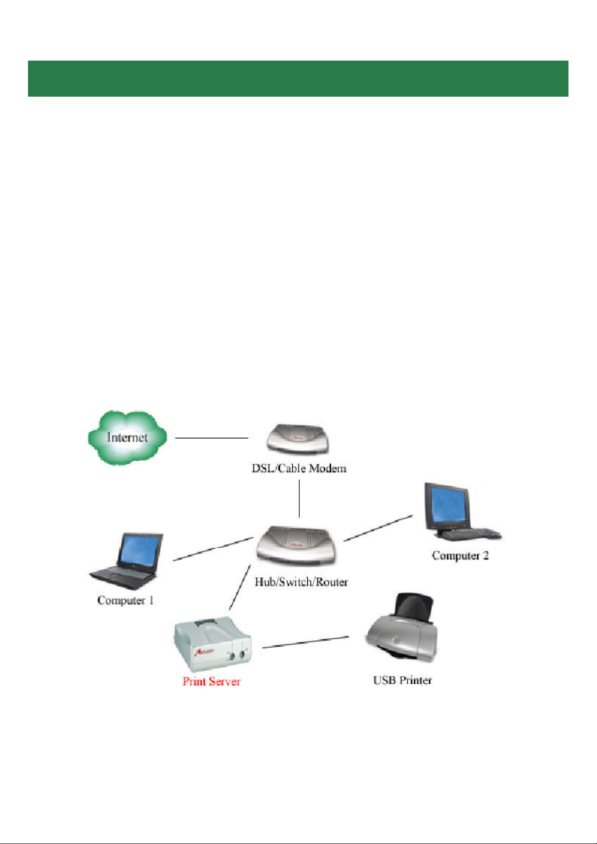
Step 1Connect one end of the Ethernet cable to the RJ-45 port of the Print Server
and attach the other end of the cable to a hub/switch/router . See Fig. 1.1
Step 2 Make sure the printer is powered OFF, then connect one end of the USB cable
to the USB port of the Print Server and attach the other end of the cable to the USB
port of the printer.
Step 3 Turn ON the printer .
Step 4 Plug one end of the power cord into the Print Server and the other end into an
electrical outlet.
Fig. 1.1
Page 3
Section 2
Configuring Client IP Address
Note: The default IP address of the Print Server is 192.168.1.254 with a subnet mask
of 255.255.255.0 The Print Server must be on the same subnet as your network in
order for you to print through the Print Se rver. Follow the steps below to access the
Print Server’s Web Configuration Utility. If your network ID is already using the 19 2.
168.1.x segment, ski p to Section 3, Accessing the Web Configuration Utility.
For Windows 2000/XP
Step 1 On one of the computers in your
network, right-click on M y Network Places
on your desktop and right-click on Local
Area Connection.
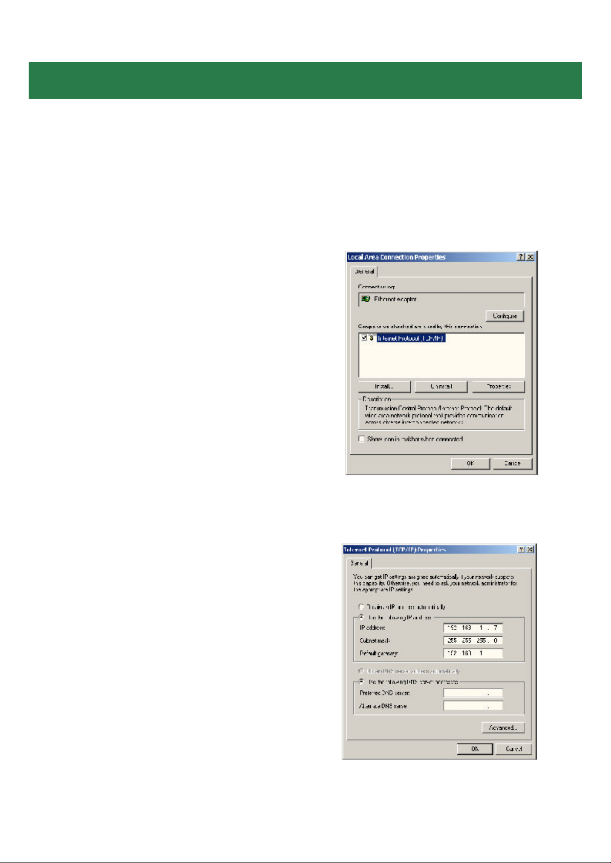
Step 2 Select Internet Protocol (T CP/IP)
and click Properties. See Fig. 2.1
Step 3 Write down your current network
settings including IP address, subnet
mask, and default gateway on a piece of
paper . You will need these information after
you have set up the print server in Section
3.
Step 4 Select Use the following IP ad-
dress and enter an IP address of 192.168.
1.x (where x is a number between 2 ~ 253
and is not currently assigned to any device
on your network).
Step 5 Enter 255.255.255.0 for the
Subnet mask.
Step 6 Enter the IP address of your De-
fault gateway. See Fig. 2.2
Step 7 Click OK and OK again.
Fig. 2.1
Step 8 Go to Section 3, Accessing the
Web Configuration Utility.
Fig. 2.2
Page 4
For Windows 95/98/ME
Step 1 Go to Start, Settings, Control
Panel, and double-click the Network icon.
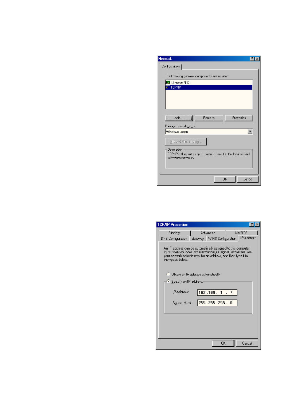
Step 2 Select T CP/IP and click
Properties. See Fig. 2.3
Step 3 Write down your current network
settings including IP Address and Subnet
M ask on a piece of paper. You will need
these information after you have set up the
print server in Section 3.
Step 4 Select Specify an IP address and
enter an IP address of 192.168.1.x (where
x is a number between 2 ~ 253 and is not
currently assigned to any device on your
network).
Step 5 Enter 255.255.255.0 for the
Subnet mask. See Fig. 2.4
Step 6 Click OK and OK again.
Step 7 Restart the computer if you are
prompted to do so.
Step 8 Go to Section 3, Accessing the
Web Configuration Utility.
Fig. 2.3
Fig. 2.4
Page 5
Section 3
Accessing the Web Configuration Utility
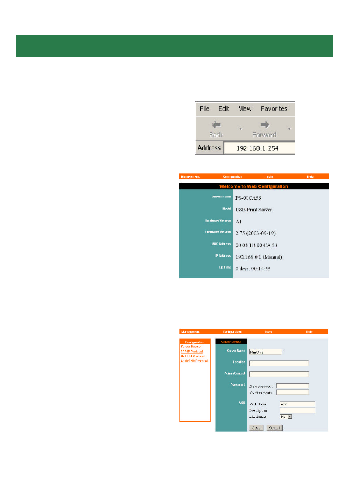
Step 1 Open the web browser and type the
default IP address of the Print Server: 192.
168.1.254 See Fig. 3.1
Step 2 The Welcome screen will appear .
See Fig. 3.2
Fig. 3.1
Step 3 Click on Configuration. You may
rename the Print Server name and Port
name or leave them with the default.
Step 4 Write down on a piece of paper the
Port name you want to use. Be sure to
click Save when you are done editing the
names. See Fig. 3.3
Fig. 3.2
Fig 3.3
Page 6

Step 5 Click on T CP/IP Protocol under
Configuration. See Fig. 3.4
Step 6 You can manually assign an IP ad-
dress and subnet mask to allow the Print
Server to be on the same subnet as your
network, or you can choose to obtain an IP
address automatically by RARP, BOOT P,
or DHCP.
Note: This Installation Guide uses the
default IP address as an example.
Step 7 Write down on a piece of paper the
IP address for the Print Server you want to
use. Be sure to click Save when you are
done configuring the settings.
Step 8 Close the web browser .
Step 9 If you have changed your
computer’s IP address in order to access
the web configuration utility, you can now
change the settings back to your original
settings.
Fig. 3.4
Section 4
Adding Printer
For Windows 2000/XP
Step 1 Go to Start, Settings, Printers.
(Printers and Faxes for XP) and select
Add Printer.
Step 2 Click Next at the Add Printer Wiz-
ard.
Step 3 Select Local Printer, uncheck the
Automatically detect and install my
Plug and Play printer check box, and
click Next. See Fig. 4.1
Fig. 4.1
Page 7

Step 4 Select Create a new port. At the
drop-down menu, select Standard T CP/IP
Port and click Next. See Fig. 4.2
Step 5 Click Next at the Add Standard
T CP/IP Printer Port Wizard.
Step 6 Type in the IP address of the Print
Server and the port name you have written
down on the piece of paper in Section 3
and click Next. See Fig. 4.3
Fig. 4.2
Step 7 Select Custom then click on Set-
tings. See Fig. 4.4
Fig 4.3
Fig. 4.4
Page 8

Step 8 Select LPR for the Protocol, enter
the Port Name in the Queue Name field,
and click OK. See Fig. 4.5
Step 9 Click Next.
Step 10 Click Finish.
Step 11 Select the manufacturer and
model of your printer and click Next.
Fig. 4.5
Note: If your printer is not on the list, click
Have Disk, insert the printer driver disk
that came with your printer , and click Next.
See Fig. 4.6
Step 12 If a driver for the printer is already
installed, select Keep existing driver and
click Next.
Step 13 Type in a name for your printer
and click Next. For Windows 2000, select
if you want to set this printer as the default
printer. See Fig. 4.7
Step 14 Select if you want to print a test
page and click Next.
Step 15 Click Finish.
Fig. 4.6
Fig. 4.7
Page 9

For Windows 95/98/ME
Step 1 Go to Start, Settings, Control
Panel, and double-click on Network.
Step 2 Click Add.
Step 3 Select Client and click Add. See
Fig. 4.8
Step 4 Click Have Disk.
Step 5 Insert the provided CD into the CD-
ROM drive.
Step 6 Click Browse and browse to your
CD-ROM drive.
Step 7 Select the letter of your CD-ROM
drive, double-click on the lpr folder, select
lpr.inf, and click OK. See Fig. 4.9
Fig. 4.8
Step 8 Click OK to accept the location of
the LPR file. See Fig. 4.10
Step 9 Click OK.
Step 10 Select LPR for T CP/IP Printing
and click Properties. See Fig. 4.11
Step 11 Click Add Port.
Fig. 4.9
Fig. 4.10
Fig. 4.11
Page 10

Step 12 Type in the IP address of the
Print Server and the port name you have
written down on the piece of paper in Section 3 and click OK. See Fig. 4.12
Step 13 The IP address and the port
name will be displayed in the port list.
Click OK.
Step 14 Click OK.
Note: Windows 98 may prompt you for the
Windows 98 CD-ROM. Insert the Windows
98 CD, and type in D:\Win98 (where D is
the letter of your CD-ROM drive) and click
OK. See Fig. 4.13
Restart the computer if you are prompted
to do so.
Fig. 4.12
Step 15 After your computer is restarted,
go to Start, Settings, Printers, Add
Printer.
Step 16 Click Next at the Add Printer
Wizard.
Step 17 Select Network Printer and click
Next.
Step 18 Click Browse.
Step 19 Browse to the Printer Port, high-
light it, and click OK. See Fig. 4.14
Step 20 Verify the Network path is
correct, select if you print from MS-DOSbased programs, and click Next.
Fig. 4.13
Fig. 4.14
Page 11

Step 21Select the manufacturer and model
of your printer and click Next.
Note: If your printer is not on the list, click
Have Disk, insert the printer driver disk
that came with your printer , and click Next.
See Fig. 4.15
Step 22 If a driver for the printer is already
installed, select Keep existing driver and
click Next. See Fig. 4.16
Fig. 4.15
Step 23 Type in a name for your printer ,
select if you want to set it as the default
printer , and click Finish. See Fig. 4.17
Fig. 4.16
Fig. 4.17
Page 12

Section 5
Using the Web Configuration Utility
You can use the Web Configuration Utility to configure the settings for your
Print Server . There are four sections to choose from: Management, Configu-
ration, Tools, and Help.
Note: As an option, you can also use the Print Server Admin utility (PS Admin) in-
cluded in the provided CD to manage your Print Server . Please refer to the User’s
Manual in the CD for installation and operation procedures for the PS Admin.
Step 1 Open the web browser and type in
the IP address of the Print Server .
Step 2 On the Welcome screen select the
section you want to view.
Ma nagement
System Status: displays general information about the Print Server. See Fig. 5.1
Server Name
Model
Hardware Version
Firmware Version
MAC Address
IP Address
Up Ti me
Click Refresh to obtain the latest
information.
Printer Status: displays general information about the Printer. See Fig. 5.2
Printer Name
Printer Status
Fig. 5.1
Click Refresh to obtain the latest
information.
Fig. 5.2
Page 13

Configuration
Server Device: Configures the Print
Server properties. See Fig. 5.3
Server Name: Assign a name to the Print
Server or keep the default.
Location: (optional) Indicate where the
Print Server is located.
Admin Contact: (optional) Indicate the
administrator for the Print Server.
Password: Password for accessing the
Print Server.
USB Port Name: Assign a name for the
USB Port.
Description: (optional) Brief descri ption
for the USB port.
PJL Printer: This feature supports
Hewlett-Packard PJL (Printer Job
Language) standard for bi-directional
printing.
Fig. 5.3
Click Save to update any changes you
have made.
T CP/IP Protocol: Configures the TCP/IP
properties of the Print Server. See Fig. 5.4
IP Address: Assign an IP address to the
Print Server or keep the default.
Subnet M ask: Assign a subnet mask to
the Print Server or keep the default.
Default Gateway: Enter the IP address of
the Default Gateway of your network.
IP Assignment: Choose either to manually
assign an IP address to the Print Server , or
automatically obtain an IP address by
RARP, BOOT P, or DHCP.
Click Save to update any changes you
have made.
Fig. 5.4
Page 14

NetBEUI Protocol: Configures the settings for NetBEUI printing. See Fig. 5.5
Workgroup: Enter the name of your
workgroup
M aximum Connected Stations: Set the
maxi mum number of stations that are allowed to connect to the print server at the
same ti me.
M aximum Number of Sessions: Set the
maxi mum number of print sessions that are
allowed to print at one ti me.
Click Save to update any changes you
have made.
AppleTal k Protocol: Configures the settings for AppleTalk printing. See Fig. 5.6
Fig. 5.5
AppleTal k Zone: Enter the name of your
zone.
Printer Type: Enter your printer type
PostScript Level: Select the postscri pt
level
Font Group: Select the font group
Click Save to update any changes you
have made.
Tools
Print Test: Prints an ASCII test page from
the Print Server to the printer . Your USB
printer must support Native DOS mode
printing. Click Test to print the test page.
See Fig. 5.7
Fig. 5.6
Fig. 5.7
Page 15

Reset: Restart the Print Server . Click Yes
to restart the Print Server. See Fig. 5.7
Factory Reset: Reset all settings to factory default and restart the Print Server .
The IP address of the Print Server will
return to the factory default of 192.168.1.
254 Click Yes to Factory Reset and restart
the Print Server. See Fig. 5.8
Fig. 5.7
Help
About: Displays the version number of the
Print Server: See Fig. 5.9
Fig. 5.8
Fig. 5.9
Page 16

Section 6
Product Specifications
Printer Connection
Printer Interface: One USB Port (ver 1.1)
Network Connection
Network Interface: RJ-45 connector for 10Base-T or 100Base-TX shielded
Network Standards: IEEE 802.3 10Base-T Ethernet, IEEE 802.3u 100Base-TX
Fast Ethernet
Network Data Transfer Rate: 10/100 Mbps
Network Protocols
Ethernet Frame Types: 802.2, 802.3, Ethernet II, SNAP (auto-switching)
Transport Protocols: TCP/IP, NetBEUI, AppleTalk
T CP/IP Protocols Supported: BOOTP, SNMP, Telnet, TFTP, FTP, LPD, RARP,
DHCP
Ma nagement and Diagnostics
Standard: SNMP
M IBs: MIB-II (RFC 1213)
Diagnostic LED Indicators: PW, LAN, USB
Environmental a nd Physical
Power Supply: External power supply providing 5VDC input
Operating Temperature: 0 degree C to 50 degree C (32 to 122 F)
Storage Temperature: -25 degree C to 55 degree C (-13 to 131 F)
Humidity: 5% to 95%, non-condensing
Emissions: FCC Class B, CE Class B
Page 17

Section 7
Technical Support
E-mail: support@airlinkplus.com
Toll Free: 1-888-746-3238
Web site: www.airlinkplus.com
 Loading...