

Page 1

Wireless G 2.4GHz 500mW Outdoor AP
Model: APO1000/APO1010
Quick Installation Guide
V.1.0
Page 2

Preface
The 802.11 b/g compliant Airlink101® APO1000/APO1010 is an outdoor high power wireless access point that can be used
for five different purposes in three different modes. In the AP mode, it can be deployed either as traditional fixed wireless
Access Point (AP), or combination of AP and WDS (AP+WDS). In the WDS mode, it’s only used to expand or bridge Ethernet
networks and deployed as a main base, relay based or remote base station. In the CPE (Customer Premises Equipment)
mode, it connects to Wireless Internet Service Provider’s (WISP) outdoor network via wireless WA N gateway to access to
Internet. In the Client Bridge + Universal Repeater mode, it connects to Wireless Internet Service Provider’s (WISP) outdoor
network via wireless or wired bridge to access to Internet
The die-cast sealed APO1000/APO1010is compact in size and compliant with IP68 weatherproof standard. It comes with a
mounting kit to mount on pole or wall. It is suitable for both indoor and outd oor usage with its 500mW output power, which is
higher than a typical indoor AP (100mW).
This Quick Installation Guide provides instructions and refe rence material for getting started with APO1000/APO1010. This
guide will also show you how to connect APO1000/APO1010 to other network devices.
Package Contents
The standard package contents of APO1000/APO1010 :
APO1000/APO1010 x 1
Quick Installation Guide x 1
CD-ROM (with User Manual and QIG) x 1
PoE Adapter (PSE) with AC Cable x 1
Mounting Kit x 1
It is highly recommended to use all the supplies in the package instead of substit uting any components by other
suppliers to guarantee best performance.
Page 3
System Overview
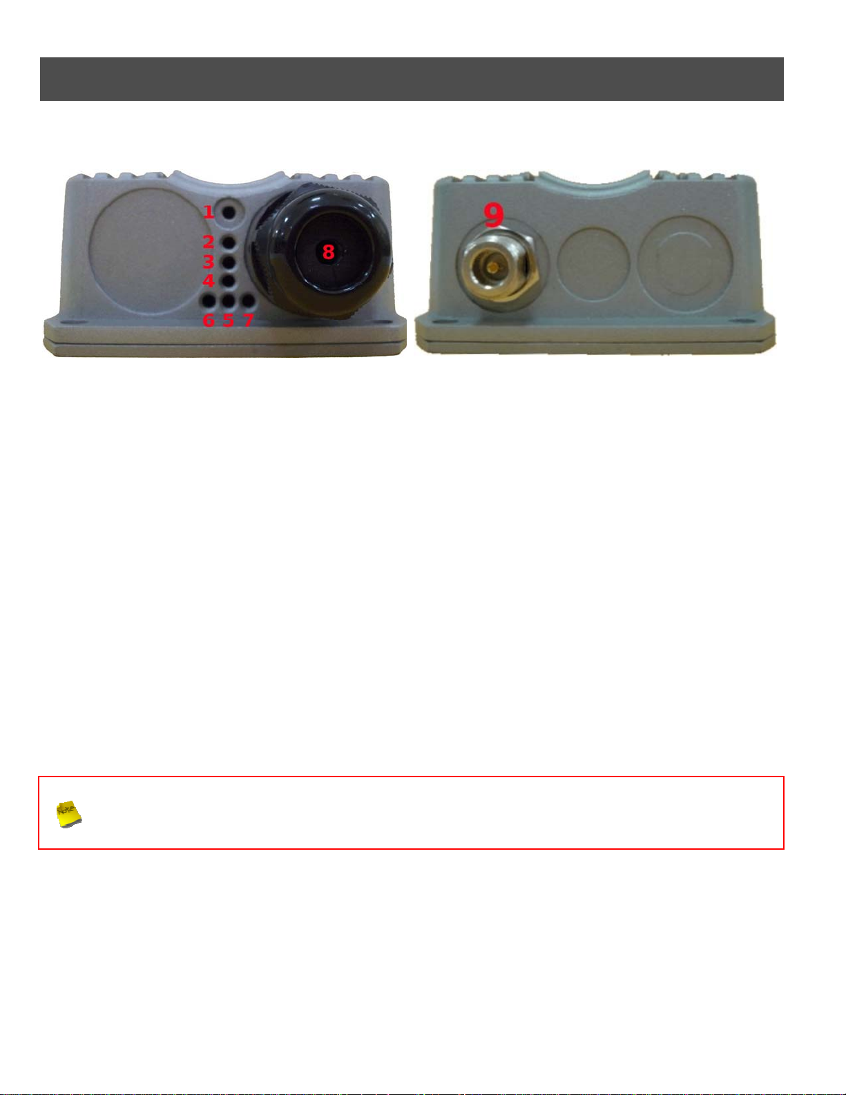
¾ APO1000
Front Panel Rear Panel
1. Reset Button : System reboot button press until LED flashed and release for system reboot or for reset to
factory default press, LED flashes keep pressing until LED becomes static
2. Power : Red LED ON indicates power on, and OFF indicates power off
3. Signal Strength : Yellow LED ON indicates Low Signal (CPE Mode)
4. Signal Strength : Green LED ON indicates Normal Signal (CPE Mode) or (WDS Mode only)
5. Signal Strength : Green LED ON indicates High Signal (CPE Mode) or (AP Mode only)
6. WLAN : Green LED BLINKING indicates Wireless ON, and BLINKING quickly indicates Wireless
Transmit quickly.
7. Ethernet : Green LED ON indicates connection, OFF indicates no connection
8. PoE Connector : For connecting to PSE
9. N-Type Conn ector : For connecting to N-Ty pe antenna
In CPE Mode, the LED 3 ON indicates the signal Low ( Signal <= 10 RSSI); the LED 3 and 4 ON indicate the
signal Normal (10 < Signal <=40 RSSI); the LED 3, 4 and 5 ON indicate the signal High ( Signal > 40 ).
Only LED 4 ON indicates the operating mode is WDS Mode; only LED 5 ON indicates the operating mode is
AP Mode.
2
Page 4
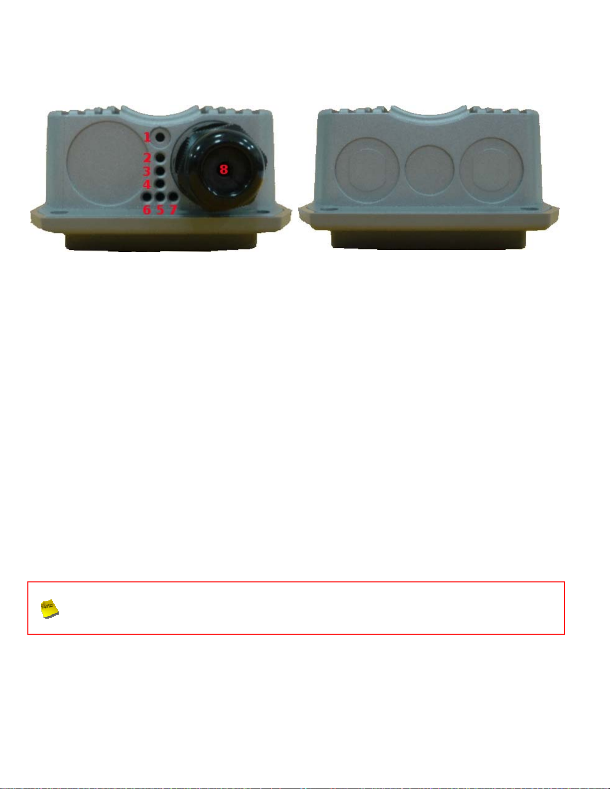
¾ APO1010
Front Panel Rear Panel
1. Reset Button : System reboot button press until LED flashed and release for system reboot or for reset
to factory default press, LED flashes keep pressing until LED becom es static
2. Power : Red LED ON indicates power on, and OFF indicates power off
3. Signal Strength : Yellow LED ON indicates Low Signal (CPE Mode)
4. Signal Strength : Green LED ON indicates Normal Signal (CPE Mode) or (WDS Mode only)
5. Signal Strength : Green LED ON indicates High Signal (CPE Mode) or (AP Mode only)
6. WLAN : Green LED BLINKING indicates Wireless ON, and BLINKING quickly indicates Wireless
Transmit quickly.
7. Ethernet : Green LED ON indicates connection, OFF indicates no connection
8. PoE Connector : For connecting to PSE
In CPE Mode, the LED 3 ON indicates the signal Low ( Signal <= 10 RSSI); the LED 3 and 4 ON indicate the
signal Normal (10 < Signal <=40 RSSI); the LED 3, 4 and 5 ON indicate the signal High ( Signal > 40 ).
Only LED 4 ON indicates the operating mode is WDS Mode; only LED 5 ON indicates the operating mode is
AP Mode.
Page 5
Hardware Installation
Please follow the steps mentioned below to install the hardware of APO1000/APO1010 :
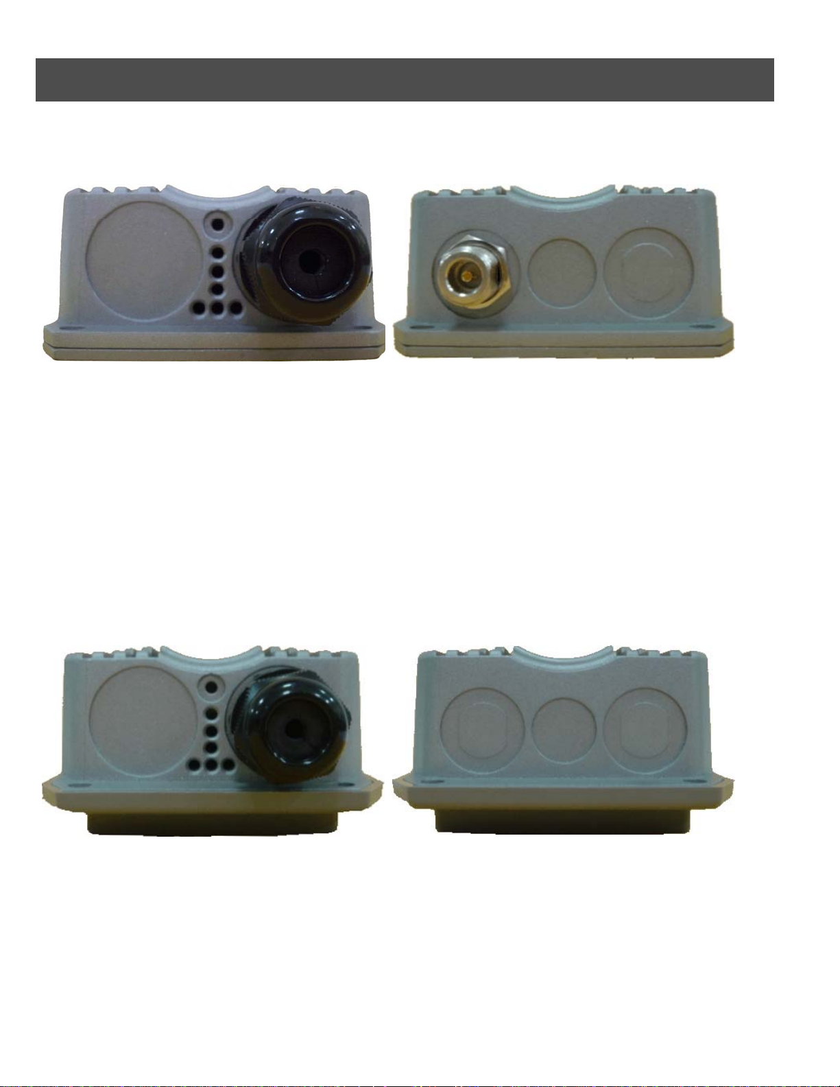
¾ APO1000
Front Panel Rear Panel
Î Connect N-type antenna to the N-type connector on the rear panel.
Î Connect Power Injector to the PoE connector on the front panel.
Î Connect an Ethernet cable to the Power Injector and the other end to a computer.
Î Source power to Power Injector in order to supply power to APO1000
¾ APO1010
Front Panel Rear Panel
Î Connect Power Injector to the PoE connector on the front panel.
Î Connect an Ethernet cable to the Power Injector and the other end to a computer.
Î Source power to Power Injector in order to supply power to APO1010
4
Page 6

Getting Started
APO1000/APO1010 supports web-based config uration. Upon the completion of hardware installation, APO1000/APO1010
can be configured through a PC or Laptop by using its web browser such as Internet Explorer or Mozilla Firefox.
¾ Default IP Address : 192.168.2.254
¾ Default IP Netmask : 255.255.255.0
¾ Default User Name and Password :
The default user name and password for both root manager account and admin manager account are as follows :
Mode CPE Mode AP Mode WDS Mode
Management Account
User Name
Password
Root
Account
root admin root root root
default admin default default default
Admin
Account
Root
Account
Root
Account
Client Bridge +
Universal Repeater Mode
Root
Account
Step
IP Segment Set-up for Administrator's PC
Set the IP segment of the administrator's computer to be in the same range as APO1000/APO1010 for accessing the
system. Do not duplicate the IP Address used here with IP Address of APO1000/APO1010 or any other device within the
network
Example of Segment :
The valid range is 1 ~ 254 and 192.168.2.254 shall be avoided because it is already assigned to APO1000/APO1010.
192.168.2.10 is used in the example below.
¾ IP Address : 192.168.2.10
¾ IP Netmask : 255.25 5.255.0
Launch Web Browser
Launch web browser to access the web management interface of system by entering the default IP Address,
http://192.168.2.254
, in the URL field, and then press Enter.
Page 7
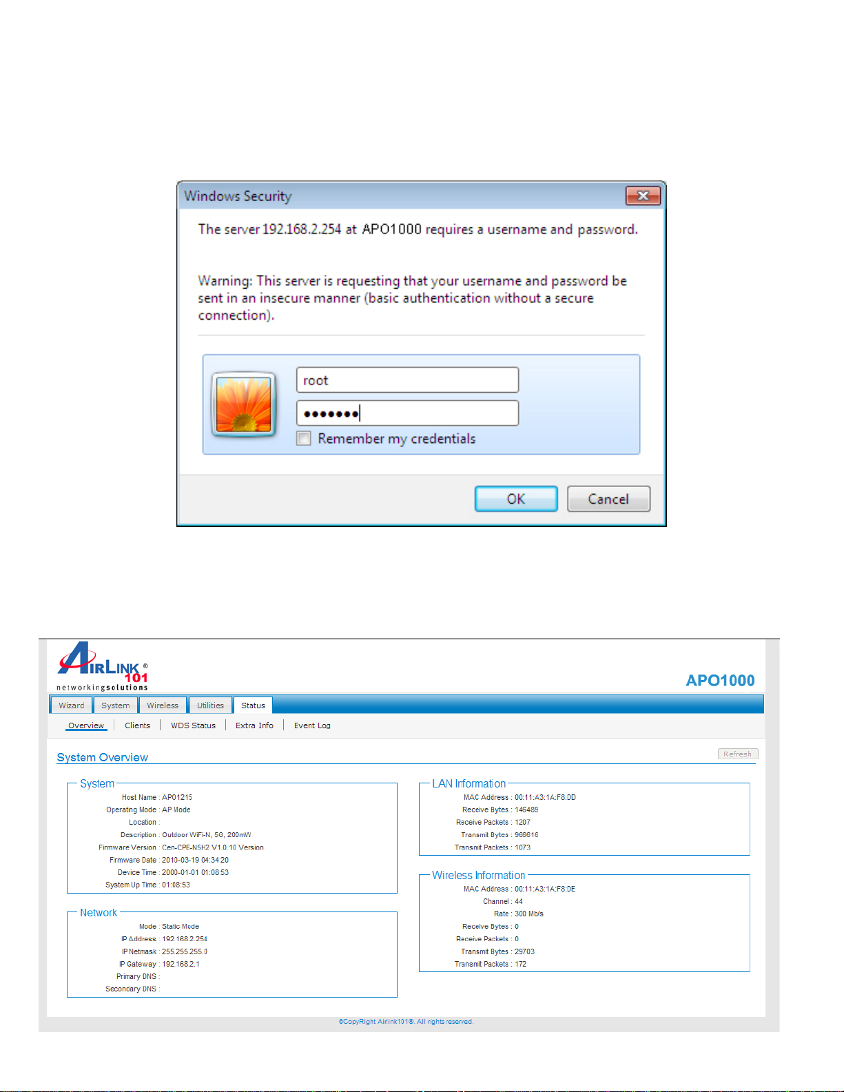
System Login
The network manager Login Page then appears.
Enter “root” for user name and “default” for password, and then click OK to login to the system.
Login Success
System Overview page will appear after successful login.
6
Page 8

Quick Setup
APO1000/APO1010 is a multiple mode system which can be configured either as a gateway or an access point as desired.
This section provides a step-by-step configuration procedure for basi c installation on AP Mode, WDS Mode and CPE
(Wireless Bridge) Mode and Client Bridge + Universal Repeater.
¾ Setup In AP Mode
APO1000
Step 1 : Mode Confirmation
Ensure the Operating Mode is currently at AP mode; the web management UI can be viewed at the Status section under
the System Overview page.
Step 2 : Change Password
Click System -> Management and then Management Setup page appears.
Page 9

There can change root and admin manager account. Enter a new password, an d verify it again in the New Pas sword
and Check New Password field respectively. Click Save button, and proceed with the following steps.
Step 3 : LAN IP Settings
Click System -> LAN, and then Network Setup page appears.
Enable “Static IP” and “DNS”, and enter the related informations in the field marked with red asterisks. Click Save button
to save the settings.
Step 4 : Time Zone settings
Click System -> Time Server, and then T ime Server Setup pa ge appears.
Enable “Setup Time Use NTP”, and then enter the related information. Click Save button to save the settings.
8
Page 10

Step 5 : ESSID Settings
Click Wireless -> Virtual AP Setup, and then VAP Setup page appears.
Click “Edit” and then VAP0 Setup page appears.
Set up the broadcasting ESSID for easily identifying the system when device is trying to associate the service. Click
Save button to save settings
Step 6 : Security Settings
In VAP0 Setup page, select WEP in “Security Type“ pull down menu. The WEP setting field will shown up immediately.
Page 11

Enter the WEP key information required in the WEP settings field, and the same information will also be used to set up
devices which will then be using APO1000/APO1010's services.
Click Reboot to activate all settings configured so far.
Congratulation! The AP mode is now successfully configured.
10
Page 12

¾ Setup In WDS Mode
A
PO1000
Step 1 : Mode Confirmation
Ensure the Operating Mode is currently at WDS mode; the web management UI can be viewed at the Status section
under the System Overview page.
Step 2 : Change Password
Click System -> Management and then Management Setup Configuration p ag e appears.
There can change root and admin manager account. Enter a new password, an d verify it again in the New Pas sword
and Check New Password field respectively. Click Save button, and proceed with the following steps.
Page 13

Step 3 : LAN IP Settings
Click System -> LAN, and then Network Setup page appears.
Enable “Static IP” and “DNS”, and enter the related information in the field marked with red asterisks. Click Save button
to save the settings.
Step 4 : Time Zone settings
Click System -> Time Server, and then T ime Server Setup pa ge appears.
Enable “Setup Time Use NTP”, and then enter the related information. Click Save button to save the settings.
Step 5 : Enable WDS Peer's MAC Address
Click Wireless -> WDS Setup, and then WDS Setup page appears.
Enable “WDS Peer's MAC Addre s s”, and then enter the related information. Click Save button to save the settings.
12
Page 14

Setting WDS link, you need verify “Peer's MAC Address”, “Channel” and “Security Type” first. The “Channel”
and “Security Type” must be the same
Step 6 : Wireless General Settings
Click Wireless -> General Setup, and then General Setup page appears.
Select the “Channel” and “Transmit Rate Control” information required in the General Setup field. The information must
the same the other WDS device.
Try to select fix “Transmit Rate Control” will be get better throughput. “Tx Power” also effect throughput. More
advanced setting see User Manual
Click Reboot to activate all settings configured above.
Congratulation! The WDS mode is now successfully configured.
Page 15

¾ Setup In CPE (Customer Premises Equipment) Mode
A
PO1000
Step 1 : Mode Confirmation
Ensure the Operating Mode is currently at CPE mode; the web management UI can be viewed at the Status section
under the System Overview page.
Step 2 : Change Password
Click System -> Management and then Management Setup page appears.
There can change root and admin manager account. Enter a new password, an d verify it again in the New Pas sword
and Check New Password field respectively. Click Save button, and proceed with the following steps.
14
Page 16

Step 3 : LAN IP Settings
Click System -> LAN, and then LAN Setup page appears. Enter the “IP Address” and “IP Netmask” of the LAN Setup.
Step 4 : Time Zone settings
Click System -> Tim e Server, and then Time Server S etup page appears. Enable “NTP Client”, and then enter the related
information. Click Save button to save the settings.
Step 5 : WAN IP Settings
Click System -> WAN, and then WAN Setup page appears.
Page 17

Enable “Static IP”, and then enter the related information (Default WAN IP is 192.168.1.254)
Click Save button to save the settings.
Step 6 : Site Survey
Click Wireless -> Site Survey, and then Station Site Surv ey page appears. The system will automatically scan and
display the scan results of all AP existing near by the system.
Below depicts an example for scanning result.
Step 7 : Select AP to be Associated
Search for the AP to be associated with from the Scan Result list provided in Step 6; use AP00 as an example here
where the AP is encrypted via WEP security type.
Step 8 : Wireless General Setup
16
Page 18

Click Select button of the AP00, and related information will display in Wireless General Setup page.
Enter the information required in the Wireless General Setup page. Information to be entered shall be exactly the same
as configured in the AP00 AP.
Click Save to save the settings.
Click Reboot button to activate all settings configured above.
Congratulation! The CPE mode is now successfully configured.
Page 19

¾ Setup In Client Bridge + Universal Repeater Mode
A
PO1000
Step 1 : Mode Confirmation
Ensure the Operating Mode is currently at Client Bridge + Universal Repeater mode; the web management UI can be
viewed at the Status section under the System Overview page.
Step 2 : Change Password
Click System -> Management and then Management Setup page appears.
There can change root and admin manager account. Enter a new password, an d verify it again in the New Pas sword
and Check New Password field respectively. Click Save button, and proceed with the following steps.
18
Page 20

Step 3 : LAN Settings
Click System -> LAN, and then LAN Setup page appears. Enter the “IP Address” and “IP Netmask” of the LAN Setup.
Step 4 : Time Zone settings
Click System -> Time Server, and then T ime Server Setup pa ge appears. Enable “NTP Client”, and then enter the
related information. Click Save button to save the settings.
Page 21

Step 5 : Site Survey
Click Wireless -> Site Survey, and then Station Site Surv ey page appears. The system will automatically scan and
display the scan results of all AP existing near by the system.
Below depicts an example for scanning result.
Step 6 : Select AP to be Associated
Search for the AP to be associated with from the Scan Result list provided in Step 3; use AP00 as an example here
where the AP is encrypted via WEP security type.
Step 7 : Wireless General Setup
Click Select button of the AP00, and related information will display in Wireless General Setup page.
Enter the information required in the Wireless General Setup page. Information to be entere d shall b e exactly the same
as configured in the AP00.
Click Save to save the settings.
Step 8 : Repeater AP's SSID & Security Settings
20
Page 22

Click Wireless -> AP Setup, and then AP Setup page appears.
Setup the broadcast SSID for easy identification of the system when device is trying to associate the service. The default
SSID is “Repeater_AP”.
Select WEP in “Security Type“ drop-down list. The WEP setting field will show up immediately. Enter the WEP key
information required in the WEP settings field, the same information will also be used to set up devices using
APO1000/APO1010's services.
Click Reboot to activate all settings configured above.
Congratulation! The Client Bridge + Universal Repeater mode is now successfully configured.
Page 23

Technical Support
E-mail: support@airlink101.com
Toll Free: 1-888-746-3238
Web Site: www.airlink101.com
*Theoretical maximum wireless signal rate derived from IEEE standard 802.11 specifications. Actual data throughput will vary. Network
conditions and environmental factors, including volume of network traffic, building materials and construction, mix of wireless products
used, radio frequency interference (e.g., cordless telephones and microwaves) as well as network overhead lower actual data throughput
rate. Specifications are subject to change without notice. Photo of product may not reflect actual content. All products and trademarks are
the property of their respective owners. Copyright ©2010 Airlink101®
22
 Loading...