

Page 1
Application Note
for connecting the
AirLink Raven CDPD Modem
to Ethernet Devices using the
IP 5200 from DCB
March 2002
AirLink Communications, Inc.
Confidential Material - Not For Redistribution
Page 2

AirLink Application Notes
THIS DOCUMENT CONTAINS CONFIDENTIAL MATERIAL AND
IS NOT INTENDED FOR REDISTRIBUTION.
Information contained herein is the property of AirLink Communications, Inc. and is produced for the
purpose of detailing technology developed by AirLink Communications, Inc. and its employees.
Reproduction or distribution of this document without the express written consent of AirLink
Communications, Inc. is strictly prohibited. This document is subject to change without notice.
Copyright AirLink Communications, Inc, 2001. All rights reserved.
Please send comments to:
Email: pubs@AirLink.com
Fax: 510-226-4299
Phone: 510-266-4200
Post: AirLink Communications, Inc.
Attention: Technical Publications Dept.
472 Kato Terrace
Fremont, CA 94539
AirLink Communications Page 2 www.airlink.com
Page 3

AirLink Application Notes
CONTENTS
1. OVERVIEW.....................................................................................................................................4
2. INTERNET (TCP/IP) CONNECTION VIA CDPD.....................................................................4
3. ETHERNET DEVICE & IP5200 CABLING & INSTALLATION.............................................4
4. IP5200 CONFIGURATION ..........................................................................................................5
5. AIRLINK RAVEN CDPD MODEM CONFIGURATI ON.........................................................11
AirLink Communications Page 3 www.airlink.com
Page 4
AirLink Application Notes
Frame
3 1 2
1. Overview
This document describes how to connect the AirLink Raven CDPD Modem to the IP5200 AsyncRouter from Data Communications for Business (DCB). Information on the IP5200 and DCB is available
at www.dcbnet.com . Additional information about AirLink Communications products is available at
www.AirLink.com
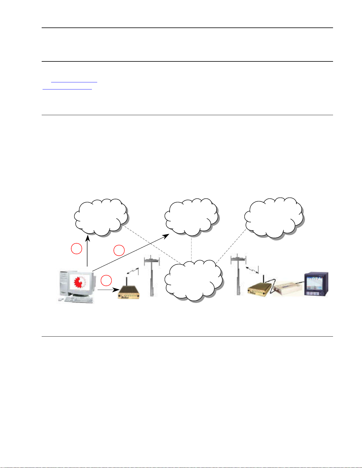
2. Internet (TCP/IP) Connection via CDPD
Normally, remote access to an IP 5200 is done via Dialup Telephone Line. When using CDPD, remote
access to is done via a TCP/IP connection to the CDPD Network (ie: Internet) an d the use of a CDPD
Modem connected to a DCBNet IP5200 Single-Port Async-Router.
On the HOST side, access to the CDPD Network could be made using any of the following means:
1. Using a Frame Relay connection into the CDPD Network
2. Using the public Internet
3. Using another CDPD Modem connected to the Host System
Relay
Internet
Other
CDPD
Networks
Local
CDPD
Network
3. Ethernet Device & IP5200 Cabling & Installation
Setting up the Ethernet device (PC, RTU, PLC, etc) for communicating over CDPD is fairly
straightforward. All the same configuration settings used for a LAN installation apply to a CDPD
installation. Since the device is actually sitting on a very small LAN, (just the device and the IP5200), the
IP Address would be a private IP, such as: 192.168.1.101. The IP5200 would have an Address in the
same range, such as: 192.168.1.100.
DNS, FTP, SMTP, and Email settings would be for servers visible to the public Internet or in the
case of Frame Relay connections to the CDPD network – IP Addresses visible to the Frame Relay cloud.
(See your Network Administrator or Carrier for more details on which Addresses or server names to use).
When the device initiates Ethernet traffic (by either sending an email or starting an FTP session, etc),
the router will dial the CDPD modem and establish a PPP connection. The CDPD Modem will supply the
router with its IP address, virtually becoming the router’s Internet Service Provider (ISP).
AirLink Communications Page 4 www.airlink.com
Page 5

AirLink Application Notes
192.168.1.101
Ethernet
RS232
192.168.1.100
166.x.x.1
166.x.x.1
IP Address of CDPD Modem becomes Public Side
IP5200 is both a Dial
-on-
Demand
Private Class
-
C IP Addresses are on same
At the ‘
’ page,
select the ‘Internet Access’
tton
takes you to the Main Menu.
10
100 RJ-45 1 2 3 4 5
Power
Diagram of how to connect the IP5200 Router and CDPD modem:
Router and Network Firewall
Crossover
Cable
Address of Router during PPP negotiations.
subnet using subnet mask 255.255.255.0.
4. IP5200 Configuration
Setting up the IP5200 should be done using the instructions provided by DCB. The DIP Switches
on the Ethernet side of the unit are used for handshake and flow control and should be set as follows:
Jack £ £ ¤ ¤ ¤
The following screen shots cover the device settings specific to connecting to a CDPD Modem.
WWeellccoommee ttoo SSeettuup
button. The Configure bu
p
AirLink Communications Page 5 www.airlink.com
Page 6

You will need to set the Internet
LAN Settings, and
The Internet Access se
tup
screen for Ports 1 and 2 has
three requirements:
Multi
-
port Usage
Even though the
IP5200’s (2) serial
ports can be used for
link PPP, this is
not a feature that can
be used over CDPD
Account,
Dial-out Modem parameters.
AirLink Application Notes
- ‘Enable’ must be checked
- Tel -1 and Tel-2 should be
entered as shown
- Disconnect after Idle Time
should be set to ‘0’.
This will make sure the
IP5200 does not drop the
PPP connection when the
serial port is idle.
Multi-
network.
AirLink Communications Page 6 www.airlink.com
Page 7

LAN Configuration is actually
The LAN IP Address needs to be
different from the PLC address, but on
the same network and using the same
You will need to supply your own DNS
Settings. You can get these from your
Since there is no actual
Internet Account when
connecting to a CDPD
Modem, you can leave the
User Name, Password, and IP
Address allocated by ISP left
DNS should be the same as
entered on the previous
blank.
screen.
No Script File is needed.
AirLink Application Notes
referring to the Ethernet Port.
Net Mask.
CDPD carrier.
AirLink Communications Page 7 www.airlink.com
Page 8

Select the Modem option.
Selecting the ‘Properties’ button
will take you to the Modem
The Modem setup screen has four
Properties screen.
AirLink Application Notes
requirements:
- Initial String should be ‘AT’
- Serial Line Speed = 19200
- Dial Type = Other
- Dial String = ‘ATDT’
- Auto-answer commands are N/A
- Select ‘Save as Other’
AirLink Communications Page 8 www.airlink.com
Page 9

The Advanced Menu has a great
tures, most of which do
Most of these settings deal with the
firewall functions inside the
IP52000. Since there is only one
device on the Ethernet port, and it is
connected to a CDPD Modem, and
t really
To put the Ethernet port outside the
IP5200, you must set the device up
Select Enable Exposed
Computer Feature and
enter the IP of the Ethernet
device. In this case it is
many fea
not apply to this application.
not an ISP, the firewall is no
necessary.
as an Exposed Computer.
AirLink Application Notes
192.128.1.101.
AirLink Communications Page 9 www.airlink.com
Page 10

Checking to see if the
Go to the Port Status page
on the Main Menu and
button.
You can watch the Log for
entries and errors, and see
the Physical Link and PPP
atus right on the
You know right away if the
connection to the modem is
router works is easy.
Select the Dial-Up
Link st
screen.
AirLink Application Notes
working or not.
AirLink Communications Page 10 www.airlink.com
Page 11

AirLink Application Notes
5. AirLink Raven CDPD Modem Configuration
The following are the proper S-Register configurations for the AirLink Raven CDPD Modem when
connecting to the IP5200 for making a PPP connection. These settings can be made using Wireless ACE.
CDPD Parameters:
[S110] Device Port=12345
[\N] Side Preference=3
[S116] Service ID Preference=3
[S111] Service ID=0/0/0
[S112] Channel List Mode=2
[S113] Channel List=0,0,0,0,0
[3W] 3 Watt Booster Support=0
[*DSIDE] Disable Side Switch=0
[*CTSE] CTS CDPD Enable=0
[#X] Serial Debug Output=0
Modbus Parameters: N/A
Connection Parameters:
[S0] TCP Auto Answer Mode=0
[S7] TCP Establishment Timeout=20
[S50] Data Forwarding Timeout=1
[S51] Data Forwarding Character=0
[S53] Destination IP Address=10.0.10.0
[S53] Destination TCP/UDP Port=12345
[S53] Destination Connect Mode=T
[S210] AT Command Compatibility=1
[S211] Ignore DTR=0
[MD] Startup Mode Default=0
[MD] UDP Mode Default=0
[S60] Telnet Echo Mode=0
[S82] UDP Half Open Mode=0
[S83] UDP Half Open Timeout=5
[AIP] Allow Any UDP IP=1
[HOR] UDP Half Open Response=1
[S220] Break On TCP Connect=0
[S221] Delay Connect Response=0
[E] Command Echo=1
[V] Command Response Mode=1
[Q] Quiet Mode=0
[X] Call Progress Result Mode=0
[TCPT] TCP Inactive Timeout=1
[TCPS] Specify TCPT in Seconds=0
[TCPX] Allow TCP Suspension=0
[*DATZ] Disable Reset on ATZ=0
[*ENQ] Enable ENQ on TCP Connect=0
[DAE] Disable AT Esc Sequence=0
[RKEY] Radio Transceiver Keying=0
[IPL] IP List Dial=0
[*DU] Dial UDP Always=0
Friends List: (Optional)
COM Port Parameters:
[\Q] Flow Control=2
[S23] Baud Rate=19200
[S23] Data Bits=8
[S23] Parity=N
[S23] Stop Bits=1
AirLink Communications Page 11 www.airlink.com
 Loading...