

Page 1

PHOTOFACT*
Folder
O5BR-3O21B,
AIRLINE
MODELS
O5BR-3O24B,
O5BR-3O27A
o
Ul
OB
70
I)
O
KJ
VOLUME
CONTROL
ON-OFF
SWITCH
TRADE
NAME
SUPPLIER
TYPE
TUBES
POWER
TUNING
Alignment
Disassembly
Horizontal Sweep Circuit Adjustments
Parts
Photographs
Cabinet - Rear
Capacitor
Airline, Models 05BR-3021B,
Montgomery
SET
Television
Twenty
SUPPLY 1 10-115 Volts
RANGE—Channels 2 Thru
Instructions
Instructions
List
and
Description
Receiver
One
6, 7
10
12, 13, 15
View.
and
Alignment Identification
Ward
AC-60
13
BRIGHTNESS
CONTROL CONTROL
AIRLINE
Co.,
Cycle
05BR-3024B,
619
Chicago
10
4, 9
MODEL
Ave.,
INDEX
10
Voltage
„
05BR-3027A
05BR-3027A
Chicago,
RATING
Photographs
Chassis
RF
Tuner
Resistor
Schematic
Tube
Placement
and
HOLDf
Illinois
1. 8
(cont.)
- Top
and
Resistance
CONTROL
Amp.
® 115
View.
Inductor
Identification.
Charts
Measurements
Volts
AC
2?
CHANNEL
TUNING
CONTROL
3
7
.11,
14
2
5
.
8
8s
"O
m
DO
70
CO
O
to
HOWARD
"The listing
of any
case a recommendation, warranty
as
to the
parts have been
Inc.,
by the
"Reproduction
available replacement
quality
and
suitability
compiled
manufacturers
from
or
of the
use, without express permission,
of
information
or
guaranty
such
replacement
particular
W.
SAMS & CO.,
part
herein does
by
Howard
part.
furnished
to
type
of
replacement
of
not
W.
The
Howard
editorial
constitute
Sams & Co.,
numbers
of
W.
Sams & Co.,
part
listed"
or
pictorial
INC. • Indianapolis
in any
Inc.,
these
con-
tent.
In
any
manner,
the
use of the
Sams & Co., Inc.,
ternational Copyright
Union
DATE
information contained herein. Copyright
Indianapolis,
(1910)
by
Howard
11-51
is
prohibited.
Union.
W.
1,
Indiana
No
patent
Indiana,
All
rights
Sams & Co.,
liability
is
assumed
U. S. of
reserved
Inc."
1951
America. Copyright under
under Inter-American Copyright
Printed
with
by
Howard
in U. S. of
SET
respect
to
W.
In-
America
150
FOLDER
3
Page 2

THE
COOPERATION
RECEIVER
MAKES
IT
POSSIBLE
HI-LO
OF THE
BAND SWITCH SHOWN
MANUFACTURER
TO
BRING
YOU
IN HI
BAND POSITION
OF
THIS
THIS SERVICE
t-350
VDCCA)
350VDCCB)
X
ARE
BROKEN.
PAGE
2
A
PHOTOFACT STANDARD
©Howard
W.
NOTATION
Sams & Co., Inc. 1951
SCHEMATIC
Page 3
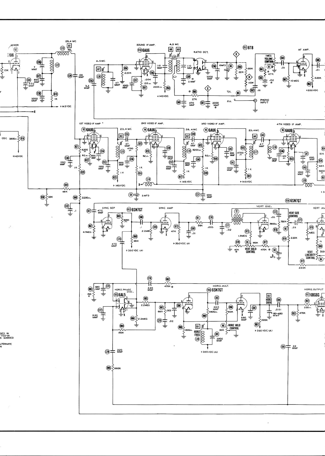
SOUND
®6AU6
IFAMP.
4-5
0 0
MC
®6T8
SED IN
'TED-IN
S
MARKED
Page 4

AUDIO
©6K6GT
OUTPUT
O5BR-3O21B,
AIRLINE
MODELS
O5BR-3O24B, O5BR-3O27A
Page 5

UJ
C/)
<
CO
co
o
O5BR-3O27A
MODELS
O5BR-3O24B,
AIRLINE
O5BR-3O21B,
Page 6
PAGE
4
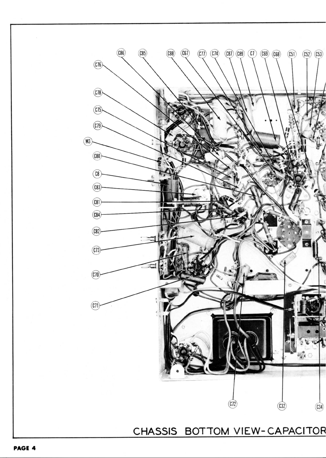
CHASSIS BOTTOM
VIEW-CAPACITOR
Page 7

o
Cn
CO
O
to
O
Ui
09
0
w
•^
0>
O
Ui
09
3D
I
O
O
10
jo
l-
•»
1
O
o
m
w
AND
ALIGNMENT IDENTIFICATION
PAGfc
9
Page 8

HORIZ.OUTPUT
1
TOP
VIEW
HORIZ.PUTOUT
VERT
OSC
VERT
AMR
O
Ul
09
JO
i
O
O
Ki
O
Ui
OB
0
10
*>
01
O
Ul
OJ
*
r 7
O
O
m
«"
TUBE
BOTTOM
VIEW
PLACEMENT CHART
PAGE
5
Page 9

The
end of
the
high
voltage
Remove
the
the
possibility
Note:
In
later
DUMMY
ANTENNA
Direct
ligh
tube
dummy
(V2) . Low
DUMMY
ANTENNA
Direct
High
ube
dummy
V2) . Low
DUMMY
ANTENNA
.01MFD.
High
of
o
Connect
two
schematic.
DUMMY
ANTENNA
.01MFD.
High
of
to
Use
frequency
DUMMY
ANTENNA
.01MFD.
High
of
to
Remove
the
Pre-set
the
With
the
switch
Check
to see
clockwise
.
Move
carriage
Connect
the
The
sweep generator
DUMMY
ANTENNA
Across antenna terminals
Two
120SJ
with
carbon
resistors
DUMMY
ANTENNA
Two
120S2
Across
with
carbon
resistors
high
voltage
.
converter tube, (V2),
of
productions
side
shield
side
shield
side
6AL5,
chassis.
matched
side
6AL5,
chassis.
modulated signal
side
6AL5,
chassis.
dummy
trimmer
is low
that
bar
synchronized
120ft
120(2
lead should
erroneous
indications
the
6J6, converter,
SIGNAL
GENERATOR
COUPLING
to an
ungroundec
floating
converter tube,
GENERATOR
converter
GENERATOR
GENERATOR
GENERATOR
the
GENERATOR
GENERATOR
over
side
to
chassis
SWEEP
COUPLING
to an
ungroundet
floating
over
tube,
side
to
chass
SWEEP
COUPLING
to pin 1
(cathodi
(V7).
Low
side
lOOKft
(-
1%)
SIGNAL
COUPLING
to pin 1
(cathode
(V7).
Low
side
SWEEP
COUPLING
to pin 1
(cathode!
(V7).
Low
side
converter tube
screws
as
band
position,
cores project 1.6ins.
down
7/64 inch, from
sweep voltage
output
lead
SWEEP
COUPLING
in
each
lead.
SWEEP
COUPLING
antenna
terminals
in
each
lead.
•'
ALIGNMENT INSTRUCTIONS
be
securely
taped
and
kept away
from
the
chassis.
Do not
VIDEO
IF
from
!
resistors
with
and
shown
should
its
socket
.
SIGNAL
GENERATOR
FREQUENCY
26.4MC
23.4MC
25MC
SWEEP
GENERATOR
FREQUENCY
24 MC
(10MC
SWEEP
GENERATOR
FREQUENCY
Not
used
SOUND
SIGNAL
GENERATOR
FREQUENCY
4.
SMC
(unmod.)
••
SOUND
60%
modulation
SWEEP
GENERATOR
FREQUENCY
4.
SMC
(450KC
SWP)
"
replace
in
figure
turn
the
out of the
extreme
from
be
terminated
SWEEP
GENERATOR
FREQUENCY
8
SMC
(10MC
SWP)
63MC
(10MC
SWPl
69MC
(10MC
SWP)
79MC
(10MC
SWP)
57MC
(10MC
SWP)
SWEEP
GENERATOR
FREQUENCY
213MC
(10MC
SWP)
207MC
(10MC
SWP)
201MC
(10MC
195MC
(10MC
SWP)
188MC
(10MC
SWP)
163MC
(10MC
177MC
(10MC
SWP)
and
has
been replaced
CHANNEL
GENERATOR
FREQUENCY
23MC
SWP)
26.75MC
GENERATOR
FREQUENCY
4.
(400%
IF
in
series
CHANNEL
IF
ALIGNMtNT
GENERATOR
FREQUENCY
4.
the
original tube
5.
tuner core
top,
the
signal generator
GENERATOR
FREQUENCY
GENERATOR
FREQUENCY
SWP)
SWP)
replace
it
with a 6J6
Any
DC
Common
OVERALL
MARKER
MARKER
AtlGNMENT USING
Any
and
MARKER
coils,
MARKER
83.25MC
87.75MC
61.25MC
65.75MC
67.25MC
71.75MC
77.25MC
81.75MC
55.25MC
59.75MC
MARKER
SMC
Mod.)
from
Point
450KC
SMC
carriage
then turn
by
turning tuning
with
its
211.25MC
215.75MC
205.25MC
209. 7 SMC
199.25MC
203.75MC
193 . 25MC
197. 7 SMC
187.25MC
191.75MC
181.25MC
185.75MC
175.25MC
179.75MC
CHANNEL
4
.5MC
CHANNEL
DC
Common
DC
Common
USING
sweep.
CHANNEL
TUNER
in its
LOW
characteristic
CHANNEL
(see note
HIGH
CHANNEL
(see note
ALIGNMENT
which
with a 12AT7.
CONNECT
VTVM
probe
to
PoinK^>.
to
chassis.
VIDEO
IF
RESPONSE
Any
PointX£>.
to
THAI
'ADJUSTMENT
Any
Vert.
pin
Low
AM
SIGNAL GENERATOR
B to B-. The
CONNECT
VTVM
probe
to
Poinl<§>.
to
chassis.
probe
to
Poinw£>.
to
Point^J.
FM
SIGNAL GENERATOR
Use
120%
Any
to
Vert. Amp.
Point4J>.
ALIGNMENT
socket.
to the
extreme
the low
band
BAND
ALIGNMENT
control
to the
horizontal
Vert. Amp.
6.
PoinKQX
to
above)
3
4
5
2
BAND
ALIGNMENT
13
above)
12
11
10
9
8
7
has pin 1
In
that event
CONNECT
SCOPE
Vert.
Amp.
Low
chassis.
CONNECT
SCOPE
Amp.
2 of
picture tube.
side
to
junction
sawtooth
CONNECT
SCOPE
Vert.
Amp.
Point<^>.
Low
chassis
Low
to
chassis.
top of its
oscillator
clockwise.
input
impedance,
CONNECT
SCOPE
Low
chassis.
"
CONNECT
SCOPE
Vert. Amp.
PoinK£>
Low
to
chassis.
removed.
ADJUST
Al,
A2
A3, A4
A5
CHECK
to
side
to
chassis.
of
these
ADJUST
A7,
AS
A9
voltage
to
side
.
to
side
travel.
core
This
of the
usually
to
side
to
side
use a
AND
remove
the
horizontal
This will
disable
12AT7
with
pin 1
Adjust
for
maximum deflection.
to
maintain 1 volt reading.
ADJUST
Check
If
necessary
response
ADJUST
A6
Adjust
AND
VTVM
two
resistors
is
Adjust
for
maximum
Adjust
for
zero reading. A positive
ng
will
be
obtained
OSCILLOSCOPE
in
scope
for
horizontal
ADJUST
A7,
A8
Disconnect
for
maximum
fie.
2.
A9
Reconnect
occurs
fig.
3.
amplitude
on
additional
four
is the
proper
ohms.
All,
A15,
position
for
horizontal deflection.
Adjust
cal
peaks
Adjust
ponse curve
Turn
appears
of
the low
response
A12
for
give
Adjust
with
Adjust
response curve
Turn
50%
check
sary
adjustment
over
oscilloscope
50
ADJUST
AID,
A12
A13
ADJUST
A14,
A16
A17
oscillator
tube
the
local
oscillator
removed.
REMARKS
Attenuate
..
REMARKS
for
response curve
retouch
Al
.
for
MINIMUM
alignment Point
deflection.
on
either side
stabilizor capacitor
capacitor
at
center
SLIGHTLY retouch
and
turns
for
for
maximum
.
to
place video marker
as
the
tuning control until
at 50% on the
band
curve . If
compromise adjustment
best
response
for
maximum
symmetrical
to
place video marker
tuning
control
for
each
for
proper
retouch
which
the
high band channels.
thru
REMARKS
400%
D as
REMARKS
of the
deflection.
REMARKS
amplitude
C6.
of
crossover
straightness
out of the
coil,
channel
6.
REMARKS
response
shown
in
response
channels,
necessary
over
the low
REMARKS
amplitude
peaks.
as
shown
to
place video marker
of the
high band channels,
response
A15 and A16 for
will give
to
disable
similar
AS
indication
shown
and
and
symmetry
Adjust
A8 for
of
(counter-
at 50%
fig.
4..
the
and
check
at 50% on
in
fig.
curve.
compromise
the
the
and
prevent
signal
to
fig.
for
proper
on
on the
negative
correct
setting.
C6.
Adjust
A9 so 4.
lines
as per
maximum
crossover
with
symmetri-
on
video marker
curve
for
for
retouch
which
will
band
channels.
of
response
4.
If
neces-
best
response
gen.
1.
scope
read-
as per
SMC
lines.
res-
each
proper
All and
at
and
PAGE
6
Page 10

ALIGNMENT INSTRUCTIONS CCONTJ
N
/
FIG.5
P r
F
\d
Osc.
Hi-band
ALIGNING TRIMMERS
The
'
are
shoulder
to
0«c
dimensions
appro*
mounting
H,
R-F
Sec / /
•-._
("T_. / 1^
of
shown
from
screw
base
the
head
F
IG. 4
O
O
to
i
fi)
(i?
(C?4)(C23)(C18)
(R14
0
01
l-
oo
2
CO
.
0
to
O
•&
O
09
m
•»
i~
O
***
Ol
oo
»
i
CO
O
10
»
£
RF
TUNER-BOTTOM
VIEW
PAGE
7
Page 11

MEASUREMENTS
RESISTANCE
AND
9
Pin
8
Pin
7
on
Pin
22
ma
6
Pin
t3.4Kn
5
Pin
t2.4Kn
4
Pin
on
READINGS
3
Pin
RESISTANCE
.in
2
Pin
68n
Pin 1
45KS!
Tube
6AG5
l.,m
V 1V
9
Pin
8
Pin
7
Pin
.6VDC
6
Pin
145VDC
aan
82S2
82n
10KSZ
ts.eicn
f3.6Kn
t3.6Kn
lOKn
f3.6Kn
f3.6Kn
|3.6Kn
an
a.O.
on
on
80KO
6AU6
V 3V
.9VDC
135VDC
an
on
on
nn
on
7RKO.
soKn
RAIIfi
6AU6
5
4
V
.9VDC
.9VDC
135VDC
138VDC
on
an
t9Kn
2KSJ
t3.
6J6
2
3VDC
OV
i2on
t68Kn
t5.8Kn
an
on
on
20
6AU6
6
V
1.2VDC
140VDC
on
on
a.2Kn
8.2Kn
on
tWKn
an
IMeg
an
on
an
4.5Kn
2.2M6S
on
in
T5.6Kf!
6AL5
12AT7
V 7V 8V9
OV
OV
-.3VDC
-2.2VDC
OV
83VDC
t220Kn
eson
lOMeg
on
on
on
5Meg
an
I2on
t7.5Kn
on
t4.5Kn
on
tson
70Kn
ion
ua
5Kfi
.
t7
t30Kn
6AU6
100VDC
C
330VD
t4:5Kn
an
on
on
in
6AU6
10V 1 1
V
1VDC
125VDC
Inf.
an
470KH
on
t3.2Kn
t3.2Kn
Inf.
22Kn
on
Int.
Int.
6T8
6K6GT
12
V
83VDC
-.3VDC
18VDC
6.3VAC
OV
OV
OV
.
an
an
on
t20Kn
4.7Mee
on
t47Kn
2.2M8K
6SN7GT
V13
OV
6.3VAC
OV
14VDC
an
4
6Kn
iKn
on
i.5Kn
iioon
2.2Meg
t5.6KO
IMec
4.5Meg
on
an
on
i.5Kn
ilMee
150Kn
T2201H2
1.5Meg
2.2Mes
lOOKn
6SN7GT
6SN7GT
6AL5
14
16
V
VIS
V
OV
OV
VAC
VAC
3
3
6.
-.2VDC
6.
22VDC
UVDC
OV
Cap
>88n
850n
•Top
Top Cap
t6.8K!2
ton
20Kn
an
LM
20Kn
470KH
70Kn
sin
470Kn
taon
680Kn
Inf.
on
200Kn
on
Inf.
4.5Mee
teon
6BG6G
6W4GT
18
17
19V 20
V
V
V
Top Cap
100VDC
•
250VTJC
VAC
3
«100VDC
6.
-14VDC
OV
an
sooKn
PIN 12
REMOVED
32n
PIN 11
isOKn
TUBE
R45.
sooKn
PIN 10
i.2Kn
RESISTANCE
INF.
ARE
PINS
ALL
1X2
20Kn
Inf.
5U4G
350VDC
330VDC
340VAC
PICTURE
OF R44 AND
IMee
3 OF V18
PIN
PIN 8 OF V20
on
FROM
12LP4A
MEASUREMENTS TAKEN WITH
MEASURED FROM
MEASURED FROM JUNCTION
MEASURED
ALL
*
t
V21
11
volt-
to the
for
volts
117
at
maintained
voltage
reoejjnqs
Line
a_e
4.
1,000
20,000
at
are at
measured
Voltage
AC
measurements
volt;
per
Voltage
ohms
DC
1.
both minimum
given.
minimum.
are
vary according
set at
controls,
may
service
controls
readings
of the
panels
maximum readings
setting
and
Where
Front
5.
6.
com-
direc-
pin to
stated.
clockwise
socket
in a
from
otherwise
socket.
ore
counted
of
unless
are
values
bottom
negative
on
numbers
mon
tion
Pin
Measured
2.
3.
•o
VOLTAGE
s
5
Pin
§-.8VDC
2
V
ov
6.3VAC
100VDC
160VDC
6J6
135VDC
135VDC
An
3V
6.3VAC
6.
0V0V0V
0V0V0V
0V0V0V
OV
5AU6
6AU6
3
4
V
V
138VDC
6.3VAC
6AU6
5
V
145VDC
4
Pin
ov
READINGS
3
3VAC
Pin
.
VOLTAGE
6
2
Pin
.6VDC
Pin 1
-.1VDC
Tube
6AG5
1
Item
V
VAC
3
.9VDC
290VDC
6.
125VDC
OV
OV
VAC
6.3VAC
OV
0V
6.3VAC
39VDC
0V
0V
0V
6AU6
6AL5
7
6
V
V
3
6.3VAC
100VDC
6.
•
1VDC
0V
100VDC
•
0V
100VDC
0V
200VDC
85VDC
0V
12AT7
6AU6
6AU6
9
10V 11
V8
V
V
35VDC
6.3VAC
OV
-.2VDC
3VDC
.
-
-.2VDC
6TB
430VDC
2.8VDC
255VDC
-1VDC
OV
OV
250VDC
0V
0V
6.3VAC
0V
85VDC
112VDC
-.2VDC
-7.3VDC
0V
-.2VDC
2.8VDC
6K6GT
12
V
6AL5
6SN7GT
6SN7GT
14
13
V
V
V15
330VDC
290VDC
-14VDC
-.2VDC
310VDC
11VDC
0V
125VDC
0V
-1.6VDC
-.2VDC
6SN7GT
6BG6G
17
V16
V
OV
PIN 12
6.3VAC
OV
445VDC
MEASURE
0V
• DO NOT
330VDC
6W4GT
1X2
18
1 9
V
V
REMOVED
340VAC
95VDC
PIN 11
TUBE
PIN 10
0V
340VDC
PICTURE
350VDC
6VDC
0V
0V
MEASURED ACROSS FILAMENTS
MEASURE
5U4G
V20
VAC
12LP4A
NOT
MEASUREMENTS TAKEN WITH
DO
6.3
ALL
•
*
V21
Page 12

VERT
LINEARITY
CONTROL
VERT
COURSE PHONO
SIZE
HORIZ
CONTROL
HOLD
[Fl
SWITCH
HORIZ
HORIZ
LINEARITY SIZE
(ITI
IBS]
CABINET-REAR
HORIZONTAL
Turn
the set on and
Turn
the
Adjust
the
synchronizes
Adjust
the
Then turn
Adjust
the
Adjust
the
may
be
necessary
tune
in a TV
horizontal hold,
horizontal hold control,
horizontally.
horizontal
the
trimmer
horizontal
horizontal linearity
size
for
drive
optimum
"fine",
trimmer,
clockwise
slug,
slug,
DISASSEMBLY
1.
Remove
2.
Remove four wood
3.
Disconnect built-in
4.
Disconnect
5.
Remove
6.
Remove
NOTE:
SWEEP
staion,
preferably a test
(front
panel),
to the
"coarse"
slug,
(B2),
counter-clockwise
until
the
fold
(B3),
until
the
(B4), until
linearity.
three
push-on type control knobs
speaker.
five
metal
two
5/10"
- FOR
PICTURE
REMOVE
THE
VIEW
CIRCUIT
pattern.
(Bl),
over
picture
the
picture
mid-position
disappears
is
of its
(rear
of
chassis),
until a fold
and
then
slightly wider than
is
symmetrical
range.
to the
over,
one
from left
INSTRUCTIONS
and
channel
screws
from
rear
cover.
Remove
antenna.
screws
from
chassis.
Remove
hex
nuts
from
speaker.
Remove
TUBE
REMOVAL
CHASSIS
AS
OUTLINED
IT IS
NECESSARY
ABOVE.
ADJUSTMENTS
center
of the
range
(bright
half turn
necessary
pointer.
rear
chassis.
speaker.
vertical
additional.
to
fill
to
right.
cover.
TO
over which
line)appears
the
mask
Slight
readjustment
the
in the
horizontally.
picture
picture.
of B2
PAGE
10
Page 13

Fi6
PAGE
CHASSIS BOTTOM VIEW-RESISTOR
14
Page 14

o
m
O
K)
O 55
Ui
i-
00
7
75
CJ
_,
0
I
K>
O
^
0
OB
m
>
n1
O
w
Ul
DO
73
I
CO
o
IO
•s
AND
INDUCTOR
IDENTIFICATION
PAGE
11
Page 15

VI
V2A
V3
V4
V5
V6
V7
V8A
V9
V10
VU
V12
V13
V14
V15
V16
vn
V18
V19
V20
ITEM
V 21
CIA
C2A
C3
C4
C5
C6
C7
C8
C9
CIO
Cll
C12
C13
C14
CIS
C16
C17
CIS
C19
C20
C21
C22
C23
C24
C25
C26
C27
C28
C29
C30
C31
C32
C33
C34
C35
C36
C37
C38
C39
C40
C41
C42
C43
C44
C45
C46
C47
C48
C49
C50
C51
C52
C53
C54
C55
C56
C57
No.
ITEM
ITEM
No.
B
B
No.
B
C
B
C
USE
RF
Amplifier
Converter
Converter
1st. Video
IF
2nd.
Video
IF
3rd. Video
IF
4Ui.
Video
IF
Video
Detector-
DC
Restorer
Video Amplitier
Video
Amplifier
AGC
Amplifier
Sound
IF
Amplifier
Ratio
Detector-
AF
Amplifier
Audio
Output
3ync.
SeparatorSync. Amplifier
Vert.
Amplifier
Vert.
Oscillator
Horiz.
Phase
Horiz.
Mult.
Horiz.
Output
Damper
HV
Rectifier
LV
Rectifier
AIRLINE
PART
No.
12LP4A
RATING
VOLT
CAP.
450
30
60
450
10
450
450
30
450
30
125
25
450
8
50
5
10
50
50
10
10
150
450
8
220
5000
1000
15
1000
4.7
1000
.5
1.5
2.2
2.2
51
2.5
7
51
220
1000
7
1000
5000
500
100
1000
1000
.1
200
1000
1000
500
47
1000
1000
1000
500
47
1000
1000
1000
500
47
1000
1000
1000
1000
5
22
1000
500
68
400
.01
400
.1
400
.1
3.3
400
.004
5000
Amp.
Amp.
Amp.
Amp.
-
Discr.
REPLACEMENT
12LP4A
Capacity
and
AIRLINE
PART
A-8C-17845
A-8C-18487
A-8C-13453
A-8C-11751
A-8C-17183
A-8C-17183
A-8C-11495
A-8C-13453
C-8G-16045
A-8G-13962
C-8G-13201
C-8G-13201
C-8G-13201
A-8G-12495-7
A-8G-12495-4
A-8G-12495-4
A-8G-11891
C-8G-15737
C-8G-15224
A-8G-11891
C-8G-16045
C-8G-13201
C-8G-15224
C-8G-13201
A-8G-13962
C-8F3-8
C-8G-13201
C-8G-13201
C-8D-10770
C-8G-13201
C-8G-13201
C-8F3-109
C-8G-13201
C-8G-13201
C-8G-13201
C-8F3-109
C-8G-13201
C-8G-13201
C-8G-13201
C-8F3-109
C-8G-13201
C8G-13201
C8G-13201
C-8G-13201
C-8G-12166
C-8G-13201
c
-en-m
C-8D-10761
C-8D-10760
C-8D-10760
A-8G-12495-5
C-8D-17958
A-8G-13962
AIRLINE
PART
6AG5
6J6
12AT7
6AU6
6AU6
6AU6
6AU6
6AL5
12AT7
12AU7
6AU6
6AU6
6T8
6K6GT
6SN7GT
6SN7GT
6AL5
6SN7GT
6BG6G
6W4GG
1X2
5U4G
SYLVANIA
PART
No.
Paper
No.
TUBES
No.
(SYLVANIA
REPLACEMENT
REPLACEMENT
CATHODE-RAY
DATA
THOMAS
PART
12LP4A
values
given
Capacitors,
AEROVOX
PART
No.
AFH3666J
AF644J
PRS25/100
PHS450/8
PRS150/4
PRS50/10
PHS50/10
PRS150/12
PHS450/8
SI220
BPD-005
SI1000
SI1000
SI4 . 7NPO
S11000
SI1.5NPO
SI6.8NPO
SI51
SI220
SI1000
SI6 . 8
NPO
SI1000
BPD-005
1468-0001
SI1000
SI1000
P288-1
3UOOO
511000
1469-00005
illOOO
SI1000
SI1000
1468-00005
SI1000
SI1000
SI1000
1468-00005
SI1000
SI1000
SI1000
SI1000
SI5NPO
S11000
1469-00007
P488-01
P488-1
P488-1
S13.3NPO
P688-004
BPD-005
DATA
STANDARD
6AG5
616
12AT7
6AU6
6AU6
6AU6
6AU6
6AL5
12AT7
12AU7
6AU6
6AU6
6T8
6K6GT
6SN7GT
6SN7GT
6AL5
6SN7GT
6BG6G
6W4GT
1X2
4U4G
No.
(B
CAPACITORS
in the
rating
and in
mmfd.
REPLACEMENT
CENTRALAB
PART
No.
D6-221
DD-502
D6-102
TC2-15
D6-102
TCZ-4.7
D6-102
TCZ-.5
TCZ-1.5
TC2-2.2
TCZ-2.2
TCN-51
TCZ-6.8
TCN-51
D6-22I
D6-102
TCZ-6.8
D6-102
DD-502
D6-101
D6-102
D6-102
DF-104
D6-102
D6-102
D6-470
D6-102
D6-102
D6-102
D6-470
D6-102
D6-102
D6-102
D6-470
D6-102
D6-102
D6-102
D6-102
TCZ-22
D6-102
D6-680
D6-103
DF-104
DF-104
TCZ-3.3
D6-402
DD-502
4CG
RTMA
BASE
TYPE
column
DATA
1W5D1
1D5D5
1W5T1
1W5D1
1W5D1
PTE4P1
1W5D1
1W5D1
5R5Q5
1W5D1
or
RMA
BASE
TYPE
7BD
7BF
9A
7BK
7BK
7BK
7BK
6BT
9A
9A
7BK
7BK
9E
7S
8BD
8BD
6BT
8BD
5BT
7CB
5T
for
CORNELL-
DUBILIER
PART
UPT36145
UPT409
BR845A
BH550
BR105
BR105
BH1015
BR845A
1W5D1
1W5D1
5H5Q5
1W5D1
1W5D1
1W5D1
5R5Q5
1W5D1
1W5D1
1W5D1
1W5D1
1W5D1
5R5Q7
PTE4S1
PTE4P1
PTE4P1
PTE6D4
1D5D5
Equivalent)
TUBE
D
Use
single
are in
Mica
and
PART
No.
GP2K-221
811-005
GP2L-102
NPOK-150
GP2L-102
NPOK-4R7
GP2L-102
NPOK-OR5
NPOK-1H5
NPOK-2R2
NPOK-2H2
N750K-510
NPOK-6R8
GP1K-510
GP2K-220
GP2L-102
NPOK-6R8
GP2L-102
811-005
GP1K-101
GP2L-102
GP2L-102
GP2L-102
GP2L-102
GP1K-470
GP2L-102
GP2L-102
GP2L-102
GP1K-470
GP2L-102
GP2L-102
GP2L-102
GP1K-470
GP2L-102
GP2L-102
GP2L-102
GP2L-102
NPOK-050
NPOK-220
GP2L-102
GP1K-680
GP2-333-103
NPOK-3R3
GP2-333-402
811-005
magnet
mfd.
for
Ceramic
ERIE
No.
NOTES
NOTES
ion
trap.
Electrolytic
Capacitors.
SPRAGUE
PART
No.
TVL-3790
TVL-3741
TVA-1207
TVA-1704
TVA-1303
TVA-1304
TVA-1304
TVA-1406
TVA-1704
5GA-T22
5HK-D5
5HK-D1
5TCC-Q15
5HK-D1
5HK-D1
5GA-Q5
5GA-T22
5HK-D1
5HK-D1
5HK-D5
1FM-31
5HK-D1
5HK-D1
2TM-P1
5HK-D1
5HK-D1
MS-45
5HK-D1
5HK-D1
5HK-D1
MS-45
5HK-D1
5HK-D1
5HK-D1
MS-45
5HK-D1
5HK-D1
5HK-D!
5HK-D1
5TCC-Q22
5HK-D1
MS-47
4TM-S1
4TM-P1
4TM-P1
6TM-D4
5HK-D5
IDENTIFICATION
AND
INSTALLATION
.
Filter
•
Filter
A
Decoupling
.
Filter
•
Audio Output
*
Vert.
Amp. Cathode
Decoupling
AGC
Filler
Audio
Output
Stabilizing Cap.
Decoupling
Decoupling
RF
Coupling
RF
Amp.
Cathode
RF
Amp.
Screen
Fixed
Trimmer
RF
Bypass
Fixed
Trimmer
RF
Bypass
RF
Coupling
RF
Coupling
Osc. Coupling
Osc.
Coupling
Osc . Feedback
Osc. Grid Cap.
Fixed Trimmer
Mixer
Cathode
Conv.
Fil.
RF
Bypass
Fixed
Trimmer
Conv.
Plate
RF
Bypass
IF
Coupling
AGC
Filter
AGC
Filter
AGC
Filter
1st. Video
IF
1st. Video
IF
IF
Coupling
AGC
Filter
2nd.
Video
IF
2nd.
Video
IF
IF
Coupling
AGC
Filter
3rd. Video
IF
3rd. Video
IF
IF
Coupling
4th. Video
IF
4th. Video
IF
4th.
Video
IF
4th. Video
IF
Video Diode
F^xed
Trimmer
Video
Del.
Fil.
Video
Coupling
Video Coupling
Video Coupling
Picture
Tube
Sound
IF
Coupling
Sound
IF
Decoupling
Sound
IF
Cathode
CODES
NOTES
cathode
t
#
Dec.
Dec.
Fil.
Dec.
Fil.
Dec.
Fil.
Plate
Screen
Cathode
HI.
Filter
Cathode
Dec.
C58
C59
C60
C61
C62
C63
C64
C65
C66
C67
C68
C69
C70
C71
C72
C73
C74
C75
C76
C77
C78
C79
C80
C81
C82
C83
C84
CBS
C86
C87
C88
C90
R1A
R2A
R3A
R4A
H5A
R6A
ITEM
ITEM
No.
R7
R8
R9
RIO
Hll
R12
R13
R14
R!5
R16
R17
R18
R19
R20
R21
R22
H23
R24
R25
R26
R27
H28
R29
R30
R31
R32
R33
R34
R35
R36
R37
R38
R39
R40
R41
R42
R43
R44
R45
No.
B
B
B
B
B
B
ITEM
No.
RATING
CAP.
5000
5
470
2000
.01
.02
.01
.01
.005
470
.1
.01
.005
.02
.05
.25
470
680
220
680
220
.02
.002
3900
220
680
.001
22
.1
.1
.5
1000
t
t
if
ft
Some
tt
Some
#0
• Not
RATING
RESIST-
ANCE
5000B
IMeg
50KS2
Shaft
100KH
Shaft
5000
Shaft
750KS!
Shaft
50K!!
Shaft
RESISTANCE
470KS!
680!!
10KQ
68!!
1000O
20%
56000
loicn
220H
10KS!
5600S!
ion
10!!
looon
20%
loooa
20%
8200JJ
82!!
1000!!
20%
looon
20%
47000
8212
1000S!
20%
1000S1
20%
8200!!
82!!
10000
20%
4700!!
120S!
68K!!
5600!!
18K«
8200!!
33K!!
68KS1
2200!!
2.2Meg
IMeg
6800!!
20%
3300!!
22KS1
20%
VOLT
500
200
200
200
400
600
500
200
400
600
400
400
400
500
500
500
500
500
600
600
500
500
500
400
400
200
200
500
Some
Some
Some
Some
WATTS
RATING
5%
A-8G-13962
C-8F3-121
C-8D-17268
C-8D-U738
C-8D-10761
C-8D-10935
C-8F3-121
C-8D-10770
C-8D-10761
C-8D-10935
C-8D-10774
C-8D-14461
C-8D-13439
C-8F3-121
C-8F3-123
C-8F3-117
models
models
models
models
models
models
used
I
i
i
i
!_
i
J,
WATTS
PARTS
AIRLINE
PART
No.
C-8D-11738
C-8F3-123
C-8F3-117
C-8D-17268
C-8D-10778
C-8F11-132
C-8F3-117
C-8F3-123
C-8D-12020
C-8G-11892
C-8D-17990
C-8D-10770
C-8D-H270
C-8F6-125
use
use
use
use
use
use .
in all
models.
AIR
PART
A-10A-18441
A-10E-17764
Not
req.
A-10B-17275
Not
req.
A-10B-17766
Not
req.
A-10B-18240
Not
req.
A-10B-17764
Not
req.
C-9B1-60
C-9B1-74
C-9B1-48
C-9B1-13
C-9B1-71
C-9B1-74
C-9B1-54
C-9B1-74
C-9B1-71
C-9B1-38
C-9B1-38
C-9B1-13
C-9B1-13
C-9B1-73
C-9B1-49
i
C-9B1-13
2
C-9B1-13
2
C-9B1-70
1
C-9B1-49
I
C-9B1-13
C-9B1-13
C-9B1-73
C-9B1-49
C-9B1-13
C-9B1-70
C-9B1-51
C-9B2-84
C-9B1-71
C-9B1-77
C-9B1-73
C-9B1-80
C-9B1-84
C-9B1-66
C-9B1-102
C-9B1-98
k
I
C-9B1-72
1
C-9B2-68
2
4.7MMF
I2MMF
4MMF
470MMF
.01MF
05MF Mfgrs.
REPLACEMENT
LINE
No.
REPLACEMENT
AIRLINE
PART
LIST
AEROVOX
PART
BPD-005
SIS
1469-0005
SI2000
P488-01
P488-02
P488-01
P488-01
P4
88-005
1469-0005
P288-1
P488-01
P688-005
P488-02
P488-05
P488-25
469-0005
479-0007
1469-00025
1479-0007
1469-00025
P688-02
P688-002
1464-004
1469-00025
1479-0007
P688-001
P488-1
P288-1
P288-5
1468-001
Mfgrs.
Mfgrs.
Mfgrs.
Mfgrs.
Mfgrs.
PART
Qll-123
Not
req
Qll-128
Not
req.
Qll-114
Not
req.
Qll-123
Not
req.
No.
No.
Part # (
Part # C
Part H C
Part # C
IRC
No.
.
DATA
BTS-470K
BTS-680
BTS-10K
BTS-1000
BTS-5600
BTS-10K
BTS-220
BTS-10K
BTS-5600
BTS-1000
BTS-1000
BTS-8200
BTS-82
BTS-1000
BTS-1000
BTS-4700
BTS-82
BTS-1000
BTS-1000
BTS-8200
BTS-82
BTS-1000
BTS-4700
BTS-120
BTA-68K
BTS-5600
BTS-18K
BTS-8200
8TS-33K
BTS-68K
BTS-2200
BTS-2.2W
BTS-lMeg
BTS-6800
BTA-3300
BTB-22K
REPLA
Part
Part
DATA
IRC
PART
CEN
PAf
DD-
D6-<
D6-
D6-1
DF-
D6-1
D6-)
D6-!
D6-<
DF-
D6-I
D6-1
DF-
DF-
D6-<
D6-I
D6-:
D6-
D6-
DF-
D6-
D6-
D6-
D6-
D6-
TC1
DF
DF-
D6-
c<
RT
AG
KSt
AG
KS£
AM
FKf
AG
FK
AG
Kse
N.
#
#
CL
P,
PAGE
12
Page 16

PARTS LIST
AND
DESCRIPTIONS
or
Electrolytic
ic
Capacitors.
SPRAGUE
PART
No.
TVL-3790
TVL-3741
TVA-1207
TVA-1704
TVA-1303
TVA-1304
TVA-1304
TVA-1406
TVA-1704
5GA-T22
5HK-D5
5HK-D1
5TCC-Q15
5HK-D1
5HK-D1
5GA-Q5
5GA-T22
5HK-D1
5HK-D1
5HK-D5
1FM-31
5HK-D1
5HK-D1
2TM-P1
5HK-D1
5HK-D1
MS-45
5HK-D1
5HK-D1
5HK-D1
MS-45
5HK-D1
5HK-D1
5HK-D1
MS-45
5HK-D1
5HK-D1
5HK-D1
5HK-D1
5TCC-Q22
5HK-D1
MS-47
4TM-S1
4TM-P1
4TM-P1
6TM-D4
5HK-D5
IDENTIFICATION
AND
INSTALLATION
.
Filter
•
Filter
A
Decoupling
.
Filter
•
Audio
Output
A
Vert.
Amp. Cathode
Decoupling
AGC
Filler
Audio
Output cathode
Stabilizing Cap.
Decoupling
Decoupling
RF
Coupling
RF
Amp.
Cathode
RF
Amp.
Screen
Fixed
Trimmer
RF
Bypass
Fixed
Trimmer
RF
Bypass
RF
Coupling
RF
Coupling
Osc. Coupling
Osc. Coupling
Osc. Feedback
Osc.
Grid Cap.
Fixed
Trimmer
Mixer Cathode
Conv.
Fil.
RF
Bypass
Fixed
Trimmer
Conv.
Plate
RF
Bypass
IF
Coupling
AGC
Filter
AGC
Filter
AGC
Filler
Isl.
Video
IF
1st. Video
IF
IF
Coupling
AGC
Filter
2nd.
Video
IF
2nd. Video
IF
IF
Coupling
AGC
Filler
3rd. Video
IF
3rd. Video
IF
IF
Coupling
4th. Video
IF
4th. Video
IF
4th. Video
IF
4th.
Video
IF J] 1.
Video
Diode
Fixed
Trimmer
Video
Det. Fil.
Video
Coupling
Video Coupling
Video
Coupling
Picture
Tube Cathode
Sound
IF
Coupling
Sound
IF
Decoupling
Sound
IF
Cathode
CODES
NOTES
Dec.
Dec.
Fil.
Dec.
Fil.
Dec.
Fil.
Plate
Screen
Cathode
Filter
Dec.
t
#
C58
C59
C60
C61
C62
C63
C64
C65
C66
C67
C68
C69
CIO
C71
C72
C73
C74
C75
C76
C81
C82
C83
CM
CSS
C86
C87
CSS
C90
HLA
R2A
R3A
R4A
R5A
R6A
ITEM
C77
C78
C79
C80
ITEM
No.
R7
R8
R9
RIO
Rll
R12
R13
R14
HIS
R16
R17
R18
R19
R20
R21
R22
R23
R24
H25
R26
R27
R28
R29
R30
R31
R32
R33
R34
R35
R36
R37
R38
R39
R40
R41
R42
R43
R44
R45
No.
B
B
B
B
B
B
ITEM
No.
RATING
CAP.
5000
5
470
2000
.01
.02
.01
.01
.005
470
.1
.01
.005
.02
.05
.25
470
680
220
680
220
.02
.002
3900
220
680
.001
22
.1
.1
.5
1000
tt
ft
##
RATING
RESIST-
ANCE
50000
IMeg
50K!!
Shaft
lOOKn
Shaft
5000
Shaft
750Kn
Shaft
50K!!
Shaft
RESISTANCE
470K!!
6son
10K!!
68n
iooon
20%
56000
lOKn
220n
(OK!!
56001!
ion
ion
looon
20%
1000!!
20%
8200S!
82n
looon
20%
iooon
20%
4700!!
82n
looon
20%
1000!!
20%
8200H
82Q
looon
20%
4700!!
120!!
68K«
5600!!
18Kn
8200n
33K!!
68K!i
2200n
2.2Meg
IMeg
6800n
20%
ssoon
22Kn
20%
VOLT
A-8G-13962
500
C-8F3-121
C-8D-11738
200
200
C-8D-17268
200
C-8D-11738
400
C-8D-10761
600
C-8D-10935
C-8F3-121
500
200
C-8D-10770
C-8D-10761
400
600
C-8D-10935
400
C-8D-10774
400
C-8D-14461
400
C-8D-13439
500
C-8F3-121
500
C-8F3-123
500
C-8F3-117
C-8F3-I23
500
C-8F3-117
500
C-8D-17268
600
600
C-8D-10778
C-8F11-132
500
500
C-8F3-117
500
C-8F3-123
C-8D-12020
400
C-8G-11892
C-8D-17990
400
C-8D-10770
200
200
C-8D-11270
C-8F6-125
500
t
Some
models
t
Some
models
H
Some
models
Some models
Some models
Some models
*
Not
used
in all
WATTS
A-10A-18441
A-10B-17764
Not
A-10B-17275
Not
A-10B-17766
Not
A-10B-18240
Not
A-10B-17764
Not
RATING
WATTS
i
5%
i
I
~
I
|
4
1
^
\
I
I
z
1
z
2
I
2
5
2
r
2
i
\
z
1
i
i
\
i
2
1
\
~2
1
f
I
1
2
AIBLINE
PART
No.
use
use
use
use
use
use
models.
AIRLINE
PART
req
req.
req
req.
req.
C-9B1-13
C-9BJ-74
C-9B1-71
C-9B1-38
C-9B1-38
C-9B1-13
C-9B1-I3
C-9B1-73
C-9B.-13
C-9BI-13
C-9B1-70
C-9B1-49
C-9B1-13
C-9B1-13
C-9B1-73
C-9B1-13
C-9B1-70
C-9BI-51
C-9B2-84
C-9BI-71
C-9B1-77
C-9B1-73
C-9B1-80
C-9B1-84
C-9B1-66
C-9B1-102
C-9B1-98
C-9B2-68
4.7MMF
12MMF
4MMF
470MMF
.01MF
.05MF
REPLACEMENT
No.
.
.
REPLACEMENT
AIRLINE
PART
No.
C-9BI-60
C-9B1-74
C-9BI-48
C-9B1-71
C-9B1-74
C-9B1-54
C-9B1-49
C-9B1-49
C-9BI-72
AE8OVOX
PART
BPD-005
SI5
1469-0005
S12000
P488-01
P488-02
P488-01
P488-01
P488-005
1469-0005
P288-1
P488-01
P688-005
P488-02
P488-05
P488-25
1469-0005
1479-0007
1469-00025
1479-0007
1469-00025
P688-02
P688-002
1464-004
1469-00025
1479-0007
P688-001
P488-1
P288-1
P288-5
1468-001
Mfgrs.
Mfgrs.
Mfgrs.
Mfgrs.
Mfgrs.
Mfgrs.
IRC
PART
Qll-123
Not
req.
Qll-128
Not
req.
Qll-114
Not
req.
Qll-123
Not
req.
No.
No.
REPLACEMENT
CENTRALAB
PART
No.
DD-502
D6-471
D6-202
D6-103
DF-203
D6-103
D6-103
D6-502
D6-471
DF-104
D6-103
D6-502
DF-203
DF-503
D6-471
D6-681
D6-221
D6-681
D6-221
DF-203
D6-202
D6-402
D6-221
D6-681
D6-102
TCN-22
DF-104
DF-104
D6-102
Part 4 A-8G-12495-6
Part # C-8G-17305
Part
if
C-8G-11893
Part
fl
C-8F3-I2
Part 1 C-8D-10761
Part # C-8D-10770
CONTROLS
DATA
CLAROSTAT
PART
No.
H
TV
-218
AG-44-S
KSS-3
AG-49-S
KSS-3
AM-19-S
FKS-1/4
AG-61-S
FKS-1/4
AG-44-S
KSS-3
RESISTORS
DATA
IRC
PART
No.
BTS-470K-5%
BTS-680
BTS-10K
BTS-1000
BTS-5600
BTS-10K
BTS-220
BTS-10K
BTS-5600
BTS-1000
BTS-1000
BTS-8200
BTS-82
BTS-1000
BTS-1000
BTS-4700
BTS-82
BTS-1000
BTS-1000
BTS-8200
BTS-82
BTS-1000
BTS-4700
BTS-120
BTA-68K
BTS-5600
BTS-18K
BTS-8200
BTS-33K
BTS-68K
BTS-2200
BTS-2.2Meg
BTS-lMeg
BTS-6800
BTA-3300
BTB-22K
DATA
CORNELL-
DUBILIER
PART
No.
1D5D5
5W5V5
5R5T5
1W5D2
PTE4S1
PTE4S2
PTE4S1
PTE4S1
PTE6D5
5R5T5
PTE4PI
PTE4S1
PTE6D5
PTE4S2
PTE4S5
GT4P25
5R5T5
2R5T7
5R5T25
2R5T7
5R5T25
PTE6S2
PTE6D2
1DR5D4
5H5T25
2R5T7
PTE6D1
PTE4P1
PTE4P1
GT2P5
1W5D1
in
this
in
this application.
in
this
application.
in
this
application.
in
this application.
in
this application.
CENTRALAB
PART
No.
SBBT-617-S
AN-31
AK-4
AN-40
AK-4
AN-10
AK-1
AN-69
AK-1
AN-31
AK-4
ALL
RESISTORS
Antenna
Isolation
Antenna
Coil Shunt
RF
Amp. Grid
RF
Amp.
Cathode
RF
Amp.
Screen
RF
Coil
Shunt
Mixer
Grid
Conv. Cathode
Osc. Grid
Osc.
Plate
Parasitic
Suppressor
Parasitic
Suppressor
Decoupling
AGC
Network
1st. Video
IF
1st. Video
IF
1st. Video
IF
AGC
Network
2nd. Video
IF
2nd.
Video
IF
2nd. Video
IF
AGC
Network
3rd. Video
IF
3rd. Video
IF
3rd. Video
IF
4th. Video
IF
4th.
Video
IF
4th.
Video
IF
4th.
Video
IF
5th
Video
IF
Video
Det. Diode Load
AGC
Network
AGC
Network
AGC
Network
Voltage Divider
DC
Restorer
Video Amp.
Video
Voltage
Amp.
Divider
Plate
Plate
ERIE
No.
SPRAGUE
PART
5HK-D5
MS-35
5HK-D2
4TM-S1
2TM-S2
4TM-S1
4TM-S1
6TM-D5
MS-35
2TM-P1
4TM-S1
6TM-D5
4TM-S2
4TM-S5
4TM-P25
MS-35
MS-37
MS-32
MS-37
MS-32
6TM-S2
6TM-D2
MS-24
MS-32
MS-37
6TM-D1
5TCU-Q22
4TM-P1
2TM-P1
2TM-P5
tFM-21
PART
811-005
GP1K-050
GP2K-471
GP2-333-202
GP2-333-103
GP2-333-103
GP2-333-103
GP2-333-502
GP2K-471
GP2-333-103
GP2-333-502
GP2K-471
GP2K-681
GP2K-221
GP2K-681
GP2K-221
GP2-333-202
GP2-333-402
GP2K-221
GP2K-681
GP2L-102
N750K-220
GP2L-102
application.
INSTALLATION
Contrast
Volume
100KS! - Rear
Brightness
Attach
to R2A per
Vert.
Hold
Attach
to R3A per
Vert.
Linearity
Attach
toR4A
Vert.
Size Control
Attach
to R5A per
Horiz. Hold Control
Attach
to R6A per
IDENTIFICATION
± 10%
UNLESS OTHERWISE
Amp. Grid
Amp. Cathode
Amp. Decoupling
Amp. Grid
Amp.
Cathode
Amp. Decoupling
Amp. Grid
Amp. Cathode
Amp. Decoupling
Transformer
Amp. Cathode
Amp.
Amp.
Transformer Shunt
Diode
Screen
Plate
Load
Shunt
Decoupling
IDENTIFICATION
INSTALLATION
No.
RF
Balancing
Diode Load Cap.
De-emphasis
Audio
Tone Comp.
Audio
Audio
Audio
Sync. Coupling
Sync . Coupling
Sync.
Vert.
Integrator
Vert.
Vert.
Horiz. Sync. Coupling
Voltage Divider
Horiz.
Voltage Divider
Horiz.
AFC
AFC
Fixed
Horiz.
Horiz.
Horiz.
Horiz.
Horiz. Output
Fixed
Horiz. Sweep Coupling
RF
NOTES
Control - Front
Control
and SW -
Control
instructions
Control
instructions
Control
per
instructions
instructions
instructions
CODES
AND
Bypass
Cap.
ft
Coupling
*
Coupling
Coupling
Output
Platett
Sep.
Plate
Sync.
Coupling
Net.
Discharge
Sweep Coupling
Feedback
Feedback
Filter
Filter
Trimmer
MV
Feedback
Discharge
Sweep Coupling
Feedback
Trimmer
Bypass
Tapped
SPECIFIED
CODES
NOTES
^
Screen
tilt
@
ITEM
No.
R46
R47
R48
R49
R50
R51
R52
R53
R54
H55
R56
R57
R58
R59
R60
R61
R62
R63
H64
H65
R66
R67
R68
R69
R70
R71
R72
R73
R74
R75
R76
R77
H78
R79
R80
H81
R82
R83
R84
R85
R86
R87
R88
H89
R90
H91
R92
R93
R94
R95
R96
R97
R98
R99
,
R100
Note
Note 2 Some
Note 3 Some
ITEM
No.
Tl
ITEM
No.
T2
T3
T4
T5A
B
ITEM
No.
T6
6.9Kn
RESISTANCE
5600!!
2.2Meg
ioon
4700n
20%
lOOOn
1200!!
68Kn
22K!!
lOOKn
lOOOn
220KS!
120n
2200n
22Kn
20%
27Kn
20%
47K«
lOMeg
20%
220KB
470KS!
680SJ
lOKn
4.7Meg
68KS2
8200n
2.2Meg
47KS2
5%
56Kn
1.5Meg
220Kn
220KSJ
3900Q
470Kn
5%
47KB
IMeg
lOOOn
2200!!
470Kn
150KS!
150K!!
2.2Meg
2.2Meg
68K«
20%
1500!!
5600n
lOOKn
220Kn
220n
470KH
6800!!
680K!1
2.2!i
56000
5600S!
5600n
470K!1
1 Not use
PRI.
117VAC
®
1.8A
CD
RATING
DC
RESISTANCE
PRI.
200S2
870n
Tap
82n
990!!
is.
sn
610
IMPEDANCE
PRI.
RATING
20%
20%
5%
models
models
SEC.
720VCT
.250ADC
Drill
noon
4n
Tap
~5.3!!
3EC.J
on
11.5
RATING
SEC.
sn
WAHS
i
i
2
10
I
~i
2
1
in
all
RATING
1
ne'
SEC.
.3n
Drill
one new
Used
for AGC
PRI.
480nSE.9!!
2
10
2
2
1
a
i
2
i
2
2
1
1
^
1
\
i
^
3
1
2
Z
i
1
~
|
J
?
2
i
I
~2
1
2
I
i
T
2
i
1
T
2
|
1
1
1
2
2
2
2
i
DC
—
mode
use 10
use 22
SEC.
5VAC
® 3A
B12
C12
B12i
B131
RES.
p
c-
(,'
c
c
c
c
c
c
c
c
c
c
c
c
c
c
c
c
c
c
c
c
c
c
c
c
c
c
c
c
c
c
c
c
c
c
c
c
c
c
c
c
c
c
c
c
c
c
c
c
c
c
c
c
A
1
Page 17

'
DESCRIPTIONS
DATA
CORNELL-
DUBILIER
PART
D5D5
iW5V5
,R5T5
W5D2
>TE4S1
>TE4S2
>TE4S1
'TE4S1
'TE6D5
.R5T5
TE4P1
>TE4S1
JTE6D5
>TE4S2
>TE4S5
1T4P25
H5T5
R5T7
R5T25
2H5T7
5R5T25
PTE6S2
PTE6D2
1DR5D4
5R5T25
2H5T7
PTE6DI
PTE4P1
PTE4P1
3T2P5
1W5D1
1495-6
05
in
3
in
this
;2
in
this
il
in
this
fO
in
ERIE
PART
No.
8U-005
GP1K-050
GP2K-471
GP2-333-202
GP2-333-103
GP2-333-103
GP2-333-103
GP2-333-502
GP2K-471
GP2-333-103
GP2-333-502
GP2K-471
GP2K-681
GP2K-221
GP2K-681
GP2K-221
GP2-333-202
GP2-333-402
GP2K-221
GP2K-681
GP2L-102
N750K-220
GP2L-102
in
this
application.
this application.
application.
application,
application.
this
application.
No.
SPRAGUE
PART
No.
5HK-D5
MS-35
5HK-D2
4TM-S1
2TM-S2
4TM-S1
4TM-S1
6TM-D5
MS-35
2TM-P1
4TM-S1
6TM-D5
4TM-S2
4TM-S5
4TM-P25
MS-35
MS
-37
MS-32
MS-37
MS-32
6TM-S2
6TM-D2
MS-24
MS-32
MS-37
6TM-D1
5TCU-Q22
4TM-P1
2TM-P1
2TM-P5
1FM-21
OLS
CENTRALAB
PART
No.
SBBT-617-S
AN-31
AK-4
AN-40
AK-4
AN-10
AK-1
AN-69
AK-1
AN-31
AK-4
INSTALLATION
Contrast
Control - Front
Volume
Control
100KS2 - Rear
Brightness Control
Attach
to R2A per
Vert.
Hold Control
Attach
to R3A per
Vert.
Linearity Control
Attach
to'R4A
Vert.
Size Control
Attach
toR5A
Horiz. Hold Control
Attach
to R6A per
ORS
LL
RESISTORS * 10%
ntenna
Isolation
ntenna
Coil
Shunt
F
Amp. Grid
F
Amp. Cathode
F
Amp.
Screen
F
Coil
Shunt
lixer
Grid
onv.
Cathode
He.
Grid
•sc.
Plate
anisitic
Suppressor
arasitic
Suppressor
e
coupling
GC
Network
;t.
Video
IF
Amp. Grid
,t.
Video
IF
Amp. Cathode
;t.
Video
IF
Amp. Decoupling
GC
Network
id.
Video
IF
Amp. Grid
id.
Video
IF
Amp. Cathode
id.
Video
IF
Amp.
GC
Network
•d.
Video
IF
Amp. Grid
•d.
Video
IF
Amp. Cathode
•d.
Video
IF
Amp. Decoupling
h.
Video
IF
Transformer
h.
Video
IF
Amp. Cathode
h.
Video
IF
Amp. Screen
h.
Video
IF
Amp.
IF
Transformer
Plate
Plate
Plate
h
Video
ideo
Det. Diode Load
3C
Network
3C
Network
3C
Network
jltage
Divider
^
Restorer Diode Load
deo
Amp.
deo
Arnp.
iltage
Divider
IDENTIFICATION
UNLESS
Decoupling
OTHERWISE
Shunt
Decoupling
Shunt
CODES
IDENTIFICATION
INSTALLATION
RF
Bypass
Balancing Cap.
Diode Load Cap.
De-emphasis
Audio
Coupling
Tone
Comp.
Audio
Coupling
Audio
Coupling
Audio
Output
Sync.
Coupling
Sync.
Coupling
Sync. Sep.
Vert.
Sync.
Integrator
Vert.
Discharge
Vert.
Sweep Coupling
Horiz.
Sync. Coupling
Voltage Divider
Horiz.
Jeedback
Voltage Divider
Horiz. Feedback
AFC
Filter
AFC
Filter
Fixed
Trimmer
Horiz.
MV
Horiz.
Discharge
Horiz.
Sweep Coupling
Horiz. Feedback
Horiz.
Output
Fixed Trimmer
Horiz. Sweep Coupling
RF
Bypass
NOTES
and SW -
Tapped
instructions
instructions
per
instructions
per
instructions
instructions
SPECIFIED
AND
Plate
Coupling
Net.
Feedback
CODES
NOTES
^
^
*
Platett
Screen
##
©
ITEM
No.
R46
R47
H48
R49
R50
R51
H52
H53
H54
R55
H56
R57
R58
R59
R60
R61
R62
R63
R64
R65
R66
R67
R68
R69
R70
R71
R72
R73
R74
R75
R76
R77
R78
R79
R80
R81
R82
R83
R84
BBS
R86
R87
R88
R89
R90
R91
R92
R93
R94
R95
H96
R97
R98
R99
R100
Note
Note 2 Some
Note 3 Some
ITEM
No.
Tl
ITEM
No.
T2
T3
T4
T5A
B
ITEM
No.
T6
6.9K£!
RESISTANCE
5600S!
2 . 2Meg
loon
4700S2
1000!!
1200!!
68KS!
22KI2
100K!!
1000!!
220KSJ
120!!
2200SJ
22KH
20%
27Kn
20%
47KIJ
lOMeg
220K!!
470Kn
680S1
10KS!
4.7Meg
68KS!
8200S2
2.2Meg
47KO
5%
56KB
l.SMeg
220Kf!
220Kt!
3900S!
470KO
47K«
IMeg
1000!!
2200!!
470KSJ
150KS2
150K.O
2.2Meg
2.2Meg
68KS!
1500H
5600S!
100KS!
220KS!
220!!
470KB
68000
680KS!
2.2£1
5600!!
560on
5600S!
470KS!
1 Not
PRI.
117VAC
®
1.8A
DC
RESISTANCE
PRI.
200S2
870!!
Tap
82S!
990O
13.5!!
61!!
IMPEDANCE
PRI.
RATING
20%
20%
20%
5%
20%
20%
5%
ugec
720VCT
.250ADC
Q)
Drill
~5.3SJ
SEC.
3O
models
models
SEC.
1
SEC.
1100O
4!!
Tap
.3!!
SEC.
OS!
11.5
Drill
Used
RATING
WAns
i
I
|
2
10
10
\
I
f
2
\.
2
a
I
~
Z
i.
I
f
2
2
I
1
z
2
I
\
2
I
|
I
f
Z
±
2
I
z
^
1
1
I
?
f
1
2
2
2
2
|
in
all
models.
use
use
RATING
5VAC
® 3A
new
mounting holes
3
one new
for AGC
DC
RES.
PRI.
4800
REPLACEMENT
AIRLINE
PART
C-9B2-71
L-9B1-102
C-9B1-50
C-9B4-70
C-9C14-1099
C-9C14-1100
C-9B1-84
C-9B1-78
C-9B1-86
C-9B1-62
C-9B1-90
C-9B1-51
C-9B1-66
C-9B1-78
C-9B1-82
C-9B1-37
C-9B1-90
C-9B1-94
C-9B2-60
C-9B1-74
C-9B1-106
C-9B4-84
C-9B1-73
C-9B1-102
C-9B2-82
C-9B1-83
C-9B1-100
C-9B1-90
C-9B1-90
C-9B1-69
C-9B1-94
C-9B1-82
C-9B1-98
C-9B1-62
C-9B1-66
C-9BI-94
C-9B1-88
C-9B1-88
C-9B1-102
C-9B1-102
C-9B1-84
C-9B1-64
C-9B2-71
C-9B1-86
C-9B1-90
C-9B1-54
C-9B1-94
C-9B2-72
C-9B1-96
C-9C1-1067
C-9B4-71
C-9B4-71
C-9B4-71
C-9B1-94
10K&!
resistor
220KS!
RESISTORS
No.
in
resistor
DATA
IRC
PART
No.
BTA-5600
BTS-2.2Meg
BTS-100
BTB-9700
1
3/4A-1000
1
3/4A-1200
BTS-68K
BTS-22K
BTS-100K
BTS-1000
BTS-220K
BTS-120
BTS-2200
BTS-22K
BTS-27K
BTS-47K
BTS-lOMeg
BTS-220K
BTS-470K
ETA-680
BTS-10K
BTS-4.7Meg
BTB-68K
BTS-8200
BTS-2.2Meg
BTA-47K-5%
BTS-56K
BTS-1.5Meg
BTS-220K
BTS-220K
BTS-3900
BTS-470K-5%
BTS-47K
BTS-IMeg
BTS-1000
BTS-2200
BTS-470K
BTS-150K
BTS-I50K
BTS-2.2Meg
BTS-2.2Meg
BTS-68K
BTS-1500
BTA-5600
BTS-100K
BTS-220K
BTS-220
BTS-470K
BTA-6800
BTS-680K.
BTB-5600
BTB-5600
BTB-5600
BTS-470K-5%
this
application.
in
this
application.
CCONTO
Decoupling
Video Amp.
Video Amp.
Video Amp.
Voltage
Divider - Wire
Voltage Divider - Wire Wound
Voltage Divider
Picture
Tube
Picture
Tu
Ace"
Anode
Sound
IF
Transformer
Sound
IF
Amp. Cathode
Sound
IF
Amp.
Ratio Det. Diode
De-emphasis
Tone
Compensation
AF
Amp. Grid
AF
Amp.
Plate
Output
Grid
Output Cathode
Isolation
Sync. Sep. Grid
Sync.
Sep.
Voltage
Divider
Sync. Amp. Grid
Sync. Amp.
Integrator
Vert.
Osc. Grid
Vert.
Osc.
Vert.
Osc.
Vert.
Peaking
Voltage Divider
Voltage
Divider
Vert.
Amp. Grid
Vert.
Amp. Cathode
Dampling
Horiz.
Feedback
Horiz.
Phase
Horiz.
Phase
Horiz.
Phase
Horiz.
Phase
Horiz.
AFC
Horiz.
MV
Horiz.
MV
Horiz.
MV
Horiz.
MV
Parasitic
Suppressor
Horiz.
Output
Horiz.
Output
Horiz . Feedback
HV
Rectilier
Decoupling
Voltage Divider
Decoupling
Isolation
TRANSFORMER (POWER)
P-8159
STANCOR
PART
4
AIRLINE
3
PART
No.
C12A-18839
SEC.
2
SEC.
6.3VAC
®
1.5A
SEC.
6.3VAC
® 7A
TRANSFORMER (SWEEP CIRCUITS)
AIRLINE
PART
No.
B12M-18241
C12M-18689-2
B12C-17303
B13M-13590
mounting
hole.
winding.
TRANSFORMER
AIRLINE
PART
SEC.
B12C-18743
.aa
PARTS
LIST
STANCOR
PART
A-8111
®
A-8112
DY-1
No.
A-3878
CONTINUED
REPLACEMENT
STANCOR
PART
No.
(AUDIO
REPLACEMENT
No.
DATA
PART
A-3000
HVO-6
MWC-1
A-3036
MD-12
DATA
MERIT
PART
A-2931
ON
MERIT
No.
®
and
®
OUTPUT)
No.
PAGE
.Grid
Cathode
Plate
Grid
be
Cathode
Decoupling
Load
- See
Plate
Plate
Plate
Plate
Network
Det. Diode
Det. Diode
Det. Diode
Det.
Diode
Filter
Cathode
Plate
Grid
Plate
Grid
Screen
Network
Filament
REPLACEMENT
No.
CHICAGO
PART
RO-130
IDENTIFICATION
Wound
Shunt
Note
2
- See
Note
- See
Load
Load
Load
Load
DATA
PART
P-3059
CHICAGO
PART
No.
TBO-1
©
TSO-5
(J)
No.
3)
Drill
15
CODES
1
Note
3
MERIT
No.
Vert.
Horiz.
Vert.
Horiz.
Vert.
INSTALLATION
one new
CHICAGO
PART
TP395
F633
NOTES
Block
Osc.
Output
Output
Trans.
Deflection
Deflection
NOTES
mounting
No.
and
3)
Trans.
Trans.
Colls
Coil.
hole.
O
01
00
90
i)
O
to
o
Ui
52
K>
O
*
O
00
m
>
i—
O
*"
Ui
00
70
w
o
PAGE
13
Page 18

ITEM
No.
SP1A
SP2A
PARTS LIST
RATINGS
FIELD
RES.
PM
PM
B
CONE
DIA.
5
7/8"
9
7/3
B
"
V. C.
3n
V.
C.
9/16
1"
AND
AIRLINE
IMP.
3n
DIA.
"
PART
C18A-18745
C18A-18865
DESCRIPTIONS
SPEAKER
REPLACEMENT
No.
O)
(f)
6J6
10J12
JENSEN
PART
DATA
No.
GUAM
PART
6A15
10A4A
No.
(Continued)
NOTES
(D
Used
in
models
model
05BR-3024B,
05BR-3021B
®
Used
in
05BR-3027A
ITEM
LI
L2
ITEM
No.
L3
L4
L5
L6
L7
L8
L9
L10
Lll
L12
L13
L14
L15
Lie
L17
LIB
L19
L20
L21
L22
L23
L24
L25
L26
L27
L28
L29
L30
No.
TOTAL
DIRECT
CURRENT
.250A
.250A
USE
High
Band Ant.
Trans
.
Low
Band Ant.
Trans
.
RF
Choke
Rf
Coil Pri.
HF
Coil
RF
Coil
RF
Coil Sec.
Osc. Coil
Osc.
Coil
Conv.
Plate
Trap
1st. Video
Fil.
Choke
2nd.
Video
3rd. Video
4th. Video
RF
Choke
5th. Video
Fil.
Choke
Peaking
4.
SMC
Trap
Peaking
Peaking
Peaking
1st. Sound
Ratio Det.
Trans
.
Horiz.
Osc.
Horiz.
Size
Horiz.
Lin.
Sec.
Pri.
IF
IF
IF
IF
IF
IF
RATINGS
D. C.
RESISTANCE
38!!
38n
DC
PRI.
.in
.in
.9!2
.in
.10
.in
.in
.10
.m
nn
Ail
.3n
.2n
,2!2
.2n
2.4SJ
1.38
i.
in
2.3S2
2.512
2oa
15n
20!!
in
4.2S2
60n
.2n
3.
en
RES.
1.38
.2n
Tap.
INDUCTANCE
(0
CURRENT
1000^)
1.3
Henries
1.3
Henries
SEC.
.Ifl
B-201-17143
.in
A-16A-17128
B-13E-17140
B-13E-17140
B-13E-12046
B-13E-12046
B-13E-17140
B-13D-12155
A-16A-18025
A-13M-18026
A-201-15609
B-201-15612
B-201-15612
B-201-15612
A-201-15608
B-13B-18784
A-16A-17937
A-16A-I7961
A-201-18695
A-16A-18685
A-16A-18685
A-16A-19486
B-13A-18783
B-13M-17273
A-13D-16943
A-13M-18233
18
A-13M-18961
B16A-17959
B16A-17959
REPLACEMENT
AIRLINE
PART
No.
FILTER
AIRLINE
PART
No.
COILS
CHOKE
REPLACEMENT
STANCOR
PART
C-2326
C-2326
(RF-IF)
DATA
MEISSNER
PART
No.
No.
®
®
DATA
C-2991
C-2991
Part
ot L3
High
Band
High
Band
Low
Band
Low
Band
High
Band
Low
Band
Includes
Tap.
.6n
MERIT
PART
C49
No.
CHICAGO
PART
No.
TR3300®
TR3300©
NOTES
INSTALLATION
©
Drill
ing
hole
NOTES
one
new
.
mount-
Ml
ITEM
M2
M3
M4
M5
B2
ITEM
No.
No.
TYPE
3AG
PART
RF
Tuner
Switch
Focus
Ion
Trap
Trimmer
Knob
Knob
Knob
Knob
Knob
Knob
Pointer
RATING
.250
NAME
Magnet
FUSE
A46B-18362
AIRLINE
PART
C-211-18742
A-20F-12108
B-55P-18914
B-16M-17982
A-8E-18508
A-5B-18781-76
B-5B-17761-76
B-5B-17762-76
B-5B-I8382-36
B-5B-18244-76
B-5B-18244-56
A-2G-18788
REPLACEMENT
AIRLINE
PART
No.
HOLDER
A55F-18024
MISCELLANEOUS
No.
(Phono-TV)
80-480MMF.
Tuner
Volume
Contrast
Antenna
3
Used (Models 05BH-3021B, 05BR-3024B)
3
Used
(Model 05BR-3027A)
FUSES
DATA
FUSE
312.250
LITTELFUSE
PART
NOTES
(Horiz.
No.
357001
Drive)
HOLDER
REMARKS
PAGE
15
 Loading...