

Air Lift Performance ECR 6107, 39020 -15704, 39020, MN-564 User Manual

Please read these instructions completely
before proceeding with installation
Failure to read these instructions can result in mis-installation
Introduction to the RoadTamer System
What You Need to Know About RoadTamer ...................... 2
Vehicle Requirements ........................................................ 3
RoadTamer Warranty and Return Policy............................ 3
Installing the RoadTamer System
Getting Started ................................................................... 4
Inspecting Axle Spring Perch Uniformity ............................ 5
Attaching the Axle Beams .................................................. 5
Attaching the Frame Brackets ............................................ 6
Attaching and Adjusting the Panhard Rod.......................... 7
Hardware List ..................................................................... 9
*Kit Installation Diagram .................................................... 10
Installing the Rolling Lobe Air Sleeves .............................. 11
Installing the Air Lines ....................................................... 12
Reattaching the Brake Cables ........................................... 13
Final Adjustments .............................................................. 13
MN-564
(15704)
ECR 6107
by
Checking Driveline Angles
Checking Driveline Angles................................................. 14
Checking Angles in Various Conditions............................. 14
Chevy 3500 Kit No. 39020
Installation Checklist
Installation Checklist .......................................................... 15
Troubleshooting Guide
Troubleshooting Guide ...................................................... 16
Checking for Leaks ............................................................ 17
Fixing Leaks ...................................................................... 17
Maintaining and Servicing the System
Maintenance Guidelines .................................................... 18
Servicing the RoadTamer System ..................................... 18
Technical Support
1-800-248-0892
Ext. 2
1

What You Need to Know About RoadTamer
About RoadTamer
The RoadTamer suspension system and your
vehicle’s original equipment steel spring suspension
operate differently. RoadTamer allows your vehicle to
ride “on air.” It lowers air pressure for lighter loads,
meaning you will have a softer ride when you don’t
need the heavy factory springs.
RoadTamer lowers your vehicle to be approximately
level with the front suspension. The result is a vehicle
altitude very similar to that of a fully loaded vehicle.
The air management system then maintains that rear
suspension height regardless of the load you carry.
Ride Height
RoadTamer gives you optimum ride performance,
regardless of the load. RoadTamer’s air management
system will maintain the vehicle’s ride height within ½”.
You will enjoy a much more comfortable, controllable
and safer ride. The design of RoadTamer is carefully
considered to give you “The Ultimate Suspension
Upgrade.”
Vehicle Leveling, Side-to-Side
Vehicles are not always level when they are delivered
from the factory. Installing RoadTamer on your vehicle
does not correct this non-level condition. Before you
install RoadTamer, measure for vehicle levelness on
a fl at surface. After the factory springs have been
removed, use a level to verify that the axle spring
perches are level from side-to-side. If the perches
are not level, you will need to apply a wedge shim
to one side or the other to correct this condition. The
wedge shim is provided with each RoadTamer kit.
More information is provided later in the instruction
manual.
Install your RoadTamer kit and make sure the axle
is level and square with the vehicle frame. Snug, but
DO NOT TORQUE, all fasteners per the directions
provided in this installation manual. Check again to
see if the vehicle is level. If it is not close to as level
as its factory levelness, re-read the installation manual
concerning the use of the wedge shim. You may also
have to loosen all beam connecting bolts, u-bolts,
etc. Re-level the axle to the frame before re-torquing
all fasteners.
Introduction to the RoadTamer System
Driveline Angles
Driveline angles are factory-set to cancel vibrations
caused by the u-joints. RoadTamer takes this into
consideration when lowering the vehicle to a level
height. However, the factory does not set up all vehicles
to be identical. Many different axle, suspension, and
wheelbase combinations are possible. You will need to
measure the driveline angles and make a calculation
to verify that the driveline cancels correctly. See the
section Checking Driveline Angles toward the back of
the installation manual.
Technical Support
1-800-248-0892
Ext. 2
2

Vehicle Requirements
Vehicle Type
Chevy 3500
NOTE:
spacer kit # 26029 (purchased seperately) in
addition to kit # 39020. If you do not already have
spacer kit # 26029, you can purchase it by calling
Air Lift’s Customer Service Department at 800-2480892, extension 1.
For 4WD crew cab models, use driveshaft
Vehicle Years
See the application guide for specifi c years.
5th Wheel Hitch
The installation of this RoadTamer kit will fi t onto most
vehicles with a fi fth wheel hitch. Some fi fth wheel
hitches may require modifi cations to make the kit fi t
properly.
See page 5 for further instructions.
Muffl er Modifi cations
Modifi cations will need to be made to the muffl er after
the completion of this kit.
Gross Vehicle Weight Rating
(GVWR)
IMPORTANT: The installation of this kit does not
alter the GVWR or payload of the vehicle. Check
your vehicle owner’s manual and do not exceed the
maximum load listed for your vehicle.
Gross Vehicle Weight Rating - The maximum allowable
weight of the fully loaded vehicle (including passengers
and cargo). This number - along with other weight
limits, as well as tire, rim size and infl ation pressure
data - is shown on the vehicle’s Safety Compliance
Certifi cation Label.
Payload - The combined, maximum allowable weight of
cargo and pasengers that the truck is designed to carry.
It is GVWR minus the Base Curb Weight.
Introduction to the RoadTamer System
Air Lift Company recommends taking your vehicle
to a muffl er repair shop upon completion of the kit
installation.
RoadTamer Warranty and Return Policy
Air Lift Company warranties its RoadTamer
product against quality and workmanship defects
to the original retail purchaser as follows;
Main Structural components defi ned as; beams,
brackets, and links for 24 months or 24,000 miles,
whichever occurs fi rst. All other components for
12 months or 12,000 miles, whichever occurs fi rst.
Air Lift Company provides no warranty on the
vehicle’s original equipment or other aftermarket
products. This warranty does not apply to products
that have been improperly applied, installed, used
in racing applications or maintained in accordance
with installation instructions furnished with
the product. A $10.00 minimum shipping and
handling charge will apply to all warranty claims.
Before returning any defective product, you must
call Air Lift Company (800) 248-0892 ext 2 for
an RGA (Returned Goods Authorization) number.
Product failures resulting from abnormal use or
misuse are excluded from this warranty. The loss
of use of the product, loss of time, inconvenience,
commercial loss, or consequential damages is
not covered. The Air Lift Company reserves the
right to change the design of any product without
assuming any obligation to modify any product
previously manufactured. Dated proof of purchase
is required.
Technical Support
1-800-248-0892
Ext. 2
3
Getting Started
DANGER: Compressed air can cause injury and
damage to the vehicle and parts if it is not handled
properly. For your safety, do not try to infl ate the air
springs until they have been properly secured to the
vehicle.
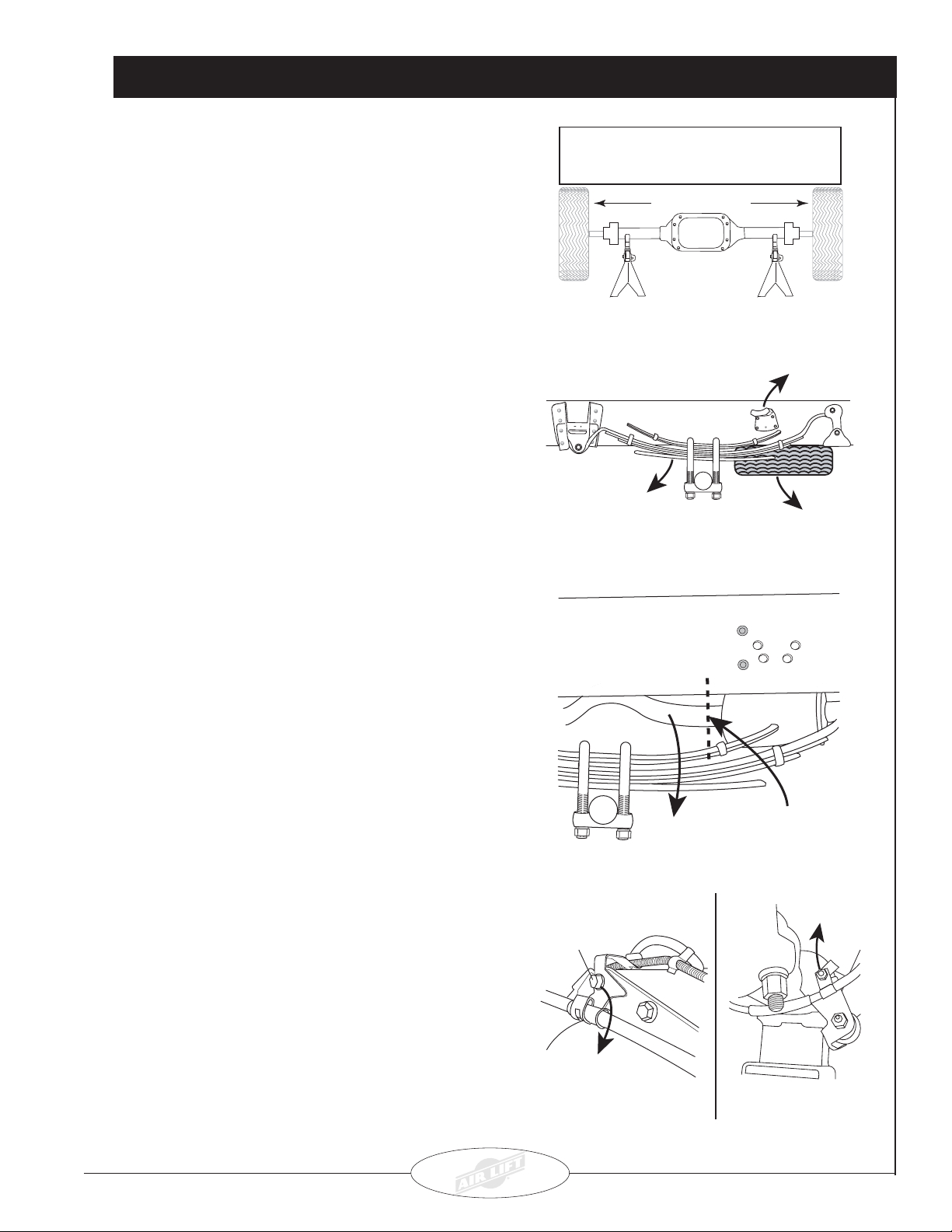
No Load in Truck
Remove Wheel Remove Wheel
IMPORTANT: Measure and record the driveline angles
in the chassis as fi rst received (Figure 21).
1. Elevate the rear of the vehicle and secure the frame
with jack stands or a frame-contact hoist. Support
the axle (Figure 1).
2. Remove the spare tire, both leaf springs, and the
rear frame contact overload brackets, if equipped,
from the frame (Figure 2).
NOTE: It will be necessary to cut the driver side
bolt out of the spring retainer because of how
the gas tank is positioned. A replacement 16
mm bolt is supplied for reinstallation. Retain
the front spring eye bolt from the passenger side
and nuts for later use.
NOTE: It may be necessary to remove the trailer
hitch in order to remove the bolts from the spring
hanger.
NOTE: After removing the factory steel springs,
check the axle spring perches for side-to-side
angle uniformity. Refer to the Inspecting Axle
Spring Perch Uniformity section for information
on installing the supplied 1° wedge shim.
Support the axle with jack
stands and raise or lower
to Normal Ride Height.
Driver-Side View
REMOVE
Leaf Spring.
Driver-Side View
Figure 1
Axle
Figure 2
REMOVE Frame
Contact Overload
Upper Bracket
if equipped.
REMOVE
Spare Tire.
Installing the RoadTamer System
3. Cut off the tailpipe behind the muffl er and remove.
Leave enough room on the muffler to install a
replacement pipe (Figure 3).
4. Remove the bolts securing the brake cables to the
rear end (Figure 4).
Technical Support
1-800-248-0892
Ext. 2
Axle
Top Rear End
Cover Bolt
Remove bolt and
discard bracket.
REMOVE
excess tailpipe.
Figure 3
Figure 4
CUT OFF tailpipe behind
muffler. Leave enough
room to attach a
replacement pipe.
Remove
Bolt
Driver Side
Emergency Brake Cable
4
Inspecting Axle Spring Perch Uniformity
1. After removing the factory steel springs, check
the axle spring perches for side-to-side angle
uniformity. Without disturbing the axle position,
place a magnetic angle protractor on one perch and
note the angle. Next, place the angle protractor on
the other perch and note the angle there as well.
A difference of less than 1° is normal and does
not require a shim. If the difference between the
two angles exceeds 1°, use the supplied 1° wedge
shim to correct the difference.
2. Place the 1° wedge shim on one axle spring perch
and re-measure the angles to verify that they equal
less than 1°. Use the centering pin to attach the
wedge to the correct beam and install the beams
as directed in the section titled Attaching the Axle
Beams. DO NOT TIGHTEN FASTENERS until you
have checked the driveline angles as instructed in
Attaching the Axle Beams
NOTE: For 4WD crew cab models, refer to the
manual provided with the driveshaft spacer kit
# 26029 (purchased seperately) at this time. You
must have this spacer kit before proceeding. If you
do not already have spacer kit # 26029, you can
purchase it by calling Air Lift’s Customer Service
Department at 800-248-0892, extension 1.
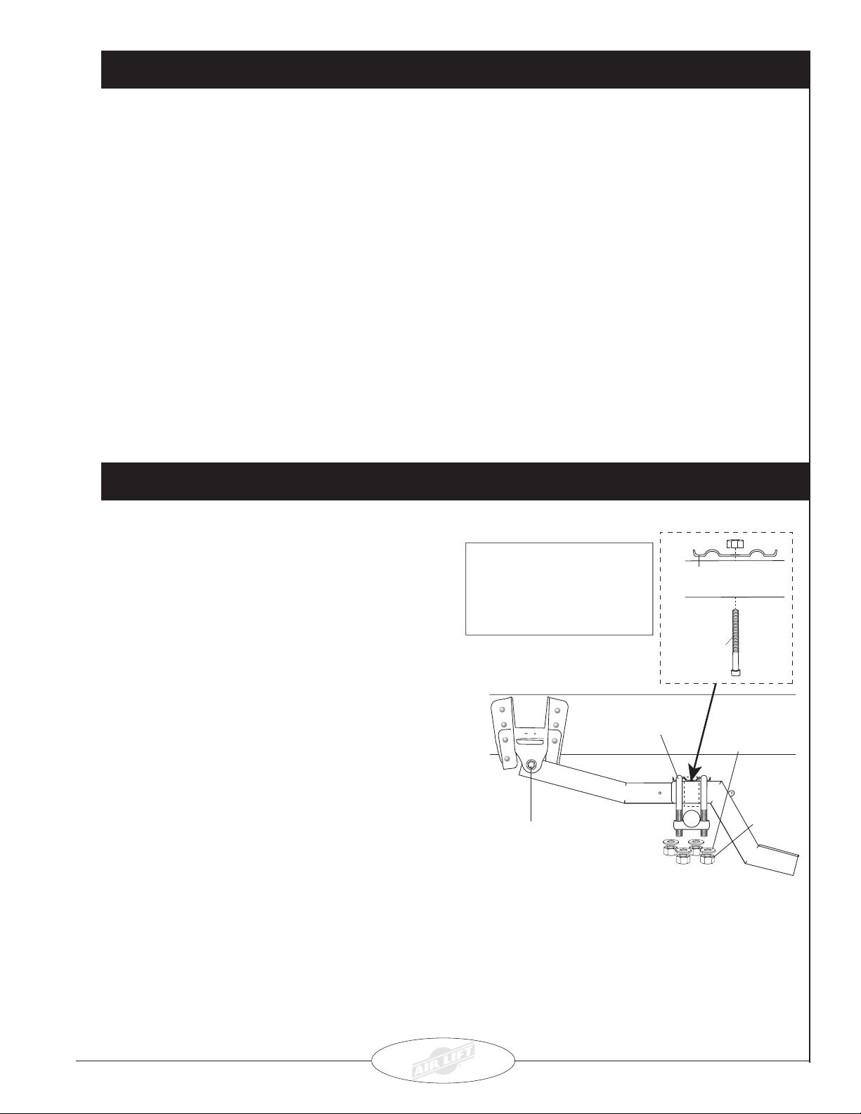
1. Attach the centering pins through each beam with
the round head facing down. Tighten the centering
pin nut securely (Figure 5).
the section dealing with that topic toward the back of
this manual.
NOTE: You must check the driveline angles for
cancellation before completing the installation
(see the Driveline Angles section toward the back
of the manual). It may be necessary to reverse the
shim and place it on the opposite side to maintain
correct driveline angles.
3. Measure from the top of each frame rail (at the rear of
the frame) to the ground. The measurement must be
made at vehicle ride height with the vehicle on level
ground and with equal tire pressures. The vehicle
levelness is acceptable if the two measurements from
side-to-side are within 3/8”. If the vehicle is not level
within 3/8”, check that the 1° shim is placed properly.
For 4WD crew cab models, refer to the manual
provided with the driveshaft spacer kit # 26029
(purchased seperately) at this time. You must
have this spacer kit before proceeding. If you
do not already have spacer kit # 26029, you can
purchase it by calling Air Lift’s Customer Service
Department at 800-248-0892, extension 1.
Driver-Side Shown
Stock Spring
Retainer
Centering
Pin
Beam
Installing the RoadTamer System
2. Attach the driver-side beam assembly to the front
spring eye hanger using the supplied 16 mm bolt
(stock bolt on passenger side) and washer and the
previously removed stock nut (Figure 5). Be sure
to index the centering pin into the spring perch in
order to properly locate the axle and the beam.
Leave loose.
NOTE: The emergency brake cable should go
over the beam assembly.
3. Attach the beam assemblies to the axle with the
hardware shown in Figure 5. Secure snugly, but
do not completely tighten at this time.
NOTE: It will be necessary to use the stock
spring retainer between the u-bolts and the
beams.
NOTE: Draw the nuts down evenly on the
retainer by using a criss-cross tightening
pattern.
Technical Support
1-800-248-0892
Ext. 2
U-bolt
A 16mm bolt and washer
are supplied for the driver
side only. Use the stock
bolt on the passenger side.
Figure 5
Axle
5
/8"
Flat
Washer
5
/8" Nut
5
Attaching the Frame Brackets
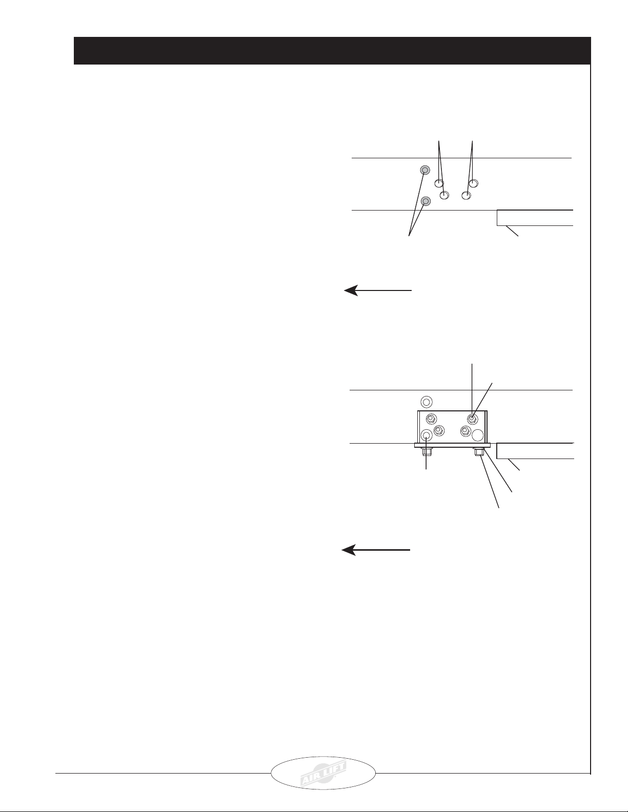
1. Install the driver-side frame bracket. Line up the
lower crossmember rivet with the lower, forward
hole in the upper bracket. Clamp the bottom of the
fl ange on the bracket to the frame fl ange using vise
grips or welding clamps.
2. a) If there are existing holes:
Line up the upper bracket holes with the
existing contact overload bracket holes in the
frame (Figure 6). Attach the bracket to the
frame with four ½” bolts, eight washers and
four nyloc nuts. Leave loose at this time.
b) If there are NO existing holes:
Drill a ½” hole using the upper bracket as a
template. Attach the bracket with one ½”
bolt, two fl at washers and one nyloc nut.
Tighten just until snug. Do not overtighten.
3. Drill two ½” holes through the frame fl ange using the
top hole in the bracket as a template. Attach the
upper bracket using two ½” bolts, four fl at washers
and two nyloc nuts. Tighten just until snug. Do not
overtighten.
Existing Frame Contact
Overload Holes
(If not equipped,
drill out to ½")
Cross Member Rivets
FORWARD
Driver-Side Shown
Figure 6
½" Flat Washer
½" Bolt
Frame
Trailer Hitch
Installing the RoadTamer System
4. Drill the remaining holes through the side, if needed,
using the bracket holes as a template. Attach the
remaining ½” hardware shown in Figure 7, starting
with the bottom ½” bolts. Torque all hardware to 107
ft.lbs.
5. Repeat steps 1-4 for the passenger side.
6. Reinstall the spare tire.
Cross member rivet
must be in forward
hole in upper bracket.
FORWARD
Frame
Trailer Hitch
½" Flat Washer
½" Bolt
Driver-Side Shown
Figure 7
Technical Support
1-800-248-0892
Ext. 2
6
 Loading...