

Page 1

IMPORTANT INSTRUCTIONS -
OPERATING MANUAL
AD Series Range Hood
READ AND SAVE THESE INSTRUCTIONS
READ CAREFULLY BEFORE ATTEMPTING TO ASSEMBLE, INSTALL, OPERATE OR MAINTAIN THE PRODUCT DESCRIBED. PROTECT
YOURSELF AND OTHERS BY OBSERVING ALL SAFETY INFORMATION. FAILURE TO COMPLY WITH
INSTRUCTIONS COULD RESULT IN PERSONAL INJURY AND/OR PROPERTY DAMAGE!
RETAIN INSTRUCTIONS FOR FUTURE REFERENCE.
GENERAL SAFETY INFORMATION
When using electrical appliances, basic precautions
should always be followed to reduce the risk of fire,
electric shock and injury to person, including the following:
WARNING: TO REDUCE THE RISK OF FIRE, ELECTRIC SHOCK
AND INJURY TO PERSON, OBSERVE THE FOLLOWING:
1. Read all instructions before installing or using range hood.
2. Use this unit only in the manner intended by the manufacturer. If
you have questions, contact the manufacturer.
3. Before servicing or cleaning the unit, switch power off at service
panel and lock the service disconnecting means to prevent power
from being switched on accidentally. When the service
disconnecting means cannot be locked, securely fasten a prominent
warning device, such as a tag, to the service panel.
4. Installation work and electrical wiring must be done by qualified
person(s) in accordance with all applicable codes and standards,
including fire-related construction.
5. Sufficient air is needed for proper combustion and exhausting of
gases through the flue (chimney) of fuel burning equipment to
prevent back drafting. Follow the heating equipment manufacturer’s
guideline and safety standards such as those published by the
National Fire Protection Association (NFPA) and the American
Society for Heating, Refrigeration, and Air Conditioning Engineers
(ASHRAE), and the local code authorities.
CAUTION: FOR GENERAL VENTILATING USE ONLY. DO NOT USE
TO EXHAUST HAZARDOUS OR EXPLOSIVE MATERIALS AND VAPORS.
6. When cutting or drilling into wall or ceiling, do not damage electrical
wiring and other hidden utilities.
CAUTION: TO REDUCE THE RISK OF FIRE AND TO PROPERLY
EXHAUST AIR, BE SURE TO DUCT AIR OUTSIDE - DO NOT VENT
EXHAUST AIR INTO SPACES WITHIN WALLS OR CEILINGS OR INTO
ATTICS, CRAWL SPACES, OR GARAGES.
7. This unit must be grounded.
8. To avoid motor bearing damage and noisy and/or unbalanced
impellers, keep drywall spray, construction dust, etc. off power unit.
WARNING: TO REDUCE THE RISK OF FIRE, ELECTRIC SHOCK, DO
NOT USE THIS FAN WITH ANY SOLID-STATE SPEED CONTROL DEVICE.
WARNING: TO REDUCE THE RISK OF A RANGE TOP GREASE FIRE:
a) Never leave surface units unattended at high settings. Boilovers
cause smoking and greasy spillovers that may ignite. Heat oils
slowly on low or medium settings.
b) Always turn hood ON when cooking at high heat or when
flambéing food (ie. Crepes Suzette, Cherries Jubilee, Peppercorn
Beef Flambé).
c) Clean ventilating fans frequently. Grease should not be allowed
to accumulate on fan filter.
d) Use proper pan size. Always use cookware appropriate for the
size of the surface element.
WARNING: TO REDUCE THE RISK OF INJURY TO PERSONS IN
THE EVENT OF A RANGE TOP GREASE FIRE, OBSERVE THE FOLLOWING:
a) SMOTHER FLAMES with a close-fitting lid, cookie sheet, or
metal tray, then turn off burner. BE CAREFUL TO PREVENT
BURNS. If the flames do not go out immediately, EVACUATE
AND CALL THE FIRE DEPARTMENT.
b) NEVER PICK UP A FLAMING PAN - You may be burned.
c) DO NOT USE WATER, including wet dishcloths or towels - a
violent steam explosion will result.
d) Use an extinguisher ONLY if:
I. You know you have a Class ABC extinguisher, and you already
know how to operate it.
II. The fire is small and contained in the area where it started.
III. The fire department is being called.
IV. You can fight the fire with your back to an exit.
WARNING: TO REDUCE THE RISK OF FIRE, USE ONLY METAL
DUCTWORK.
6728001 Rev. B 3-07
SAVE THESE INSTRUCTIONS
www.airkinglimited.com
1
Page 2
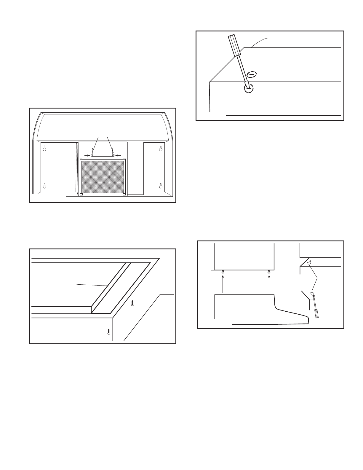
INSTALLATION INSTRUCTIONS
1. Unpack hood from the carton and confirm that all pieces are present.
In addition to the range hood you should have:
1 - Aluminum Grease/Charcoal Filter
4 - #8 Mounting Screws
1 - Wire Compartment Cover and Screw
1 - Instruction/Safety Sheet
2. Lay the hood flat on a table so the underside is facing you. Use a
piece of cardboard to avoid damaging the table or the hood.
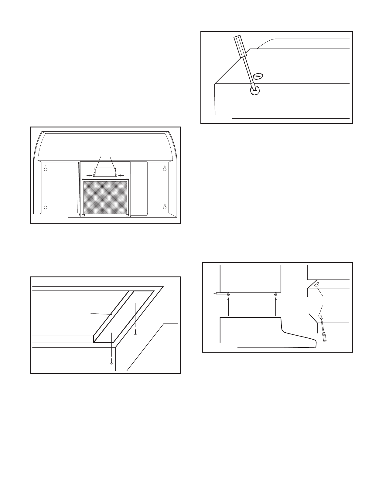
3. Remove lamp cover by squeezing the two tabs together (Figure 1).
Figure 3
Tabs
Figure 1
4. Install a 60 watt maximum type A19 bulb and reinstall the lamp cover.
Prepare the location for Hood Support
1. If the hood will be installed under cabinets that have a recessed
bottom, it will be necessary to install wood mounting strips (not
included) so the hood will mount properly (Figure 2).
Wood Strip
CAUTION: MAKE SURE POWER IS SWITCHED OFF AT SERVICE
PANEL BEFORE STARTING INSTALLATION.
Installing the Range Hood
1. Once the proper knockout(s) have been removed, either hold the
hood up to the installation location and mark the locations of the
ducting (if applicable), electrical, and mounting holes or mark the
locations by measurement.
2. Cut appropriate holes for ducting connection (if applicable) and
electrical connection in the wall/cabinet.
3. Install an approved wire connector to the electrical knockout of
the hood and guide the electrical cable through the hood, allowing
at least 6" of wire for connections and tighten.
4. Install the 4 mounting screw at the previously marked locations.
Leave approximately 1/8" clearance. Slide the hood in place through
the keyhole slots and align the front of the hood so that it is flush with
the front of the cabinets. Tighten all screws securely (Figure 4).
1/8"
Keyhole
Figure 2
2. The thickness of the strips should be the same as the recess of the
cabinet and they should be approximately 2" wide.
3. Install the strips using appropriate length wood screws (not included).
Make sure the strips line up to the keyhole slots of the range hood.
Prepare the Hood for Installation
1. Determine where the electrical service will enter the hood and
remove the appropriate electrical knockout by inserting a screw
driver into the slot and rocking back and forth until the knockout
comes loose (Figure 3).
6728001 Rev. B 3-07
www.airkinglimited.com
Figure 4
Wiring
CAUTION:
IN ACCORDANCE WITH LOCAL CODES, ORDINANCES, OR NATIONAL
ELECTRICAL CODE. IF YOU ARE UNFAMILIAR WITH METHODS OF
INSTALLING ELECTRICAL WIRING, SECURE THE SERVICES OF A
QUALIFIED ELECTRICIAN.
1. Connect the 2 loose White wires from the range hood to the White
wire from the supply, and the loose Black wire from the range hood
to the Black wire of the supply. Connect the ground wire (green or
bare) from the supply to the green ground screw of the hood. Use
approved methods for all connections (Figure 5).
ALL ELECTRICAL CONNECTIONS MUST BE MADE
2
Page 3
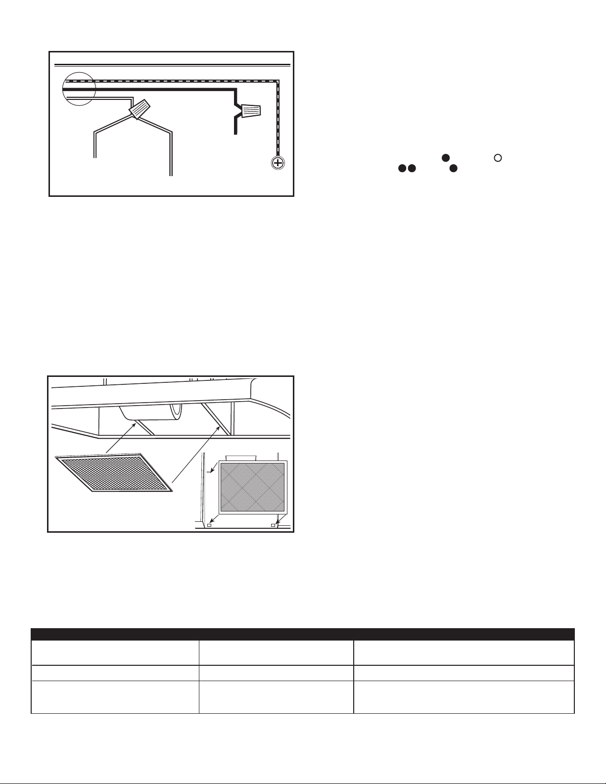
Hot (Black)
White from Lamp
Figure 5
NOTE: DO NOT disconnect any wiring that has already been crimped
with a wire connector from the factory.
2. Install the wire compartment cover and tighten screw. Make sure
all wiring is securely contained within the wire compartment.
White from Motor
Ground
Ducting (if applicable)
CAUTION: ALL DUCTING MUST COMPLY WITH LOCAL AND
NATIONAL BUILDING CODES.
1. Your range hood comes ready for ductless operation, and no
additional ducting is required.
Finishing the Installation
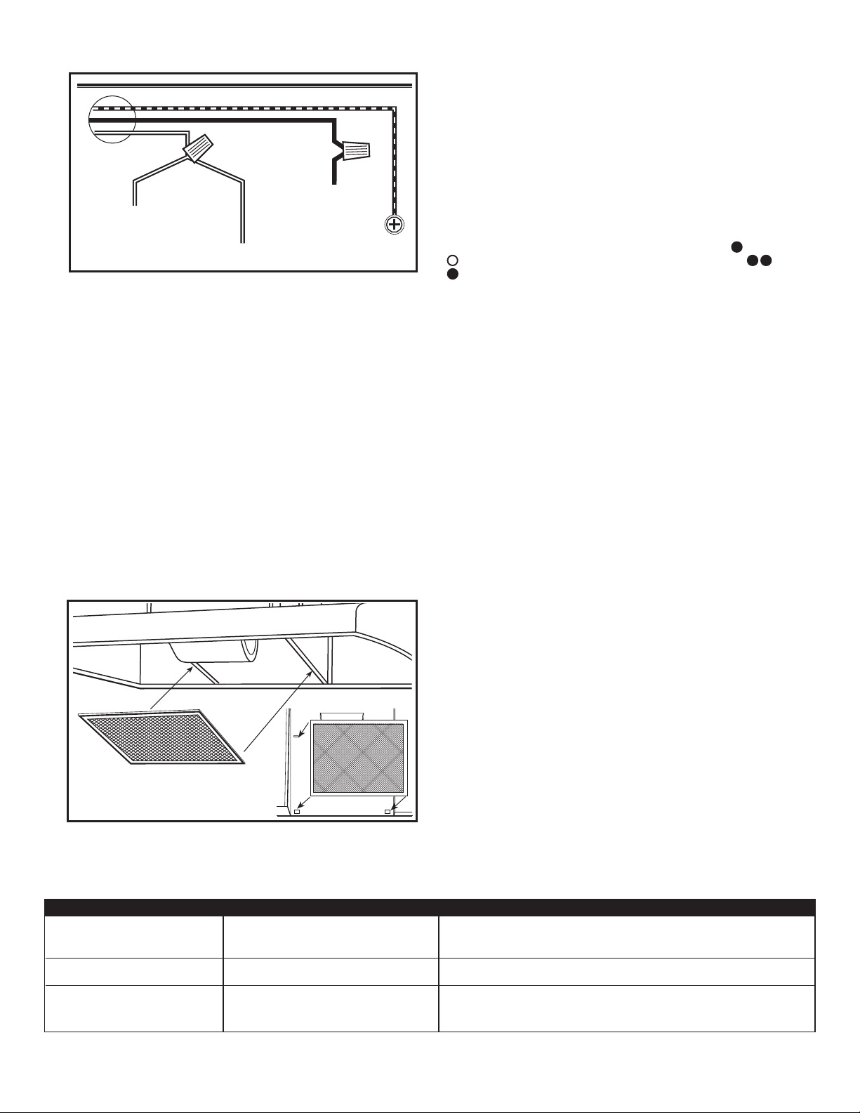
1. Install the appropriate filter sliding the back side of the filter into
the tab and pressing the front of the filter into place (Figure 6).
2. Turn switches to the “OFF” position and restore power. Test that
the light and the fan are operating properly.
3. If there is any vibration noise, check for the source and try to
tighten fasteners.
Operation
Controls
Your Range Hood is equipped with two rocker style switches with one
controlling the lighting and the other controlling the exhaust fan. The
light switch has two positions, ON (
position switch, HIGH (
position of the switch.
), LOW ( ), and OFF. OFF is the middle
) and OFF ( ). The fan is a three
Maintenance
CAUTION:
PANEL BEFORE SERVICING THE UNIT.
Filters
Grease/Charcoal Filter - Your range hood is equipped with a combination
grease/charcoal filter. This filter cannot be washed and must be discarded
and replaced when it has become noticeably dirty, has stopped filtering
the odors, or at least once per year. Replace with Air King Model RF55
Combination Odor/Grease Filter.
Cleaning
MAKE SURE POWER IS SWITCHED OFF AT SERVICE
CAUTION: DO NOT USE GASOLINE, BENZINE, THINNER, HARSH
CLEANSERS, ETC., AS THEY MAY DAMAGE THE RANGE HOOD.
1. Clean your range hood with a mild detergent, such as dishwashing
liquid, and dry with a soft cloth. NEVER USE ANY ABRASIVE PADS
OR SCOURING POWDERS. Completely dry before restoring power.
NEVER IMMERSE ELECTRICAL PARTS IN WATER.
2. The fan assembly can be vacuumed when build up (dirt, lint, etc.)
accumulates over time. The fan is permanently lubricated and does
not require oiling.
Figure 6
Troubleshooting Guide
Trouble Probable Cause Suggested Remedy
1. Hood does not operate when the switch is on. 1a. A fuse may be blown or a circuit tripped. 1a. Replace fuse or reset circuit breaker.
1b. Wiring is not connected properly. 1b. Turn off power to unit. Check that all wires are connected
2. Hood is operating, but air moves slower than normal. 2. Filter needs replacing. 2. Check filter for build up and replace if necessary.
3. Hood is making a rattling noise. 3a. Motor is loose. 3a. Turn off power to unit. Remove filter, check that all screws are
3b. Filter is loose. 3b. Turn off power to unit. Check that filter is tight.
6728001 Rev. B 3-07
www.airkinglimited.com
fully tightened.
3
Page 4

LIMITED WARRANTY
All products manufactured by Air King Limited are warranted for one year from the date of purchase against defects in workmanship
and/or material. In addition, all ventilating/exhaust fans, heaters, combination fan lights and/or heaters, and range hoods are
guaranteed for five years from the date of purchase against defects in workmanship and/or material.
This warranty does not cover any labor or shipping costs or the cost of replacement components as part of routine maintenance
such as: range hood grease filters, charcoal filters or combination charcoal/grease filters; replacement light bulbs in range hoods
or bathroom fan/light/bulb heater combinations. As well, any damage or failure caused by abuse, misuse, abnormal usage, faulty
installation, or improper maintenance will not be covered by this warranty.
In order to make a claim on this warranty, you must be the original consumer of the product. You will be required to present to
Air King the original bill of sale showing: date of purchase, place of purchase and model purchased. Failure to meet these
requirements will void your warranty.
Air King will not be held responsible for any bodily injury or damages to personal property or real estate whether caused directly
or indirectly by the product. Some states and provinces do not allow the exclusion or limitation of incidental or consequential
damages and some states do not allow limitations on how long an implied warranty lasts, so these exclusions or limitations may
not apply to you. This warranty gives you specific legal rights and you may have other rights which vary from state to state and
province to province.
FOR PARTS OR TECHNICAL ASSISTANCE
Please call: 1-800-465-7300, MONDAY THROUGH FRIDAY, BETWEEN THE HOURS OF 8 AM AND 4:00 PM EST.
PLEASE DO NOT RETURN PRODUCT TO PLACE OF PURCHASE.
Reference the type and style of product (located on label inside of the product) when you call.
For more information please visit our website: wwwairkinglimited.com
6728001 Rev. B 3-07
www.airkinglimited.com
4
Page 5
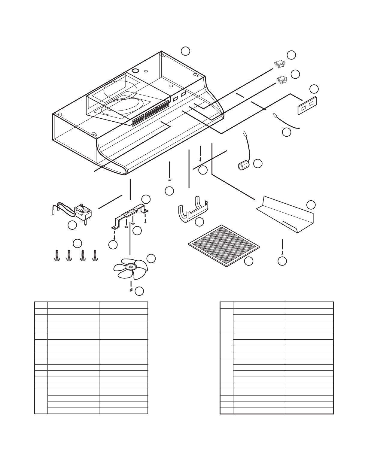
REPLACEMENT PARTS DIAGRAM
18
17
16
15
14
13
10
12
11
6
9
7
5
19
# Description Replacement Part #
1 Filter RF55 5S4108001
2 Push Nut 5S4199001
3 Fan Blade 5S4199002
4 #8 B Screw 5S1999015
5 Hex Nut 5S1999006
6 Motor Bracket 5S4199003
7 Light Lens 5S4199004
8 #6 AB Screw 5S1999004
9 Wire Compartment Cover 5S4199005
10 Lamp Holder 5S4199006
11 Bushing 5S1999016
12 #10 Ground Screw 5S1999002
13 Jumper Wire 5S4199007
14 Switch Plate - White 5S1421003
Biscuit 5S1421004
Almond 5S1421005
Black 5S1421006
4
3
81
2
# Description Replacement Part #
15 Motor Switch - White 5S1418003
Biscuit 5S1418004
Almond 5S1418005
Black 5S1418006
16 Light Switch - White 5S1419003
Biscuit 5S1419004
Almond 5S1419005
Black 5S1419006
17 Wrapper -21" 5S1425010
24" 5S1425020
30" 5S1425030
36" 5S1425040
18 Motor 5S2199001
19 #8 Screw 5S1999017
Installer: _________________________________________________________ Installation Date:_________________________________________
Place of Purchase: _________________________________________________ Model Number: __________________________________________
6728001 Rev. B 3-07
www.airkinglimited.com
5
Page 6

INSTRUCTIONS IMPORTANTES –
MANUEL D’OPÉRATION
Séries AD
Hotte de Cuisine
LIRE ET CONSERVER CES INSTRUCTIONS
LIRE SOIGNEUSEMENT AVANT DE TENTER D’ASSEMBLER, INSTALLER, OPÉRER OU DE RÉPARER LE PRODUIT DÉCRIT. PROTÉGEZ
VOUS-MÊME ET LES AUTRES EN OBSERVANT TOUTE L’INFORMATION DE SÉCURITÉ. FAILLIR À SE CONFORMER AUX
INSTRUCTIONS PEUT RÉSULTER EN BLESSURE PERSONNELLE GRAVE ET/OU EN DOMMAGE À LA PROPRIÉTÉ.
CONSERVER CES INSTRUCTIONS POUR RÉFÉRENCES FUTURES.
INSTRUCTIONS GÉNÉRALES DE SÉCURITÉ
Lors de l’utilisation d’appareils électriques, des précautions de base doivent
toujours être suivies pour réduire les risques d’incendie, de choc
électrique et de blessures corporelles, incluant ce qui suit:
AVERTISSEMENT: POUR RÉDUIRE LES RISQUES D’INCENDIE,
DE CHOC ÉLECTRIQUE OU DE BLESSURES PERSONNELLES OBSERVER
CE QUI SUIT:
1. Lire toutes les instructions avant d’installer ou d’utiliser la hotte de cuisine.
2. Utiliser cette unité seulement de la manière pour laquelle le fabricant
l’a conçu. Si vous aviez des questions, veuillez contacter le fabricant.
3. Avant d’effectuer un service ou de nettoyer l’unité, couper
l’alimentation électrique dans le panneau de distribution et verrouiller
le dispositif de déconnexion afin d’éviter que l’alimentation ne
revienne accidentellement. Lorsque le dispositif ne peut être
verrouillé, fixer solidement un avis d’avertissement, tel qu’une
étiquette, au panneau de distribution.
4. Le travail d’installation et le câblage électrique doivent être
effectués par une(des) personne(s) qualifiée(s) en conformité avec
tous les codes et normes applicables, incluant la construction
relative aux incendies.
5. De l’air en quantité suffisante est requis pour la bonne combustion
et l’évacuation de gaz par le conduit (cheminée) provenant
d’équipement de brûlage au combustible pour prévenir un
refoulement. Suivre les directives du fabricant de l’équipement de
chauffage et les normes de sécurité telles que celles publiées par
la National Fire Protection Association (NFPA) et de la American
Society for Heating, Refrigeration, and Air Conditioning Engineers
(ASHRAE), et de celles des autorités locales du code.
AVERTISSEMENT: POUR USAGE DE VENTILATION GÉNÉRALE
EXCLUSIVEMENT. NE PAS UTILISER POUR ÉVACUER DU MATÉRIEL ET
DES VAPEURS DANGEREUSES OU EXPLOSIVES.
6. Lors de coupe ou de perçage des murs et plafonds, ne pas
endommager le filage électrique et autres utilités cachées.
AVERTISSEMENT: POUR RÉDUIRE LES RISQUES D’INCENDIE
ET POUR ÉVACUER L’AIR ADÉQUATEMENT, ASSUREZ-VOUS D’ÉVACUER
L’AIR VERS L’EXTÉRIEUR – NE PAS ÉVACUER L’AIR DANS DES ESPACES
DANS LES MURS, LES PLAFONDS OU LES GRENIERS, LES GALERIES
TECHNIQUES OU LES GARAGES.
7. Cette unité doit être mise à la terre.
8. Pour éviter des dommages aux roulements des moteurs et/ou des
hélices bruyantes ou déséquilibrées, empêcher la poussière de cloison
sèche, poussière de construction, etc., d’atteindre l’unité de puissance.
AVERTISSEMENT: POUR RÉDUIRE LES RISQUES D’INCENDIE
OU DE CHOC ÉLECTRIQUE, NE PAS UTILISER CE VENTILATEUR AVEC
UN RÉGULATEUR DE VITESSE ÉLECTRONIQUE.
AVERTISSEMENT: POUR RÉDUIRE LES RISQUES D’INCENDIE
DE GRAISSE SUR LE DESSUS DE LA CUISINIÈRE:
a) Ne jamais laisser les unités de surface à des degrés élevés sans
surveillance. Les débordements par bouillonnement produisent de
la fumée et des débordements graisseux qui peuvent s’enflammer.
Chauffer les huiles lentement à des degrés faibles ou modérés.
b) Toujours mettre la hotte EN MARCHE lors de cuisson à haute
température ou lors de flambage de nourriture (par ex., des
Crêpes Suzette, de Cerises Jubilées, steak flambé, etc.)
c) Nettoyer les ventilateurs d’évacuation fréquemment. Aucune
accumulation de graisse ne devrait être tolérée sur les filtres
du ventilateur.
d) Utiliser des poêlons de taille appropriée. Toujours utiliser les batteries
de cuisine appropriées pour la taille de l’élément de surface.
AVERTISSEMENT: POUR RÉDUIRE LES RISQUES DE BLESSURES
PERSONNELLES DANS L’ÉVENTUALITÉ D’UN FEU DE GRAISSE SUR LA
SURFACE DE CUISSON, SUIVRE LES INDICATIONS SUIVANTES:
a) ÉTOUFFER LES FLAMMES avec un couvercle bien ajusté, une
tôle à biscuits, ou un cabaret de métal, puis, mettre le gril hors
fonction. PRENEZ SOIN D’ÉVITER LES BRÛLURES. Si les flammes
ne s’éteignent pas immédiatement, ÉVACUER ET APPELER LE
SERVICE DES INCENDIES.
b) NE JAMAIS SAISIR UN POÊLON EN FLAMME – vous pourriez
être brûlé.
c) NE PAS UTILISER DE L’EAU, incluant les linges à vaisselle ou
les serviettes mouillées – il en résulterait une violente explosion
de vapeur.
d) Utiliser un extincteur SEULEMENT SI:
I. Vous savez que vous avez un extincteur de classe ABC, et
que vous savez déjà comment l’opérer.
II. Le feu est petit et contenu dans la zone où il a commencé.
III. On appelle le service des incendies.
IV. Vous pouvez combattre l’incendie avec une sortie derrière vous.
AVERTISSEMENT: POUR RÉDUIRE LES RISQUES D’INCENDIE,
UTILISER UNIQUEMENT DES CONDUITS EN MÉTAL.
6728001 Rev. B 3-07
CONSERVER CES INSTRUCTIONS
www.airkinglimited.com
6
Page 7
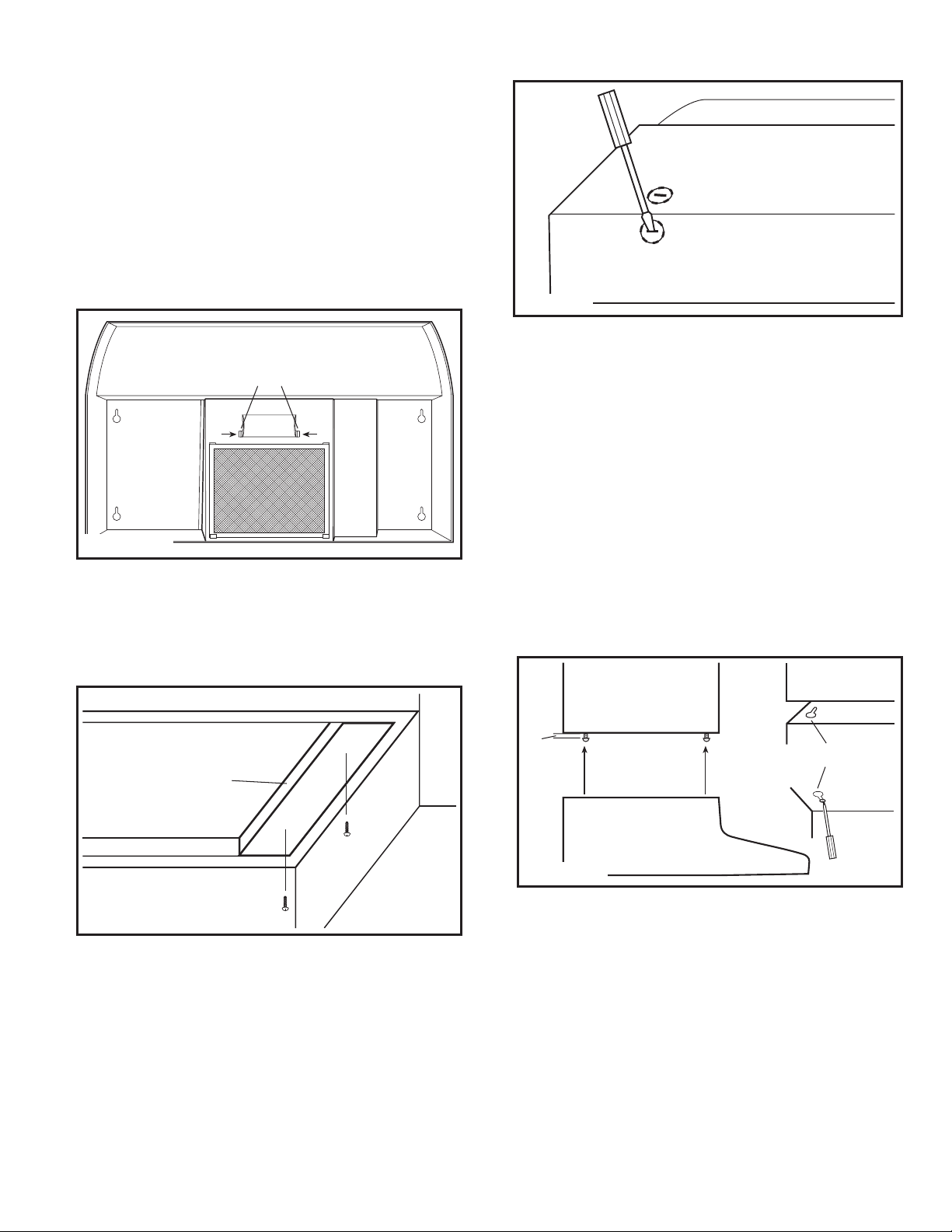
INSTRUCTIONS D’INSTALLATION
1. Déballer la hotte de sa boîte et confirmer que toutes les pièces
sont présentes. En plus de la hotte de cuisine vous devriez avoir:
1 - Filtre combiné graisse en aluminium/charbon
4 - Vis de montage #8
1 - Couvercle du compartiment de câblage et vis
1 - Feuille d’instructions/ sécurité
2. Déposer la hotte sur une table plane de manière à ce que le dessous
soit face à vous. Utiliser une pièce de carton pour éviter
d’endommager la table ou la hotte.
3. Enlever le couvercle de lampe en pressant les deux onglets
ensemble (Figure 1).
Attaches
Figure 1
4. Installer une ampoule de type A19 d’un maximum de 60 watts et
réinstaller le couvercle de lampe.
Préparer l’emplacement pour le Support de la Hotte
1. Si la hotte sera installée sous des armoires qui ont un fond en retrait,
il sera nécessaire d’installer des languettes de montage en bois (non
incluses) pour que la hotte s’installe correctement (Figure 2).
Figure 3
AVERTISSEMENT: VOUS ASSURER QUE L’ALIMENTATION
EST COUPÉE AU PANNEAU DE SERVICE AVANT DE COMMENCER
L’INSTALLATION.
Installation de la Hotte de Cuisine
1. Une fois que la (les) bonne(s) alvéole(s) a(ont) été enlevée(s), au choix,
tenir la hotte à l’emplacement d’installation et marquer les endroits
appropriés des trous pour les conduits (si applicable), l’électricité et
de montage ou encore, marquer les emplacements en les mesurant.
2. Couper les trous appropriés pour le raccordement des conduits (si
applicable) et électrique dans le mur/ l’armoire.
3. Installer un connecteur de filage approuvé à l’alvéole pour l’électricité
de la hotte et guider les câbles électriques au travers de la hotte, en
laissant au moins 15,24 cm (6 po) de fil pour le raccordement puis serrer.
4. Installer les 4 vis de montage aux endroits marqués précédemment.
Laisser un dégagement d’environ 0,33 cm (1/8 po). Glisser la hotte
en place au travers des trous en poire et aligner le devant de la hotte
pour qu’il soit à effleurement avec le devant des armoires. Visser
fermement toutes les vis (Figure 4).
Languette en bois
Figure 2
2. L’épaisseur des languettes devrait être la même que le retrait de
l’armoire et elles devraient être d’une largeur de 5 cm (2 po).
3. Installer les languettes avec des vis à bois de longueur appropriées
(non incluses). Assurez-vous que les languettes sont alignées avec
les trous en poire de la hotte.
Préparer la Hotte pour son Installation
1. Déterminer où le service électrique entrera dans la hotte et enlever
les alvéoles défonçables électriques appropriées en insérant un
tournevis dans la fente et en en le repliant vers l’avant et l’arrière
jusqu’à ce que les alvéoles deviennent lâches (Figure 3).
6728001 Rev. B 3-07
www.airkinglimited.com
0,33 cm
(1/8 po)
Trou en clef
Figure 4
Câblage
AVERTISSEMENT:
ÊTRE FAITES EN CONFORMITÉ AVEC LES CODES ÉLECTRIQUES LOCAUX
OU NATIONAUX. SI VOUS N’ÊTES PAS FAMILIER AVEC LES MÉTHODES
D’INSTALLATION DE CÂBLAGE ÉLECTRIQUE, RECOURREZ AUX SERVICES
D’UN ÉLECTRICIEN QUALIFIÉ.
1. Connecter les deux fils lâches Blancs de la hotte de cuisine au fil Blanc
de l’alimentation, et le fil lâche Noir de la hotte au fil Noir de l’alimentation.
Connecter le fil de mise à la terre (vert ou dénudé) de l’alimentation
à la vis verte de mise à la terre de la hotte. Utiliser des méthodes de
connexion approuvées pour toutes les connexions (Figure 5).
TOUTES LES CONNEXIONS DOIVENT
7
Page 8
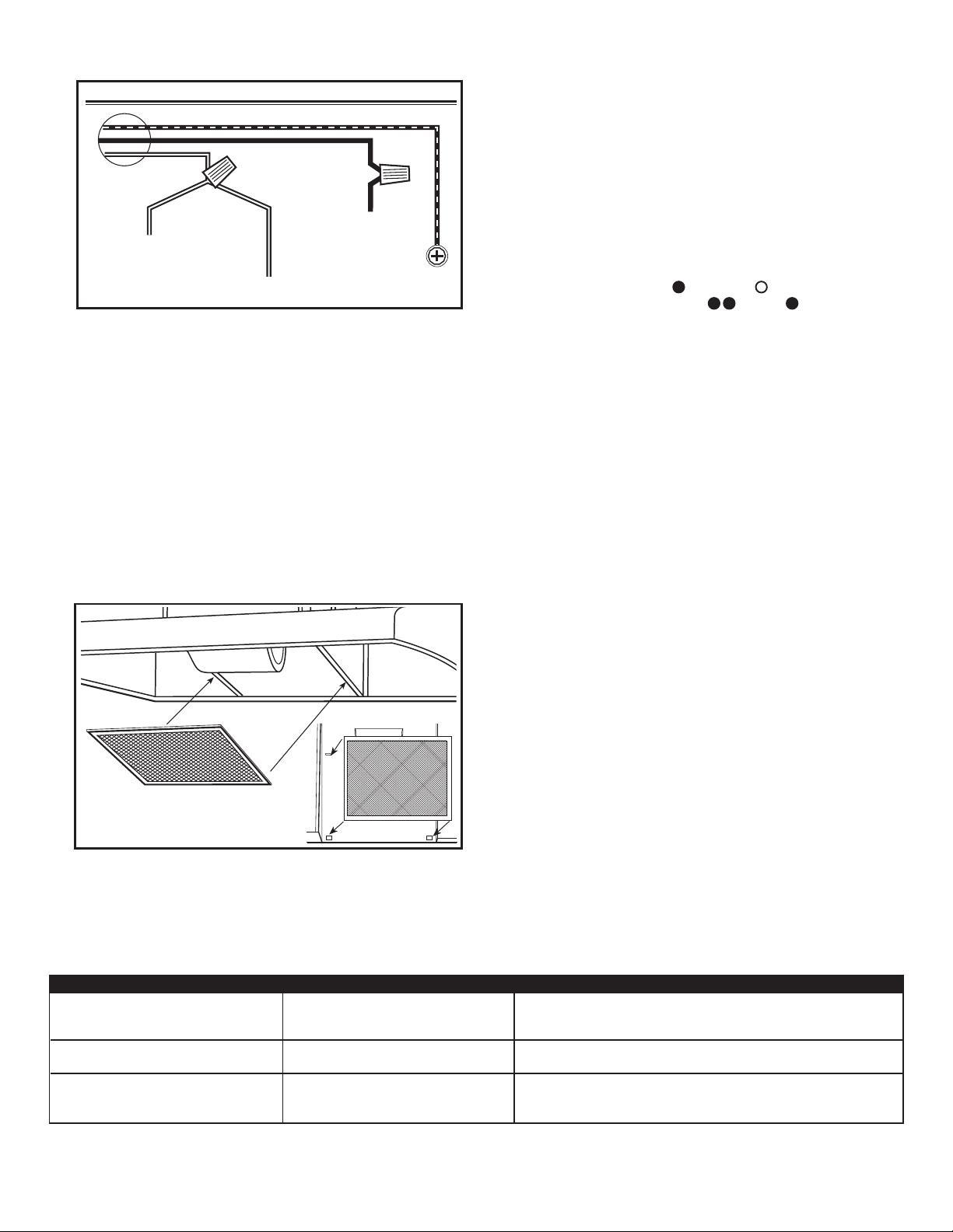
Fil chaud (Noir)
Fil blanc de
douille lègére
Figure 5
REMARQUE : NE PAS déconnecter quelque fil qui ait déjà été serti avec
un connecteur de fil à l’usine.
2. Installer le couvercle du compartiment de câblage et serrer la vis.
Assurez-vous que tout le câblage est fermement contenu dans le
compartiment à câblage.
Fil blanc de moteur
Fil de
masse
Conduits (si applicable)
AVERTISSEMENT: TOUS LES CONDUITS DOIVENT ÊTRE
CONFORMES AUX CODES DU BÂTIMENT LOCAUX ET NATIONAUX.
1. Votre hotte de cuisine est livrée prête pour opération sans conduit,
et aucun conduit additionnel n’est requis.
Finition de l’installation
1. Installer le filtre approprié, en glissant le côté arrière du filtre dans
l’onglet et en pressant l’avant du filtre en place (Figure 6).
2. Mettre les interrupteurs en position « HORS (OFF) » et rétablir
l’alimentation. Tester que la lampe et le ventilateur fonctionnent
correctement.
3. S’il y a un bruit de vibration, recherchez-en la source et essayez
de serrer les attaches ou d’ajuster le ruban pour canalisations pour
faire un raccord ou un scellant plus serré.
Opération
Contrôles
Votre Hotte de Cuisine est équipée de deux interrupteurs à type basculant
dont l’un contrôle l’éclairage et l’autre le ventilateur. L’interrupteur de
la lampe a deux positions, EN (
interrupteur à trois positions, HAUT (
est la position médiane de l’interrupteur.
) et HORS ( ). Le ventilateur a un
), BAS ( ) et HORS. HORS
Entretien
AVERTISSEMENT:
EST COUPÉE AU PANNEAU DE SERVICE AVANT DE FAIRE L’ENTRETIEN
SUR L’UNITÉ.
Filtres
Filtre combiné graisse/ charbon – votre hotte de cuisine est équipée d’un
filtre combiné graisse/ charbon. Ce filtre ne peut pas être lavé et il doit
être jeté et remplacé lorsqu’il sera devenu sale de façon notable, qu’il ait
cessé de filtrer les odeurs, ou au moins une fois par année. Le remplacer
avec un filtre combiné graisse/ odeur Modèle RF55 de Air King.
Nettoyage
VOUS ASSURER QUE L’ALIMENTATION
AVERTISSEMENT: NE PAS UTILISER D’ESSENCE, BENZÈNE,
DILUANT, DE NETTOYANT FORT, ETC., PUISQU’ILS POURRAIENT
ENDOMMAGER LA HOTTE DE CUISINE.
1. Nettoyer votre hotte de cuisine avec un détergent doux, tel que du
liquide à vaisselle, et le sécher avec un chiffon doux. NE JAMAIS
UTILISER DE TAMPON ABRASIF OU DE POUDRE À RÉCURER.
Sécher complètement avant de remettre l’alimentation. NE JAMAIS
IMMERGER LES PARTIES ÉLECTRIQUES DANS L’EAU.
2. Vous pouvez utiliser un aspirateur pour nettoyer l’assemblage du
ventilateur si une accumulation (saletés, mousse, etc.,) s’est produite
avec le temps. Le ventilateur est lubrifié de manière permanente
et ne requiert pas d’huilage.
Figure 6
Guide de dépannage
Trouble Cause possible Solution suggérée
1. La hotte ne fonctionne pas lorsque l’interrupteur 1a. Un fusible peut être grillé ou un disjoncteur peut 1a. Remplacer le fusible ou réinitialiser le disjoncteur.
est à EN (ON). être déclenché.
1b. Le câblage n’est pas raccordé correctement. 1b. Couper l’alimentation de l’unité. Vérifier que tous les fils sont raccordés.
2. La hotte fonctionne, mais l’air circule plus 2. Le filtre a besoin d’être remplacé. 2. Vérifier le filtre pour une accumulation et le remplacer si nécessaire.
lentement que la normale.
3. La hotte produit un son de crécelle. 3a. Le moteur est lâche. 3a. Couper l’alimentation de l’unité. Retirer le filtre, vérifier que toutes les
3b. Le filtre est lâche. 3b. Couper l’alimentation de l’unité. Vérifier que le filtre est bien serré.
vis sont serrées complètement.
6728001 Rev. B 3-07
www.airkinglimited.com
8
Page 9

GARANTIE LIMITÉE
Tous les produits fabriqués par Air King Limited sont garantis pour un an à partir de la date d’achat contre les défauts de main
d’œuvre et/ou de matériel. De plus, tous les ventilateurs / évacuateurs, chaufferettes, combinés ventilateur/ lumière et/ou les
chaufferettes et les hottes de cuisine sont garantis pour cinq années à partir de la date d’achat contre les défauts de main d’œuvre
et/ou de matériel.
Cette garantie ne couvre pas de coûts de transport ou de main d’œuvre ou le coût de remplacement de composantes faisant
partie d’entretien de routine tels que : Filtres à graisse des hottes de cuisine, filtres au charbon ou combiné filtre à graisse/
charbon ; ampoules électriques de remplacement dans les hottes de cuisine ou les combinés ventilateur/ lumière/ chaufferette
pour salle de bain. Aussi, tout dommage ou défaillance causé par un abus, une mauvaise utilisation, une installation fautive ou
un entretien incorrect ne sera pas couvert par cette garantie.
De manière à effectuer une réclamation sous cette garantie, vous devez être l’acheteur original du produit. Il vous sera exigé
de présenter la facture d’achat originale à Air King, qui démontrera : La date d’achat, l’endroit de l’achat et le modèle acheté.
Le manquement à rencontrer ces exigences annulera votre garantie.
Air King ne sera pas tenu responsable de quelque blessure corporelle ou dommage à la propriété ou à l’immeuble que ce soit
causé directement ou indirectement par le produit. Certains États ne permettent pas de limitation sur la durée de la garantie
implicite, ou l’exclusion ou la limitation de dommages indirects ou accessoires, ainsi, ces limitations et exclusions peuvent ne
pas s’appliquer à vous. Cette garantie vous donne des droits légaux spécifiques et vous pouvez aussi avoir des droits qui varient
d’un État à l’autre et d’une province à l’autre.
POUR DES PIÈCES OU DE L’ASSISTANCE TECHNIQUE
Veuillez appeler au 1-800-465-7300, DU LUNDI AU VENDREDI ENTRE 8:00 HRE ET 16:00 HRE HNE.
VEUILLEZ NE PAS RETOURNER CE PRODUIT À L’ENDROIT DE L’ACHAT D’ORIGINE.
Référencer le type et le style du produit (localisé sur l’étiquette à l’intérieur du produit) lorsque vous appelez.
Pour plus d’information, veuillez visiter le site Web de Air King au www.airkinglimited.com
6728001 Rev. B 3-07
www.airkinglimited.com
9
Page 10
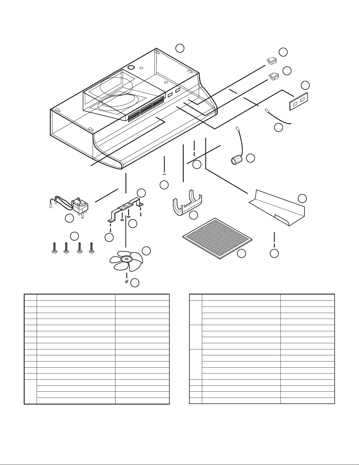
DIAGRAMME DES PIÈCES DE REMPLACEMENT
18
17
16
15
14
13
10
12
11
6
9
7
5
19
4
3
2
# Description # de pièce de remplacement
1 Filtre RF55 5S4108001
Écrou 5S4199001
2
Hélice de ventilateur 5S4199002
3
Vis #8 B 5S1999015
4
5
Écrou hexagonal 5S1999006
Support de moteur 5S4199003
6
7
Lentille de lumière 5S4199004
Vis #6 AB 5S1999004
8
Couvercle de compartiment à câblage 5S4199005
9
Support à lampe 5S4199006
10
Bague 5S1999016
11
12
Vis #10 de mise à la terre 5S1999002
Cavalier 5S4199007
13
Plaque d’interrupteur - Blanc 5S1421003
14
Biscuit 5S1421004
Amande 5S1421005
Noir 5S1421006
81
# Description # de pièce de remplacement
15 Interrupteur du moteur - Blanc 5S1418003
Biscuit 5S1418004
Amande 5S1418005
Noir 5S1418006
16
Interrupteur de lumière - Blanc 5S1419003
Biscuit 5S1419004
Amande 5S1419005
Noir 5S1419006
Bande de recouvrement -53,34 cm (21 po) 5S1425010
17
60,96 cm (24 po) 5S1425020
76,20 cm (30 po) 5S1425030
91,44 cm (36 po) 5S1425040
106,68 cm (42 po) 5S1425050
Moteur 5S2199001
18
Vis #8 5S1999017
19
Installateur: ______________________________________________________ Date d’installation: _______________________________________
Endroit de l’achat: _________________________________________________ Numéro de modèle:_______________________________________
6728001 Rev. B 3-07
www.airkinglimited.com
10
Page 11

INSTRUCCIONES IMPORTANTES –
MANUAL DE OPERACIÓN
Serie AD
Extracción
LEA Y GUARDE ESTAS INSTRUCCIONES
LEA CUIDADOSAMENTE ANTES DE INTENTAR MONTAR, INSTALAR, OPERAR O MANTENER EL PRODUCTO DESCRITO. PROTÉJASE
Campana de
A USTED MISMO Y A LOS DEMÁS OBEDECIENDO TODA LA INFORMACIÓN DE SEGURIDAD. ¡EL HECHO DE NO CUMPLIR CON
CONSERVE LAS INSTRUCCIONES PARA REFERENCIA FUTURA.
Cuando utilice aparatos eléctricos, siempre deben seguirse precauciones
ADVERTENCIA: PARA REDUCIR EL RIESGO DE INCENDIO,
CHOQUE ELÉCTRICO Y HERIDAS A PERSONAS, OBEDEZCA LO SIGUIENTE:
1. Lea todas las instrucciones antes de instalar o usar la campana
de extracción.
2. Use esta unidad solamente de la forma indicada por el fabricante.
Si tiene preguntas, contacte al fabricante.
3. Antes de reparar o limpiar la unidad, apague el suministro de electricidad
en el panel de servicio y cierre los medios de desconexión del servicio
para evitar que la electricidad sea activada accidentalmente. Cuando
los medios de desconexión del servicio no puedan ser cerrados,
coloque un dispositivo de alerta firmemente ajustado, como por ejemplo
una etiqueta, en el panel de servicio.
4. El trabajo de instalación y de cableado eléctrico debe ser realizado
por personaI calificado de acuerdo con los códigos y estándares
aplicables, incluyendo la construcción relacionada con incendios.
5. Se necesita suficiente aire para la combustión y escape adecuado de
gases a través del tiro (chimenea) del equipo de quema de combustible
para evitar llamaradas. Siga los principios y estándares de seguridad
de los fabricantes de equipos de calefacción como por ejemplo aquellos
publicados por la Asociación Nacional de Protección Contra Incendios
[National Fire Protection Association (NFPA)] y la Sociedad Americana
para Ingenieros de Calefacción, Refrigeración y Aire Acondicionado
[American Society for Heating, Refrigeration, and Air Conditioning
Engineers (ASHRAE)], y las publicaciones de códigos locales.
CUIDADO: SÓLO PARA USO EN VENTILACIÓN GENERAL. NO USE
PARA ESCAPES DE MATERIALES PELIGROSOS O EXPLOSIVOS Y VAPORES.
6. Al perforar o taladrar una pared o un cielorraso, no dañe el cableado
eléctrico ni otros servicios empotrados.
CUIDADO: PARA REDUCIR EL RIESGO DE INCENDIO Y PARA
PERMITIR EL ESCAPE ADECUADO DEL AIRE, ASEGÚRESE DE VENTILAR
EL AIRE HACIA EL EXTERIOR –NO VENTILE EL AIRE DE ESCAPE EN
ESPACIOS ENTRE PAREDES O CIELORRASOS O DENTRO DE ÁTICOS,
ESPACIOS BAJO EL PISO O GARAJES.
7. Esta unidad debe tener conexión a tierra.
8. Para evitar el daño a los rulemanes del motor y para no tener
impulsores ruidosos y/o desbalanceados, mantenga el polvillo de
mampostería o de construcción, etc., lejos de la unidad eléctrica.
LAS INSTRUCCIONES PODRÍA RESULTAR EN DAÑOS PERSONALES Y/O A LA PROPIEDAD!
INFORMACIÓN GENERAL DE SEGURIDAD
básicas para reducir el riesgo de incendio, choque eléctrico y
heridas a personas, incluyendo las siguientes:
ADVERTENCIA: PARA REDUCIR EL RIESGO DE INCENDIO, CHOQUE
ELÉCTRICO, NO USE ESTE EXTRACTOR CON NINGÚN DISPOSITIVO DE
CONTROL DE VELOCIDAD DE ESTADO SÓLIDO.
ADVERTENCIA: PARA REDUCIR EL RIESGO DE UN INCENDIO
DE LA GRASA EN LA PARTE SUPERIOR DE LA CAMPANA:
a) Nunca descuide las unidades superficiales en ubicaciones
elevadas. Los hervores provocan humo y derrames de grasa
que podrían incendiarse. Caliente aceites solamente en
ubicaciones bajas o medias.
b) Siempre ENCIENDA la campana cuando esté cocinando a fuego
máximo o cuando esté “flambeando” comidas (por ejemplo: Crepes
Suzette, Cerezas Jubilee, Carne Flambeada con Granos de Pimienta).
c) Limpie los ventiladores de extracción frecuentemente. No debe
permitir que se acumule grasa en el filtro del ventilador.
d) Use el tamaño de fuente apropiado. Siempre use utensilios de
cocina adecuados para el tamaño del elemento de superficie.
ADVERTENCIA: PARA REDUCIR EL RIESGO DE DAÑO A
PERSONAS EN EL CASO DE UN INCENDIO DE LA GRASA EN LA PARTE
SUPERIOR DE LA CAMPANA, OBEDEZCA LAS SIGUIENTES INSTRUCCIONES:
a) AHOGUE LAS LLAMAS con una tapa de cierre hermético, banda
para horno o bandeja de metal y luego apague el quemador.
ASEGÚRESE DE EVITAR QUEMADURAS. Si las llamas no se
extinguen de inmediato, RETÍRESE Y LLAME AL DEPARTAMENTO
DE BOMBEROS.
b) NUNCA LEVANTE UNA FUENTE EN LLAMAS – Podría resultar
con quemaduras.
c) NO USE AGUA, incluyendo trapos de cocina o toallas húmedas
– podrían provocar una explosión violenta de vapor.
d) Use un extintor SOLAMENTE si:
I. Usted sabe que tiene un extintor Clase ABC, y ya sabe cómo
operarlo.
II. El incendio es pequeño y está contenido en el área donde
se inició.
III. Se está llamando al departamento de incendios.
IV. Usted puede combatir el incendio con su espalda hacia una
salida.
ADVERTENCIA: PARA REDUCIR EL RIESGO DE INCENDIO,
USE SÓLO TUBERÍAS DE METAL.
6728001 Rev. B 3-07
CONSERVE ESTAS INSTRUCCIONES
www.airkinglimited.com
11
Page 12
INSTRUCCIONES DE INSTALACIÓN
1. Desempaque la campana de la caja y confirme que todas las piezas
están presentes. Además de la campana de extracción usted
debería tener:
1 - Filtro para Grasa de Aluminio/carbón
4 - Tornillos de Montaje #8
1 - Cubierta del compartimiento de cables y tornillo
1 - Hoja de Instrucciones/Seguridad
2. Coloque la campana invertida sobre una mesa para que el lado
inferior quede frente a usted. Use un trozo de cartón para evitar
dañar la mesa o la campana.
3. Retire la cubierta de la lámpara presionando ambas lengüetas en
forma conjunta (Figura 1).
Lengüetas
Figura 1
4. Instale una lamparilla tipo A19 de 60 vatios como máximo y reinstale
la cubierta de la lámpara.
Preparando la ubicación para el Soporte de la Campana.
1. Si la campana va a ser instalada debajo de gabinetes que tienen
la parte inferior empotrada, será necesario instalar listones de
montaje de madera (no incluidas) para que la campana pueda ser
adecuadamente instalada (Figura 2).
Figura 3
CUIDADO: ASEGÚRESE QUE EL SUMINISTRO ELÉCTRICO ESTÉ
APAGADO EN UN PANEL DE SERVICIO ANTES DE COMENZAR LA
INSTALACIÓN.
Instalando la Campana de Extracción
1. Una vez que la(s) placa(s) desmontable(s) indicadas haya(n) sido
retiradas, mantenga la campana por encima del lugar de la
instalación y marque las ubicaciones de los tubos (según sea
aplicable) eléctricos y agujeros de montura o marque las ubicaciones
realizando las correspondientes mediciones.
2. Perfore los orificios apropiados para la conexión de los tubos (si
se aplica) y para la conexión eléctrica en la pared/gabinete.
3. Instale un conector de cable aprobado a la placa desmontable de
la campana y guíe los cables eléctricos a través de la campana,
dejando por lo menos 6" de cable para conexiones y para ajustes.
4. Instale los 4 tornillos montantes en las ubicaciones previamente
marcadas. Deje un espacio libre de aproximadamente 1/8". Deslice
la campana hasta colocarla en su lugar a través de los orificios
con forma de ojo de cerradura y alinee el frente de la campana
para que esté al mismo nivel del frente de los gabinetes. Ajuste
firmemente todos los tornillos (Figura 4).
Listón de Madera
Figura 2
2. El grosor de los listones debería ser el mismo que el del empotrado
del gabinete y deberían medir aproximadamente 2" de ancho.
3. Instale los listones usando tornillos para madera del largo apropiado
(no incluidos). Asegúrese que los listones estén alineados con los
agujeros en forma de ojo de cerradura de la campana de extracción.
Preparando la Campana para su Instalación
1. Determine por donde ingresará el suministro eléctrico en la campana
y retire la placa desmontable eléctrica apropiada insertando un
destornillador dentro de la ranura y moviéndolo hacia delante y hacia
atrás hasta que la placa desmontable quede suelta (Figura 3).
6728001 Rev. B 3-07
www.airkinglimited.com
1/8"
Ojo de Cerradura
Figura 4
Cableado
CUIDADO:
HACERSE EN CUMPLIMIENTO DE LOS CÓDIGOS Y LAS ORDENANZAS
LOCALES O CON EL CÓDIGO ELÉCTRICO NACIONAL. SI USTED NO ESTÁ
FAMILIARIZADO CON LOS MÉTODOS DE INSTALACIÓN DEL CABLEADO
ELÉCTRICO, ASEGÚRESE DE CONTAR CON LOS SERVICIOS DE UN
ELECTRICISTA CALIFICADO.
1. Conecte los 2 cables Blancos sueltos de la campana de extracción
al cable Blanco del suministro, y el cable Negro suelto de la campana
de extracción con el cable Negro del suministro. Conecte el cable
a tierra (verde o descubierto) del suministro con el tornillo verde
a tierra de la campana. Use métodos aprobados para todas las
conexiones (Figura 5).
TODAS LAS CONEXIONES ELÉCTRICAS DEBEN
12
Page 13
Caliente (Negro)
Blanco de la luz
Figura 5
NOTA: NO desconecte ningún cable que haya sido previamente
plegado con un conector de cable de fábrica.
2. Instale la cubierta del compartimiento de cables y ajuste los tornillos.
Asegúrese que todos los cables queden contenidos con seguridad
dentro del compartimiento de cables.
Blanco del Motor
Cable a
Tierra
Tuberías (si se aplica)
CUIDADO: TODAS LAS TUBERÍAS DEBEN CUMPLIR CON LOS
CÓDIGOS DE CONSTRUCCIÓN LOCALES Y NACIONALES.
ADVERTENCIA: DE ACUERDO CON LA HOJA DE SEGURIDAD,
USE SOLAMENTE TUBERÍAS DE METAL.
1. Su campana de extracción viene lista para funcionar sin tuberías,
y no se requieren tubos adicionales.
CUIDADO: SIEMPRE COLOQUE LA TUBERÍA DEL VENTILADOR
HACIA EL EXTERIOR A TRAVÉS DE UNA PARED O CUMBRERA PARA TECHO.
Terminando la Instalación
1. Instale el filtro apropiado, deslizando la parte posterior del filtro en la
lengüeta y presionando la parte frontal del filtro en su lugar (Figura 6).
2. Coloque los interruptores en la posición “APAGADO” y restaure el
suministro eléctrico. Compruebe que la luz y el ventilador estén
funcionando correctamente.
3. Si hay cualquier sonido de vibración, busque la fuente del mismo
y trate de ajustar los sujetadores o de ajustar la cinta de la tubería
para lograr una mejor conexión o sellado.
Funcionamiento
Controles
Su Campana de Extracción está equipada con dos interruptores de tipo
oscilante donde uno controla la iluminación y el otro el extractor de aire.
El interruptor de luz tiene dos posiciones, ENCENDIDO (
( ). El ventilador es un interruptor de tres puntos, ALTO ( ), BAJO
) y APAGADO. APAGADO es la posición media del interruptor.
(
) y APAGADO
Mantenimiento
CUIDADO:
EN UN PANEL DE SERVICIO ANTES DE REPARAR LA UNIDAD.
Filtros
Filtro para grasa/carbón – Su campana de extracción está equipada
con un filtro combinado para grasa/carbón. Este filtro no se puede lavar
y debe descartarse y ser reemplazado cuando se haya puesto
notoriamente sucio, haya dejado de filtrar los olores o, por lo menos,
una vez al año. Reemplácelo con un Filtro Combinado para Grasa/Carbón
Air King Modelo RF55.
Limpieza
ASEGÚRESE QUE LA ELECTRICIDAD ESTÉ APAGADA
CUIDADO: NO USE GASOLINA, BENCINA, THINNER, LIMPIADORES
DUROS, ETC., YA QUE PUEDEN DAÑAR LA CAMPANA DE EXTRACCIÓN.
1. Limpie su campana de extracción con un detergente suave, como
el líquido para lavar los platos, y seque con un trapo suave. NUNCA
USE ALMOHADILLAS ABRASIVAS O POLVOS LIMPIADORES. Seque
completamente antes de restaurar el suministro eléctrico. NUNCA
SUMERJA LAS PARTES ELÉCTRICAS EN AGUA.
2. La montura del ventilador puede ser aspirada cuando se acumule
suciedad (polvo, pelusa, etc.) con el tiempo. El ventilador está
permanentemente lubricado y no necesita ser aceitado.
Figura 6
Guía de Solución de Problemas
Problema Causa Probable Solución Sugerida
1. La campana no funciona cuando el 1a. Un fusible puede estar quemado o puede 1a. Cambie el fusible o reinicie el disyuntor diferencial.
interruptor está encendido. haber un cortocircuito.
1b. El cableado no está correctamente conectado. 1b. Apague el suministro eléctrico de la unidad. Verifique que todos los cables estén conectados.
2. La campana funciona, pero el aire se 2. El filtro necesita ser reemplazado. 2. Verifique si hay acumulación de suciedad en el filtro y reemplácelo de ser necesario.
mueve más lentamente de lo normal.
3. La campana está haciendo un sonido 3a. El motor está suelto. 3a. Apague el suministro eléctrico de la unidad. Retire el filtro, verifique que todos los
de vibración. tornillos estén bien ajustados.
3b. El filtro está suelto. 3b. Apague la unidad. Verifique que el filtro esté bien ajustado.
6728001 Rev. B 3-07
www.airkinglimited.com
13
Page 14

GARANTÍA LIMITADA
Todos los productos fabricados por Air King Limited están garantizados por un año desde la fecha de compra contra defectos
de fabricación y/o del material. Además, todos los ventiladores de ventilación/extracción, calentadores, luces de combinación
de ventiladores y/o calentadores, y campanas de extracción están garantizados por cinco años desde la fecha de compra contra
defectos de fabricación y/o del material.
Esta garantía no cubre ningún trabajo ni los costos de envío o el costo de componentes de reemplazo como parte del mantenimiento
de rutina tales como: filtros para grasa de campanas de extracción, filtros para carbón o filtros combinados para carbón/grasa;
lamparillas de repuesto en campanas de extracción o combinaciones de ventilador/luz/lamparillas para baños. También,
cualesquiera daños o fallas causados por abuso, mal uso, uso anormal, instalación defectuosa, o mantenimiento inadecuado
no serán cubiertos por esta garantía.
Para hacer un reclamo sobre esta garantía, usted debe ser el consumidor original del producto. Usted deberá presentar a Air
King la factura original de la venta mostrando: fecha de compra, lugar de compra y modelo comprado. El hecho de con cumplir
con estos requisitos anulará su garantía.
Air King no será responsable por ninguna herida corporal o daños a la propiedad personal o de bienes raíces ya fueren causados
directa o indirectamente por el producto. Algunos estados y provincias no permiten la exclusión o limitación de daños incidentales
o por consecuencia y algunos estados no permiten limitaciones sobre cuánto tiempo dura una garantía implícita. Entonces,
dichas exclusiones o limitaciones pueden no ser aplicables en su caso. Esta garantía le brinda a usted derechos legales específicos
y usted puede tener otros derechos que varían de estado a estado y de provincia a provincia.
PARA REPUESTOS O ASISTENCIA TÉCNICA
Por favor llame al: 1-800-465-7300, DE LUNES A VIERNES, ENTRE LAS 8 AM Y LAS 4:00 PM EST.
POR FAVOR NO DEVUELVA EL PRODUCTO AL LUGAR DE COMPRA.
Haga referencia al tipo y estilo de producto (ubicados en la etiqueta dentro del producto) cuando llame.
Para más información por favor visite nuestro sitio web: wwwairkinglimited.com
6728001 Rev. B 3-07
www.airkinglimited.com
14
Page 15
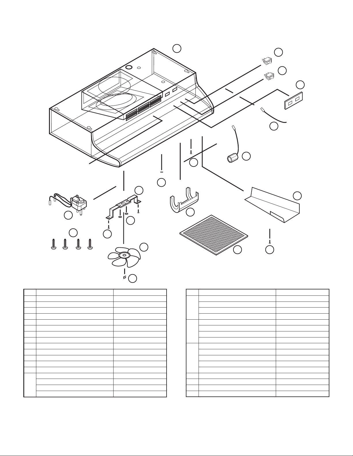
DIAGRAMA DE REPUESTOS
18
17
16
15
14
13
10
12
11
6
9
7
5
19
4
3
2
# Descripción Número de Repuesto
1 Filtro RF55 5S4108001
Tuercas A Presión 5S4199001
2
Aspa del Ventilador 5S4199002
3
Tornillo #8 B 5S1999015
4
Tuerca Hexagonal 5S1999006
5
Ménsula del Motor 5S4199003
6
Lentes de la Luz 5S4199004
7
8
Tornillo #6 AB 5S1999004
Cubierta del Compartimiento de Cable 5S4199005
9
Soporte de la Lámpara 5S4199006
10
Buje 5S1999016
11
12
Tornillo a Tierra #10 5S1999002
Cable de Arranque 5S4199007
13
Placa del Interruptor - Blanco 5S1421003
14
Bizcocho 5S1421004
Almendra 5S1421005
Negro 5S1421006
81
# Descripción Número de Repuesto
15 Interruptor del Motor - Blanco 5S1418003
Bizcocho 5S1418004
Almendra 5S1418005
Negro 5S1418006
Interruptor de la Luz - Blanco 5S1419003
16
Bizcocho 5S1419004
Almendra 5S1419005
Negro 5S1419006
Envoltorio - 21" 5S1425010
17
24" 5S1425020
30" 5S1425030
36" 5S1425040
42" 5S1425050
Motor 5S2199001
18
Tornillo #8 5S1999017
19
Instalador: _______________________________________________________ Fecha de Instalación: _____________________________________
Lugar de Compra: __________________________________________________ Número de Modelo: ______________________________________
6728001 Rev. B 3-07
www.airkinglimited.com
15
Page 16

6728001 Rev. B 3-07
www.airkinglimited.com
16
 Loading...