

Page 1
IMPORTANT INSTRUCTIONS -
OPERATING MANUAL
LIN Series
Powered Liner
READ AND SAVE THESE INSTRUCTIONS
READ CAREFULLY BEFORE ATTEMPTING TO ASSEMBLE, INSTALL, OPERATE OR MAINTAIN THE PRODUCT DESCRIBED.
PROTECT YOURSELF AND OTHERS BY OBSERVING ALL SAFETY INFORMATION. FAILURE TO COMPLY WITH
INSTRUCTIONS COULD RESULT IN PERSONAL INJURY AND/OR PROPERTY DAMAGE!
RETAIN INSTRUCTIONS FOR FUTURE REFERENCE.
GENERAL SAFETY INFORMATION
When using electrical appliances, basic precautions
should always be followed to reduce the risk of fire,
electric shock and injury to person, including the following:
WARNING: TO REDUCE THE RISK OF FIRE, ELECTRIC SHOCK AND
INJURY TO PERSON, OBSERVE THE FOLLOWING:
a) Use this unit only in the manner intended by the manufacturer. If you
have questions, contact the manufacturer.
b) Before servicing or cleaning the unit, switch power off at service panel
and lock the service disconnecting means to prevent power from
being switched on accidentally. When the service disconnecting means
cannot be locked, securely fasten a prominent warning device, such as
a tag, to the service panel.
WARNING: TO REDUCE THE RISK OF FIRE, ELECTRIC SHOCK AND
INJURY TO PERSON, OBSERVE THE FOLLOWING:
a) Installation work and electrical wiring must be done by qualified
person(s) in accordance with all applicable codes and standards,
including fire-related construction.
b) Sufficient air is needed for proper combustion and exhausting of
gases through the flue (chimney) of fuel burning equipment to prevent
back drafting. Follow the heating equipment manufacturer’s guideline
and safety standards such as those published by the National Fire
Protection Association (NFPA) and the American Society for Heating,
Refrigeration, and Air Conditioning Engineers (ASHRAE), and the local
code authorities.
c) When cutting or drilling into wall or ceiling, do not damage electrical
wiring and other hidden utilities.
WARNING: TO REDUCE THE RISK OF FIRE AND TO PROPERLY
EXHAUST AIR, BE SURE TO DUCT AIR OUTSIDE - DO NOT VENT
EXHAUST AIR INTO SPACES WITHIN WALLS OR CEILINGS OR INTO
ATTICS, CRAWL SPACES, OR GARAGES.
d) Ducted fans must always be vented to the outdoors.
e) This unit must be grounded.
f) To avoid motor bearing damage and noisy and/or unbalanced
impellers, keep drywall spray, construction dust, etc. off power unit.
g) Read all instructions before installing or using exhaust fan.
WARNING: TO REDUCE THE RISK OF FIRE, ELECTRIC SHOCK, DO
NOT USE THIS FAN WITH ANY SOLID-STATE SPEED CONTROL DEVICE.
WARNING: TO REDUCE THE RISK OF A RANGE TOP GREASE FIRE:
a) Never leave surface units unattended at high settings. Boilovers
cause smoking and greasy spillovers that may ignite. Heat oils
slowly on low or medium settings.
b) Always turn hood ON when cooking at high heat or when
flambéing food (ie. Crepes Suzette, Cherries Jubilee,
Peppercorn Beef Flambé).
c) Clean ventilating fans frequently. Grease should not be allowed to
accumulate on fan filter.
d) Use proper pan size. Always use cookware appropriate for the size
of the surface element.
WARNING: TO REDUCE THE RISK OF INJURY TO PERSONS IN
THE EVENT OF A RANGE TOP GREASE FIRE, OBSERVE THE FOLLOWING:
a) SMOTHER FLAMES with a close-fitting lid, cookie sheet, or metal
tray, then turn off burner. BE CAREFUL TO PREVENT BURNS. If the
flames do not go out immediately, EVACUATE AND CALL THE FIRE
DEPARTMENT.
b) NEVER PICK UP A FLAMING PAN - You may be burned.
c) DO NOT USE WATER, including wet dishcloths or towels -
a violent steam explosion will result.
d) Use an extinguisher ONLY if:
I. You know you have a Class ABC extinguisher, and you
already know how to operate it.
II. The fire is small and contained in the area where it started.
III. The fire department is being called.
IV. You can fight the fire with your back to an exit.
WARNING: TO REDUCE THE RISK OF FIRE, USE ONLY METAL
DUCTWORK.
SAVE THESE INSTRUCTIONS
6728024M Rev. C 4-12 1 of 12
www.airkinglimited.com
Page 2
INSTALLATION INSTRUCTIONS
CAUTION: MAKE SURE POWER IS SWITCHED OFF AT SERVICE PANEL BEFORE
STARTING INSTALLATION.
NOTE : When installing the Liner outdoors, the Air King Professional Liners are approved for
use in covered outdoor kitchens only. Proper duct adapters, ducting, chimneys, roof/wall
caps, etc. must be utilized as called out in the following instructions. Do not install the liner in
an uncovered area directly exposed to the elements.
Screws
Canopy
Flange
SECTION 1
Preparing the Insert
1. Unpack hood from the carton and confirm that all pieces are present. In addition to the
range hood you should have:
8 - Screws (LIN34, LIN40 models - 12; LIN46, LIN58 models - 14)
2 - Halogen Bulbs (LIN58 models - 4)
1 - Duct Adapter
1 - Grease Trough
2 - Grease Baffles (LIN24, LIN46, LIN58 models - 3)
2 - Spacers (LIN24 models only)
1 - Instruction/Safety Sheet
NOTE: Some hoods may be shipped with a protective plastic adhered to the underside of the
unit. It is recommended to leave this in place during installation to protect it from scratching.
Remove when the installation is complete.
SECTION 2
Preparing the Area
CAUTION: MAKE SURE POWER IS SWITCHED OFF AT SERVICE PANEL BEFORE
STARTING INSTALLATION.
CAUTION: WHEN CUTTING OR DRILLING INTO WALL DO NOT DAMAGE
ELECTRICAL WIRING AND OTHER HIDDEN UTILITIES.
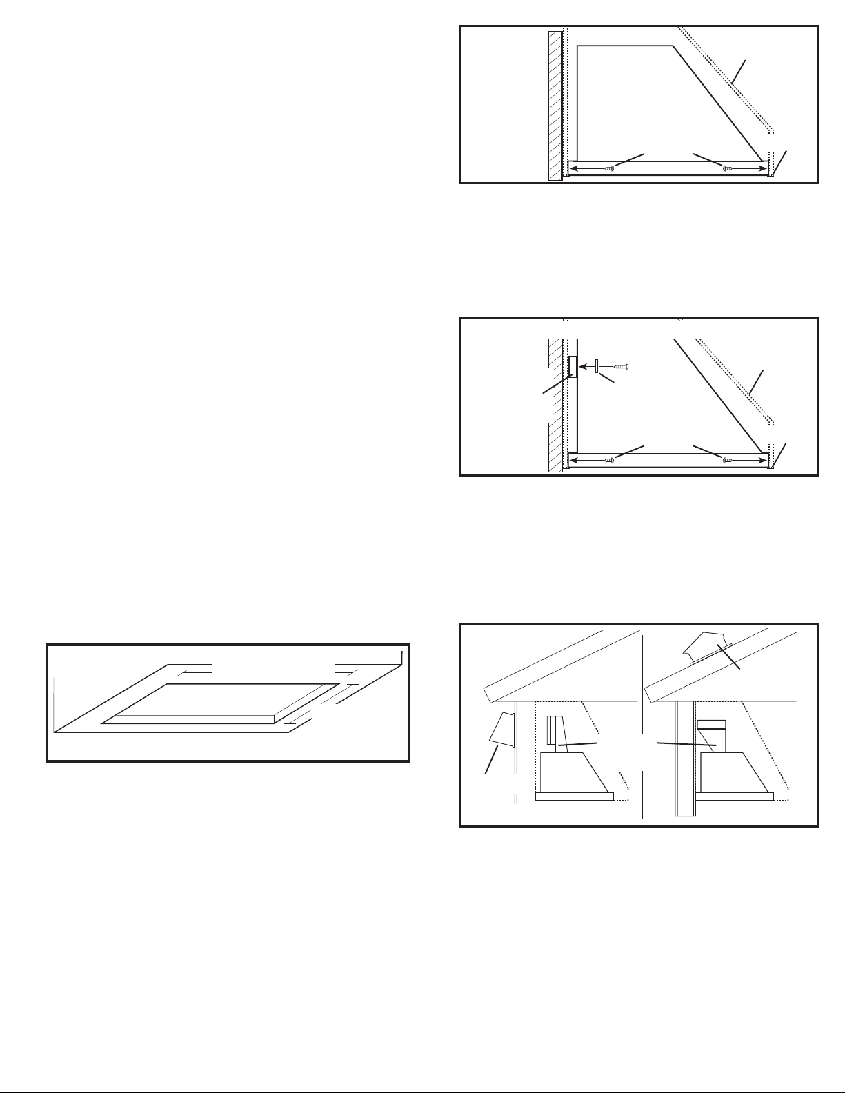
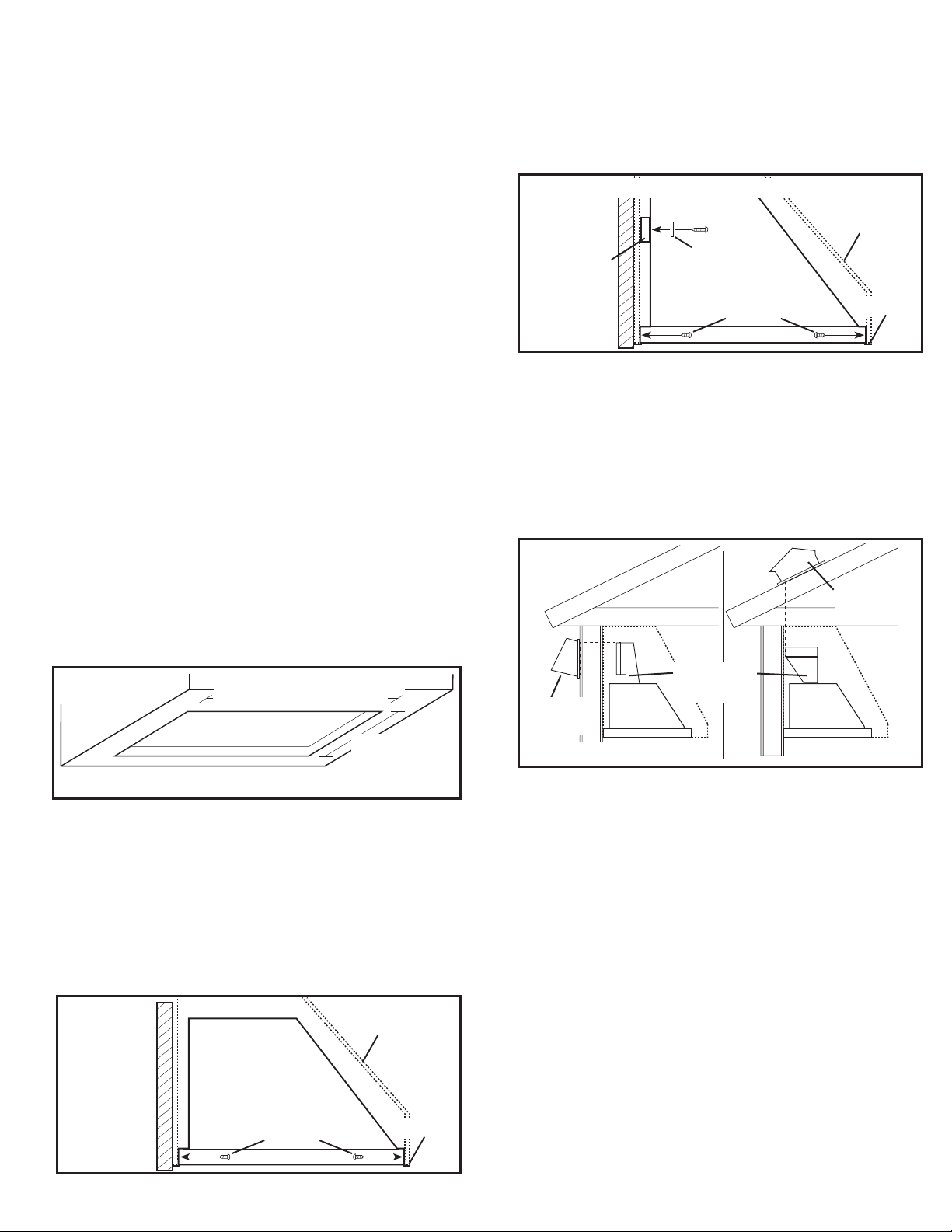
1. Cut an appropriately sized hole for the cabinet or canopy the liner will be mounted into
(Figure 1):
LIN24M models: 24.5" x 19.375" LIN24D models: 24.5" x 22.625"
LIN28M models: 28.5" x 19.375" LIN28D models: 28.5" x 22.625"
LIN34M models: 34.5" x 19.375" LIN34D models: 34.5" x 22.625"
LIN40M models: 40.5" x 19.375" LIN40D models: 40.5" x 22.625"
LIN46M models: 46.5" x 22.625" LIN58M models: 58.5" x 22.625"
24.5"/28.5"/34.5"/
40.5"/ 46.5"/58.5"
Figure 2
NOTE: If additional support is required, install a 2" x .75" strip of wood between the back of
the canopy (rear wall) and the hood. When installing the wood strip to the back of the canopy,
locate studs in the wall to support the weight of the canopy. Center the wood strip 11.5"
from the bottom of the canopy and attach the strip to at least two studs in the rear wall (do
not fasten the strip to drywall only). Lift unit up into position so that the bottom flanges are in
solid contact with the bottom of the canopy or cabinet. Using wood screws and washers (not
included) secure the hood to the wood strip through the two keyholes in the back of the hood.
Using the included wood mounting screws, secure the unit to the canopy or cabinet by driving
the screws through the holes (Figure 3).
OPTIONAL ADDITIONAL SUPPORT
Canopy
Wood
Mounting
Washer
Strip
Screws
Flange
Figure 3
SECTION 4
Ducting
CAUTION: ALL DUCTING MUST COMPLY WITH LOCAL AND NATIONAL
BUILDING CODES.
WARNING: TO REDUCE THE RISK OF FIRE, USE ONLY METAL DUCTWORK.
1. Determine the type of ducting you will require (Figure 4).
Horizontal
Roof Cap
19.375"
22.625"
Figure 1
Outlet
Adapter
NOTE: The hood must be mounted a minimum of 24" and a maximum of 36" from the
cooking surface.
SECTION 3
Mounting the Liner
CAUTION: DUE TO THE WEIGHT AND BULK OF THE UNIT, IT IS RECOMMENDED
THAT THREE PEOPLE ARE PRESENT DURING INSTALLATION TO LIFT, HOLD, AND SECURE
THE UNIT IN PLACE.
1. Lift unit up into position so that the bottom flanges are in solid contact with the bottom of
the canopy or cabinet. Using the included wood mounting screws, secure the unit to the
canopy or cabinet by driving the screws through the holes (Figure 2).
6728024M Rev. C 4-12 2 of 12
www.airkinglimited.com
Wall Cap
Figure 4
NOTE: For models using the B300, B500, and B600 blowers, a minimum of 6" diameter outlet
adapter & ducting is required to achieve the proper air flow. The B900 requires a minimum of 8"
diameter adapter and ducting. The B1125 requires a minimum 10" diameter adapter and ducting.
NOTE: When the duct termination is similar to that shown in Figure 4 (passing through the wall
to which the hood is mounted) the installation requires special consideration. Depending upon
where the wall studs are located, it may be necessary to cut one or more of the wall studs and
install a header and footer to transfer the load to the adjacent studs. Additional studs may need
to be framed into the opening to attach dry wall or secure the hood. If this is your situation Air
King recommends that you hire a professional and comply with all applicable codes.
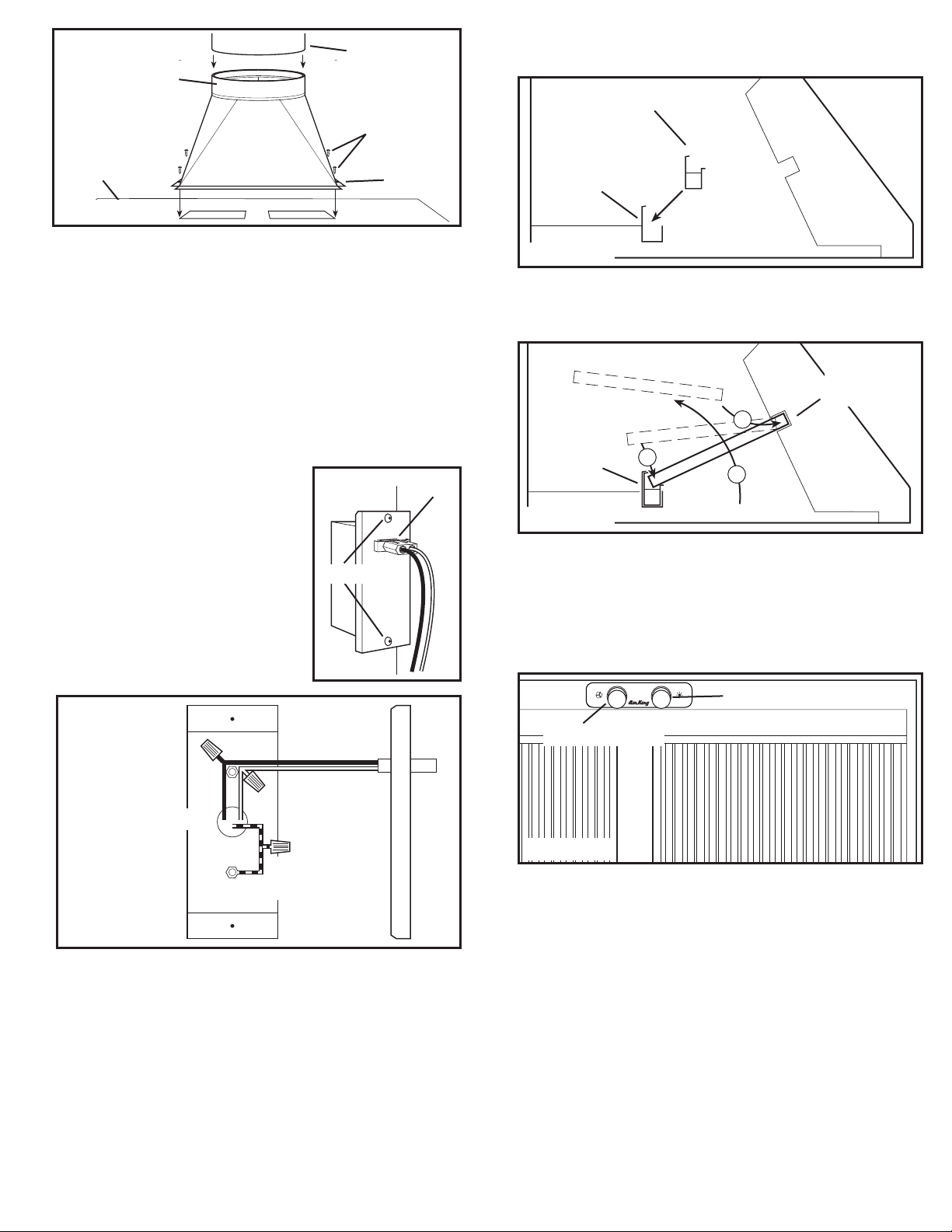
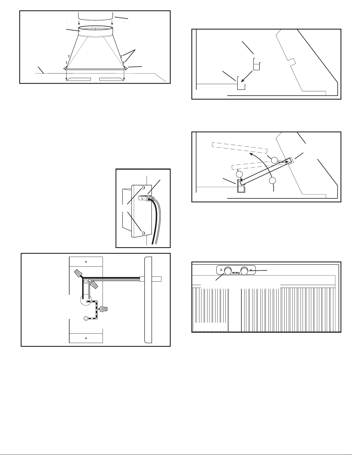
2. Install the proper sized outlet adapter to the hood by matching up the four holes on the
flange of the adapter to the four corresponding holes on the hood and secure in place
with the provided screws. Ensure an airtight seal around the adapter by securing all
connections with ducting tape (Figure 5).
Vertical
Page 3
Outlet Adapter
Ducting
Screws
2. If the included removable grease trough is not already installed within the hood, insert
into the rear inside channel of the hood. Make sure the taller side of the trough is facing
towards the back of the hood (Figure 8).
Grease Trough
Hood
Flange
Figure 5
3 When there is access to the top of the unit, connect the ducting to the duct collar and
secure in place using tape to seal all joints (Figure 5).
4. When there is no access to the top of the hood, carefully pull down the metal duct
through the custom hood base hole. Slide this duct over the duct collar. Make sure the
adapter/damper assembly enters the ducting. Seal the connection with duct tape.
SECTION 5
Wiring
CAUTION: ALL ELECTRICAL CONNECTIONS MUST BE MADE IN
ACCORDANCE WITH LOCAL CODES, ORDINANCES, OR NATIONAL ELECTRICAL CODE. IF
YOU ARE UNFAMILIAR WITH METHODS OF INSTALLING ELECTRICAL WIRING, SECURE THE
SERVICES OF A QUALIFIED ELECTRICIAN.
1. Remove the two wire compartment cover screws
to gain access into the wire compartment (Figure
6). Connect the white wire from the range hood to
the white wire from the supply, and the black wire
from the range hood to the black wire of the supply.
Connect the ground wire from the home (green or
bare) to the ground wire (green) from the hood. Use
approved methods for all connections (Figure 7).
2. Replace the wire compartment cover and tighten
screws. Make sure all wiring is securely contained
within the wire compartment. If the quick connect
wire connector was removed from the receptacle,
replace. The connector will only fit one way into the
receptacle (Figure 6).
Wire Connector
Screws
Figure 6
Channel
Figure 8
3. Install the baffle filters and any spacers included with the unit by inserting the top of the filter
into the top channel of the hood, then slide the bottom of the filter into the bottom channel.
The filters have a top and a bottom. The bottom of the filter will have small drain holes.
These holes must be facing down towards the grease trough to be effective (Figure 9).
Top
Bottom
Channel
2
Channel
3
1
Figure 9
SECTION 8
Operation
Controls
Your Liner is equipped with two rotary switches with one controlling the lighting and the other
controlling the exhaust fan blower. The light switch has three positions, High, Low, and Off.
The fan switch has four positions, Off, High, Medium, and Low (Figure 10).
Light Switch
Hot (Black)
Neutral
(White)
Supply from house
Ground
(Green or Bare)
Figure 7
SECTION 6
Installing the Blower
1. Refer to the instructions included with the specific blower you have chosen for installation.
SECTION 7
Finishing the Installation
1. Install the proper lighting for your specific unit:
Halogen Lamps: Use PAR16 medium base 45W maximum Halogen lamps. Install
by inserting lamp into socket and turning clockwise until lamp is firmly seated. DO
NOT over tighten.
Blower Switch
Figure 10
Thermostat
Your Liner is equipped with a thermostat that will automatically turn the Liner on when the
temperature exceeds a set point. Once the temperature drops, the thermostat will turn the Liner off.
CAUTION: THE LINER SHOULD ALWAYS BE TURNED ON OR OFF USING THE
CONTROL PANEL ANYTIME THE COOKING SURFACE IS BEING USED. DO NOT RELY ON THE
THERMOSTAT AS THE SOLE MEANS OF TURNING THE LINER ON OR OFF!
SECTION 9
Maintenance
CAUTION: MAKE SURE POWER IS SWITCHED OFF AT SERVICE PANEL BEFORE
SERVICING THE UNIT.
Grease Baffles
Included with your range hood are stainless steel grease baffles along with a grease trough
that should be washed at least once a month. The baffles and trough are dishwasher safe and
should be washed in a mild soap or detergent. Reverse the instruction in SECTION 8 Finishing
the Installation, to remove baffles and trough. If the grease baffles become damaged, replace
with the appropriate Air King Grease Baffles as described in the parts diagram.
6728024M Rev. C 4-12 3 of 12
www.airkinglimited.com
Page 4
CAUTION: ALLOW BULB TO COOL BEFORE REPLACING.
Changing the Lamps
Remove the lamp by turning slightly counter-clockwise and pulling out of the socket. Replace
with a PAR16 medium base 45W maximum Halogen lamp.
Fuse
To replace the fuse, turn the fuse cap located next to the wire connector counter clockwise
and pull out. Replace with the proper fuse specific to your blower. Reinstall the fuse back into
the hood.
Cleaning
CAUTION: DO NOT USE GASOLINE, BENZINE, THINNER, HARSH CLEANSERS,
ETC., AS THEY MAY DAMAGE THE RANGE HOOD.
1. Clean your power unit with a mild detergent, such as dishwashing liquid, and dry with a soft
cloth. NEVER USE ANY ABRASIVE PADS OR SCOURING POWDERS. Completely dry before
restoring power. NEVER IMMERSE ELECTRICAL PARTS IN WATER.
2. The fan assembly can be vacuumed when build up (dirt, lint, etc.) accumulates over time.
The fan is permanently lubricated and does not require oiling.
Troubleshooting Guide
Trouble Probable Cause Suggested Remedy
1. Hood does not operate when the switch is on. 1a. A fuse may be blown or a circuit tripped. 1a. Replace fuse or reset circuit breaker.
1b. Wiring is not connected properly. 1b. Turn off power to unit. Check that all wires are connected.
2. Hood is operating, but air moves slower than normal. 2. Obstruction in the exhaust ducting. 2. Check for any obstructions in the ducting including filter.
3. Hood is making a rattling noise. 3a. Filters are loose. 3a. Turn off power to unit. Check that all filter screws are fully tightened.
3b. Duct connection is loose. 3b. Turn off power to unit. Check that duct connection is tight.
3c. Damper is stuck. 3c. Turn off power to unit. Check that the damper is opening freely.
LIMITED WARRANTY
WHAT THIS WARRANTY COVERS: This product is warranted against defects in workmanship and/or materials.
HOW LONG THIS WARRANTY LASTS: This warranty extends only to the original purchaser of the product and lasts for one (1) year from the date of original purchase or until the original
purchaser of the product sells or transfers the product, whichever first occurs.
WHAT AIR KING WILL DO: During the warranty period, Air King will, at its sole option, repair or replace any part or parts that prove to be defective or replace the whole product with the
same or comparable model.
WHAT THIS WARRANTY DOES NOT COVER: This warranty does not apply if the product was damaged or failed because of accident, improper handling or operation, shipping damage, abuse,
misuse, unauthorized repairs made or attempted. This warranty does not cover shipping costs for the return of products to Air King for repair or replacement. Air King will pay return shipping
charges from Air King following warranty repairs or replacement
ANY AND ALL WARRANTIES, EXPRESSED OR IMPLIED (INCLUDING, WITHOUT LIMITATION, ANY IMPLIED WARRANTY OF MERCHANTABILITY), LAST ONE YEAR FROM THE DATE
OF ORIGINAL PURCHASE OR UNTIL THE ORIGINAL PURCHASER OF THE PRODUCT SELLS OR TRANSFERS THE PRODUCT, WHICHEVER FIRST OCCURS AND IN NO EVENT SHALL AIR
KING’S LIABILITY UNDER ANY EXPRESS OR IMPLIED WARRANTY INCLUDE (I) INCIDENTAL OR CONSEQUENTIAL DAMAGES FROM ANY CAUSE WHATSOEVER, OR (II) REPLACMENT
OR REPAIR OF ANY HOUSE FUSES, CIRCUIT BREAKERS OR RECEPTACLES. NOTWITHSTANDING ANYTHING TO THE CONTRARY, IN NO EVENT SHALL AIR KING’S LIABILITY UNDER ANY
EXPRESS OR IMPLIED WARRANTY EXCEED THE PURCHASE PRICE OF THE PRODUCT AND ANY SUCH LIABILITY SHALL TERMINATE UPON THE EXPIRATION OF THE WARRANTY
PERIOD.
Some states and provinces do not allow limitations on how long an implied warranty lasts, or the exclusion or limitation of incidental or consequential damages, so these exclusions or limitations
may not apply to you. This warranty gives you specific legal rights. You may also have other rights which vary from state to state and province to province. Proof of purchase is required before a
warranty claim will be accepted.
CUSTOMER SERVICE:
Our Customer Service team is available to assist you with product questions, service center locations, and replacement parts. They can be reached Monday through Friday, 8am-4pm Eastern.
Please have your model number available, as well as the type and style (located on the label inside of your product).
Please do not return product to place of purchase.
PARTS FOR DISCONTINUED, OBSOLETE AND CERTAIN OTHER PRODUCTS MAY NOT BE AVAILABLE. DUE TO SAFETY REASONS, MANY ELECTRONIC COMPONENTS AND MOST
HEATER COMPONENTS ARE NOT AVAILABLE TO CONSUMERS FOR INSTALLATION OR REPLACEMENT.
Toll-Free (800) 465-7300
www.airkinglimited.com
Installer: Installation Date:
Place of Purchase: Model Number:
6728024M Rev. C 4-12 4 of 12
www.airkinglimited.com
Page 5
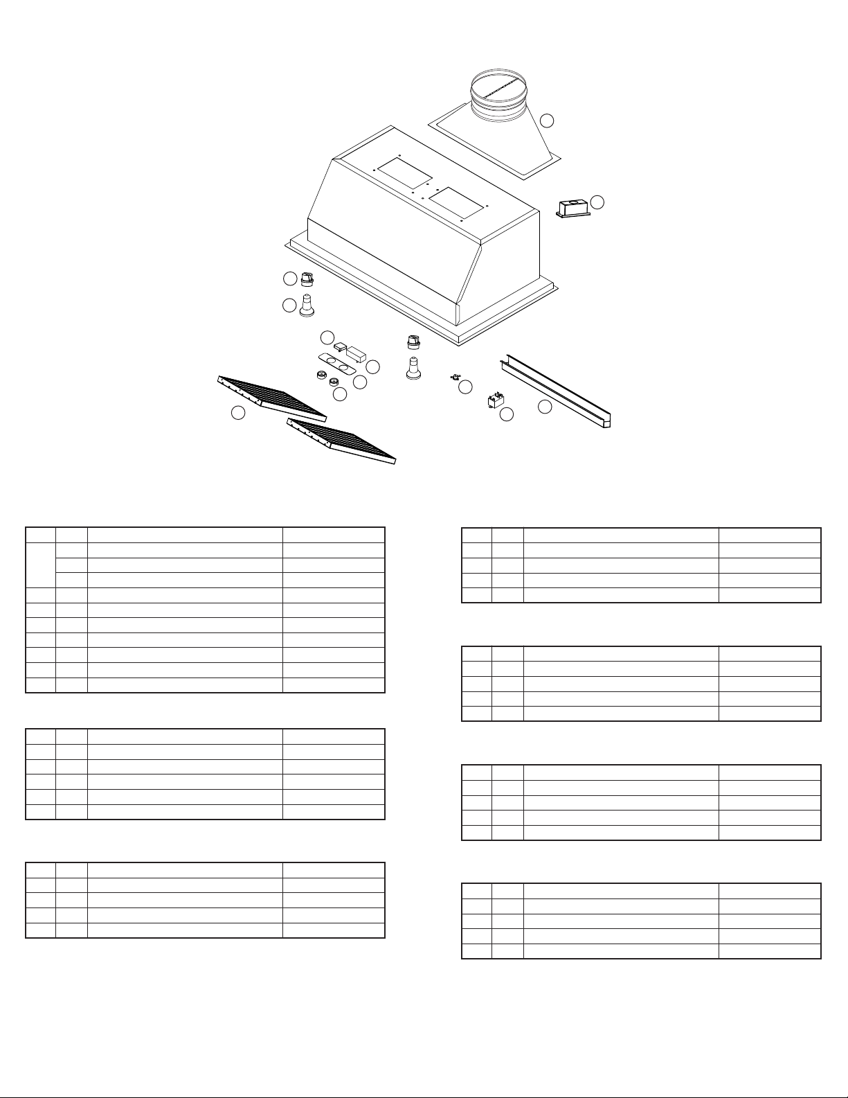
REPLACEMENT PARTS DIAGRAM
1
2
9
10
3
4
5
6
11
7
12
8
ALL LIN MODELS
# Qty. Description Replacement Part #
1 1 Vertical Duct Adapter (300, 500, 600 CFM) 5S1136141
1 Vertical Duct Adapter (900 CFM) 5S1136142
1 Vertical Duct Adapter (1200 CFM) 5S1136143
2 1 Wire Box 5S1136064
3 1 Fan Switch 5S1136070
4 1 Light Switch 5S1141013
5 1 Switch Plate 5S1142010
6 2 Knob 5S1142011
7 1 Thermostat 5S1141012
8 1 Relay 5S1239008
LIN24 MODELS
# Qty. Description Replacement Part #
9 2 Lamp Holder 5S1136075
10 2 45w PAR16 Bulb 5S1136099
11 3 Baffle Filter - PHGB1 5S1136077
12 1 Grease Tray 5S1141320
2 Filter Spacer 5S1141221
LIN28 MODELS
# Qty. Description Replacement Part #
9 2 Lamp Holder 5S1136075
10 2 45w PAR16 Bulb 5S1136099
11 2 Baffle Filter - PHGB2 5S1136078
12 1 Grease Tray 5S1141370
LIN34 MODELS
# Qty. Description Replacement Part #
9 2 Lamp Holder 5S1136075
10 2 45w PAR16 Bulb 5S1136099
11 2 Baffle Filter - PHGB3 5S1136079
12 1 Grease Tray 5S1136135
LIN40 MODELS
# Qty. Description Replacement Part #
9 2 Lamp Holder 5S1136075
10 2 45w PAR16 Bulb 5S1136099
11 2 Baffle Filter - PHGB3 5S1136079
12 1 Grease Tray 5S1136135
LIN46 MODELS
# Qty. Description Replacement Part #
9 2 Lamp Holder 5S1136075
10 2 45w PAR16 Bulb 5S1136099
11 3 Baffle Filter - PHGB3 5S1136079
12 1 Grease Tray 5S1136139
LIN58 MODELS
# Qty. Description Replacement Part #
9 2 Lamp Holder 5S1136075
10 3 45w PAR16 Bulb 5S1136099
11 3 Baffle Filter - PHGB3 5S1136079
12 1 Grease Tray 5S1136139
6728024M Rev. C 4-12 5 of 12
www.airkinglimited.com
Page 6

NOTES
6728024M Rev. C 4-12 6 of 12
www.airkinglimited.com
Page 7
INSTRUCTIONS IMPORTANTES –
MODE D’EMPLOI
Série LIN
Revêtements alimentés
LIRE ET CONSERVER CES INSTRUCTIONS
LIRE SOIGNEUSEMENT AVANT DE TENTER D’ASSEMBLER, INSTALLER, OPÉRER OU DE RÉPARER LE PRODUIT DÉCRIT.
PROTÉGEZ VOUS-MÊME ET LES AUTRES EN OBSERVANT TOUTE L’INFORMATION DE SÉCURITÉ. FAILLIR À SE CONFORMER
AUX INSTRUCTIONS PEUT RÉSULTER EN BLESSURE PERSONNELLE GRAVE ET/OU EN DOMMAGE À LA PROPRIÉTÉ.
CONSERVER CES INSTRUCTIONS POUR RÉFÉRENCES FUTURES.
INSTRUCTIONS GÉNÉRALES DE SÉCURITÉ
Lors de l’utilisation d’appareils électriques, des précautions de base doivent
toujours être suivies pour réduire les risques d’incendie, de choc
électrique et de blessures corporelles, incluant ce qui suit:
AVERTISSEMENT: POUR RÉDUIRE LES RISQUES
D’INCENDIE, DE CHOC ÉLECTRIQUE OU DE BLESSURES PERSONNELLES
OBSERVER CE QUI SUIT:
a) Utiliser cette unité seulement de la manière pour laquelle le fabricant
l’a conçu. Si vous aviez des questions, veuillez contacter le fabricant.
b) Avant d’effectuer un service ou de nettoyer l’unité, couper l’alimentation
électrique dans le panneau de distribution et verrouiller le dispositif de
déconnexion afin d’éviter que l’alimentation ne revienne accidentellement.
Lorsque le dispositif ne peut être verrouillé, fixer solidement un avis
d’avertissement, tel qu’une étiquette, au panneau de distribution.
AVERTISSEMENT: POUR RÉDUIRE LES RISQUES
D’INCENDIE, DE CHOC ÉLECTRIQUE OU DE BLESSURES PERSONNELLES
OBSERVER CE QUI SUIT:
a) Le travail d’installation et le câblage électrique doivent être effectués
par une(des) personne(s) qualifiée(s) en conformité avec tous les codes
et normes applicables, incluant la construction relative aux incendies.
b) De l’air en quantité suffisante est requis pour la bonne combustion
et l’évacuation de gaz par le conduit (cheminée) provenant
d’équipement de brûlage au combustible pour prévenir un refoulement.
Suivre les directives du fabricant de l’équipement de chauffage et
les normes de sécurité telles que celles publiées par la National Fire
Protection Association (NFPA) et de la American Society for Heating,
Refrigeration, and Air Conditioning Engineers (ASHRAE), et de celles
des autorités locales du code.
c) Lorsque vous coupez ou perforez un mur ou un plafond, prenez garde
de ne pas endommager les fils électriques ou tout appareil qui pourrait
être dissimulé.
AVERTISSEMENT: POUR RÉDUIRE LES RISQUES
D’INCENDIE ET POUR ÉVACUER L’AIR ADÉQUATEMENT, ASSUREZ-VOUS
D’ÉVACUER L’AIR VERS L’EXTÉRIEUR – NE PAS ÉVACUER L’AIR DANS
DES ESPACES DANS LES MURS, LES PLAFONDS OU LES GRENIERS, LES
GALERIES TECHNIQUES OU LES GARAGES.
d) Les ventilateurs avec conduits doivent toujours être évacués vers
l’extérieur.
e) Cette unité doit être mise à la terre.
f) Pour éviter des dommages aux roulements des moteurs et/ou des
hélices bruyantes ou déséquilibrées, empêcher la poussière de cloison
sèche, poussière de construction, etc., d’atteindre l’unité de puissance.
g) Lire toutes les instructions avant d’installer ou d’utiliser la hotte de cuisine.
AVERTISSEMENT: POUR RÉDUIRE LES RISQUES
D’INCENDIE OU DE CHOC ÉLECTRIQUE, NE PAS UTILISER CE
VENTILATEUR AVEC UN RÉGULATEUR DE VITESSE ÉLECTRONIQUE.
AVERTISSEMENT: POUR RÉDUIRE LES RISQUES
D’INCENDIE DE GRAISSE SUR LE DESSUS DE LA CUISINIÈRE:
a) Ne jamais laisser les unités de surface à des degrés élevés sans
surveillance. Les débordements par bouillonnement produisent de
la fumée et des débordements graisseux qui peuvent s’enflammer.
Chauffer les huiles lentement à des degrés faibles ou modérés.
b) Toujours mettre la hotte EN MARCHE lors de cuisson à haute
température ou lors de flambage de nourriture (par ex., des
Crêpes Suzette, de Cerises Jubilées, steak flambé, etc.)
c) Nettoyer les ventilateurs d’évacuation fréquemment. Aucune
accumulation de graisse ne devrait être tolérée sur les filtres du
ventilateur.
d) Utiliser des poêlons de taille appropriée. Toujours utiliser les batteries
de cuisine appropriées pour la taille de l’élément de surface.
AVERTISSEMENT: POUR RÉDUIRE LES RISQUES DE
BLESSURES PERSONNELLES DANS L’ÉVENTUALITÉ D’UN FEU DE GRAISSE
SUR LA SURFACE DE CUISSON, SUIVRE LES INDICATIONS SUIVANTES:
a) ÉTOUFFER LES FLAMMES avec un couvercle bien ajusté, une
tôle à biscuits, ou un cabaret de métal, puis, mettre le gril hors
fonction. PRENEZ SOIN D’ÉVITER LES BRÛLURES. Si les flammes
ne s’éteignent pas immédiatement, ÉVACUER ET APPELER LE
SERVICE DES INCENDIES.
b) NE JAMAIS SAISIR UN POÊLON EN FLAMME – vous pourriez être
brûlé.
c) NE PAS UTILISER DE L’EAU, incluant les linges à vaisselle ou les
serviettes mouillées – il en résulterait une violente explosion de
vapeur.
d) Utiliser un extincteur SEULEMENT SI:
I. Vous savez que vous avez un extincteur de classe ABC, et
que vous savez déjà comment l’opérer.
II. Le feu est petit et contenu dans la zone où il a commencé.
III. On appelle le service des incendies.
IV. Vous pouvez combattre l’incendie avec une sortie derrière vous.
AVERTISSEMENT: POUR RÉDUIRE LES RISQUES
D’INCENDIE, UTILISER UNIQUEMENT DES CONDUITS EN MÉTAL.
CONSERVER CES INSTRUCTIONS
6728024M Rev. C 4-12 7 of 12
www.airkinglimited.com
Page 8
INSTRUCTIONS POUR L’INSTALLATION
AVERTISSEMENT :
COUPÉE AU PANNEAU DE SERVICE AVANT DE COMMENCER L’INSTALLATION.
REMARQUE : Lorsque vous installez le revêtement à l’extérieur, les revêtements
professionnels d’Air King sont approuvés pour une utilisation dans les cuisines couvertes à
l'extérieur seulement. Vous devez utiliser les adaptateurs de conduit, conduits, cheminées,
couvertures de toit/mur, etc. appropriées selon les instructions suivantes. N'installez pas le
revêtement dans une zone à découvert directement exposé aux éléments.
VOUS ASSURER QUE L’ALIMENTATION EST
REMARQUE : Si vous avez besoin d’un support additionnel, installez une bande en bois de 2 po
X .75 po entre le dos de l’armoire (mur arrière) et la hotte. En installant la bande en bois sur le
dos de l’armoire, localisez les goujons dans le mur pour soutenir le poids de l’armoire. Centrez
la bande en bois à 11.5 po du fond de l’armoire et attachez la bande à au moins deux goujons
dans le mur arrière (n'attachez pas la bande à la cloison sèche seulement). Soulevez l'unité
vers le haut et placez-la de sorte que les arêtes du fond soient en plein contact avec le fond de
l’armoire. Utilisant des vis en bois et des rondelles (non incluses) fixez la hotte à la bande en
bois par les deux trous dans le dos de la hotte. En utilisant les vis de support en bois incluses,
fixez l'unité dans l’armoire en enfonçant les vis à l’intérieur des trous (Figure 3).
SECTION 1
Préparation de l’insert
1. Sortez la hotte de l’emballage et assurez-vous d’avoir toutes les pièces. En plus de la
hotte, vous devriez avoir :
8 - Vis (modèles LIN34, LIN40 - 12 ; modèles LIN46, LIN58 - 14)
2 - Lampes halogènes (modèle LIN58 - 4)
1 - Adaptateur de sortie
1 - Dalot à graisse
2 - Déflecteurs de graisse (modèles LIN24, LIN46, LIN58 - 3)
2 - Entretoises (modèles LIN24 seulement)
1 - Instructions et mesures de sécurité
REMARQUE : Certaines hottes peuvent être expédiées avec protecteur en plastique collé à
la hotte. Il est recommandé de le laisser en place durant l’installation pour protéger la hotte
contre les égratignures. Enlever une fois l’installation complétée.
SECTION 2
Préparation de la région
AVERTISSEMENT : VOUS ASSURER QUE L’ALIMENTATION EST
COUPÉE AU PANNEAU DE SERVICE AVANT DE COMMENCER L’INSTALLATION.
AVERTISSEMENT : LORS DE DECOUPE OU DE PERCAGE DANS UN
MUR NE PAS ENDOMMAGER DE FILAGE ELECTRIQUE OU AUTRES UTILITES DISSIMULEES.
1. Taillez un trou d’une grandeur appropriée pour l’armoire dans lequel le revêtement sera
monté (Figure 1) :
Modèles LIN24M : 24.5 po x 19.375 po Modèles LIN24D : 24.5 po x 22.625 po
Modèles LIN28M : 28.5 po x 19.375 po Modèles LIN28D : 28.5 po x 22.625 po
Modèles LIN34M : 34.5 po x 19.375 po Modèles LIN34D : 34.5 po x 22.625 po
Modèles LIN40M : 40.5 po x 19.375 po Modèles LIN40D : 40.5 po x 22.625 po
Modèles LIN46M : 46.5 po x 22.625 po Modèles LIN58M : 58.5 po x 22.625 po
24.5 po/28.5 po/34.5 po/
40.5 po/ 46.5 po/58.5 po
19.375 po
22.625 po
Figure 1
REMARQUE : La hotte doit être montée à un minimum de 24 po et à un maximum de 36 po
de la surface de cuisson.
SECTION 3
Montage du revêtement
AVERTISSEMENT : EN RAISON DU POIDS ET DE LA GRANDEUR DE
L'UNITÉ, ON VOUS RECOMMANDE QUE TROIS PERSONNES SOIENT PRÉSENTES PENDANT
L'INSTALLATION POUR SOULEVER, TENIR, ET FIXER L'UNITÉ EN PLACE.
1. Soulevez l'unité vers le haut et placez-la de sorte que les arêtes inférieures soient en
plein contact avec le fond de l’armoire. En utilisant les vis de support en bois incluses,
fixez l'unité dans l’armoire en enfonçant les vis à l’intérieur des trous (Figure 2).
Armoire
SUPPORT ADDITIONNEL FACULTATIF
Armoire
Bande de
Rondelle
montage en
bois
Vis
Bride
Figure 3
SECTION 4
Conduits
AVERTISSEMENT : TOUS LES CONDUITS DOIVENT ÊTRE
CONFORMES AUX CODES LOCAL ET NATIONAL DU BÂTIMENT.
AVERTISSEMENT : POUR RÉDUIRE LES RISQUES D’INCENDIE
UTILISER UNIQUEMENT DES CONDUITS EN MÉTAL.
1. Déterminer le type de conduits dont vous aurez besoin (Figure 4).
Horizontal
Chapeau
de toit
Adaptateur
Chapeau
mural
Figure 4
REMARQUE : Pour des modèles utilisant le ventilateur B300, B500 ou B600, un conduit
et un adaptateur de sortie de 6 po de diamètre au minimum sont exigés pour obtenir la
circulation d'air appropriée. Le B900 exige un conduit et un adaptateur de sortie de 8 po de
diamètre au minimum. Le B1125 exige un conduit et un adaptateur de sortie de 10 po de
diamètre au minimum.
REMARQUE : Lorsque la terminaison du conduit est similaire à celle illustrée à la figure
4 (passant au travers du mur sur lequel la hotte est installée) l’installation requiert une
considération spéciale. Dépendant de où les montants muraux sont situés, il peut être
nécessaire de couper un montant mural ou plus et d’installer une chevêtre et une assise
pour transférer la charge aux montants adjacents. Des montants additionnels pourraient
devoir être bâtis dans l’ouve-rture pour fixer la cloison sèche et pour fixer la hotte. Si vous
rencontrez cette situation, Air King recommande que vous embauchiez un professionnel et
que vous vous conformiez avec tous les codes du bâtiment applicables.
2. Installer l’adaptateur mural de la bonne taille requise à la hotte en appariant les quatre
trous sur la bride de l’adaptateur aux quatre trous correspondants sur la hotte et
fixer en place avec les vis comprises. Assurez-vous que le joint est étanche autour de
l’adaptateur en sécurisant tous les raccords avec du ruban de gaine (Figure 5).
de sortie
Vertical
Vis
Bride
Figure 2
6728024M Rev. C 4-12 8 of 12
www.airkinglimited.com
Page 9
Adaptateur de
sortie
Conduit
Vis
2. Si le dalot à graisse rétractable compris n’est pas déjà installé dans la hotte, l’insérer
dans le canal intérieur arrière de la hotte. Assurez-vous que le côté le plus long du dalot
fait face vers l’arrière de la hotte (Figure 8).
Dalot à graisse
Hotte
Bride
Figure 5
3 Quand il y a accès au dessus de l’unité, reliez la canalisation au collier de conduit et
fixez-la en place en utilisant un ruban adhésif pour sceller tous les joints (Figure 5).
4. Quand il n’y a aucun accès au dessus de la hotte, abaissez soigneusement le conduit
en métal par le trou à la base de la hotte. Glissez ce conduit au-dessus du collier de
conduit. Assurez-vous que l’assemblement de la pièce d’ajustage / du clapet entre dans
la canalisation. Scellez le raccordement avec le ruban adhésif de conduit.
SECTION 5
Câblage
AVERTISSEMENT : TOUTES LES CONNEXIONS DOIVENT ÊTRE FAITES
EN CONFORMITÉ AVEC LES CODES ÉLECTRIQUES LOCAUX OU NATIONAUX. SI VOUS
N’ÊTES PAS FAMILIER AVEC LES MÉTHODES D’INSTALLATION DE CÂBLAGE ÉLECTRIQUE,
RECOURREZ AUX SERVICES D’UN ÉLECTRICIEN QUALIFIÉ.
1. Enlever les deux vis du couvercle du compartiment
de câblage pour obtenir l’accès au compartiment de
câblage (Figure 6). Raccorder le fil blanc de la hotte
au fil blanc de l’alimentation, et le fil noir de la hotte
au fil noir de l’alimentation. Raccorder le fil de mise
à la terre de la maison (fil nu ou vert) au fil de mise
à la terre (vert) de la hotte. Utiliser des méthodes
approuvées pour toutes les connexions (Figure 7).
2. Replacer le couvercle du compartiment de câblage
et serrer les vis. Assurez-vous que tout le câblage
est fermement contenu dans le compartiment à
câblage. Si le connecteur rapide de fils a été enlevé
du réceptacle, le replacer. Le connecteur ne s’ajustera
que d’une seule façon dans le réceptacle (Figure 6).
Connecteur à fils
Vis
Figure 6
Canal
Figure 8
3. Installez les filtres à chicanes et toutes les entretoises inclus avec l'unité en insérant le
dessus du filtre dans le canal supérieur du capot, puis faites glisser le bas du filtre dans
le canal inférieur. Les filtres comprennent un dessus et un dessous. Le dessous du filtre
aura des trous de vidange de petite taille. Ces trous doivent être orientés vers le bas vers
le collecteur de graisse pour être efficace (Figure 9).
Canal du
haut
2
Canal du
bas
3
1
Figure 9
SECTION 8
Operation
Contrôles
Votre revêtement est équipée avec deux interrupteurs rotatifs dont l’un contrôle l’éclairage
et l’autre contrôle la soufflante du ventilateur d’évacuation. L’interrupteur de l’éclairage a
3 positions, Haute, Basse, et Éteinte. Le commutateur de vitesse du ventilateur a quatre
positions, Éteinte, Haute, Moyenne, et Basse (Figure 10).
Vivant (noir)
Neutre
(blanc)
Alimentation
provenant de
la maison
Terre (Vert ou
nu)
Figure 7
SECTION 6
Installation de la soufflante
1. Référez-vous aux instructions comprises avec la soufflante spécifique que vous avez
choisie pour l’installation.
SECTION 7
Terminer l’installation
1. Installer le bon éclairage pour votre unité spécifique :
Lampes halogènes : Utiliser des lampes PAR16, de base moyenne, d’un maximum
de 45 watts. L’installer en insérant la lampe dans le réceptacle et en tournant en sens
horaire jusqu’à ce que la lampe soit fermement installée. NE PAS serrer à outrance.
Interrupteur d’éclairage
Interrupteur du ventilateur
Figure 10
Thermostat
Votre revêtement est équipé d'un thermostat qui allumera automatiquement le revêtement
quand la température dépasse un point déterminé. Une fois que la température s'abaisse, le
thermostat éteindra le revêtement.
AVERTISSEMENT : LE REVÊTEMENT DOIT TOUJOURS ÊTRE ACTIVÉ
OU DÉSACTIVÉE PAR LE PANNEAU DE CONTROLE LORSQUE LA SURFACE À CUIRE EST
UTILISÉE. NE COMPTEZ PAS SUR LE THERMOSTAT COMME LE SEUL MOYEND’ALLUMER
OU D’ÉTEINDER LE REVÊTEMENT !
6728024M Rev. C 4-12 9 of 12
www.airkinglimited.com
Page 10
SECTION 9
Maintenance
AVERTISSEMENT : VOUS ASSURER QUE L’ALIMENTATION EST
COUPÉE AU PANNEAU DE SERVICE AVANT DE FAIRE L’ENTRETIEN SUR L’UNITÉ.
Déflecteurs de graisse
Vous trouverez, incluses avec votre hotte de cuisinière, des chicanes de graisse en acier
inoxydable avec une cuvette de graisse qui devrait être lavée au moins une fois par mois. Les
chicanes et la cuvette sont lavables au lave-vaisselle et devraient être lavées avec un savon ou
un détergent doux. Inversez les instructions à la SECTION 8 Fin de l'installation, pour enlever
des chicanes et la cuvette. Si les chicanes de graisse deviennent endommagées, remplacez-les
par les chicanes de graisse Air King appropriées décrites dans le schéma des pièces.
AVERTISSEMENT : LAISSER REFROIDIR LA LAMPE AVANT DE LA
REMPLACER.
Changement de la lampe
Enlevez la lampe en tournant légèrement dans le sens contraire des aiguilles d’une montre
et retirez de la douille. Remplacez par une lampe halogène de base moyenne PAR16, de 45W
au maximum.
Fusible
Pour remplacer le fusible, tournez le bouchon de fusible situé à côté du capuchon de
connexion dans le sens inverse des aiguilles d’une montre et retirez. Référez-vous aux
instructions incluses avec le ventilateur spécifique que vous avez choisi pour l’information sur
le changement du fusible.
Nettoyage
AVERTISSEMENT : NE PAS UTILISER D’ESSENCE, BENZÈNE,
DILUANT, DE NETTOYANT FORT, ETC., PUISQU’ILS POURRAIENT ENDOMMAGER LA HOTTE
DE CUISINE.
1. Nettoyer votre hotte de cuisine avec un détergent doux, tel que du liquide à vaisselle,
et le sécher avec un chiffon doux. NE JAMAIS UTILISER DE TAMPON ABRASIF OU
DE POUDRE À RÉCURER. Sécher complètement avant de remettre l’alimentation. NE
JAMAIS IMMERGER LES PARTIES ÉLECTRIQUES DANS L’EAU.
2. L’assemblage de la soufflante peut être passé à l’aspirateur au cas où un amas
(saleté, peluche, etc.) se serait accumulé avec le temps. La soufflante est lubrifiée en
permanence et ne nécessite pas d’huilage.
Guide de dépannage
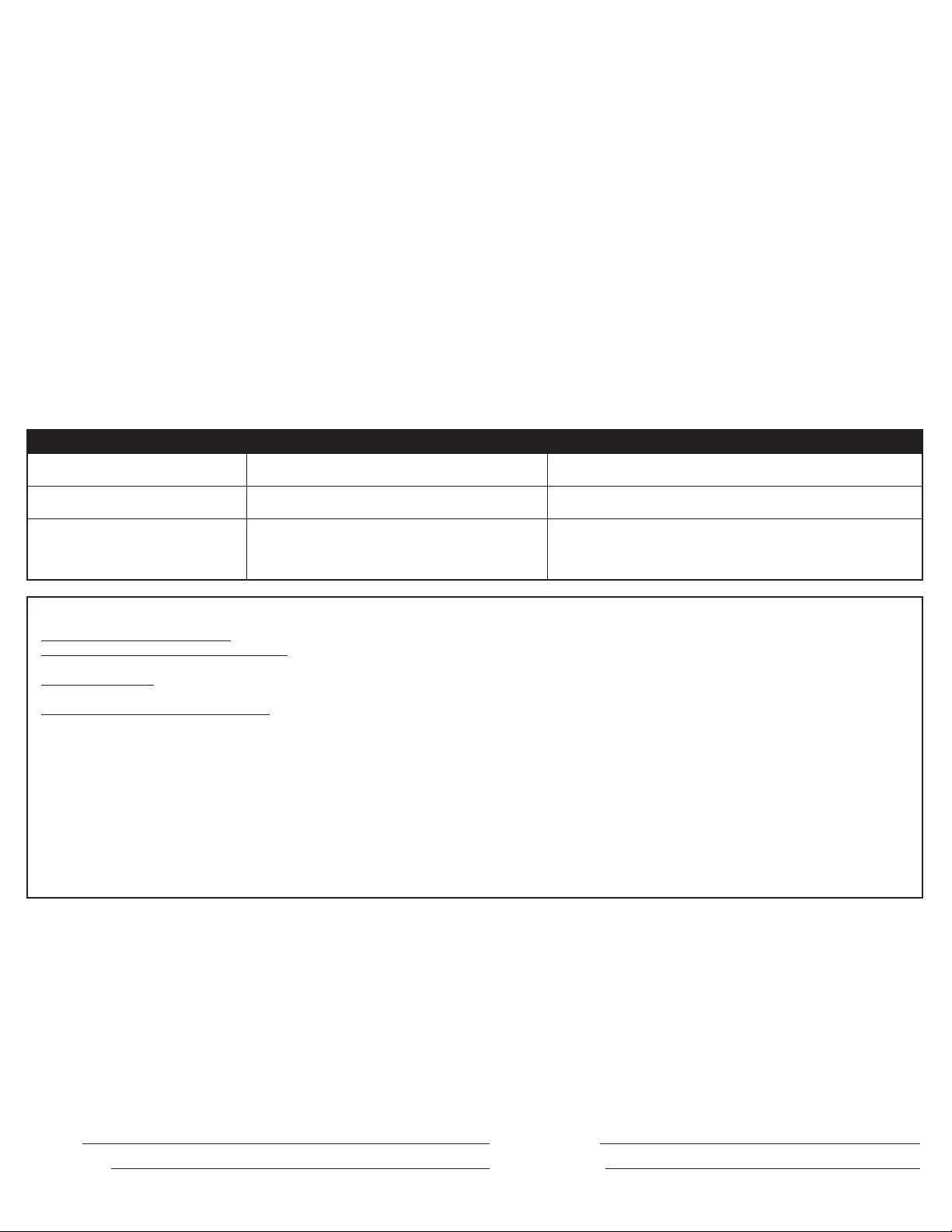
Trouble Cause possible Solution suggérée
1. La hotte ne fonctionne pas lorsque 1a. Un fusible peut être grillé ou un disjoncteur peut être déclenché. 1a. Remplacer le fusible ou réinitialiser le disjoncteur.
l’interrupteur est à EN (ON). 1b. Le câblage n’est pas raccordé correctement. 1b. Couper l’alimentation de l’unité. Vérifier que tous les fils sont raccordés.
2. La hotte fonctionne, mais l’air circule plus 2. Obstruction dans les conduits d’évacuation. 2. Vérifier pour quelque obstruction dans les conduits incluant le filtre.
lentement que la normale.
3. La hotte produit un son de crécelle. 3a. Les filtres sont lâches 3a. Couper l’alimentation à l’unité. Vérifier que tous les filtres sont bien fixés.
3b. Le raccord des conduits est lâche. 3b. Couper l’alimentation de l’unité. Vérifier que tous les raccords des
conduits sont bien serrés.
3c. Le clapet est coincé 3c. Coupez le courant à l’unité. Vérifiez que le clapet s’ouvre librement.
CE QUE COUVRE CETTE GARANTIE : Ce produit est garanti contre tout vice de fabrication ou de matière.
COMBIEN DE TEMPS CETTE GARANTIE DURE : Cette garantie se rapporte seulement à l'acheteur original du produit et dure pendant une (1) année de la date de
l'achat original ou jusqu'à ce que l'acheteur original du produit vend ou transfère le produit, celui qui se produit en premier.
QUE FERA AIR KING : Au cours de la période de garantie, Air King, à son choix, réparera ou remplacera n'importe quelle partie ou pièces qui s'avèrent défectueuses ou
remplacera le produit entier par le même modèle ou un modèle comparable.
CE QUE CETTE GARANTIE NE COUVRE PAS : Cette garantie ne s'applique pas si le produit était endommagé ou arrête de fonctionner en raison d’un accident, d’une
mauvaise manipulation ou opération, de dommages d’expédition, d’abus, de mauvaise utilisation, de réparation faite ou tentées non autorisées. Cette garantie ne couvre
pas les coûts d'expédition pour le retour des produits à Air King pour la réparation ou le remplacement. Air King payera les frais d'expédition de retour de Air King après les
réparations ou le remplacement de garantie.
TOUTES LES GARANTIES, EXPRESSES OU TACITES (COMPRENANT, SANS LIMITATION, TOUTE GARANTIE TACITE DE VALEUR MARCHANDE), DURENT UN AN DE LA
DATE DE L'ACHAT ORIGINAL OU JUSQU'À CE QUE L'ACHETEUR ORIGINAL DU PRODUIT VEND OU TRANSFÈRE LE PRODUIT, CELUI QUI SE PRODUIT EN PREMIER ET
DANS AUCUN CAS AIR KING N’ASSUME AUCUNE RESPONSABILITÉ EXPRESSE OU TACITE POUR (I) DES DOMMAGES ACCIDENTELS OU INDIRECTS DE N’IMPORTE
QUELLE CAUSE, OU (II) LE REPLACEMENT OU LA RÉPARATION DE TOUS FUSIBLES, DISJONCTEURS OU RÉCEPTACLES DE MAISON. MALGRÉ N'IMPORTE QUOI À
L'EFFET CONTRAIRE, DANS AUCUN CAS LA RESPONSABILITÉ D’AIR KING, SOUS UNE GARANTIE EXPRESSE OU TACITE, NE DÉPASSERA LE PRIX D'ACHAT DU PRODUIT
ET UNE TELLE RESPONSABILITÉ SE TERMINERA AVEC L'EXPIRATION DE LA PÉRIODE DE GARANTIE.
Certains états et provinces ne permettent pas les limitations de la période de garantie, ou l'exclusion ou la restriction des dommages accidentels ou indirects, et, par
conséquent, les présentes restrictions ne peuvent pas s’appliquer. La présente garantie vous donne des droits légaux spécifiques et peut-être certains autres droits qui
peuvent varier selon la province. La preuve d’achat est exigée avant qu'une réclamation de garantie ne soit acceptée.
SERVICE À LA CLIENTÈLE :
GARANTIE LIMITÉE
Notre équipe de service à la clientèle est disponible pour vous aider avec des questions sur le produit, les adresses des centres de service, et les pièces de rechange.
Vous pouvez la rejoindre, du lundi au vendredi, de 8h:00 à 16h:00 HNE. Veuillez avoir le numéro du modèle disponible, ainsi que le genre et le style (qui se trouvent sur
l'étiquette à l'intérieur de votre produit). Veuillez ne pas renvoyer le produit à l'endroit de l'achat.
IL SE PEUT QUE LES PIÈCES POUR LES PRODUITS DISCONTINUÉS, OBSOLÈTES ET AUTRES PRODUITS NE SOIENT PAS DISPONIBLES. POUR DES RAISONS
DE SÛRETÉ, BEAUCOUP DE COMPOSANTS ÉLECTRONIQUES ET LA PLUPART DES COMPOSANTS DES CHAUFFAGES NE SONT PAS À LA DISPOSITION DES
CONSOMMATEURS POUR L'INSTALLATION OU LE REMPLACEMENT.
Sans frais (800) 465-7300
www.airkinglimited.com
Installateur : Date d’installation :
Endroit de l’achat : Numéro de modèle :
6728024M Rev. C 4-12 10 of 12
www.airkinglimited.com
Page 11
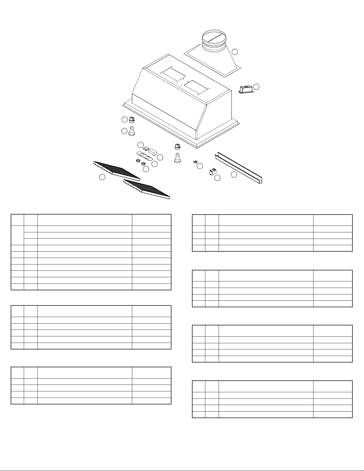
TABLEAU DES PIÈCES DE RECHANGE
1
2
9
10
3
4
5
6
11
7
12
8
TOUS LES MODÈLES LIN
# de pièce
# Qté. Description de remplacement
1 1 Adaptateur de sortie vertical (300, 500, 600 PCM) 5S1136141
1 Adaptateur de sortie vertical (900 PCM) 5S1136142
1 Adaptateur de sortie vertical (1200 PCM) 5S1136143
2 1 Boîte de filage 5S1136064
3 1 Interrupteur du moteur 5S1136070
4 1 Interrupteur du lampe 5S1141013
5 1 Plaque d’interrupteur 5S1142010
6 2 Bouton 5S1142011
7 1 Thermostat 5S1141012
8 1 Relais 5S1239008
MODÈLES LIN24
# de pièce
# Qté. Description de remplacement
9 2 Douille 5S1136075
10 2 Lampe PAR16 de 45W 5S1136099
11 3 Filtre déflecteur - PHGB1 5S1136077
12 1 Dalot à graisse 5S1141320
2 Filtre d'entretoise 5S1141221
MODÈLES LIN28
# de pièce
# Qté. Description de remplacement
9 2 Douille 5S1136075
10 2 Lampe PAR16 de 45W 5S1136099
11 2 Filtre déflecteur - PHGB2 5S1136078
12 1 Dalot à graisse 5S1141370
MODÈLES LIN34
# de pièce
# Qté. Description de remplacement
9 2 Douille 5S1136075
10 2 Lampe PAR16 de 45W 5S1136099
11 2 Filtre déflecteur - PHGB3 5S1136079
12 1 Dalot à graisse 5S1136135
MODÈLES LIN40
# de pièce
# Qté. Description de remplacement
9 2 Douille 5S1136075
10 2 Lampe PAR16 de 45W 5S1136099
11 2 Filtre déflecteur - PHGB3 5S1136079
12 1 Dalot à graisse 5S1136135
MODÈLES LIN46
# de pièce
# Qté. Description de remplacement
9 2 Douille 5S1136075
10 2 Lampe PAR16 de 45W 5S1136099
11 3 Filtre déflecteur - PHGB3 5S1136079
12 1 Dalot à graisse 5S1136139
MODÈLES LIN58
# de pièce
# Qté. Description de remplacement
9 3 Douille 5S1136075
10 3 Lampe PAR16 de 45W 5S1136099
11 3 Filtre déflecteur - PHGB3 5S1136079
12 1 Dalot à graisse 5S1136139
6728024M Rev. C 4-12 11 of 12
www.airkinglimited.com
Page 12

REMARQUES
6728024M Rev. C 4-12 12 of 12
www.airkinglimited.com
 Loading...