

Page 1

IMPORTANT INSTRUCTIONS -
OPERATING MANUAL
Models: ES80S, ES130S,
ES80D, ES130D
Exhaust Fan
READ AND SAVE THESE INSTRUCTIONS
READ CAREFULLY BEFORE ATTEMPTING TO ASSEMBLE, INSTALL, OPERATE OR MAINTAIN THE PRODUCT DESCRIBED.
PROTECT YOURSELF AND OTHERS BY OBSERVING ALL SAFETY INFORMATION. FAILURE TO COMPLY WITH
INSTRUCTIONS COULD RESULT IN PERSONAL INJURY AND/OR PROPERTY DAMAGE!
RETAIN INSTRUCTIONS FOR FUTURE REFERENCE.
GENERAL SAFETY INFORMATION
When using electrical appliances, basic precautions
should always be followed to reduce the risk of fire,
electric shock and injury to person, including the following:
WARNING: TO REDUCE THE RISK OF FIRE, ELECTRIC
SHOCK AND INJURY TO PERSON, OBSERVE THE FOLLOWING:
a) Use this unit only in the manner intended by the manufacturer.
If you have questions, contact the manufacturer.
b) Before servicing or cleaning the unit, switch power off at
service panel and lock the service disconnecting means to
prevent power from being switched on accidentally. When
the service disconnecting means cannot be locked, securely
fasten a prominent warning device, such as a tag, to the
service panel.
WARNING: TO REDUCE THE RISK OF FIRE, ELECTRIC
SHOCK AND INJURY TO PERSON, OBSERVE THE FOLLOWING:
a) Installation work and electrical wiring must be done by
qualified person(s) in accordance with all applicable codes
and standards, including fire-related construction.
d) Ducted fans must always be vented to the outdoors.
e) If this unit is to be installed over a tub or shower, it must be
marked as appropriate for the application and be connected
to a GFCI (Ground Fault Circuit Interrupter) - protected branch
circuit.
f) This unit must be grounded.
g) To avoid motor bearing damage and noisy and/or unbalanced
impellers, keep drywall spray, construction dust, etc. off
power unit.
h) NEVER place a switch where it can be reached from a tub
or shower.
i) Suitable for use with electronic speed control device.
j) Do not install into ceilings thermally insulated to a value
greater than R40.
b) Sufficient air is needed for proper combustion and exhausting
of gases through the flue (chimney) of fuel burning equipment
to prevent back drafting. Follow the heating equipment
manufacturer’s guideline and safety standards such as those
published by the National Fire Protection Association (NFPA)
and the American Society for Heating, Refrigeration, and Air
Conditioning Engineers (ASHRAE), and the local code authorities.
c) When cutting or drilling into wall or ceiling, do not damage
electrical wiring and other hidden utilities.
CAUTION: FOR GENERAL VENTILATING USE ONLY. DO
NOT USE TO EXHAUST HAZARDOUS OR EXPLOSIVE MATERIALS
AND VAPORS.
WARNING: DO NOT USE IN KITCHENS.
k) Read all instructions before installing or using exhaust fan.
SAVE THESE INSTRUCTIONS
A210572218 Rev. C 4-11 1 of 12
www.airkinglimited.com
Page 2
INSTALLATION INSTRUCTIONS
CAUTION:
PANEL BEFORE STARTING INSTALLATION.
MAKE SURE POWER IS SWITCHED OFF AT SERVICE
SECTION 1
Preparing the Exhaust Fan
1. Unpack fan from the carton and confirm that all pieces are present.
In addition to the exhaust fan you should have:
1 - Grill
1 - Damper Assembly (attached)
4 - Mounting Rails
1 - Instruction/Safety Sheet
2. Choose the location for your fan. To ensure the best air and sound
performance, it is recommended that the length of ducting and the
number of elbows be kept to a minimum, and that insulated hard
ducting be used. Larger duct sizes will
reduce noise and airflow restrictions.
This fan will require at least 10" of
clearance in the ceiling or wall, and will
mount through drywall up to 3/4" thick.
3. Select the most convenient electrical
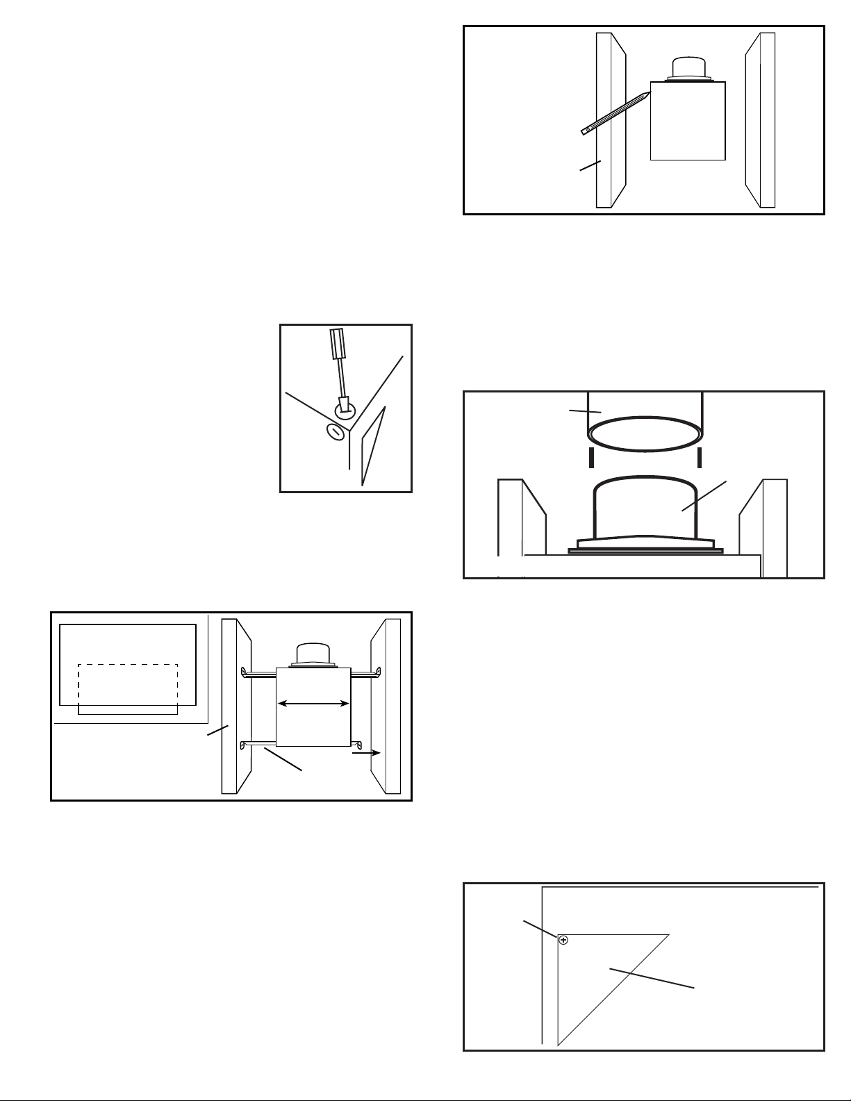
knockout and remove using a straightblade screw driver (Figure 1).
Figure 1
Joist
Figure 3
SECTION 4
Ducting
CAUTION: ALL DUCTING MUST COMPLY WITH LOCAL AND
NATIONAL BUILDING CODES.
1. Connect the ducting to the fan’s duct collar (Figure 4). Secure
in place using tape or screw clamp. Always duct the fan to the
outside through a wall or roof cap.
Ducting
Duct
Collar
SECTION 2
New Construction
1. Install the rails on the housing and position the housing next to the
joist. Line up housing so that it will be flush with the finished ceiling.
Secure the ends of the rails with screws or nails (not included) to
the joists and slide the housing into the final position (Figure 2).
Housing
Joist
Figure 2
Mounting Rails
SECTION 3
Existing Construction
1. Set housing in position between the joist and trace an outline onto
the ceiling material (Figure 3). Set housing aside and cut opening,
being careful not to cut or damage any electrical or other hidden
utilities. Install the rails on the housing and position the housing in
the previously cut hole so that it is flush with the finished ceiling.
Secure the ends of the rails to the joists (Figure 3).
Figure 4
SECTION 5
Wiring
CAUTION: MAKE SURE POWER IS SWITCHED OFF AT SERVICE
PANEL BEFORE STARTING INSTALLATION.
CAUTION: ALL ELECTRICAL CONNECTIONS MUST BE MADE
IN ACCORDANCE WITH LOCAL CODES, ORDINANCES, OR NATIONAL
ELECTRICAL CODE. IF YOU ARE UNFAMILIAR WITH METHODS OF
INSTALLING ELECTRICAL WIRING, SECURE THE SERVICES OF A
QUALIFIED ELECTRICIAN.
NOTE: This unit includes a side access panel for wiring that does not
require the removal of the fan’s blower assembly. If you choose to wire
the unit from the inside, you will need to remove the blower assembly
and internal wiring compartment. Both methods are equally effective.
1a. External Wire Compartment: Remove the wire compartment
cover screw and place cover in a secure place (Figure 5).
Screw
Wire
Compartment
Cover
Figure 5
A210572218 Rev. C 4-11 2 of 12
www.airkinglimited.com
Page 3
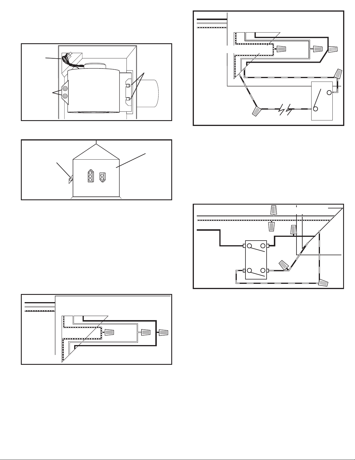
1b. Internal Wire Compartment: Using a 7/16" socket, remove the
two hex nuts holding the blower assembly in place. Lift up on the
assembly and slide it out of the tabs on the housing (Figure 6).
Remove the wire compartment cover screw and place the cover
in a secure place (Figure 7).
Plug
Tabs
Supply from
house
Ground (Green or Bare)
Hot (Black)
Neutral
(White)
Black
Yellow
Hex Nuts
Figure 6
NOTE: If the fan motor plug is connected to the fan housing receptacle,
unplug so the blower assembly can be completely removed.
Wire Compartment
Cover
Screw
Figure 7
SINGLE SPEED UNITS (models ES80S and ES130S)
2a. Run wiring from an approved wall switch (not included) carrying
the appropriate rating. One neutral (white), one ground (green or
bare copper), and one hot (black lead connected to the switch).
Secure the electrical wires to the housing with an approved
electrical connector. Make sure you leave enough wiring in the
box to make the connection to the fan’s receptacle.
2b. From where you have chosen to access the fan’s junction box,
connect the white wire from the house to the white wire from the
fan’s receptacle. Connect the black wire from the wall switch to
the black wire from the fan’s receptacle. Connect the ground wire
from the house to the green wire from the fan housing (Figure 8).
Use approved methods for all connections.
Supply from
house
Yellow
Switch
Figure 9
3b. Intermittent Ventilation: For two speed fans wired for intermittent
ventilation with a standard duplex toggle switch (such as Leviton
5224-2W not included). Connect the White wire of the fan to the
White (Neutral) wire from the power source. Connect the ground
wire from the fan to the ground wire from the power source.
Properly ground the switches. Connect the black wire from the
supply to one side of the top switch. Connect the black wire
from the fan to the other side of the top switch, Connect 1 yellow
wire from the fan to each side of the bottom switch. The top
switch turns the fan On & Off, the bottom switch changes speed
between high and low (Figure 10).
Supply from house
Neutral (White)
Ground (Green or Bare)
Hot
(Black)
Switch
Black
Fan
Yellow
Yellow
Figure 9
NOTE: The fan’s receptacle wires might need to be pulled outside
compartment for connection. Only pull the five loose wires outside of
compartment. Additional wires will be present.
NOTE: Unit must be grounded according to all local and national codes.
Ground
White
4. Carefully tuck wire back inside wire compartment and replace
wire compartment cover securing with the screw that was
removed earlier.
Hot (Black)
Figure 8
TWO SPEED UNITS (models ES80D and ES130D)
3a. Continuous Ventilation: For two speed fans wired for continuous
ventilation, connect the White wire of the fan to the White (Neutral) wire from the power source. Connect the ground wire from
the house to the green wire from the fan housing. Run 2 wires
from a properly grounded wall switch (not included) to the fan.
Connect the Black wire of the fan to the Black wire (Hot) from the
power source. Connect the Hot Yellow wire from the fan to the
input of the switch. Connect the second Yellow wire from the fan
to the output side of the switch. Closing the switch will change
from normal to high speed (Figure 9).
A210572218 Rev. C 4-11 3 of 12
www.airkinglimited.com
SECTION 6
Completing the Installation
1. If the fan’s blower assembly was removed during the wiring
process, reinstall the blower by reversing the directions in Section
4 (Wiring), Step 1b.
SINGE SPEED UNITS (models ES80S and ES130S)
2. Plug the fan’s 2 pin quick connect motor cord into the receptacle
located on the side of the wire compartment cover. Plug the 3 pin
Page 4
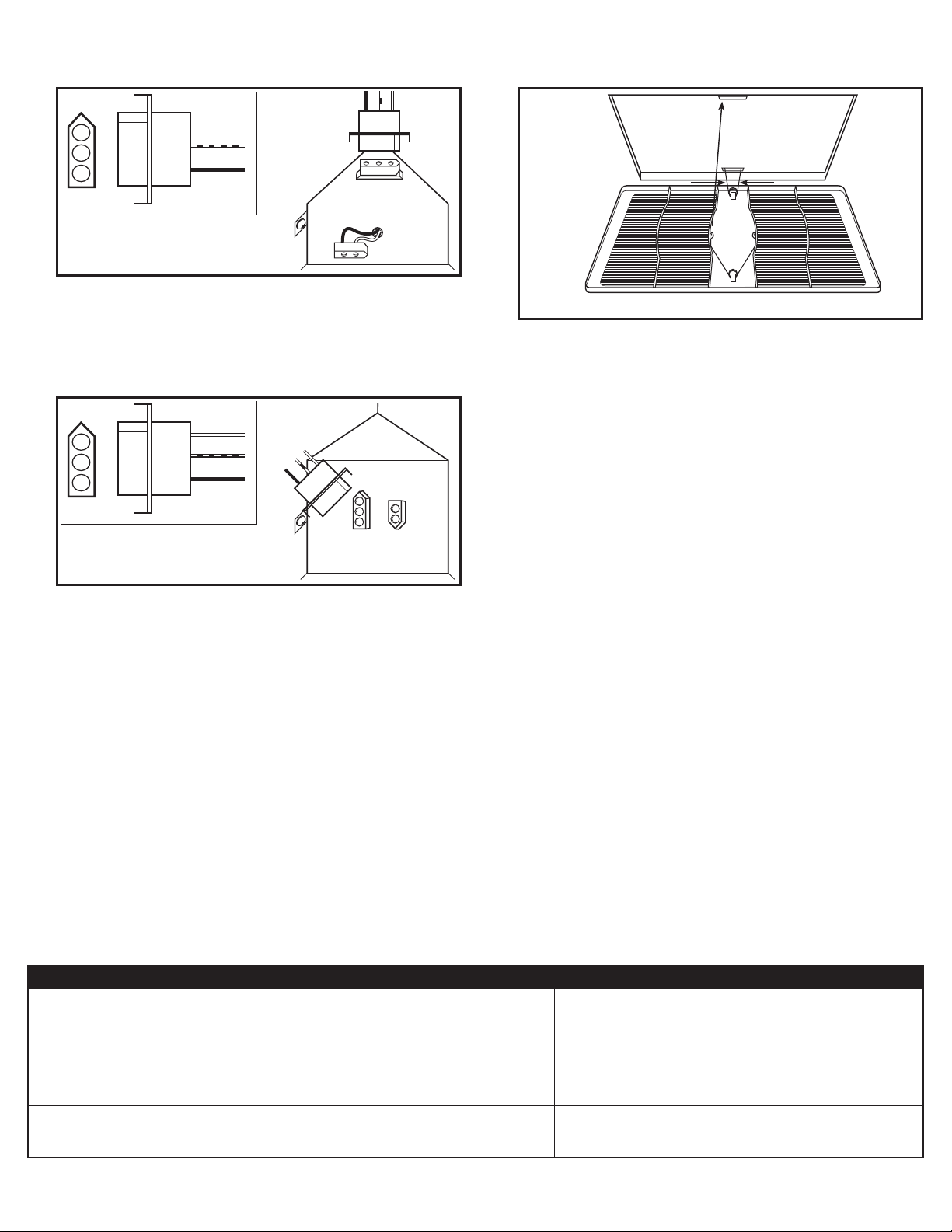
quick connect motor cord into the receptacle located on the top
of the wire compartment cover These cords will only fit one way
into the receptacles (Figure 11).
Figure 11
4. Install the grill by squeezing the two ends of the springs together
and installing them up into the slots on the fan’s housing. Push
the grill up into position (Figure 13).
TWO SPEED UNITS (models ES80D and ES130D)
3. Plug the fan’s 2 pin quick connect motor cord and the 3 pin quick
connect motor cord into the receptacles located on the top of the
wire compartment cover. These cords will only fit one way into
the receptacles (Figure 12).
Figure 12
Figure 13
5. Restore power and test your installation.
SECTION 7
Use and Care
CAUTION: MAKE SURE POWER IS SWITCHED OFF AT SERVICE
PANEL BEFORE SERVICING THE UNIT.
1. Cleaning the Grill: Remove grill and use a mild detergent, such
as dishwashing liquid, and dry with a soft cloth. NEVER USE ANY
ABRASIVE PADS OR SCOURING POWDERS. Completely dry grill
before reinstalling. Refer to instructions in Section 5 Finishing the
Installation, to reinstall grill.
2. Cleaning the Fan Assembly: Wipe all parts with a dry cloth or gently
vacuum the fan. NEVER IMMERSE ELECTRICAL PARTS IN WATER.
Troubleshooting Guide
Trouble Probable Cause Suggested Remedy
1. Fan does not operate when the switch is on. 1a. A fuse may be blown or a circuit tripped. 1a. Replace fuse or reset circuit breaker.
1b. Connector plug from motor is not plugged in. 1b. Turn off power to unit. Remove Grill and plug motor into receptacle
in housing. Restore power to unit.
1c. Wiring is not connected properly. 1c. Turn off power to unit. Check that all wires are connected.
1d Motor has stopped operating. 1d. Replace motor.
2. Fan is operating, but air moves slower than normal. 2. Obstruction in the exhaust ducting. 2. Check for any obstructions in the ducting. The most common are bird
nests in the roof cap or wall cap where the fan exhausts to the outside.
3. Fan is operating louder than normal 3a. Motor is loose. 3a. Turn off power to unit. Remove grill and check that all screws are fully
tightened. Restore power to unit.
3b. Fan blade is hitting housing of unit. 3b. Call your dealer for service.
A210572218 Rev. C 4-11 4 of 12
www.airkinglimited.com
Page 5
LIMITED WARRANTY
WHAT THIS WARRANTY COVERS: This product is warranted against defects in workmanship and/or materials.
HOW LONG THIS WARRANTY LASTS: This warranty extends only to the original purchaser of the product and lasts for five (5) years from the date of origi-
nal purchase or until the original purchaser of the product sells or transfers the product, whichever first occurs.
WHAT AIR KING WILL DO: During the warranty period, Air King will, at its sole option, repair or replace any part or parts that prove to be defective or
replace the whole product with the same or comparable model.
WHAT THIS WARRANTY DOES NOT COVER: This warranty does not apply if the product was damaged or failed because of accident, improper handling or
operation, shipping damage, abuse, misuse, unauthorized repairs made or attempted. This warranty does not cover shipping costs for the return of products
to Air King for repair or replacement. Air King will pay return shipping charges from Air King following warranty repairs or replacement
ANY AND ALL WARRANTIES, EXPRESSED OR IMPLIED (INCLUDING, WITHOUT LIMITATION, ANY IMPLIED WARRANTY OF MERCHANTABILITY), LAST
ONE YEAR FROM THE DATE OF ORIGINAL PURCHASE OR UNTIL THE ORIGINAL PURCHASER OF THE PRODUCT SELLS OR TRANSFERS THE PRODUCT,
WHICHEVER FIRST OCCURS AND IN NO EVENT SHALL AIR KING’S LIABILITY UNDER ANY EXPRESS OR IMPLIED WARRANTY INCLUDE (I) INCIDENTAL OR
CONSEQUENTIAL DAMAGES FROM ANY CAUSE WHATSOEVER, OR (II) REPLACMENT OR REPAIR OF ANY HOUSE FUSES, CIRCUIT BREAKERS OR RECEPTACLES.
NOTWITHSTANDING ANYTHING TO THE CONTRARY, IN NO EVENT SHALL AIR KING’S LIABILITY UNDER ANY EXPRESS OR IMPLIED WARRANTY EXCEED
THE PURCHASE PRICE OF THE PRODUCT AND ANY SUCH LIABILITY SHALL TERMINATE UPON THE EXPIRATION OF THE WARRANTY PERIOD.
Some states and provinces do not allow limitations on how long an implied warranty lasts, or the exclusion or limitation of incidental or consequential damages,
so these exclusions or limitations may not apply to you. This warranty gives you specific legal rights. You may also have other rights which vary from state to
state and province to province. Proof of purchase is required before a warranty claim will be accepted.
CUSTOMER SERVICE:
Our Customer Service team is available to assist you with product questions, service center locations, and replacement parts. They can be reached Monday
through Friday, 8am-4pm Eastern. Please have your model number available, as well as the type and style (located on the label inside of your product).
Please do not return product to place of purchase.
PARTS FOR DISCONTINUED, OBSOLETE AND CERTAIN OTHER PRODUCTS MAY NOT BE AVAILABLE. DUE TO SAFETY REASONS, MANY ELECTRONIC
COMPONENTS AND MOST HEATER COMPONENTS ARE NOT AVAILABLE TO CONSUMERS FOR INSTALLATION OR REPLACEMENT.
Toll-Free (800) 465-7300
www.airkinglimited.com
Installer: Installation Date:
Place of Purchase: Model Number:
A210572218 Rev. C 4-11 5 of 12
www.airkinglimited.com
Page 6
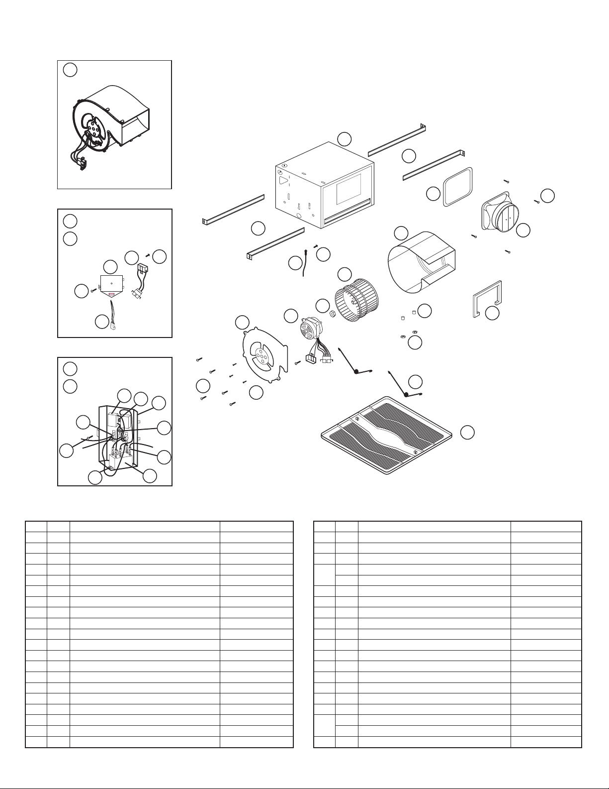
3 Blower Assembly
Includes Components 8, 9, 10,
11, 12, 13 & 14 Assembled.
20
ES80S
21
ES130S
B
A
D
E
REPLACEMENT PARTS DIAGRAM
1
2
6
2
C
19
20
8
9
12
10
11
18
25
5
4
ES80D
22
ES130D
23
G
F
# Qty. Description Replacement Part #
1 1 Fan Housing 5S1239009
2 4 Mounting Rails 5S1299002
3 1 Blower Assembly 5S2239008
4 1 6” Metal Collar Assembly 5S5299100
5 4 Screws 5S1999010
6 1 Collar Gasket 5S1202054
7 1 Outlet Gasket 5S1202053
8 1 Blower Housing 5S2202022
9 1 Blower Wheel 5S2202023
10 1 Hex Nuts 5S2202014
11 1 Motor 5S2239001
12 1 Motor Plate 5S2202020
13 3 Motor Mount Screws 5S2202027
14 6 Plate Mount Screws 5S2202017
15 1 Grill 5S1202048
16 2 Grill Springs 5S1202046
17 2 Flange Nut 5S1202031
18 2 Grommets 5S1202032
19 1 #10 Ground Screw 5S1999002
20 1 14 ga Ground Wire 5S1999003
H
I
A
B
C
E
D
14
13
17
16
15
# Qty. Description Replacement Part #
21 1 Wire Compartment Assembly - ES80S 5S1239001
22 1 Wire Compartment Assembly - ES130S 5S1239002
A 1 Wire Compartment 5S1239003
B 1 Capacitor Harness - ES80S 5S2239002
1 Capacitor Harness - ES130S 5S2239003
C 1 Capacitor Mount Screw 5S1202049
D 1 Wire Cover Screw 5S1202049
E 1 Power Harness 5S2239004
23 1 Wire Compartment Assembly - ES80D 5S1239004
24 1 Wire Compartment Assembly - ES130D 5S1239005
A 1 Wire Compartment 5S1239006
B 1 #10 Ground Screw 5S1999002
C 1 ESD Jumper Wire 5S1239007
D 1 SPDT 120 Volt Relay 5S1239008
E 2 Relay Mount Screw 5S1202049
F 1 Wire Cover Screw 5S1202049
G 1 Power Harness 5S2239005
H 1 2 Speed Cap Harness - ES80D 5S2239006
1 2 Speed Cap Harness - ES130D 5S2239007
I 1 Capacitor Mount Screw 5S1202049
A210572218 Rev. C 4-11 6 of 12
www.airkinglimited.com
 Loading...