

Page 1

IMPORTANT INSTRUCTIONS -
OPERATING MANUAL
Models: BFQ50, BFQ70, BFQ75, BFQ90,
BFQ110, BFQ140, BFQ175
Exhaust Fan
READ AND SAVE THESE INSTRUCTIONS
READ CAREFULLY BEFORE ATTEMPTING TO ASSEMBLE, INSTALL, OPERATE OR MAINTAIN THE PRODUCT DESCRIBED. PROTECT
1. Read all instructions before installing or using exhaust fan.
2. Use this unit only in the manner intended by the manufacturer.
If you have questions, contact the manufacturer.
3. Before servicing or cleaning the unit, switch power off at
service panel and lock the service disconnecting means to
prevent power from being switched on accidentally. When
the service disconnecting means cannot be locked, securely
fasten a prominent warning device, such as a tag, to the
service panel.
4. Installation work and electrical wiring must be done by
qualified person(s) in accordance with all applicable codes
and standards, including fire-related construction.
5. Sufficient air is needed for proper combustion and exhausting
of gases through the flue (chimney) of fuel burning equipment
to prevent back drafting. Follow the heating equipment
manufacturer’s guideline and safety standards such as those
published by the National Fire Protection Association (NFPA)
and the American Society for Heating, Refrigeration, and Air
Conditioning Engineers (ASHRAE), and the local code authorities.
YOURSELF AND OTHERS BY OBSERVING ALL SAFETY INFORMATION. FAILURE TO COMPLY WITH
INSTRUCTIONS COULD RESULT IN PERSONAL INJURY AND/OR PROPERTY DAMAGE!
RETAIN INSTRUCTIONS FOR FUTURE REFERENCE.
GENERAL SAFETY INFORMATION
When using electrical appliances, basic precautions
should always be followed to reduce the risk of fire,
electric shock and injury to person, including the following:
6. When cutting or drilling into wall or ceiling, do not damage
electrical wiring and other hidden utilities.
7. Ducted fans must always be vented to the outdoors.
8. This unit must be grounded.
9. To avoid motor bearing damage and noisy and/or unbalanced
impellers, keep drywall spray, construction dust, etc. off
power unit.
WARNING: TO REDUCE THE RISK OF FIRE, ELECTRIC SHOCK,
DO NOT USE THIS FAN WITH ANY SOLID-STATE SPEED CONTROL
DEVICE.
10. Acceptable for use over a bathtub or shower when installed
in a GFCI protected branch circuit.
11. NEVER place a switch where it can be reached from a tub or
shower.
WARNING: DO NOT USE IN KITCHENS
CAUTION: FOR GENERAL VENTILATING USE ONLY. DO
NOT USE TO EXHAUST HAZARDOUS OR EXPLOSIVE MATERIALS
AND VAPORS.
SAVE THESE INSTRUCTIONS
2A0572021 Rev. C 6/06
www.airkinglimited.com
1 of 8
Page 2
INSTALLATION INSTRUCTIONS
CAUTION:
SERVICE PANEL BEFORE STARTING INSTALLATION.
MAKE SURE POWER IS SWITCHED OFF AT
SECTION 1
Preparing the Exhaust Fan
1. Unpack fan from the carton and confirm that all pieces are
present. In addition to the exhaust fan you should have:
1 - Grill
1 - Damper Assembly (attached)
1 - Mounting Bracket
1 - Hardware Bag
1 - Electrical Connector
3 - Wire Nuts
1 - Instruction/Safety Sheet
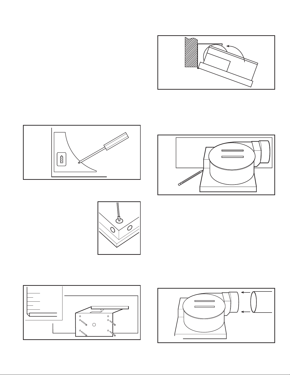
2. Remove the wire compartment cover and store in the carton
until needed so it does not get damaged or lost (Figure 1).
2. Snap the fan body into the bracket (Figure 4). The fan can be
snapped into position with the duct collar facing to the left
or the right depending which is most convenient.
Figure 4
SECTION 3
Existing Construction
1. Position housing against the joist or stud and trace an outline
of the housing onto the ceiling/wall material. Set housing
aside and cut opening, being careful not to cut or damage
any electrical or other hidden utilities (Figure 5).
Figure 1
3. Choose the location for your fan. To ensure the best air and
sound performance, it is recommended that the length of
ducting and the number of elbows be kept to a minimum, and
that insulated hard ducting be used.
Larger duct sizes will reduce noise
and airflow restrictions.
4. Select the most convenient
electrical knockout and remove
using a straight-blade screw driver
(Figure 2).
SECTION 2
New Construction
1. Using the gauge on the mounting bracket, line up the bracket
on the joist so the bottom of the fan will be flush with the
finished ceiling. Nail or screw the bracket in place securely
(Figure 3).
"
3/4
"
1/2
Figure 2
Figure 5
2. Line up the bracket on the joist so the bottom of the fan will
be flush with the finished ceiling. Nail or screw the snap-in
bracket in place securely (Figure 3).
3. Snap the fan body into the bracket (Figure 4). The fan can be
snapped into position with the duct collar facing to the left
or the right depending which is most convenient.
SECTION 4
Ducting
CAUTION: ALL DUCTING MUST COMPLY WITH LOCAL
AND NATIONAL BUILDING CODES.
1. Connect the ducting to the fan’s duct collar (Figure 6). Secure
in place using tape or screw clamp. Always duct the fan to
the outside through a wall or roof cap.
Figure 3
2A0572021 Rev. C 6/06 2 of 8
www.airkinglimited.com
Figure 6
Page 3
SECTION 5
Wiring
CAUTION: MAKE SURE POWER IS SWITCHED OFF AT
SERVICE PANEL BEFORE STARTING INSTALLATION.
CAUTION: ALL ELECTRICAL CONNECTIONS MUST BE
MADE IN ACCORDANCE WITH LOCAL CODES, ORDINANCES,
OR NATIONAL ELECTRICAL CODE. IF YOU ARE UNFAMILIAR
WITH METHODS OF INSTALLING ELECTRICAL WIRING, SECURE
THE SERVICES OF A QUALIFIED ELECTRICIAN.
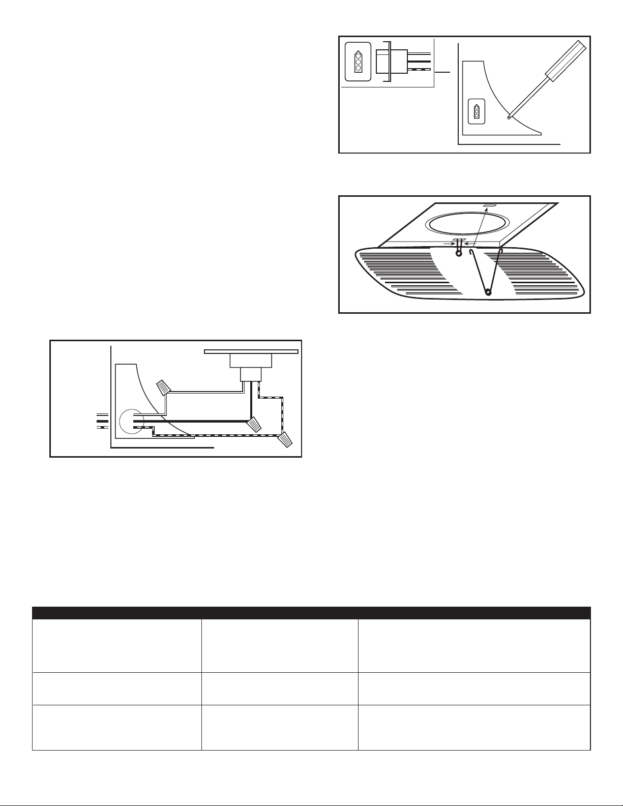
1. Run wiring from an approved wall switch carrying the
appropriate rating. One neutral (white), one ground (green or
bare copper), and one hot (black lead connected to the switch).
Secure the electrical wires to the housing with an approved
electrical connector. Make sure you leave enough wiring in
the box to make the connection to the fan’s receptacle.
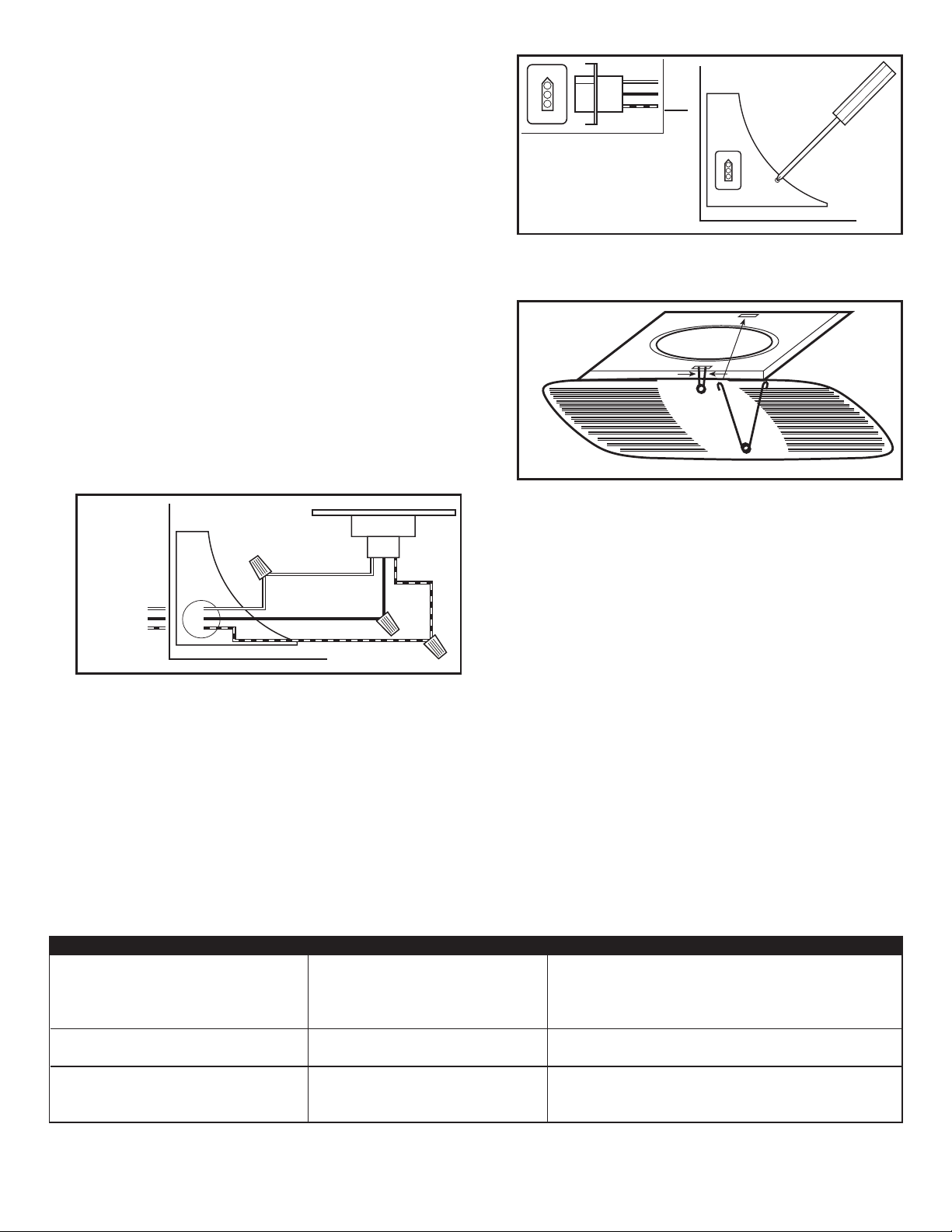
2. From where you have access to inside the fan’s junction
box, connect the White wire from the house to the White
wire from the fan’s receptacle. Connect the Black wire from
the wall switch to the Black wire from the fan’s receptacle.
Connect the ground wire from the house to the Green wire
from the fan’s receptacle (Figure 7). Use approved methods
for all connections.
Figure 8
2. Install the grill by squeezing the two ends of the springs
together and installing them up into the slots of the fan’s
housing. Push the grill up into position (Figure 9).
Figure 9
3. Restore power and test your installation.
SECTION 7
White
Supply
from
Hot (Black)
house
Figure 7
Ground
SECTION 6
Completing the Installation
1. Reinstall the fan’s wire compartment cover. Rotate the blower
wheel by hand to ensure it spins freely. Plug the fan’s quick
connect motor cord into the receptacle. This cord will only
fit one way into the receptacle (Figure 8).
Troubleshooting Guide
Trouble Probable Cause Suggested Remedy
1. Fan does not operate when the switch is on. 1a. A fuse may be blown or a circuit tripped. 1a. Replace fuse or reset circuit breaker.
1b. Connector plug from motor is not plugged in. 1b. Turn off power to unit. Remove Grill and plug motor into receptacle
1c. Wiring is not connected properly. 1c. Turn off power to unit. Check that all wires are connected.
2. Fan is operating, but air moves slower than normal. 2. Obstruction in the exhaust ducting. 2. Check for any obstructions in the ducting. The most common are bird nests
3. Fan is operating louder than normal. 3a. Motor is loose. 3a. Turn off power to unit. Remove grill and check that all screws are fully
3b. Fan blade is hitting housing of unit. 3b. Call your dealer for service.
Use and Care
CAUTION: MAKE SURE POWER IS SWITCHED OFF AT
SERVICE PANEL BEFORE SERVICING THE UNIT.
1. Cleaning the Grill: Remove grill and use a mild detergent,
such as dishwashing liquid, and dry with a soft cloth. NEVER
USE ANY ABRASIVE PADS OR SCOURING POWDERS.
Completely dry grill before reinstalling. Refer to instructions
in Section 6
2. Cleaning the Fan Assembly: Unplug the motor cord from
receptacle. Wipe all parts with a dry cloth or gently vacuum
the fan. NEVER IMMERSE ELECTRICAL PARTS IN WATER.
Plug the motor cord back in and restore power.
Finishing the Installation
in housing. Restore power to unit.
in the roof cap or wall cap where the fan exhausts to the outside.
tightened. Restore power to unit.
, to reinstall grill.
2A0572021 Rev. C 6/06 3 of 8
www.airkinglimited.com
Page 4
LIMITED WARRANTY
All products manufactured by Air King Limited are warranted for one year from the date of purchase against defects in workmanship
and/or material. In addition, all ventilating/exhaust fans, heaters, combination fan lights and/or heaters, and range hoods are
guaranteed for five years from the date of purchase against defects in workmanship and/or material.
This warranty does not cover any labor or shipping costs or the cost of replacement components as part of routine maintenance
such as: range hood grease filters, charcoal filters or combination charcoal/grease filters; replacement light bulbs in range hoods
or bathroom fan/light/bulb heater combinations. As well, any damage or failure caused by abuse, misuse, abnormal usage, faulty
installation, or improper maintenance will not be covered by this warranty.
In order to make a claim on this warranty, you must be the original consumer of the product. You will be required to present to Air
King the original bill of sale showing: date of purchase, place of purchase and model purchased. Failure to meet these requirements
will void your warranty.
Air King will not be held responsible for any bodily injury or damages to personal property or real estate whether caused directly or
indirectly by the product. Some states and provinces do not allow the exclusion or limitation of incidental or consequential damages
and some states do not allow limitations on how long an implied warranty lasts, so these exclusions or limitations may not apply to
you. This warranty gives you specific legal rights and you may have other rights which vary from state to state and province to province.
FOR PARTS OR TECHNICAL ASSISTANCE
Please call: 1-800-465-7300, MONDAY THROUGH FRIDAY, BETWEEN THE HOURS OF 8 AM AND 4:00 PM EST.
PLEASE DO NOT RETURN PRODUCT TO PLACE OF PURCHASE.
Reference the type and style of product (located on label inside of the product) when you call.
For more information please visit our website: wwwairkinglimited.com
2
14
13
12
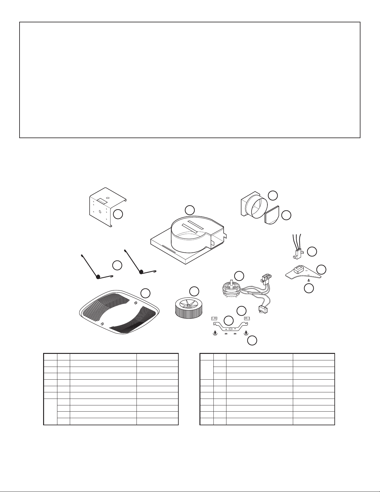
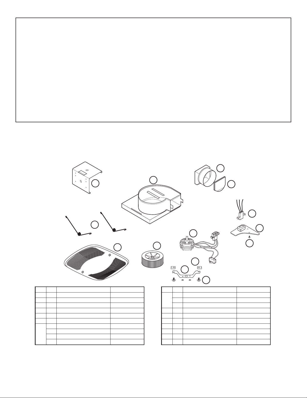
# Qty. Description Replacement Part #
1 1 Fan Housing 5S2205001
2 1 Collar 5S2205002
3 1 Damper 5S2205003
4 1 Polarized Nylon Receptacle 3P 5S2205004
5 1 Wire Cover 5S2205005
6 1 Screw 5S2205006
7 1 Motor - BFQ50 5S2299011
1 Motor - BFQ70 5S2299012
1 Motor - BFQ75 5S2299012
1 Motor - BFQ90 5S2299001
1
3
7
11
8
10
9
# Qty. Description Replacement Part #
7 1 Motor - BFQ110 5S2205008
1 Motor - BFQ140 5S2299002
1 Motor - BFQ175 5S2299013
8 2 Clip 5S2205009
9 2 Screw 5S2205010
10 1 Motor Bracket 5S2299003
11 1 Blower Wheel 5S2299004
12 1 Grill 5S2205011
13 2 Grill Springs 5S2205012
14 1 Snap In Bracket 5S2205013
4
5
6
Installer: _________________________________________________________ Installation Date: _________________________________________
Place of Purchase: _________________________________________________ Model Number: __________________________________________
2A0572021 Rev. C 6/06 4 of 8
www.airkinglimited.com
Page 5

INSTRUCTIONS IMPORTANTES –
MANUEL D’OPÉRATION
Modéles: BFQ50, BFQ70, BFQ75, BFQ90,
BFQ110, BFQ140, BFQ175
Ventilateur d’Évacuation
LIRE ET CONSERVER CES INSTRUCTIONS
LIRE SOIGNEUSEMENT AVANT DE TENTER D’ASSEMBLER, INSTALLER, OPÉRER OU DE RÉPARER LE PRODUIT DÉCRIT. PROTÉGEZ
VOUS-MÊME ET LES AUTRES EN OBSERVANT TOUTE L’INFORMATION DE SÉCURITÉ. FAILLIR À SE CONFORMER AUX
INSTRUCTIONS PEUT RÉSULTER EN BLESSURE PERSONNELLE GRAVE ET/OU EN DOMMAGE À LA PROPRIÉTÉ.
CONSERVER CES INSTRUCTIONS POUR RÉFÉRENCES FUTURES.
INSTRUCTIONS GÉNÉRALES DE SÉCURITÉ
Lors de l’utilisation d’appareils électriques, des précautions de base doivent
toujours être suivies pour réduire les risques d’incendie, de choc
électrique et de blessures corporelles, incluant ce qui suit:
1. Bien lire toutes les instructions avant d’installer ou d’utiliser
le ventilateur d’évacuation.
2. Utiliser cette unité seulement de la manière pour laquelle le
fabricant l’a conçu. Si vous aviez des questions, veuillez
contacter le fabricant.
3. Avant d’effectuer un service ou de nettoyer l’unité, couper
l’alimentation électrique dans le panneau de distribution et
verrouiller le dispositif de déconnexion afin d’éviter que
l’alimentation ne revienne accidentellement. Lorsque le
dispositif ne peut être verrouillé, fixer solidement un avis
d’avertissement, tel qu’une étiquette, au panneau de distribution.
4. Le travail d’installation et le câblage électrique doivent être
effectués par une(des) personne(s) qualifiée(s) en conformité
avec tous les codes et normes applicables, incluant la
construction relative aux incendies.
5. De l’air en quantité suffisante est requis pour la bonne
combustion et l’évacuation de gaz par le conduit (cheminée)
provenant d’équipement de brûlage au combustible pour
prévenir un refoulement. Suivre les directives du fabricant
de l’équipement de chauffage et les normes de sécurité telles
que celles publiées par la National Fire Protection Association
(NFPA) et de la American Society for Heating, Refrigeration,
and Air Conditioning Engineers (ASHRAE), et de celles des
autorités locales du code.
AVERTISSEMENT: POUR USAGE DE VENTILATION
GÉNÉRALE EXCLUSIVEMENT. NE PAS UTILISER POUR ÉVACUER
DU MATÉRIEL ET DES VAPEURS DANGEREUSES OU EXPLOSIVES.
6. Lors de coupe ou de perçage des murs et plafonds, ne pas
endommager le filage électrique et autres utilités cachées.
7. Les ventilateurs avec conduits doivent toujours être évacués
vers l’extérieur.
8. Cette unité doit être mise à la terre.
9. Pour éviter des dommages aux roulements des moteurs et/ou
des hélices bruyantes ou déséquilibrées, empêcher la
poussière de cloison sèche, poussière de construction, etc.,
d’atteindre l’unité de puissance.
AVERTISSEMENT: POUR RÉDUIRE LES RISQUES
D’INCENDIE OU DE CHOC ÉLECTRIQUE, NE PAS UTILISER CE
VENTILATEUR AVEC UN RÉGULATEUR DE VITESSE ÉLECTRONIQUE.
10. Acceptable pour utilisation au-dessus d’une baignoire ou
d’une douche lorsque installé dans un circuit protégé par un
disjoncteur de fuite de terre.
11. NE JAMAIS placer un interrupteur à un endroit qui puisse
être atteint de la baignoire ou de la douche.
AVERTISSEMENT: NE PAS UTILISER DANS LES CUISINES
2A0572021 Rev. C 6/06
CONSERVER CES INSTRUCTIONS
www.airkinglimited.com
5 of 8
Page 6
INSTRUCTIONS D’INSTALLATION
AVERTISSEMENT:
EST COUPÉE AU PANNEAU DE SERVICE AVANT DE COMMENCER
L’INSTALLATION.
VOUS ASSURER QUE L’ALIMENTATION
SECTION 1
Préparation du Ventilateur d’évacuation
1. Sortir le ventilateur de sa boite et confirmer que toutes les
pièces sont présentes. En plus du ventilateur d’évacuation
vous devriez avoir:
1 - Grille
Ensemble de clapet (attaché)
1 1 - Support de Montage
1 - Sac de la Quincaillerie
1 - Connecteur Électrique
3 - Coinceurs à Câbles
Feuillet d’instructions / sécurité
1 -
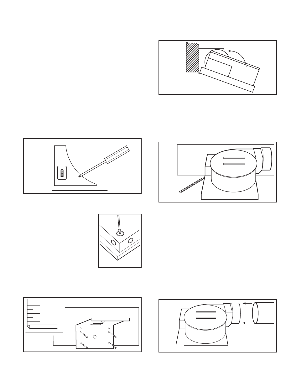
2. Enlever le couvercle du compartiment à câble et le ranger
dans l’emballage jusqu’à ce que vous en ayez besoin afin
qu’il ne soit pas perdu ou endommagé (Figure 1).
2. Fixer par pression le bâti du ventilateur dans le support
(Figure 4). Le ventilateur peut être fixé par pression en position
avec le collet de conduit faisant face à gauche ou à droite
en fonction de quelle direction est la plus pratique.
Figure 4
SECTION 3
Construction Existante
1. Positionner le cabinet contre la solive ou le montant et tracer
le contour du cabinet sur le matériau du mur / plafond. Mettre
le cabinet de côté et découper l’ouverture, en prenant bien
soin de ne pas couper ou endommager d’utilité électrique
ou dissimulée (Figure 5).
Figure 1
3. Choisir l’emplacement pour votre ventilateur. Pour assurer
la meilleure performance d’air et sonore, il est recommandé
que la longueur de conduit et le nombre de coudes soient
gardés au minimum, et que du conduit
rigide isolé soit utilisé. Des conduits
plus gros réduiront le bruit et les
restrictions du débit d’air.
4. Sélectionner l’alvéole défonçable la
mieux appropriée et l’enlever à l’aide
d’un tournevis à lame plate
SECTION 2
Nouvelle construction
1. En utilisant le guide sur le support de montage, aligner le
support sur la solive pour que le dessous du ventilateur soit
à effleurement avec le plafond fini. Clouer ou visser solidement
le support en place (Figure 3).
"
3/4
"
1/2
(Figure 2).
Figure 2
Figure 5
2. Aligner le support sur la solive de manière que le bas du ventilateur
soit à effleurement avec le plafond fini. Clouer ou visser solidement
le support à fixer par pression en place
3.
Fixer par pression le bâti du ventilateur dans le support
(Figure 4). Le ventilateur peut être fixé par pression en position
avec le collet de conduit faisant face à gauche ou à droite
en fonction de quelle direction est la plus pratique.
(Figure 3).
SECTION 4
Conduits
AVERTISSEMENT: TOUS LES CONDUITS DOIVENT ÊTRE
CONFORMES AUX CODES DU BÂTIMENT LOCAUX ET NATIONAUX.
1. Raccorder le conduit au collet de conduit du ventilateur
(Figure 6). Fixer en place à l’aide de ruban ou de serre-joint.
Toujours évacuer le ventilateur vers l’extérieur au travers
de chapeau mural ou de toit.
Figure 3
2A0572021 Rev. C 6/06 6 of 8
www.airkinglimited.com
Figure 6
Page 7
SECTION 5
Câblage
AVERTISSEMENT: VOUS ASSURER QUE L’ALIMENTATION
EST COUPÉE AU PANNEAU DE SERVICE AVANT DE COMMENCER
L’INSTALLATION.
AVERTISSEMENT: TOUTES LES CONNEXIONS DOIVENT
ÊTRE FAITES EN CONFORMITÉ AVEC LES CODES ÉLECTRIQUES
LOCAUX OU NATIONAUX. SI VOUS N’ÊTES PAS FAMILIER AVEC
LES MÉTHODES D’INSTALLATION DE CÂBLAGE ÉLECTRIQUE,
RECOURREZ AUX SERVICES D’UN ÉLECTRICIEN QUALIFIÉ.
1. Courir le filage d’un interrupteur mural approuvé de calibre
approprié. Un fil neutre (blanc), un fil de mise à la terre (vert
ou cuivre dénudé), et un fil vivant (fil noir connecté à
l’interrupteur). Fixer les fils électriques au cabinet à l’aide
d’un connecteur électrique approuvé. Assurez-vous de laisser
suffisamment de fil dans la boite de raccord pour la connexion
au réceptacle du ventilateur.
2. De là où vous avez accès à l’intérieur de la boite de jonction
du ventilateur, connecter le fil Blanc provenant de la résidence
au fil Blanc du réceptacle du ventilateur. Connecter le fil Noir
de l’interrupteur mural au fil Noir du réceptacle du ventilateur.
Connecter le fil de mise à la terre provenant de la résidence
au fil Vert du réceptacle du ventilateur (Figure 7). Utiliser des
méthodes approuvées pour toutes les connexions.
Figure 8
2. Installer la grille en pressant ensemble les deux extrémités
des ressorts et en les installant dans les fentes du châssis
du ventilateur. Pousser la grille en position
(Figure 9).
Figure 9
Restaurer l’alimentation et tester votre installation.
3.
SECTION 7
Utilisation et entretien
Blanc
Fil Chaud (Noir)
la résidence
Alimentation
provenant de
Figure 7
Fil de Masse
SECTION 6
Complétion de l’installation
1. Réinstaller le couvercle du compartiment de câble du ventilateur
en place. Faire tourner la roue de la soufflante à la main pour
vous assurer qu’elle tourne librement. Brancher le cordon à
raccordement rapide dans le réceptacle. Ce cordon ne s’ajuste
que d’une seule façon dans le réceptacle
Trouble Cause Possible Solution Suggérée
1. Le ventilateur ne fonctionne pas lorsque l’interrupteur 1a. Un fusible peut être grillé ou un disjoncteur 1a. Remplacer le fusible ou réinitialiser le disjoncteur.
est à la position en marche. peut être décle.nché.
2. Le ventilateur fonctionne, mais l’air circule plus 2. Obstruction dans les conduits d’évacuation. 2. Vérifier pour toute obstruction dans les conduits. Les plus courantes sont
lentement que la normale. des nids d’oiseau dans le chapeau de toit ou mural là où le ventilateur
3. Le ventilateur fonctionne de manière plus bruyante 3a. Le moteur est lâche. 3a. Couper l’alimentation à l’unité. Retirer la grille et vérifier que toutes les
que la normale. vis sont complètement serrées. Remettre l’alimentation sur l’unité.
(Figure 8).
Guide de dépannage
1b. La fiche de raccord du moteur n’est 1b. Couper l’alimentation à l’unité. Retirer la grille et brancher le moteur dans
pas connectée
1c. Le câblage n’est pas raccordé correctement. 1c. Couper l’alimentation de l’unité. Vérifier que tous les fils sont raccordés.
3b. L’hélice du ventilateur frotte contre le cabinet 3b. Appeler votre marchand pour un service.
de l’unité.
. le réceptacle dans le cabinet. Remettre l’alimentation sur l’unité.
AVERTISSEMENT: VOUS ASSURER QUE L’ALIMENTATION
EST COUPÉE AU PANNEAU DE SERVICE AVANT DE COMMENCER
L’INSTALLATION.
1. Nettoyage de la grille: Retirer la grille et utiliser un détergent
doux, tel que du liquide pour la vaisselle, puis sécher à l’aide
d’un chiffon doux. NE JAMAIS UTILISER D’ABRASIF OU DE
POUDRE À RÉCURER. Sécher complètement la grille avant
de la réinstaller. Pour réinstaller la grille, vous référer à la
Section 6 - Complétion de l’installation.
2. Nettoyage de l’assemblage du ventilateur: Débrancher le cordon
du moteur de son réceptacle. Nettoyer toutes les pièces avec
un chiffon sec ou passer délicatement l’aspirateur dans le
ventilateur. NE JAMAIS IMMERGER DES PIÈCES ÉLECTRIQUES
DANS L’EAU. Rebrancher le cordon et remettre l’alimentation.
s’évacue vers l’extérieur.
2A0572021 Rev. C 6/06 7 of 8
www.airkinglimited.com
Page 8
GARANTIE LIMITÉE
Tous les produits fabriqués par Air King Limited sont garantis pour un an à partir de la date d’achat contre les défauts de main d’œuvre
et/ou de matériel. De plus, tous les ventilateurs / évacuateurs, chaufferettes, combinés ventilateur/ lumière et/ou les chaufferettes et
les hottes de cuisine sont garantis pour cinq années à partir de la date d’achat contre les défauts de main d’œuvre et/ou de matériel.
Cette garantie ne couvre pas de coûts de transport ou de main d’œuvre ou le coût de remplacement de composantes faisant partie
d’entretien de routine tels que : Filtres à graisse des hottes de cuisine, filtres au charbon ou combiné filtre à graisse/ charbon ; ampoules
électriques de remplacement dans les hottes de cuisine ou les combinés ventilateur/ lumière/ chaufferette pour salle de bain. Aussi,
tout dommage ou défaillance causé par un abus, une mauvaise utilisation, une installation fautive ou un entretien incorrect ne sera
pas couvert par cette garantie.
De manière à effectuer une réclamation sous cette garantie, vous devez être l’acheteur original du produit. Il vous sera exigé de
présenter la facture d’achat originale à Air King, qui démontrera : La date d’achat, l’endroit de l’achat et le modèle acheté. Le manquement
à rencontrer ces exigences annulera votre garantie.
Air King ne sera pas tenu responsable de quelque blessure corporelle ou dommage à la propriété ou à l’immeuble que ce soit causé
directement ou indirectement par le produit. Certains États ne permettent pas de limitation sur la durée de la garantie implicite, ou
l’exclusion ou la limitation de dommages indirects ou accessoires, ainsi, ces limitations et exclusions peuvent ne pas s’appliquer à
vous. Cette garantie vous donne des droits légaux spécifiques et vous pouvez aussi avoir des droits qui varient d’un État à l’autre et
d’une province à l’autre.
POUR DES PIÈCES OU DE L’ASSISTANCE TECHNIQUE
Veuillez appeler au 1-800-465-7300, DU LUNDI AU VENDREDI ENTRE 8:00 HRE ET 16:00 HRE HNE.
VEUILLEZ NE PAS RETOURNER CE PRODUIT À L’ENDROIT DE L’ACHAT D’ORIGINE.
Référencer le type et le style du produit (localisé sur l’étiquette à l’intérieur du produit) lorsque vous appelez.
Pour plus d’information, veuillez visiter le site Web de Air King au www.airkinglimited.com
14
13
12
# Qté. Description Replacement Part #
11
21
31
41
51
6 1 Vis 5S2205006
71
Cabinet du ventilateur 5S2205001
Collet 5S2205002
Clapet 5S2205003
Réceptacle 3P Polarisé en Nylon 5S2205004
Couvercle des câbles 5S2205005
Moteur - BFQ50 5S2299011
Moteur - BFQ70 5S2299012
1
Moteur - BFQ75 5S2299012
1
Moteur - BFQ90 5S2299001
1
2
1
7
11
8
10
9
# Qté. Description Replacement Part #
71
8 2 Clip 5S2205009
9 2 Vis 5S2205010
10 1
11 1
12 1 Grille 5S2205011
13 2
14 1
Moteur - BFQ110 5S2205008
Moteur - BFQ140 5S2299002
1
Moteur - BFQ175 5S2299013
1
Support du Moteur 5S2299003
Roue de la Soufflante 5S2299004
Ressorts de la grille 5S2205012
Support à Fixer par Pression 5S2205013
3
4
5
6
Installateur: ______________________________________________________ Date d’installation: _______________________________________
Endroit de l’achat: _________________________________________________ Numéro de modèle:_______________________________________
2A0572021 Rev. C 6/06 8 of 8
www.airkinglimited.com
 Loading...