

Page 1

BEFORE YOU BEGIN .......................................................................... 4
I
NTRODUCTION TO
T201..........................................................................4
CHAPTER 1: GETTING STARTED ........................................................ 5
S
TATUS INDICATION
S
YSTEM REQUIREMENTS
C
HARGING
T201 T
LED .........................................................................5
...........................................................................6
............................................................................7
AGS
CHAPTER 2: CONFIGURATION........................................................... 7
A
CCESSING THE CONFIGURATION INTERFACE
U
SING THE CONFIGURATION INTERFACE
S
ETTING PARAMETER VALUE
D
ISPLAYING PARAMETER VALUE
E
RROR MESSAGES
M
INIMUM CONFIGURATION
C
ONFIGURING MULTIPLE TAGS
C
HANGES FROM
C
OMMUNICATION PARAMETERS
L
IMITING THE SCANNED CHANNELS
................................................................................11
T101 T
.....................................................................11
.................................................................11
......................................................................12
..................................................................13
....................................................................13
AGS
..................................................................14
............................................................16
(CLI) ...........................................7
.......................................................10
P
ERIODIC PARAMETERS
M
OTION PARAMETERS
C
B
LED
M
O
C
C
/ ON-O
ALL
UZZER OPERATION
OPERATION
AINTENANCE OPERATION
THER PARAMETERS
OMMANDS
ONFIGURATION TIPS
FF BUTTON PARAMETERS
..................................................................................20
........................................................................................24
..........................................................................16
............................................................................17
.........................................................19
..............................................................................19
.......................................................................21
.............................................................................22
............................................................................25
CHAPTER 3: TECHNICAL SPECIFICATIONS...................................... 26
E
NCLOSURE
........................................................................................26
WI-FI..............................................................................................26
O
PERATING RANGES FROM AN ACCESS POINT
C
ONFIGURATION
B
ATTERY LIFE
A
PPLICATION INTERFACE
..................................................................................27
.....................................................................................27
(EPE) ................................................................28
.................................................27
C
ERTIFICATIONS
..................................................................................28
CHAPTER 4: CARE AND LIMITED WARRANTY.................................. 29
C
ARE AND MAINTENANCE
L
IMITED WARRANTY
........................................................................29
..............................................................................30
2
Page 2

N
OTICE OF WARRANTY CLAIMS
.................................................................31
3
Page 3

BEFORE YOU BEGIN
Introduction to T201
The Ekahau T201 Wi-Fi tag is part of Ekahau RTLS (Real-Time
Location System) that consists of the award-winning Ekahau T201
tags and Positioning Engine (EPE) software platform, enabling real-
time people and asset tracking in any standard Wi-Fi network. The
T201 tags can be attached to any mobile object or asset, and can be
carried by people as well. The Ekahau Positioning Engine software
continuously reports the tag coordinates, area, heading, and speed
within the Wi-Fi coverage area both indoors and outdoors.
Works with standard 802.11b and 802.11g Wi-Fi networks
Configurable button, motion, and periodic location reporting
parameters
Two status indication LED and for helping in locating the tag
Buzzer for audio signals for helping in locating the tag
Intelligent battery-life management with motion sensor
Ekahau Manager application for creating and testing location-
specific Positioning Models for accurate tracking
High-performance Positioning Engine for solving several hundred
locations per second
Flexible Java™ and Ekahau YAX™ application interfaces for
quickly integrating the location information with external party
applications.
4
Page 4

The T201 splash
proof enclosure has
a power / call
button, two status
LEDs, buzzer and a
configuration
/charging port.
CHAPTER 1: Getting Started
Status Indication LED
Category TAG Status LED Indication
Scanning Network data scanned and
sent to EPE
Button
(Call Feature)
Button
(Power ON)
Button pressed (only if
button detection is on)
Button down for 3s
Green flash after scanning and
sending data to EPE
Continuous green light indicates
when the button is pressed down
Continuous green light after 3s
(release the button for power
on)
Flashing red light indicate too
low battery to st a rt
Button
(Power OFF)
Battery Charging
Battery Charging complete Returns from continuous green
Battery Low Continuous 3s red light every 30s
Battery Empty No light
EPE (Positioning
Engine) error
Button down for 3s Continuous green light for 3s, then
continuous red light (release the
button for power off)
Continuous green light
All other LED indications off
light (charging) to normal LED
indications
Authentic ation error
Connection refused
Connection timeout
Protocol error
EPE error response
5
1 red flash when the error occurs
Page 5

WLAN error
TAG error
Association error
No IP address from
DHCP after 20s when
scan data should be
sent to EPE
Scan error
Other error
2 red flashes when the error
occurs
3 red flashes when the error
occurs.
Application
defined
A sequence defined and
activated by configuration
parameters.
System Requirements
1.
Laptop or Tablet PC with at least Windows® XP or 2000, 1 GHz
processor, 256 MB RAM, and 200 MB of disk space.
2.
The laptop must provide a standard 9-pin serial connector for the
tag’s configuration cable. If your laptop has USB connectors only,
purchase an external USB–serial cable (9-pin) adapter.
3. Ekahau splitter cable for connecting the tag to the serial cable
and to a power adapter.
Any sequence.
4.
Supported Wi-Fi adapter (see http://www.ekahau.com/devices or
Ekahau Client Release Notes) to create a Positioning Model.
Communication with the tags can be facilitated via the Wi-Fi
adapter, or Ethernet cable, provided that your Ethernet network
is connected to your Wi-Fi network.
5. The Ekahau Positioning Engine (EPE) software, license keys, and
license files, fully installed on the laptop PC.
6.
At least 3 operational Wi-Fi access points (802.11b/g).
7.
Map image of the facility or area (JPG or PNG). You can draw a
map image yourself with any drawing tool, if necessary.
6
Page 6

NOTE
For quick evaluation and development setup, install all EPE
components on the laptop PC and refer to the EPE User Guide
on creating a Positioning Model using the Ekahau Manager.
Test the Positioning Model by walking around the site with the
laptop while observing your location on the map. Then save
the model in the Positioning Engine.
Charging T201 Tags
T201 internal battery needs to be charged before use.
1. Apply the charger provided by Ekahau. If you want to use your
own charger, see Chapter 3: Technical Specifications.
2. Plug the flat end of the splitter cable to the T201 tag.
3. Attach the cable from the charger into the round plug of the
splitter cable.
4. The green status LED will turn off once the charging is complete.
This may take up to 6 hours depending on charger. You can use
the tag normally while it is being charged, but the LED status
lights are not displayed during charging.
CHAPTER 2: Configuration
Accessing the Configuration Interface (CLI)
The T201 tag provides a Command Line Interface (CLI) for configuring
its settings. The CLI can be accessed with the included serial cable.
You need to configure at least each tag’s communication settings to
let it associate with your Wi-Fi network and communicate with the
Positioning Engine software. To configure a tag, follow these steps:
1. Plug the flat end of the splitter cable into the T201 tag.
2. Plug the 9 pin serial connector of the splitter cable to your laptop.
7
Page 7

3. Open any terminal program, such as Windows HyperTerminal.
Click
HyperTerminal
Creating a New
Connection with
HyperTerminal on
Windows® XP.
4. Name a New Connection, such as “T201”, and connect using a
Start > Programs > Accessories > Communications >
.
COM port, such as COM1. If you cannot access the tag’s CLI, try
another COM port number until you find the correct port.
5. Select the communication parameters. The acceptable line
parameters are 9600,8,N,1, meaning 9600 bits/s, 8 data bits, no
parity bit, and 1 stop bit
. Flow Control must be set to “None”.
8
Page 8
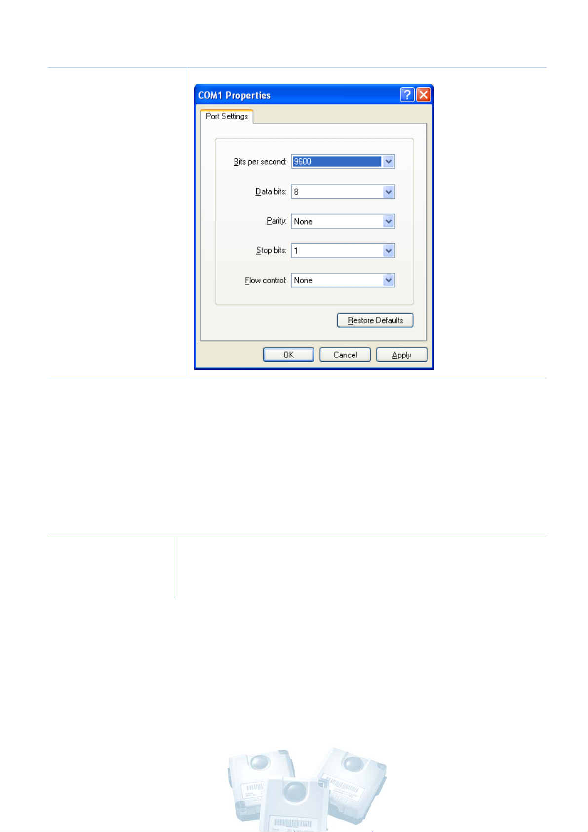
The correct COM
port settings. If
you cannot access
the CLI, try a
different COM port
number, such as
COM2 or COM3.
6. Switch on the tag by keeping the call / on-off button
down for 5 seconds
. Release when green status LED appears. It
pressed
may take up to 10 seconds until the tag displays its CLI prompt.
If the battery is too low or empty, you will get red status LED or
no light at all. Then plug the power cable in and try again.
NOTE
If the tag is already switched on, you may need to press the
Enter key once or twice to bring up the CLI prompt.
9
Page 9
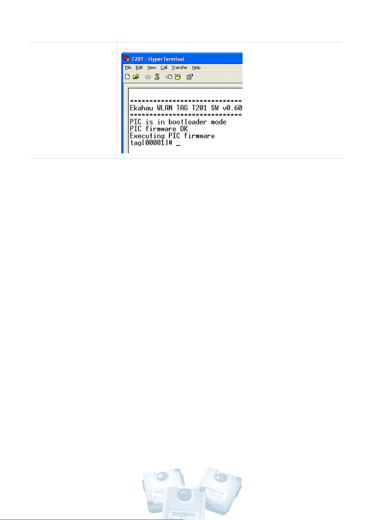
The CLI prompt
displays the
Ekahau tag
software version
and serial number
(or friendly name).
Using the Configuration Interface
Execute CLI commands with the
When you execute CLI commands, they are
immediately
without asking for confirmation.
List all configuration parameters by typing
Save the configuration changes to permanent memory by
typing
save
<Enter>. Any unsaved changes will be lost during
Enter
key.
activated
config<Enter>.
the next tag sleep or power-off period.
The command line is editable. You can move the cursor freely
left and right and delete single characters from the line.
The command history is 10 previous input lines. You can scroll
through the command history with
You can complete commands with the
Type
help
<Enter> to display the list of available commands.
up and down arrow keys
Tab
key.
Successfully executed commands will not generate any output.
Invalid commands will display an error message.
The command prompt format is
10
tag[serial number OR name]#
Page 10

Setting Parameter Value
Parameter values are set by typing the full parameter string and its
value to the command line. E.g. setting the associated network’s
name (SSID) to “test-wlan” and saving it to tag’s permanent memory:
tag[00001]#
tag[00001](unsaved)# save<Enter>
Any unsaved changes will be lost during the next tag sleep or power-
off period. Successful execution gives no feedback to the user.
Most text parameters such as
without double quotes (“ “) if the text does not contain empty spaces.
WEP
key however always requires the double quotes, when typed in
as plain text. The text itself cannot contain double quotes (“).
wlan ssid ”test-wlan”<Enter>
SSID and Engine password can be set
Displaying Parameter Value
Parameter values are displayed by typing the full parameter name
string to the command line. E.g. displaying the motion scan rate:
tag[00001]#
motion scan rate<Enter>
tag[00001]#
motion scan rate = 2 seconds
Error Messages
If the user enters an invalid command, one of the two error messages
may appear:
Parameter name not valid
Invalid parameter value
E.g. setting an invalid parameter value
tag[00001]#
Error: Invalid parameter value
periodic scan interval -1
<Enter>
11
Page 11

Minimum Configuration
To allow T201 associate with your Wi-Fi network and communicate
with the Positioning Engine, you must configure at least:
SSID (network name is always required)
Positioning Engine IP address (always required)
WEP key as a string or hex bytes (if WEP is enabled)
T201 IP address or method (if DHCP service is not available))
T201 friendly name (optional but recommended)
It is recommended to name each T201. The name will be displayed in
Ekahau Manager instead of IP address, and developers can read the
names via Ekahau SDK and YAX device property
GENERAL.NAME.
Minimum configuration with example values:
tag[00001]#
tag[00001]#
tag[00001]#
tag[00001]#
tag[00001]#
tag[00001]#
wlan ssid 1 MyNetworkName<Enter>
wlan wep 1 “HaRdeR2HackeR”
engine ip 192.168.1.1<Enter>
ip method static<Enter> (if DHCP is not available)
ip address 192.168.1.2
name Robert<Enter> (optional but recommended)
<Enter> (if DHCP is not available)
<Enter> (if WEP enabled)
tag[00001]#
The simplest
configuration with
SSID and Engine IP
address if DHCP is
available and there
is no WEP.
save<Enter>
12
Page 12

Configuring Multiple Tags
To configure tags faster, it is helpful to create a text file that contains
the preferred configuration settings, and send the file to the CLI with
any terminal program.
1. Open Windows Notepad or similar plain text tool, and write a
configuration parameter on each row. For example:
wlan ssid test-net<Enter>
engine ip 192.168.1.1
wlan wep 1 26:4d:29:42:34:28:4d:69:44:30:24:4d:29<Enter>
save
<Enter>
2. Save the file for example as T201_settings.txt.
3. Connect a T201 tag to your computer and open a terminal
program, such as HyperTerminal (see the previous chapters).
4. Select
supports several file transfer protocols, select ASCII.
5. Browse for the T201_settings.txt and click
Type
config<Enter> to verify the new configuration.
Transfer > Send Text File… If your terminal program
<Enter>
Changes from T101 Tags
Send
.
If you have used the Ekahau T101 tags, please note the following
changes and modify your configuration scripts accordingly:
•
T201 supports up to 4 different wep keys. The index of
the wep key has been added to the parameter ‘wlan wep
key’.
•
T201 supports up to 4 different SSIDs. The index of the
SSID has been added to the parameter ‘wlan ssid’.
•
The T201 does not support passive scanning. Scan mode
passive parameter is not available.
13
Page 13

Communication Parameters
These parameters are required to let the tag associate with the Wi-Fi
network and communicate with the Positioning Engine. You must
configure at least the
manual configuration), and Positioning Engine’s
SSID, the tag’s IP address (automatic DHCP or
IP address.
WLAN
Parameter Syntax Factory Min Max Type
WLAN SSID
index
wlan ssid 1 “SSID” OR
off
Configures up to 4
SSIDs
Tag attempts to use
SSIDs from index 1
to 4.
Attempts to use
different SSIDs, if
roaming has been
activated.
Ekahau 1 4 R/W
WLAN SSID
Roaming
WLAN WEP
index
wlan ssid roaming 0 OR
1
Activates WLAN
roaming using
different SSIDs
“1” = roaming
active
wlan wep 1 “key” OR
xx:xx:xx:xx OR off
configure up to 4
wep keys
tag attempts to use
keys from index 1
to 4
apply strings (“)
around plain text
apply colons (:)
0 0 1 R/W
Wep 1 off
wep 2 off
wep 3 off
wep 4 off
1 4 R/W
14
Page 14

between hex bytes
use exactly 5 or 13
characters (or hex
bytes) for 40/104
bit encryption
Note! The tag does
not give any
notification, if a wep
key is not valid.
IP method ip method dhcp OR
dhcp - - R/W
static
IP address ip address 10.10.10.10 10.10.10.10 - - R/W
IP netmask ip netmask
255.255.255.0 - - R/W
255.255.255.0
IP gateway ip gateway off off - - R/W
Engine
protocol
Positioning
engine protocol udp OR
udp - - R/W
tcp
engine ip 192.168.0.2 192.168.0.2 - - R/W
engine IP
Positioning
engine tcp port 8548 8548 - - R/W
engine tcp
port
Positioning
engine udp port 8549 8549 - - R/W
engine udp
port
Password engine password Llama Llama - - R/W
Engine
Retries
engine retries 1
number of retries
1 1 10 R/W
(if WLAN or EPE
connection drops)
before giving up
Scanned scan channels 1-14 1-14 - - R/W
15
Page 15

channels
Scan send
limit
scan send limit 1
how many Wi-Fi
scans are sent to
EPE per message
1 1 50 R/W
Limiting the Scanned Channels
Make sure that the scan channels setting complies with your national
802.11b channel restrictions:
Channels 1-11 are allowed in the US
Channels 1-13 are allowed in Europe, Middle-East, and Africa
Channels 1-14 are allowed in Japan
You can also limit the channels if certain channels are not used at all
in your network.
Set the allowed channels for example as:
scan channels 1-3, 6-11.
Periodic Parameters
These parameters allow the tag to ‘wake up’ periodically, for example
every 2 minutes, perform a network scan, communicate the results to
the Positioning Engine, and go back to ‘sleep’ to save battery.
Parameter Syntax Factory Min Max Type
Periodic
Active
periodic active 1 OR 0
“0” = no periodic
wakeups
1 0 1 R/W
16
Page 16

Periodic
Wakeup
Periodic Scan
Count (after
waking up)
Periodic Scan
Interval (after
waking up)
periodic wakeup
interval 120
time between the
periodic wakeups
periodic scan count 3
number of scans per
periodic wakeup
periodic scan interval 2
time between
the scan(s) during a
wakeup
Motion Parameters
120 (s) 0 86400 R/W
3 0 50 R/W
2 (s) 1 10 R/W
These parameters allow the tag to react to movement. Using these
settings wisely can significantly extend the tag’s battery life. It also
removes the need to query the tag location, as the tag will
automatically report its location whenever it is moved.
Special parameters are included for scanning after the tag has
detected that motion has ended. This is especially useful for asset
tracking applications.
Parameter Syntax Factory Min Max Type
Motion Active motion active 1 OR 0
“0” = no motion detection
Motion
Sensitivity
motion sensitivity 10
1 = most sensitive
100 = least sensitive
1 0 1 R/W
3 1 100 R/W
Motion Poll
Interval
motion poll interval 100
time between polls
0.2 (s) 0 100 R/W
17
Page 17

Motion
Threshold
Motion Dead
Time
Motion Scan
Count
motion threshold 1
how many sequential
positive accelerometer
polls are determined
as a motion event
motion dead time 5
after a motion event
accelerometer is not
polled until dead time
has elapsed. Used to
reduce too frequent
motion events
motion scan count 3
number of scans
triggered by a single
motion event
5 1 10 R/W
5.0 (s) 0 3600 R/W
3 0 50 R/W
Motion Scan
Interval
Aftermotion
active
Aftermotion
scan count
Aftermotion
scan interval
motion scan interval 1.5
scan interval for the
motion-triggered
scans (if more than 1)
aftermotion active 1 OR 0
enables scanning after
motion has ended
“0” = no after motion
scanning
motion scan count 3
number of scans
triggered after end of
motion was detected
motion scan interval 1.5
scan interval after end
of motion was
detected
1.0 (s) 1 10 R/W
0 0 1 R/W
3 0 50 R/W
1.5 (s) 1 10 R/W
18
Page 18

Call / On-Off Button Parameters
These parameters allow the tag to react to call button press. The
button can be used for example as a call or alarm feature.
button down for 5 seconds
to switch the tag on/off.
Press the
Parameter Syntax Factory Min Max Type
Button active button active yes OR no
yes - - R/W
no = no call button
feature, on/off still
2 (s) 1 10 R/W
3 0 50 R/W
Button scan
Interval
Button scan
works
button scan interval 2
Time between scans
based on buttonactivation
button scan count 3
Count
Button call
period
Number of buttonactivated scans
button call period 100
The time period the
tag sends the ‘call
button active’
information to the
server
Buzzer operation
The buzzer parameters control the operation of the internal audio
buzzer. The buzzer can be used for helping in finding the tag. The tag
audio signal and duration can be controlled using configuration
parameters from the command line interface. For activating the
60 (s) 0 3600 R/W
19
Page 19

buzzer remotely see Ekahau Device Manager documentation for
instructions.
Parameter Syntax Factory Min Max Type
Buzzer
pattern
buzzer pattern 01234567
OR
buzzer pattern
0CDEFGAB
Each number
represent different
buzzer frequency
0 = not active,
1 = note C = 2093 Hz,
2 = D = 2349 Hz,
3 = E = 2637 Hz,
4 = F = 2794 Hz,
5 = G = 3136 Hz,
6 = A = 3520 Hz,
7 = B/H = 3951 Hz
Sequence may include
any number of tones
- - 32
digits
R/W
The length of a
sequence is 96ms
Buzzer
duration
buzzer duration 1
Number of repetitions
of buzzer sequence
LED operation
The buzzer parameters control the operation of the internal audio
buzzer. The buzzer can be used for helping in finding the tag. The tag
audio signal and duration can be controlled using configuration
parameters from the command line interface. For activating the
1 - - R/W
20
Page 20

buzzer remotely see Ekahau Device Manager documentation for
instructions.
Parameter Syntax Factory Min Max Type
Led pattern led pattern GG-R
Each character
represent different
color or blank
R = red, G = green,
- = not active
Sequence may
include any number
of tones
Led duration led duration 1
Number of
repetitions of led
sequence
Maintenance operation
-GGRRGG- - 32
digits
1 - - R/W
R/W
Maintenance parameters control the setting of tag parameters
remotely from the Ekahau Device Manager (EDM) server. The
parameters define the server address and interval in seconds that the
tag requests new parameters from the EDM server. See more
information in the EDM documentation.
Command Syntax Factory Min Max Type
Maintenance
active
Maintenance
period
maintenance active 0
Maintenance
active/inactive
maintenance interval
100
Time interval
0 0 1 R/W
- 0 86400 R/W
21
Page 21

between
maintenance
requests
Maintenance
ip
Maintenance
port
maintenance ip
10.10.10.11
Ekahau Device
manager server ip
address
maintenance port 8000
Ekahau Device
manager server
port number
Other Parameters
These optional configuration parameters allow for example adding
user-defined value-key pairs that are available from the Positioning
10.10.10.11 - - R/W
8000 - - R/W
Engine’s application interface.
Parameter Syntax Factory Min Max Type
name name mytagname
This is the device
name displayed in
Ekahau Manager
Name can be read
via Ekahau SDK and
YAX protocol from
device property
GENERAL.NAME
Low Battery
Limit
WLAN
alarm battery low 3.4 3.4 (volts) 3.2 4.0 R/W
wlan powersave on OR
None - - R/W
off R/W
Powersave
off
NOTE: Enabling this
option may improve
22
Page 22

battery life up to
50%
Sleep WLAN sleep wlan 1 OR off
After this period of
time has elapsed
without event, the
WLAN module may
be put to sleep
WLAN module will
not sleep in case of
upcoming periodic,
motion, or button
event
off = never sleep
Sleep CPU sleep cpu 20
after this period of
time has elapsed
without event, the
CPU may be put to
sleep
off off 10 R/W
20 (s) off 3600 R/W
User defined
keys
However, CPU will
not sleep in case of
upcoming periodic,
motion, or button
event
off = never sleep
user key=va l ue OR
user clear <key>
These device
properties are
displayed in Ekahau
Manager and can be
read via Ekahau
Java SDK and YAX
(empty) - - R/W
23
Page 23

Commands
The tag commands are used for saving settings, displaying status,
calibrating, viewing statistics, help screen and upgrading the
embedded software.
Command Syntax Description
Configuration config Shows all configuration parameters
Calibrate calibrate Starts quick network scanning and
sending for calibration purposes
Select the corresponding T201
tag as the calibration client from
Ekahau Manager’s File >
Preferences dialog
Exit the calibration mode by
pressing ESC in the terminal
Debug level debug level <n>
n = 0 OR 1, 2, 3
Info info Displays static information
Help help Displays CLI-help
Debug display level for error
messages. Please note that the
setting canno t be saved.
MAC-address
Serial number
Ping ping <IP-address> PING-utility
Reset reset Resets the factory default settings
Save
configuration
Status status Displays TAG-status information
save Saves unsaved configuration to
permanent memory
IP-address
24
Page 24

battery charge
Software update swupdate
https://user:pass@10.10
.10.15/t201_070.zip
OR
swupdate
http://10.10.10.15/t201_
070.zip
OR
swupdate
ftp://10.10.10.15/t201_0
70.zip
Configuration Tips
Fetches and upgrades tag’s
embedded software from a server in
the network.
Supports http, https and ftp
protocols
When upgrading the tag software
plug the tag to the charger to
avoid accidental loss of power in
middle of upgrade.
Username and password are
optional.
Use software packages provided
by Ekahau only.
This section provides tips that guide you in selecting the optimal
configuration for your tags.
For best performance in accuracy it is recommended let T201 to
scan two times before sending both results to engine. This improves
Engines throughput and accuracy.
Ekahau recommends to use UDP protocol instead of TCP with larger
amount of T201’s that frequently send data to the Engine. This is
because of smaller overhead of the UDP protocol. Note that UPD
protocol transmission is not guaranteed.
To save battery power it is recommended to always use "Sleep
WLAN" option.
Ekahau recommends to use UDP protocol instead of TCP with larger
amount of T201’s that frequently send data to the Engine. This is
because of smaller overhead of the UDP protocol. Note that UPD
protocol transmission is not guaranteed.
TCP protocol is recommended for applications were it is essential for
the engine to receive all packets from the T201’s. TCP protocol
transmission is always guaranteed.
25
Page 25

T201 gives mistaken status "Associated" even if the WEP key is not
correct. This is because WLAN driver gives correct response that it
has "associated" to access point, but it does not inform if
"Authentication" was successful. To avoid problems with the
authentication make sure that the WEP key(s) are set correctly.
T201 supports roaming between different SSIDs. This is
implemented by scanning all audible networks and selecting the
SSID in index 1. If that is not audible then index 2 and so on. How
ever, if the signal of SSID index 1 is low enough, lower than -
80dBm, the index 2 is tried to use and so on. This way T201
ensures that it establishes good connection to network even when
the prior (index 1) network is audible with too low signal strength.
Following settings have proven to work well with the motion sensor:
motion sensitivity = 3
motion poll interval = 0.200 seconds
motion threshold = 5
motion dead time = 5.000 seconds
CHAPTER 3: Technical Specifications
Enclosure
Outside Dimensions (mm): 49 x 56 x 23
Weight (g): 85
Power switch with configurable Call button function
Tag and battery status indication with two 2-color LED
Buzzer for voice signals
Wi-Fi
Operating Temperature: 0 to 50 ºC [32…140ºF]
Storage Temperature: -10 to 70 ºC[-4…158ºF]
Humidity: From 20% to 90 % non-condensing, relative humidity
Environmental Protection: IP53/NEMA12, protected against dust
and spraying water
Supported Wi-Fi Specification: v1.1
Supported IEEE Standards: 802.11b/g/d
26
Page 26

Modulation Scheme: Direct Sequence Spread Spectrum (DSSS)
Media Access: CSMA/CA
Receiver Sensitivity: -82dBm@11Mbps
Output power: 14 dBm +/- 1.0 dBm
Frequency Range: 2.412 - 2.484 GHz
Supported Networking Protocols: TCP/IP, UDP/IP, DHCP
Security: WEP Encryption 40/128 Bit
Antenna Type: Internal omni-directional ceramic multilayer
Average Antenna Gain: -3dBi
NOTE
The T201’s 802.11b chipset works with 802.11g access points,
but, as any standard 11b device, will decrease the associated
802.11g access point’s data rate to the maximum of 11 Mbps.
Operating Ranges from an Access Point
Open Space: 100m (330ft)
Typical Office: 30m (100ft)
Configuration
Command Line Interface (CLI)
Connectivity: Serial cable (included)
Terminal Emulation: VT100
Line Parameters: 9600 bps, 8 data bits, no parity bit, and 1 stop bit
Minimum Configuration: SSID, tag IP method, Engine IP address
Optional Configuration: WEP, motion/button/periodic scan on/off,
scan intervals, sensitivity to motion, etc.
Battery Life
Can be used with external power source (5V DC, 800mA)
Battery: Integrated 1800mAh Li-Ion rechargeable
The T201 has power for approximately 2500 wakeups, network
scans, and data deliveries, depending on network load, using the
WLAN powersave option
27
Page 27

Expected 3-5 day battery life with 5 min periodic wakeup
Expected 24 hour battery life with 10 sec periodic wakeup
Application Interface (EPE)
Ekahau Positioning Engine 3.1 (EPE) provides a flexible Java™ and
Ekahau YAX™ application interfaces for reading the location
information
Certifications
FCC Rules
This device complies with Part 15 of the FCC Rules. Operation is
subject to the following two conditions:
(1) this device may not cause harmful interference, and
(2) this device must accept any interference received, including
interference that may cause undesired operation.
FCC ID of this device is: TA7-T201-2.
Note: This equipment has been tested and found to comply with the
limits for a Class B digital device, pursuant to part 15 of the FCC
Rules. These limits are designed to provide reasonable protection
against harmful interference in a residential installation. This
equipment generates, uses and can radiate radio frequency energy and,
if not installed and used in accordance with the instructions, may
cause harmful interference to radio communications. However, there is
no guarantee that interference will not occur in a particular
installation. If this equipment does cause harmful interference to radio
or television reception, which can be determined by turning the
equipment off and on, the user is encouraged to try to correct the
interference by one or more of the following measures:
Reorient or relocate the receiving antenna.
Increase the separation between the equipment and receiver.
Connect the equipment into an outlet on a circuit different from
that to which the receiver is connected.
Consult the dealer or an experienced radio/TV technician for help.
28
Page 28

FCC RF Radiation Exposure Statement
This equipment complies with FCC Radio Frequency Electromagnetic
Signal (RF) exposure limits set forth for an uncontrolled environment
of portable transmission. This product has been evaluated for RF
exposure at a distance of 0,5 cm (0,2 inches). Operation at a separation
distance less than 0,5 cm (0,2 inches) from the radiating element to
nearby persons will expose nearby persons to RF levels that exceed
the FCC rules for RF exposure.
CE Marking
This device has been tested and meets the Electromagnetic
Compatibility (EMC) requirements of EN50082-1 and EN50022 for the
CE Declaration of Conformity (DoC).
CHAPTER 4: Care and Limited Warranty
Care and Maintenance
The tag is a product of superior design and craftsmanship and should
be treated with care. The suggestions below will help you to fulfill any
warranty obligations and to use this product for many years.
Keep the tag dry. Precipitation, humidity and all types of liquids or
moisture can contain minerals that will corrode electronic circuits.
Do not use or store the tag in dusty, dirty areas. Its moving parts
can be damaged.
Do not store the tag in hot areas. High temperatures can shorten
the life of electronic devices, damage batteries, and warp or melt
certain plastics.
Do not store the tag in cold areas. When it warms up (to its normal
temperature), moisture can form inside, which may damage
electronic circuit boards.
The operating temperature of the tag is 0 to 50 °C. Do not operate
the tag outside this temperature range.
Do not attempt to open the tag. Non-expert handling may damage
it.
Do not drop, knock or shake the tag. Rough handling can break
internal circuit boards.
29
Page 29

Do not use harsh chemicals, cleaning solvents, or strong detergents
to clean the tag.
Do not paint the tag. Paint can clog the moving parts and prevent
proper operation.
Use a soft, clean and dry cloth to clean the tag.
Use only the supplied antenna. Unauthorized antennas,
modifications or attachments could damage the tag and may violate
regulations governing radio devices.
All of the above suggestions apply equally to your tag, battery,
charger or any accessory.
Limited Warranty
Ekahau warrants that the Tags will operate in accordance with and
substantially conform to their published specifications when shipped
or otherwise delivered to the end user and for a period of 180 days
thereafter, provided, however, that Ekahau does not warrant any
claim or damage under this Warranty if such claim or damage results
from:
1. Misuse, neglect, accident or improper installation or maintenance
of the Tags,
2.
Tags that have been altered, modified, repaired, opened or
tampered with by anyone other than Ekahau,
3. Use of the Tags not in compliance with their respective
documentation, user manuals, instructions, and any usage
restrictions contained therein, including, but not limited to, the
provisions relating to the environment and ranges where the tags
must be used, or
4. Accident, fire, power failure, power surge, or other hazard.
Otherwise, the Tags are sold AS IS. In no event does Ekahau warrant
that the Tags are error free or that end user will be able to operate the
Tags without problems or interruptions.
End User is responsible for using the Tags within their specifications
as contained in the Documentation.
30
Page 30

Notice of Warranty Claims
The End User must contact Ekahau promptly if he/she has a valid
warranty claim with respect to the Tags. To be valid, the claim must
be made within two hundred (200) days of shipment or other delivery
to the End User. The contact must be made to Ekahau customer
support and must contain a detailed written description of the
suspected claim/malfunction, the date of purchase, and the serial
numbers of the Tags. Ekahau customer support email address is
support@ekahau.com
.
The End User shall cooperate with Ekahau in providing such
additional information as may be required for Ekahau to investigate
whether the user has a valid warranty claim, including shipping the
Tags back to Ekahau, if so requested.
The End User agrees that he/she shall return, or contact Ekahau
regarding, warranty claims for a minimum of 10 Tags at one time.
Ekahau shall not have any obligation to handle warranty claims for a
shipment or a call relating to less than 10 Tags at one time.
31
 Loading...