

Airgo Networks AGN1202AP0000 User Manual

7 Managing Security
encryption provides no protection, and is only recommended when security is not of concern.
WPA-AES is recommended for all installations, if possible.
Table 12: Encryption Options
Type Description
AES Highest level of protection
TKIP WEP with additional protection
WEP 128 First generation encryption using 128-bit keys, does not provide adequate
WEP 64 First generation encryption using 64-bit keys, does not provide adequate
Open No protection
Configure and view the following aspects of network and user security from the web interface:
• Wireless Security—Select protocols for data encryption and user authentication.
• Authentication Zones—Group resources for user authentication.
• Administrator Security—Set the administrator login and password to access the AP.
• RADIUS Servers—Identify authorized RADIUS servers and zones.
• Security Statistics—View security-related statistics, including authentication, 802.1x
• Advanced—Configured advanced RADIUS properties.
protection
protection
supplicant, and authentication diagnostic statistics.
Configuring Wireless Security
Choose Wireless Security from the Security Services menu to configure the protocols for data
encryption and user authentication. The Wireless Security panel contains two tabs:
• Security Mode—Configure WPA, WEP, or open encryption and authentication.
• SSID Auth—Identify the authentication server for the SSID.
Security Mode
Use the Security Mode tab (Figure 102) to assign the encryption and authentication methods,
including WPA, WEP, or Open. Allowing multiple encryption modes can be useful to support
installations with a mixture of client wireless adapters. There are some limitations to the allowed
combinations; it is not possible to enable both WEP and Open simultaneously. Also, Open and
WPA encryption modes require each mode to be mapped to a separate VLAN (see “Configuring
VLANs” on page 105).
138 Installation and Configuration Guide: Airgo Access Point
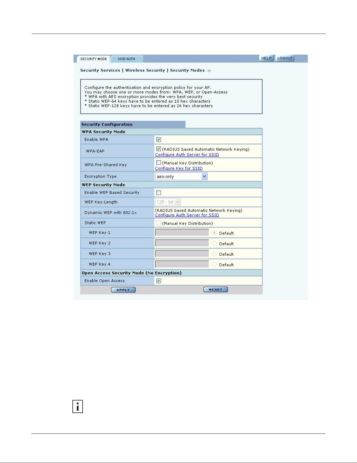
Figure 102: Security Services - Security Mode
Configuring Wireless Security
WPA Security
Select Enable WPA to activate the WPA authentication and encryption fields. The following
options are available:
Field Description
WPA Security Mode WPA-EAP—For RADIUS-based networking keying
WPA-PSK—For pre-shared keys
Encryption Type AES, TKIP, AES and TKIP
Click Apply to save the configuration, or Reset to return to the previously saved values.
WPA provides strong encryption support with the AES and TKIP algorithms.
NOTE: Some early versions of WPA-capable client software may not permit a client to
associate to the AP when multiple modes off encryption and authentication are chosen.
Installation and Configuration Guide: Airgo Access Point 139

7 Managing Security
WEP Security
If it is necessary to configure WEP security, select Enable WEP to activate the WEP fields.
Configure the following values in the WEP security area:
Field Description
Enable WEP Activate the WEP settings. The Airgo AP supports WEP with dynamic and
Key-Length Select 64-bit or 128-bit
Key 1 - Key 4 For manual keys, enter up to four WEP key values. Each WEP key is 26 hex-
Click Apply to save the settings or Reset to clear the fields on the panel.
Open Access
Select Enable Open Access to omit data encryption. A pop-up message warns of the potential
security risk in using open access. Click OK to continue.
NOTE: Selecting WPA-EAP or WPA-PSK displays a link that leads to the SSID
Authentication tab. Refer to “SSID Authentication” on page 140 for instructions on
using this tab.
manually entered keys. To use dynamic keys, select WEP, but do not enter
values in the Key fields.
ASCII characters. (required if security mode is WEP)
SSID Authentication
Use the SSID Authentication tab (Figure 103) to assign RADIUS Authentication servers or a WP A
pre-shared key. RADIUS based authentication uses lists of servers, called authentication zones,
which are provided by the Airgo AP security portal or an external RADIUS server. Each SSID can
be configured with the RADIUS servers used for EAP authentication and the WPA pre-shared key
(if applicable).
MAC-ACL lookups can be enabled for clients that associate with WPA-PSK, manual WEP-keys,
or with no security. MAC-ACL is not applicable if per user authentication is done where user name
is available.
140 Installation and Configuration Guide: Airgo Access Point
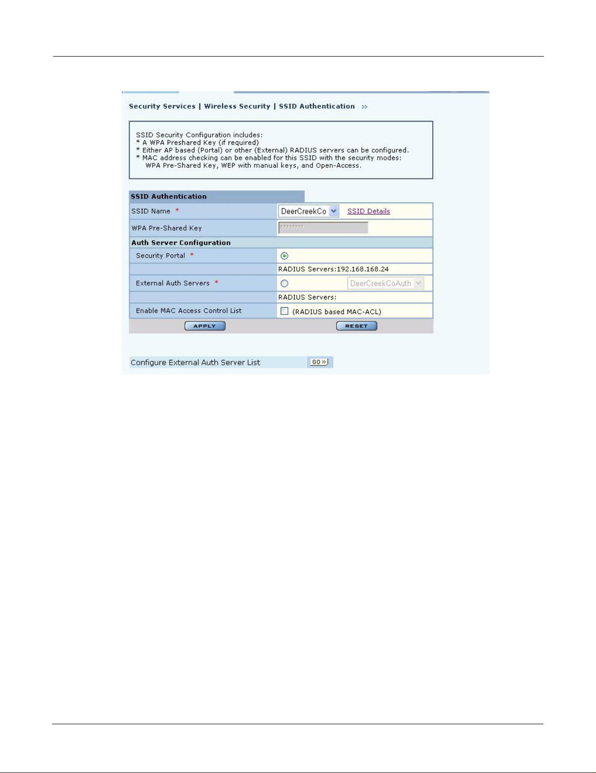
Figure 103: Security Services - SSID Auth
Configuring Wireless Security
Assign the following values to configure SSID authentication:
Feature Description
SSID Name Select from the SSID pull-down list. Click SSID Details to view more SSID-
related information, enable multiple SSIDs, or change other SSID attributes.
WPA Pre-Shared Key Enter the pre-shared key for WPA, if appropriate. This field is grayed out if
WPA-PSK is not the selected authentication type.
Authentication Server
Configuration
Enable MAC Access
Control List
Select the Security Portal or External Authentication Server radio button. For
Security Portal, the IP addresses of all security portals are displayed below the
radio button. For External security, select from the list of RADIUS servers or
click Go at the bottom of the tab to configure the authentication server list
(see “Authentication Zones” on page 143). (required)
Select to enable authentication using MAC addresses that are centrally
managed in a RADIUS server. For MAC-ACL authentication, it is necessary
to use a security portal or external RADIUS server.
Click Apply to save changes or Reset to return to previously saved values. It may be necessary to
click Back on your browser to return to the Security Configuration panel. Make sure to also click
Apply on the Security Configuration panel.
An external RADIUS server can also be added from this tab. Click Go at the bottom of the tab to
open the Authentication Zone tab of the Authentication Zones panel. For instructions on adding a
server, refer to “Configuring Authentication Zones” on page 143.
Installation and Configuration Guide: Airgo Access Point 141

7 Managing Security
If an external RADIUS server is to be used for MAC address based ACL lookups, the following
apply:
1 The RADIUS server must have PAP authentication enabled for these MAC ACL users
2 The RADIUS server can expect the AP to send the following standard RADIUS attributes in
Attribute Description
User-Name MAC address
User-Password MAC address
Message-Authenticator RADIUS extension providing enhanced authentication of message contents.
NAS-IP-Address Management IP address of the AP
NAS-Port Radio interface number for the associating station
NAS-Port-Type Standard value Wireless - IEEE 802.11. Indicates that the user has requested
3 The RADIUS server should enforce a policy such that MAC ACL users are only allowed to use
the authentication request for purposes of policy configuration and interoperability. (MAC
addresses must be in sent with no colon or hyphen separators):
(This is the same as the signature attribute in some RADIUS servers).
access via an 802.11 port on the AP.
PAP authentication for Wireless. This is important because the username and password are not
secret.
4 The RADIUS server may optionally send back the Session-Timeout attribute to override the
AP default session-timeout.
5 The RADIUS server may optionally send back an attribute encoded with the user group.
If an external RADIUS server is used for EAP based authentication (with WPA or with legacy
802.1x), the following information should be used when configuring the server:
1 The RADIUS server can expect the AP to send the following standard RADIUS attributes in
the authentication request for purposes of policy configuration and interoperability:
Attribute Description
User-Name Contains the MAC address in the format specified above.
EAP-Message Contains the EAP messages received from the station.
Framed-MTU Contains a hint to help the RADIUS server for EAP fragmentation
Message-Authenticator The RADIUS extension that provides enhanced authentication of the message
contents. (Also referred to as signature attribute in some RADIUS servers).
NAS-IP-Address Contains the management IP address of the AP.
NAS-Port Contains the radio interface number on which the station is associating.
NAS-Port-Type Contains the standard value “Wireless - IEEE 802.11” to indicate that the
user to be authenticated has requested access via an 802.11 port on the AP.
2 The RADIUS server can use these attributes to enforce policies such that EAP based
authentication is mandatory for Wireless.
3 The RADIUS server may optionally send back the “Session-Timeout” attribute to override the
AP default session-timeout.
142 Installation and Configuration Guide: Airgo Access Point
4 The RADIUS server may optionally send back an attribute encoded with the user group.
Configuring Authentication Zones
RADIUS servers may be used to authenticate wireless users and administrative users, and to check
MAC Access Control Lists for the SSID.
Select Authentication Zones from the Security Services menu to define zones for RADIUS
authentication and to add external RADIUS servers to the list of available authentication servers.
Configure the servers first, and then include them in zones.
The Authentication Zone panel contains two tabs:
• Auth Zones—Define zones for RADIUS authentication.
• Auth Servers—Add RADIUS servers.
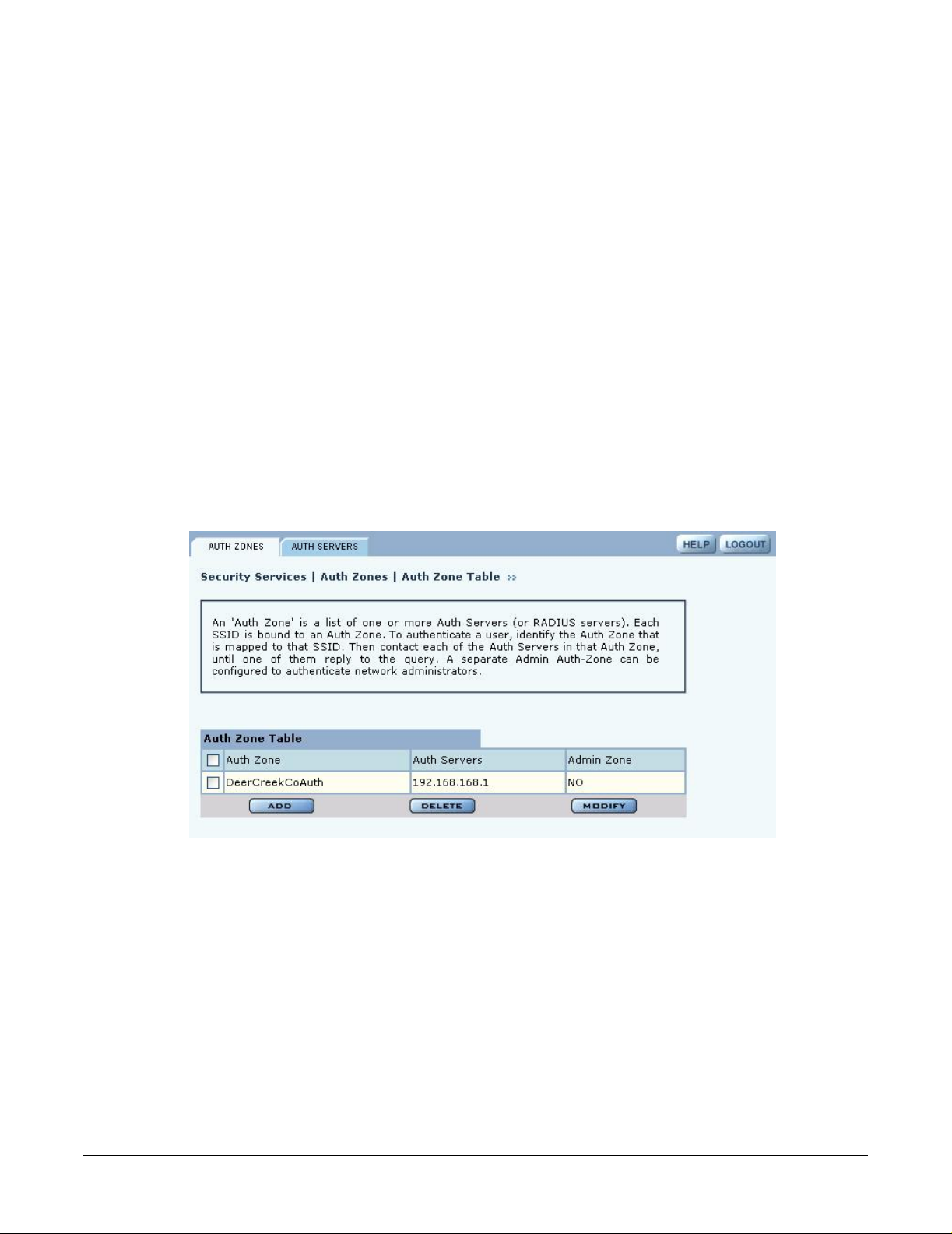
Authentication Zones
On the Authentication Zones tab (Figure 104), you can create new authentication zones or modify
existing ones. Select check boxes for authentication zones you want to modify or delete, or click
Add to add a new zone.
Figure 104: Authentication Zones - Auth Zones
Configuring Authentication Zones
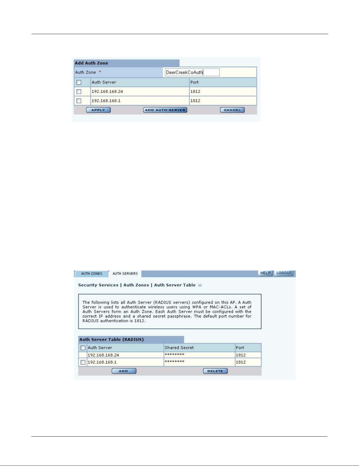
Set the following values on the Add Auth Zone entry panel (Figure 105):
Field Description
Auth Zone Name of the authentication zone.
Auth Server list List of possible servers to add to the zone. Select desired servers.
Click Add after making selections.
Installation and Configuration Guide: Airgo Access Point 143
7 Managing Security
Figure 105: Authentication Zones - Add Auth Zone s
To add a new authentication server, click Add Auth-Server, and enter the following values for
each new RADIUS server:
Field Description
Auth Server IP address of the RADIUS authentication server.
Shared Secret Enter and confirm the secret key.
Port Number Port number for the server (default is 1812).
Click Add to save the values, or click Reset to clear the fields on the panel.
Click Back on your browser to return to the Auth Zone panel. Set an authentication zone for
administrative users by selecting from the pull-down list.
Authentication Servers
Open the Authentication Servers tab (Figure 106) to view the current authentication servers and
add or delete servers.This table shows the list of both internal (security portals) and external auth
servers. The servers that do not have a check box against them are security portals.
Figure 106: Authentication Zones - Auth Servers
Configuring Administrator Security
Choose Administrator Security from the Security Services menu to open the Administrator
Security panel (Figure 107).
144 Installation and Configuration Guide: Airgo Access Point

Figure 107: Administrator Security - Admin Password
Configuring Administrator Security
Set the following values on this panel:
Field Description
Change Local Admin
Password
RADIUS Authentication
for Network
Administrator Login
Enter the old password and the new password, and confirm the new password.
This password is used for the local administrative login and the SNMPv3
administrative login. (required)
Select whether to use the Portal AP security feature for network administrator
authentication or use an external RADIUS server. With the external RADIUS
server option, links are available to add, delete, or edit the list of servers.
(required)
Click Apply to save the settings or Reset to clear the fields on the panel.
External RADIUS Server Settings
The following rules apply for an external RADIUS server:
• The external RADIUS server must have Password Authentication Procedure (PAP)
authentication enabled for administrative users.
• The Airgo AP sends a standard RADIUS attribute called “Service-Type” in the authentication
request. The value of this attribute is set to “Administrative” to indicate that the user to be
authenticated has requested access to an administrative interface on the AP
• If the user authentication is successful, the RADIUS server must send back an Airgo vendor-
specific attribute defined as follows:
vendor-id=13586, vendor sub-type=3, integer value = 1.
Installation and Configuration Guide: Airgo Access Point 145
7 Managing Security
This attribute informs the AP that the user is not normal user, but rather an administrator who
may be granted access to the privileged administrative interface.
Viewing Security Statistics
Choose Security Statistics item from the menu tree to open the Security Statistics panels. This
panel contains the following tabs:
• Auth Stats—View authentication statistics for each selected AP radio.
• Suppl Stats (Supplicant Statistics)—View statistics on 802.1x requests, for each selected BP
radio.
• Auth Diag—View authentication diagnostics statistics, including back-end data.
Each of the tabs includes a Reset button to return the statistics to zero and begin collecting them
again.
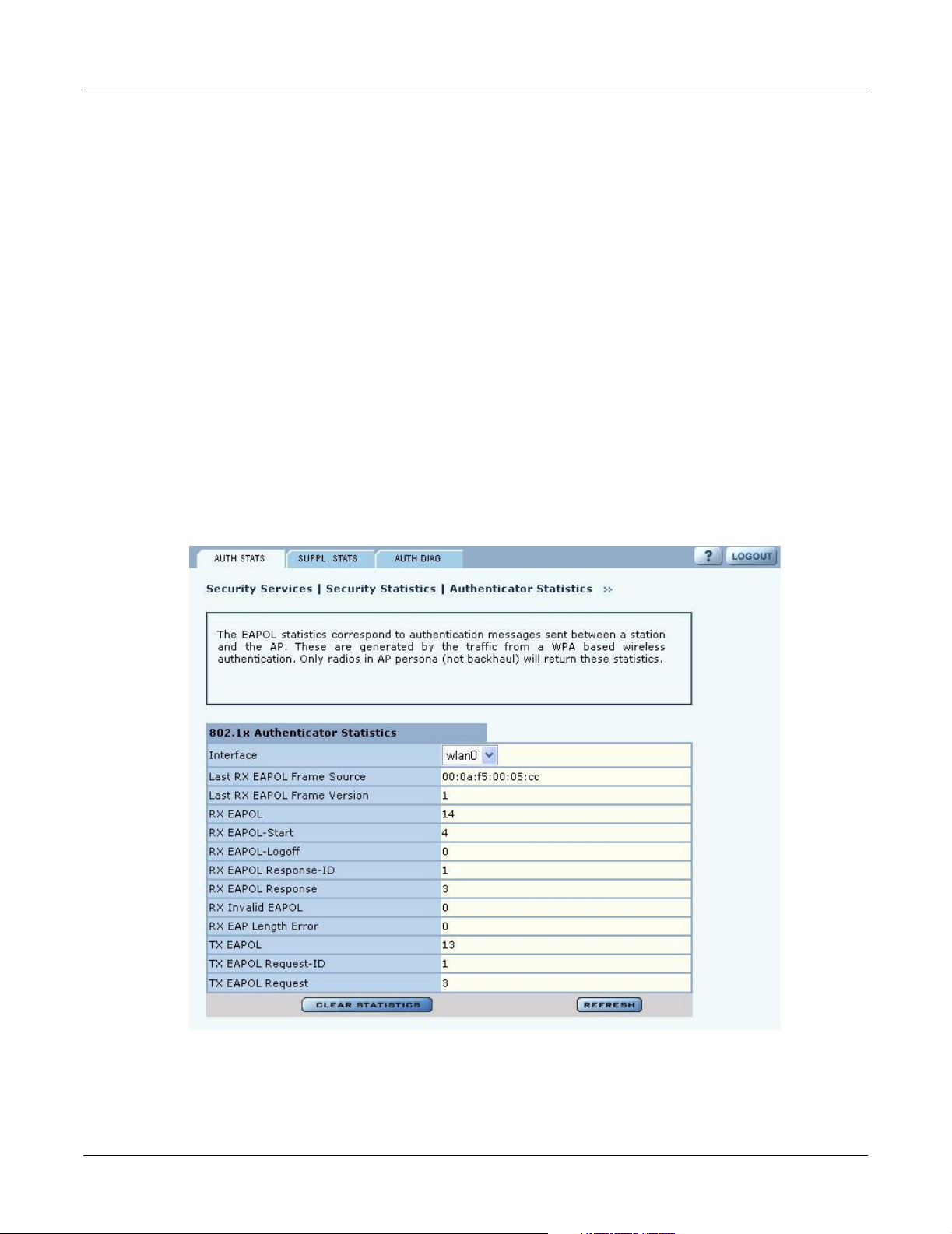
Authentication Statistics
The Authentication Statistics tab (Figure 108) contains EAPOL statistics, which correspond to
authentication messages sent between a station and an AP. These are generated by the traffic from
WPA or 8021.x based wireless authentication. Only radios in AP mode produce this data.
Figure 108: Security Statistics - Authentication Stats
146 Installation and Configuration Guide: Airgo Access Point

Viewing Security Statistics
The tab contains the following information:
Field Description
Interface Select the radio interface of interest for viewing statistics.
Last RX EAPOL Frame
Source
Last RX EAPOL Frame
Version
RX EAPOL The total number of EAPOL frames received by the AP.
RX EAPOL-Start The total number of EAPOL-Start frames received by the AP. This count
RX EAPOL-Logoff The total number of EAPOL-Logoff frames received by the AP. This count
RX EAPOL Response-IDThe total number of EAPOL based EAP Response-ID frames received by the
RX EAPOL Response The total number of EAPOL based EAP Response frames received by the AP
RX Invalid EAPOL The total number of EAPOL frames received by the AP that have invalid
RX EAP Length Error The total number of EAPOL frames received by the AP that have invalid
The source MAC address from the last EAPOL frame received by the AP.
This identifies a station or BP that is currently authenticating or re-
authenticating with the AP.
The EAPOL version from the last EAPOL frame received by the AP.
increments as stations or BPs request the AP to start their authentication
sequence.
may not increment as most 802.1x peers do not send this frame for security
reasons.
AP. This count increments as stations or BPs present their user-id or device-id
information to the AP at the start of the authentication sequence.
that do not contain an EAP Response-ID. This count increments as the AP
receives authentication credentials derived from passwords or certificates
from stations or BPs that are authenticating with it.
packet type fields. These frames are discarded by the AP.
packet body length fields. These frames are discarded by the AP.
TX EAPOL The total number of EAPOL frames transmitted by this AP.
TX EAPOL Request-ID The total number of EAPOL based EAP Request-ID frames transmitted by
this AP. This count increments as the AP sends authentication frames to
stations or BPs requesting them to return their user-id or device-id information
at the very start of the authentication sequence.
TX EAPOL Request The total number of EAPOL based EAP Request frames transmitted by the
AP that do not contain an EAP Request-ID. This count increments as the AP
transmits authentication credentials derived from passwords or certificates to
the stations or BPs that are authenticating with it.
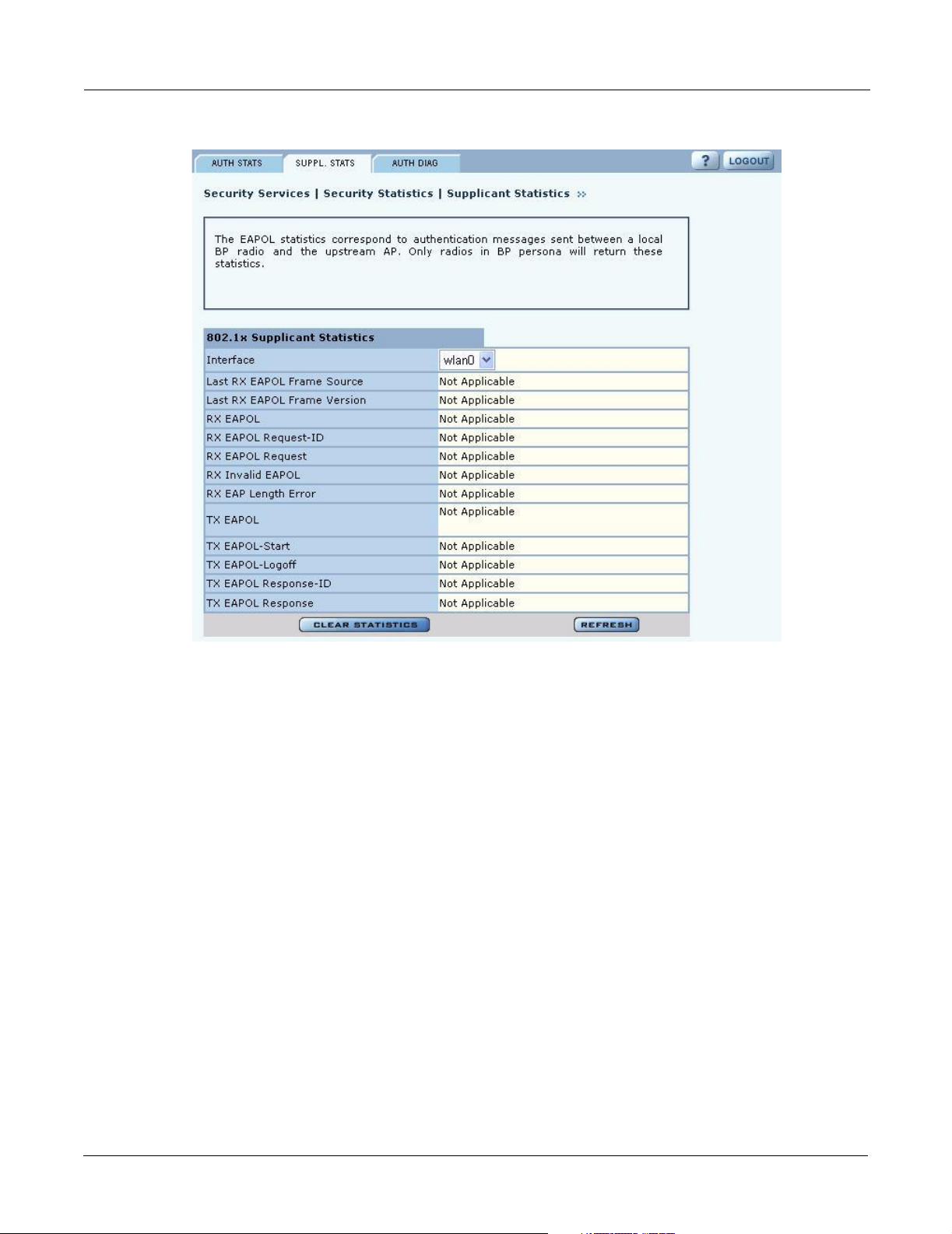
Supplicant Statistics
The Supplicant Stats tab(Figure 109) reports on authentication messages sent between a local BP
radio and the upstream AP. Only radios in BP mode return these statistics. The statistics are
generated from the EAPOL protocol, which is used for 802.1x authentication.
Installation and Configuration Guide: Airgo Access Point 147
7 Managing Security
Figure 109: Security Statistics - Supplicant Stats
The tab contains the following information:
Field Description
Interface Select the radio interface of interest for viewing statistics.
Last RX EAPOL Frame
Source
Last RX EAPOL Frame
Version
RX EAPOL The total number of EAPOL frames received by the BP.
RX EAPOL Request-ID The total number of EAPOL based EAP Request-ID frames received by this
RX EAPOL Request The total number of EAPOL based EAP Request frames received by the BP
RX Invalid EAPOL The total number of EAPOL frames received by the BP that have invalid
RX EAP Length Error The total number of EAPOL frames received by the BP that have invalid
The source MAC address from the last EAPOL frame received by the BP.
This identifies the upstream AP that is currently authenticating or re-
authenticating with the BP.
The EAPOL version from the last EAPOL frame received by the BP.
BP. This count increments as the AP sends authentication frames to the BP
requesting it to its device-id information at the very start of the authentication
sequence.
that do not contain an EAP Request-ID. This count increments as the AP
transmits authentication credentials derived from certificates to the BP.
packet type fields. These frames are discarded by the BP.
packet body length fields. These frames are discarded by the BP.
148 Installation and Configuration Guide: Airgo Access Point
Viewing Security Statistics
Field Description
TX EAPOL The total number of EAPOL frames transmitted by this BP.
TX EAPOL-Start T he total number of EAPOL-Start frames transmitted by the BP. This count
goes up as the BP requests the AP to start its authentication sequence.
TX EAPOL-Logoff The total number of EAPOL-Logoff frames transmitted by the BP. This count
will not increment as the BP does not send this 8021.x frame for security
reasons.
TX EAPOL Response-IDThe total number of EAPOL based EAP Response-ID frames transmitted by
this BP. This count increments as the BP sends authentication frames to the
AP with its device-id information at the very start of the authentication
sequence.
TX EAPOL Response The total number of EAPOL based EAP Response frames transmitted by the
BP that do not contain an EAP Response-ID. This count increments as the BP
transmits authentication credentials derived certificates to the AP that is
authenticating with it.
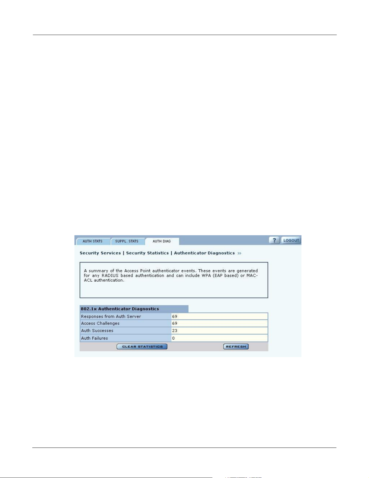
Authentication Diagnostics
The Authentication Diagnostics tab (Figure 110) contains a summary of the Access Point
authenticator events received from a backend authentication server. These events are generated for
any RADIUS based authentication and can include WPA (EAP based) or MAC-ACL
authentication.
Figure 110: Security Statistics - Authentication Diagnostics
The tab contains the following information:
Field Description
Responses from Auth
Server
Access Challenges The total number of RADIUS authentication packets that contained an
Installation and Configuration Guide: Airgo Access Point 149
The total number of RADIUS authentication related packets received from the
backend authentication server.
ACCESS-CHALLENGE. These are sent by the RADIUS server when it is
engaged in a multi-step authentication sequence.
7 Managing Security
Field Description
Auth Successes The total number of RADIUS authentication packets that contained an
ACCESS-ACCEPT. These are sent by the RADIUS server when the
authentication sequence succeeds.
Auth Failures The total number of RADIUS authentication packets that contained an
ACCESS-REJECT. These are sent by the RADIUS server when the
authentication sequence fails.
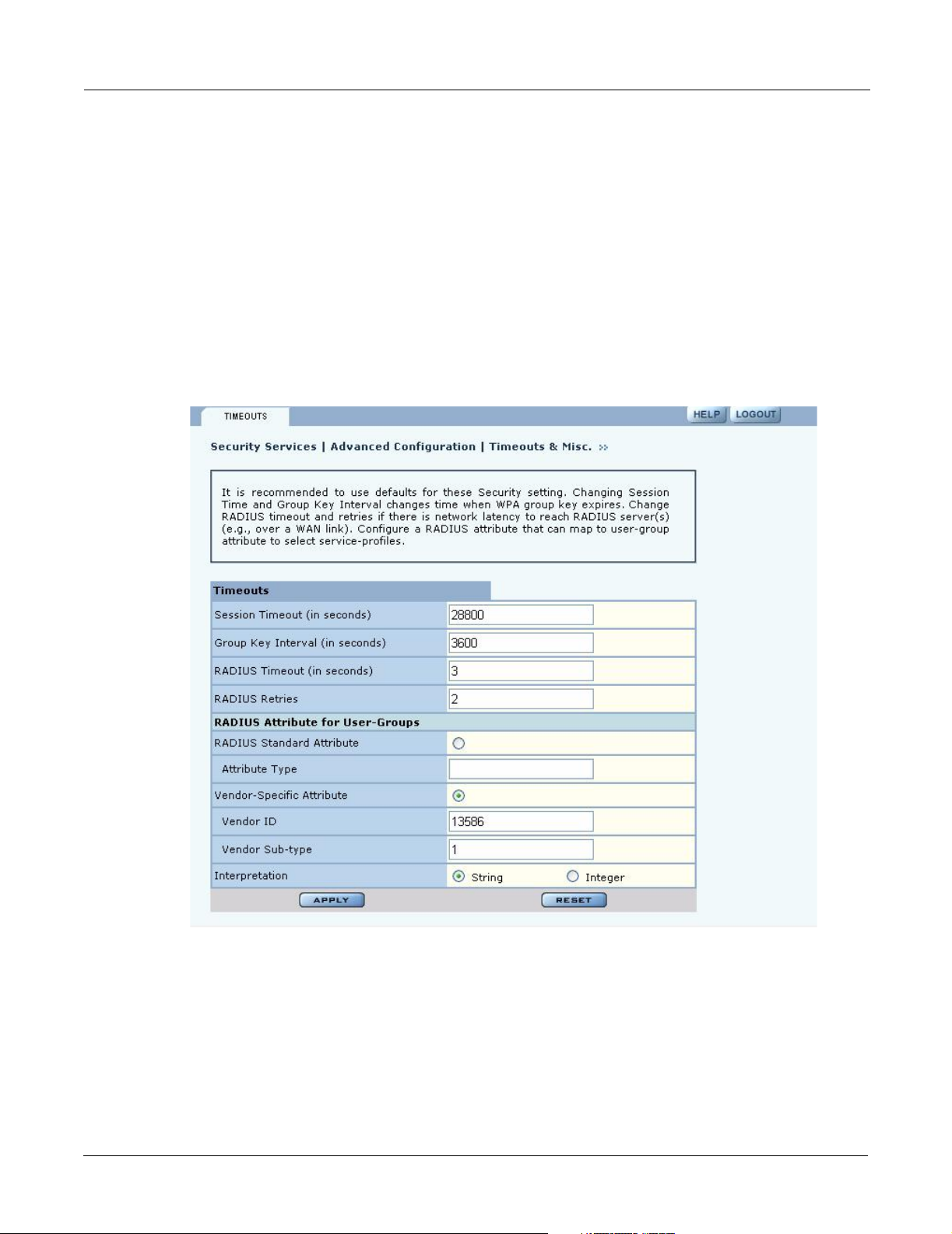
Configuring Advanced Parameters
Choose Advanced Configuration from the menu tree to open the Advanced RADIUS
configuration panel (Figure 111). It is not necessary to modify any of the settings on this panel.
Figure 111: Advanced Configuration - Timeou ts
The panel contains the following fields:
Field Description
Session Timeout Time in seconds, after which a station is re-authenticated
Group Key Interval Time in seconds, after which the group key is changed. This is not used if
static WEP keys are enforced
RADIUS Timeout Time in seconds, after which the request is retransmitted
150 Installation and Configuration Guide: Airgo Access Point

Configuring Advanced Parameters
Field Description
RADIUS Retries Number of retransmit attempts, after which the RADIUS request is marked a
failure.
External RADIUS
Group-Key Attribute
(for User Group ID)
RADIUS attribute used by the AP to determine the user group (see “SSID
Details” on page 82). When a wireless user is authenticated by a RADIUS
server, the server can optionally send the AP the ‘User Group’ for the
association. If a user group is not returned, then the user is not assigned a
group, and the user gets the default service profile for the SSID. By default, a
Vendor Specific Attribute is used (13586, 1, String).
Other standard or vendor specific attributes can be used to determine service policies. For example,
an enterprise having an existing RADIUS attribute for VLANs can reuse the attributes for AP
service profile assignments by configuring them as the RADIUS attributes for user groups.
Click Apply to implement the changes, or click Reset to return the entries on the panel to their
previous values.
Installation and Configuration Guide: Airgo Access Point 151

7 Managing Security
152 Installation and Configuration Guide: Airgo Access Point

8
Overview
Configuring Guest Access
This chapter describes how to enable guest user access to the wireless network while protecting the
network from unauthorized use. It contains the following sections:
• Overview
• Configuring Guest Access
• Guest Access Services Panel
Guest access can be used to allow visitors to a facility to access the Internet through the wireless
network without gaining access to the corporate network. Most current guest user solutions require
guests to access a separate access point that is not part of the corporate network. The Airgo solution
eliminates this requirement by restricting guest access through VLAN tags on the existing access
points. There is no need to set up special access points or to physically restrict the locations used for
guest access.
Unauthenticated users are permitted to associate to an AP, but any web communications are
captured and directed to a controlled landing page, the “captive portal.” The landing page allows
the guest user to login using a web-based password scheme. The page can inform unauthenticated
users of the network access policies and provide instructions on obtaining the guest password.
Following successful authentication, the guest user is released from the captive pages and allowed
to access any resource on the guest VLAN.
The VLAN configuration of the upstream network should make available only those network
resources set aside for guest use. This often means prohibiting guest stations from accessing
anything other than the corporate open subnet or the Internet.
For open guest access, the open access security option must be configured. This precludes the use
of WEP Security Mode on APs that provide guest access, but does permit use of WPA Security
Mode.
VLANs and security privileges are assigned to users by way of service profiles defined for user
groups and bound to the network SSID. It is required that the VLAN configuration include DHCP
and DNS services.
Guest user authentication can be implemented using an internal or external landing page.
Installation and Configuration Guide: Airgo Access Point 153
8 Configuring Guest Access
Internal Landing Page
The internal landing page is a configurable option within the Airgo AP. The guest password for the
AP can be set using the Guest Access panel, or an automatically generated password can be
configured through the User Management panel in NM Portal. If the automatically generated g uest
password is used, then the authentication process for the internal landing page also checks the
password entered by the guest user against the RADIUS authentication service provided in the
Airgo security portal. If either password is acceptable, the guest user is authenticated and receives
the privileges specified in the guest service profile.
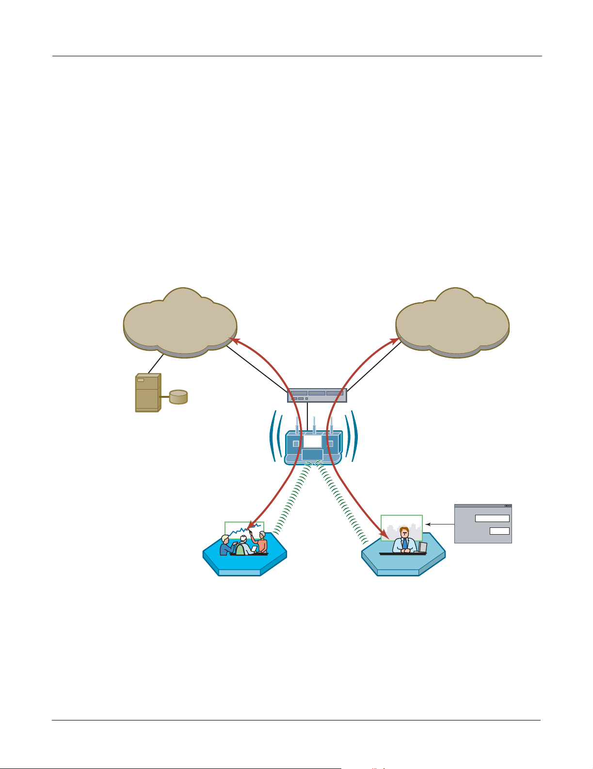
Figure 112 shows how Acme Works configured guest access with an internal guest landing page.
The company has two VLANs: Corporate and Guest. Corporate and guest users belong to the
Enterprise and Guest user groups, respectively, with appropriate service profiles assigned and
bound to the SSID. Corporate users are authenticated by way of the enterprise RADIUS server,
while guest users are authenticated by way of an internal landing page co nfig ured i n the Airgo AP.
After they are authenticated, guest users are place in the Guest VLAN.
Figure 112: Guest Access - Internal Landing Page
CorporateVLAN
RADIUS
Server
CorporateVLAN
Corporate
VLAN Switch
GuestVLAN
Guest
GuestVLAN
ID
Password
Guest Access
A0045B
154 Installation and Configuration Guide: Airgo Access Point
External Landing Page
An external landing web page can be set up through a corporate web server. The URL for the
landing page must use an IP address rather than a domain name. Regardless of the authentication
process selected for the external page, it is necessary to forward authentication results to the AP
upon completion of successful or unsuccessful guest authentication.
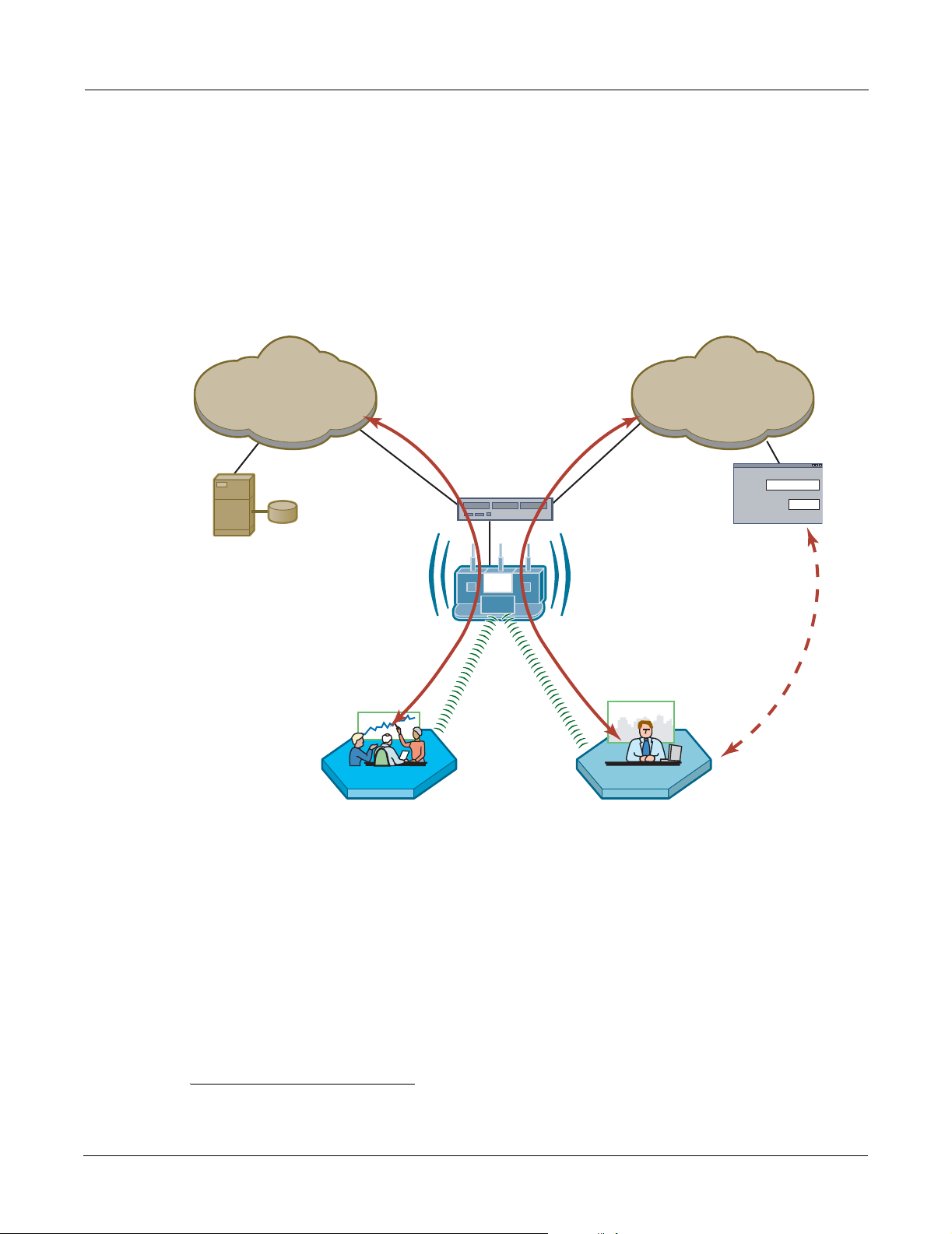
Figure 113 shows a network configuration with an external guest landing page. The external
landing page is made accessible over the Internet through an external web server. As in the previous
example, authenticated guest users are given access to the guest VLAN.
Figure 113: Guest Access - External Landing Page
External Landing Page
1
CorporateVLAN
RADIUS
Server
CorporateVLAN
Corporate
GuestVLAN
GuestVLAN
VLAN Switch
Password
Authentication
Results Passed
Back to AP
Web
Authentication
Guest
A0045B
1
An example external landing page is shipped with the Airgo AP.
Installation and Configuration Guide: Airgo Access Point 155

8 Configuring Guest Access
Open Subnet
In an optional open subnet arrangement, shown in Figure 114, unauthenticated guest users are
permitted limited access to an open enterprise subnet specified in the Airgo AP. The enterprise
open subnet must be part of the Guest VLAN. Extended access requires authentication through an
internal or external landing page.
Figure 114: Guest Access - Open Subnet
Open Access
Server
Open Subnet
Internet
Configuring Guest Access
This section describes the complete process of setting up guest access. A Guest Access wizard is
also available for easy configuration of the major guest access parameters. See “Guest Access
Wizard” on page 50 for instructions on using the Guest Access wizard.
VLAN Switch
No Direct Internet Access
Until Authenticated
GUEST-VLAN
Open Subnet
Address Range
User Group = "GUEST"
A0035B
Task Steps
Confirm that open access
is supported as a security
option.
1 Choose Wireless Security from the Security Services menu to open the
Security Mode tab (“Configuring Wireless Security” on page 138).
2 Enable WPA security, if mixed mode security (encrypted and open) is
desired. Only WPA can be enabled in conjunction with open. The WPA
Security mode is for non-guests only.
3 Enable Open Access.
4 Click Apply.
156 Installation and Configuration Guide: Airgo Access Point

Task (continued) Steps
Configuring Guest Access
Create or confirm
existence of a corporate
VLAN. This can be the
default untagged VLAN
or a specially created
VLAN.
1 Choose VLAN Configuration from the Networking Services menu to
open the VLAN table (“VLAN Table” on page 106).
2 Confirm that the corporate VLAN is listed in the table, or click Add to
create a new VLAN:
a Enter the corporate VLAN name and a numeric VLAN ID in the Add
VLAN entry panel.
b Enter the IP address and maskbits of the captive portal server, or select
the DHCP option. The guest portal must have a valid IP address for the
authentication process to work.
c Select the eth0 interface, and mark it as tagged. (Only eth0 should be
tagged.)
d Click Add.
Create the guest VLAN. 1 Choose VLAN Configuration from the Networking Services menu to
open the VLAN table (“VLAN Table” on page 106).
2 Click Add.
3 Enter the VLAN name (Guest VLAN) and a numeric VLAN ID in the Add
VLAN entry panel. It is not recommended to use the default VLAN.
4 Enter the IP address and maskbits of the captive portal server, or select the
DHCP option.
5 Select the eth0 interface, and mark it as tagged. (Only eth0 should be
tagged.)
6 Click Add. For additional information on configuring VLANS, see
“Configuring VLANs” on page 105.
Create or confirm
definition of a corporate
service profile.
Create a guest service
profile which specifies
the guest VLAN and
desired COS and security
options.
1 Choose SSID Configuration from the Wireless Services menu to open
the SSID table (“SSIDs and Service Profiles” on page 79).
2 Click Profile Table.
3 Add a corporate profile, or confirm that one exists with the desired WPA
security option and the corporate VLAN specified. Make sure that the
corporate profile is bound to the SSID.
1 Choose SSID Configuration from the Wireless Services menu to open
the SSID table.
2 Select SSID Details (“SSID Details” on page 82).
3 Confirm the SSID name, or enter a new SS ID name for the Guest Portal,
and then click Apply.
4 Click Profile Table to display the current list of service profiles.
5 Click Add to create the guest service profile. Select the VLAN ID for the
guest VLAN previously defined. Enter the COS value and make sure that
no-encryption is selected.
6 Click Apply.
Installation and Configuration Guide: Airgo Access Point 157

8 Configuring Guest Access
Task (continued) Steps
Add guest access to the
SSID and specify an
internal or external
landing page for guest
users who attempt to
access the network.
For the internal landing
page, set a guest
password; for an external
landing page use the
RADIUS shared secret
code.
Set up optional autogeneration of guest
passwords
1 Choose Guest Access Configuration from the Guest Access Services
menu to open the Guest table.
2 Click Add.
3 Confirm selection of the SSID and guest profile, as defined in the previous
task.
4 Select whether the landing page will be internal or external. If external,
enter a URL and an external web server secret code, which is the shared
secret code for communication between the AP and web server.
5 Click Apply.
1 If Internal is selected as the landing page type, click Security to enter the
guest password.
2 Enter and confirm the password, and then click Apply.
1 From NM Portal (Network Management Explorer) window, select User
Management from the Security Portal menu.
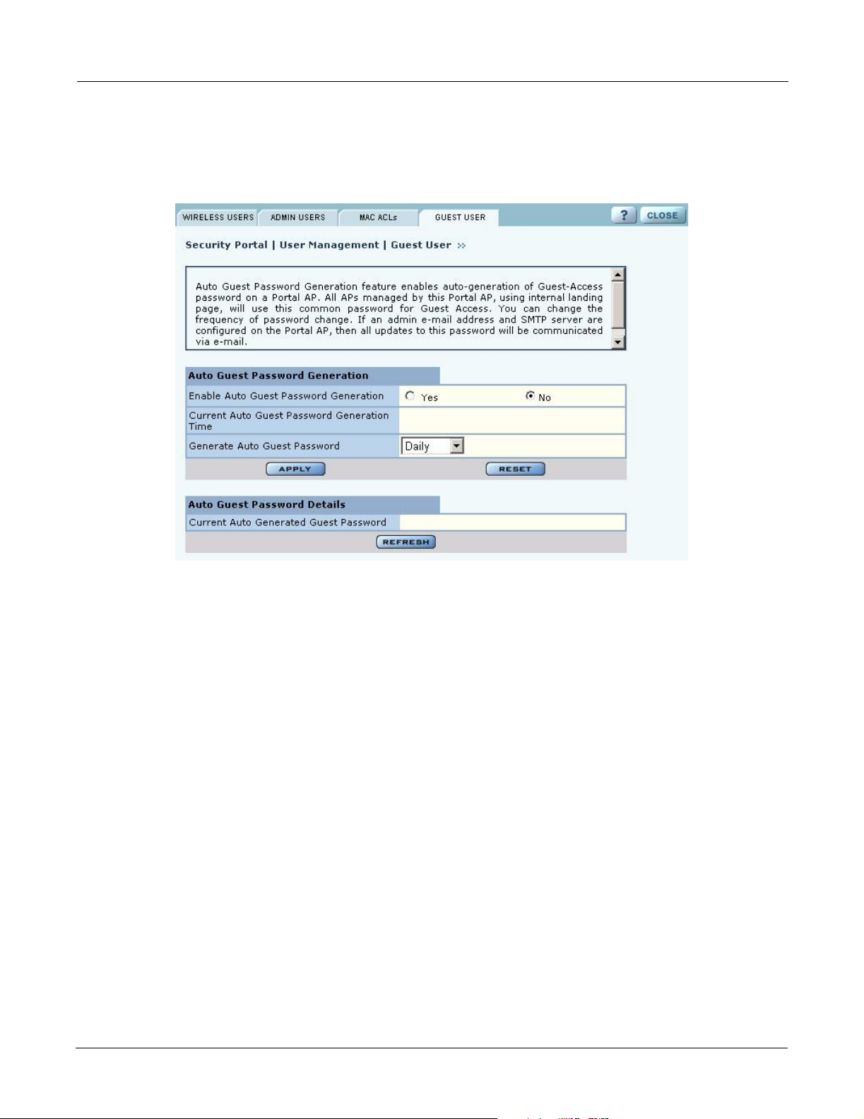
2 On the Guest User tab (Figure 117), select Yes to enable auto-password
generation.
3 Select an interval from the Generate Auto Guest Password pull-down list.
4 Click Apply.
NOTE: If static and auto-generated passwords are configured, then a guest
user can enter either password to be authenticated.
Guest access is now configured. When guests attempt to access the network, they are directed to an
external landing page or to a standard user login screen. Upon entering the correct guest password
or server secret code, they are granted access to the guest VLAN. They are also given the COS and
encryption characteristics specified in the guest service profile.
Guest Access Services Panel
For summary information about guest access, use the Guest Access Configuration panel. The panel
opens to the Guest table
presents the following information:
Field Description
SSID The network to which the guest profile belongs. There can be at most one
Service-Profile The name of the guest service profile bound to the SSID
Landing Page Internal or external page automatically displayed when guest users attempt to
Allowed Guest Subnet The subnet optionally reserved for unauthenticated guest access. Configuring
(Figure 115), which lists currently defined guest service profiles. The table
guest profile per SSID.
access the network
an allowed guest subnet can give unauthenticated users access to a limited set
of free services.
158 Installation and Configuration Guide: Airgo Access Point
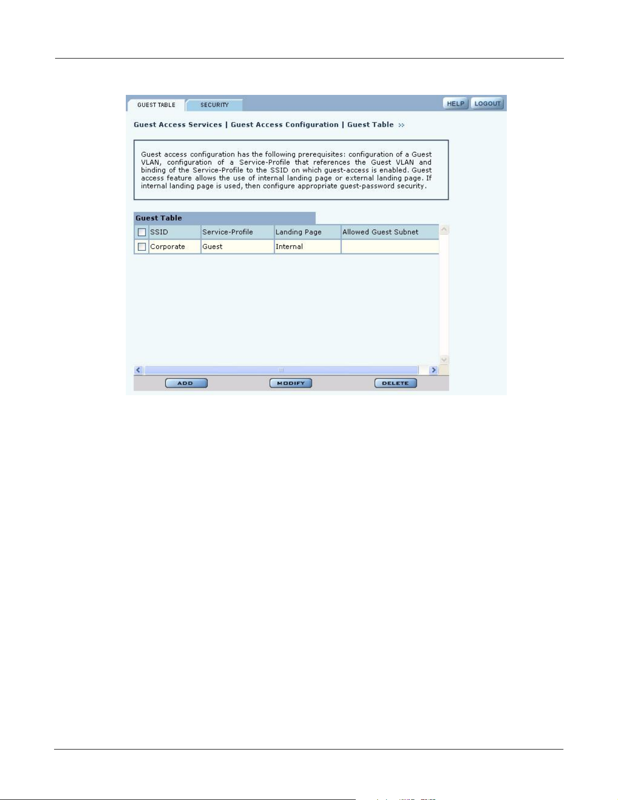
Figure 115: Guest Access Configuration - Guest Table
Guest Access Services Panel
Perform the following functions from the Guest Table:
Function Description
Add an entry to the
Guest Table
Modify an entry 1 Select the entry you wish to modify, and click Modify.
One guest profile can be added for each SSID. If a profile is already assigned
to an SSID and you add a new one, it replaces the previously defined profile.
1 Click Add.
2 Select the SSID.
3 Select the service profile from the Profile pull-down list.
4 If desired, enter the address and maskbits for a subnet optionall y reserved
for unauthenticated guest access.
5 Select an internal or external landing page. If the external page is selected,
enter the full URL and the shared secret code used for communicating with
the RADIUS server.
6 Click Apply.
2 Confirm the SSID.
3 Select the service profile from the Profile pull-down list.
4 If desired, enter the address and maskbits for a subnet optionall y reserved
for unauthenticated guest access.
5 Select an internal or external landing page. If the external page is selected,
enter the full URL and shared secret code for access.
Click Apply.
Installation and Configuration Guide: Airgo Access Point 159
8 Configuring Guest Access
Function Description
Delete an entry 6 Select the entry and click Delete.
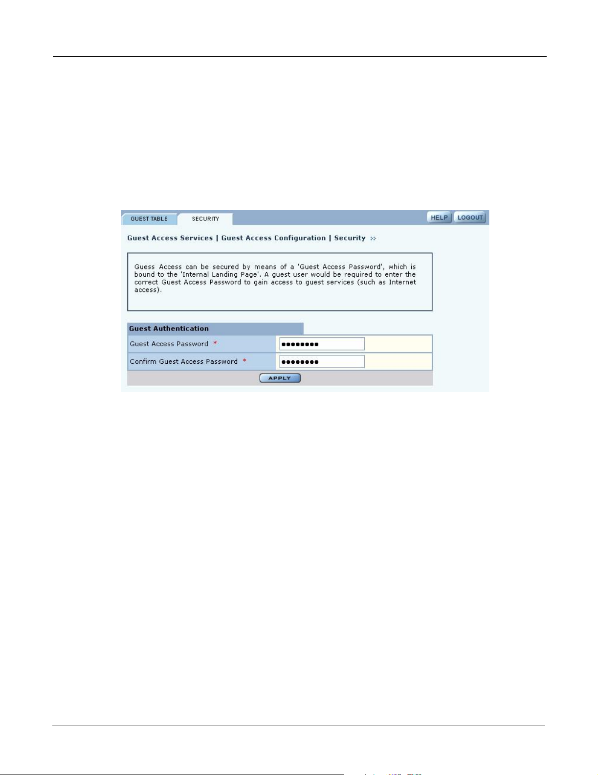
Guest Access Security
The Security tab of the Guest Access Configuration panel (Figure 116) provides an interface to set
the guest password for an internal landing page.
Figure 116: Guest Access Configuration - Security
7 Click OK to confirm.
160 Installation and Configuration Guide: Airgo Access Point
Guest Access Services Panel
Auto-Generating Guest Passwords
For optional generation of guest passwords automatically at set intervals, use the Guest User tab
within the security area of NM Portal
Figure 117: Security Portal - Guest User
(Figure 117).
Installation and Configuration Guide: Airgo Access Point 161

8 Configuring Guest Access
162 Installation and Configuration Guide: Airgo Access Point

Managing the Network
9
This chapter explains how to use the NM Portal features of the Airgo Access Point to manage
multiple APs across the network. It includes the following topics:
Introduction
Network management refers to the coordinated control and supervision of multiple access points
across a network. Network management functions include single-point configuration of multiple
access points, user access control, performance monitoring, and fault management.
• Introduction
• Using NM Portal
• Using the Network Topology Menu
• Managing Rogue Access Points
• Using the NM Services Menu
• Managing Network Faults
• Managing Users
Airgo offers the unique advantage of a network management capability built into the Airgo Access
Point. When configured as an NM Portal, the Airgo AP can provide network management services
for up to five subnetworks. For small to mid-size networks, this eliminates the need for an external
network management application. For mid to large size enterprise networks, NM Portal can be used
to manage all the APs at a specific location or branch, while NMS Pro, offered as a separate
product, can supply enterprise-level network management.
NM Portal supports the following functions:
• Single view to manage the entire network
• AP discovery
• AP enrollment
• Centralized software distribution and policy management
• Integrated security management for users
• Rogue AP control
• Email alerts
• Fault management
• Syslog
• Guest access control
Installation and Configuration Guide: Airgo Access Point 163
9 Managing the Network
Using NM Portal
To use the Airgo AP for NM Portal services, it is necessary to initialize (bootstrap) the unit in NM
Portal mode. Do so when initially configuring the AP, or by resetting the AP to factory defaults
prior to booting. Chapter 3, “Installing the Access Point,” explains how to initialize an NM Portal
and how to reset to factory defaults.
NOTE: Before resetting the AP to factory defaults, make sure to have the original
password shipped with the unit available.
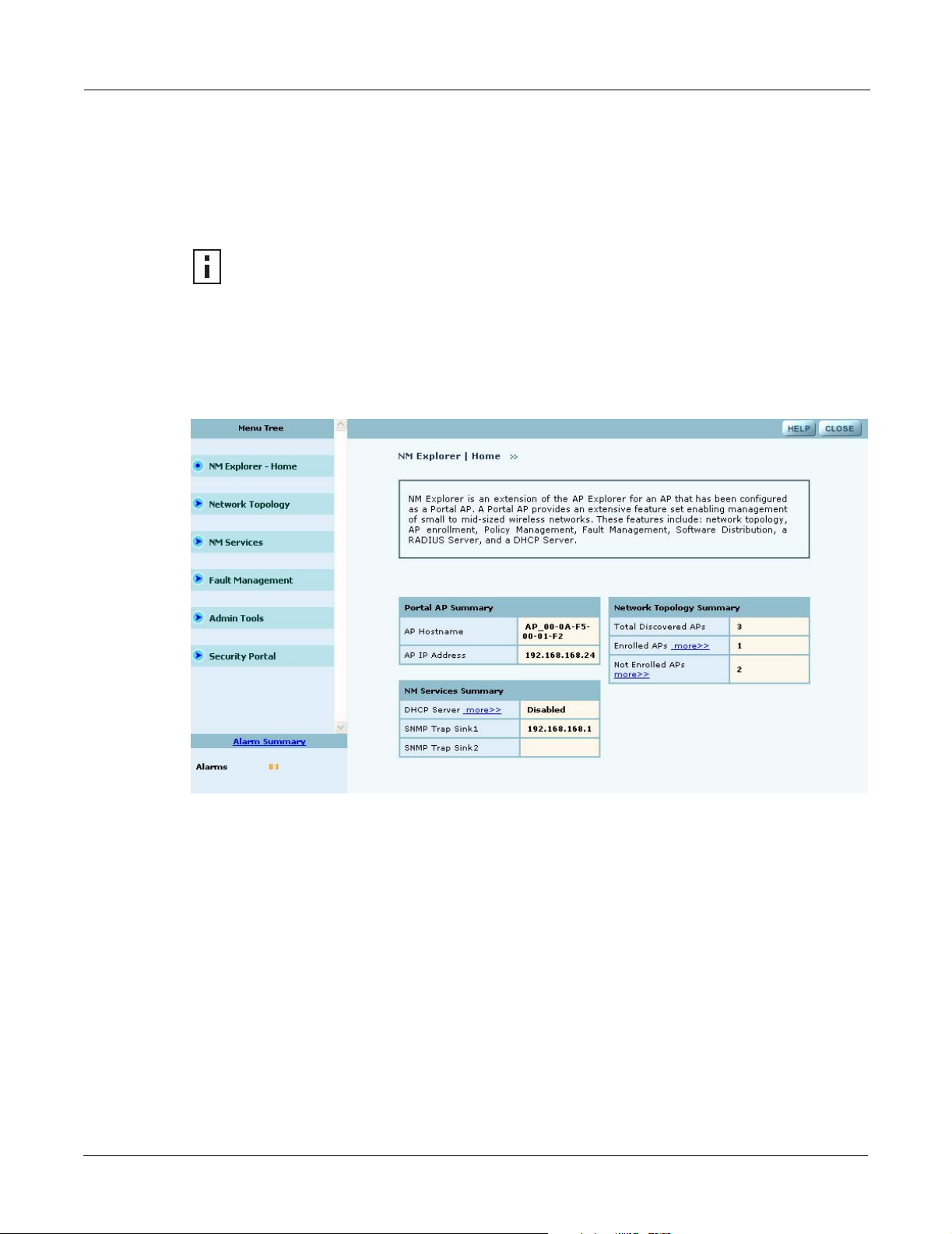
After the AP is initialized as a portal, access NM Portal services from the web interface at any time
by clicking Manage Wireless Network on the menu tree or on the Home panel (“The Home
Panel” on page 37). The NM Portal Network Management Explorer opens in a new browser
window (Figure 118).
Figure 118: NM Portal Web Interface
This interface is similar to that of the standard Airgo AP web interface. The menu tree on the left
contains a set of menus to access application features. Use the detail panels on the right to set the
configuration and monitor the state of the network. The alarm panel in the lower left portion of the
window shows the number of outstanding critical alarms collected across the NM Portal managed
network.
Home Panel
The Home panel (Figure 118) contains summary information about the network configuration
together with links to some of the Detail panels. Open the Home panel at any time by selecting
Home from the menu tree.
Menu Tree
The menu tree contains the following menus:
• Home—Open the Home panel.
164 Installation and Configuration Guide: Airgo Access Point
• Network Topology—Manage AP enrollment, wireless backhaul, IP address status, and radio
neighbors.
• NM Services—Set up network discovery, DHCP settings, and portal settings.
• Fault Management—View alarm logs and syslog events.
• Admin Tools—Upgrade AP software (see “Upgrading Software” on page 219).
• Security Portal—Add network, administrative, and legacy users.
Each of these topics is described in this chapter, except Software Upgrade, which is described in
Chapter 10, “Maintaining the Access Point.”
Click the arrow to the left of a menu item to expand the menu.
Using the Network Topology Menu
Use the Network Topology menu items to manage the identification, network status, and
relationship of APs in the network.
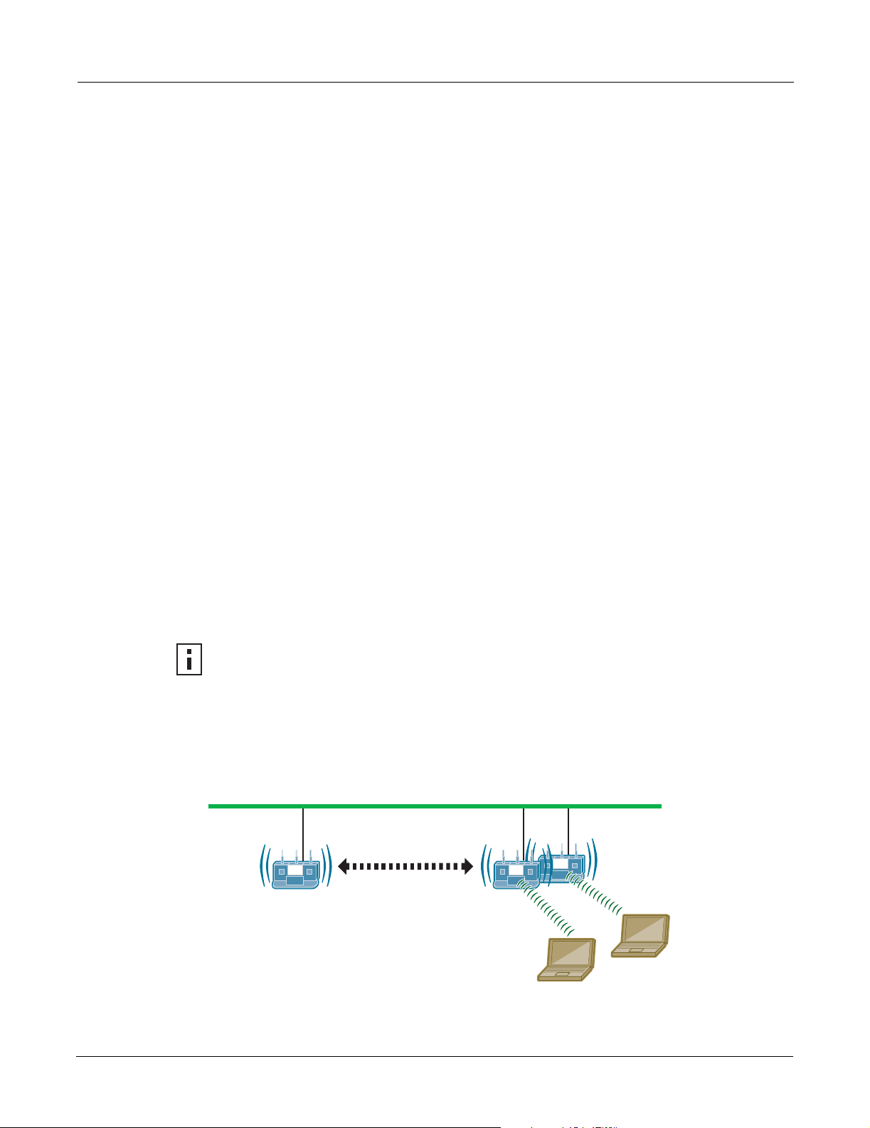
Enrolling APs
Network security depends upon mutual trust between the NM Portal and the other managed Airgo
APs. Each access point must trust the identity of the NM Portal AP, and the NM Portal must trust
that each access point is fully authenticated (Figure 119). Enrollment is the process used to
establish this mutual trust. The process consists of several steps:
Using the Network Topology Menu
• NM Portal automatically discovers all the Airgo Access Points and presents those that are not
already enrolled in a list of unenrolled APs.
• You select a candidate AP to enroll and verify its identity.
• NM Portal and the AP perform a mutual authentication process.
• Once the authentication is complete, the AP is enrolled. It is not necessary to enroll the AP
again, even if power is lost to the unit.
NOTE: In order to enroll an AP, it must be in the factory default state. This assures that
enrollment will be based on a known configuration.
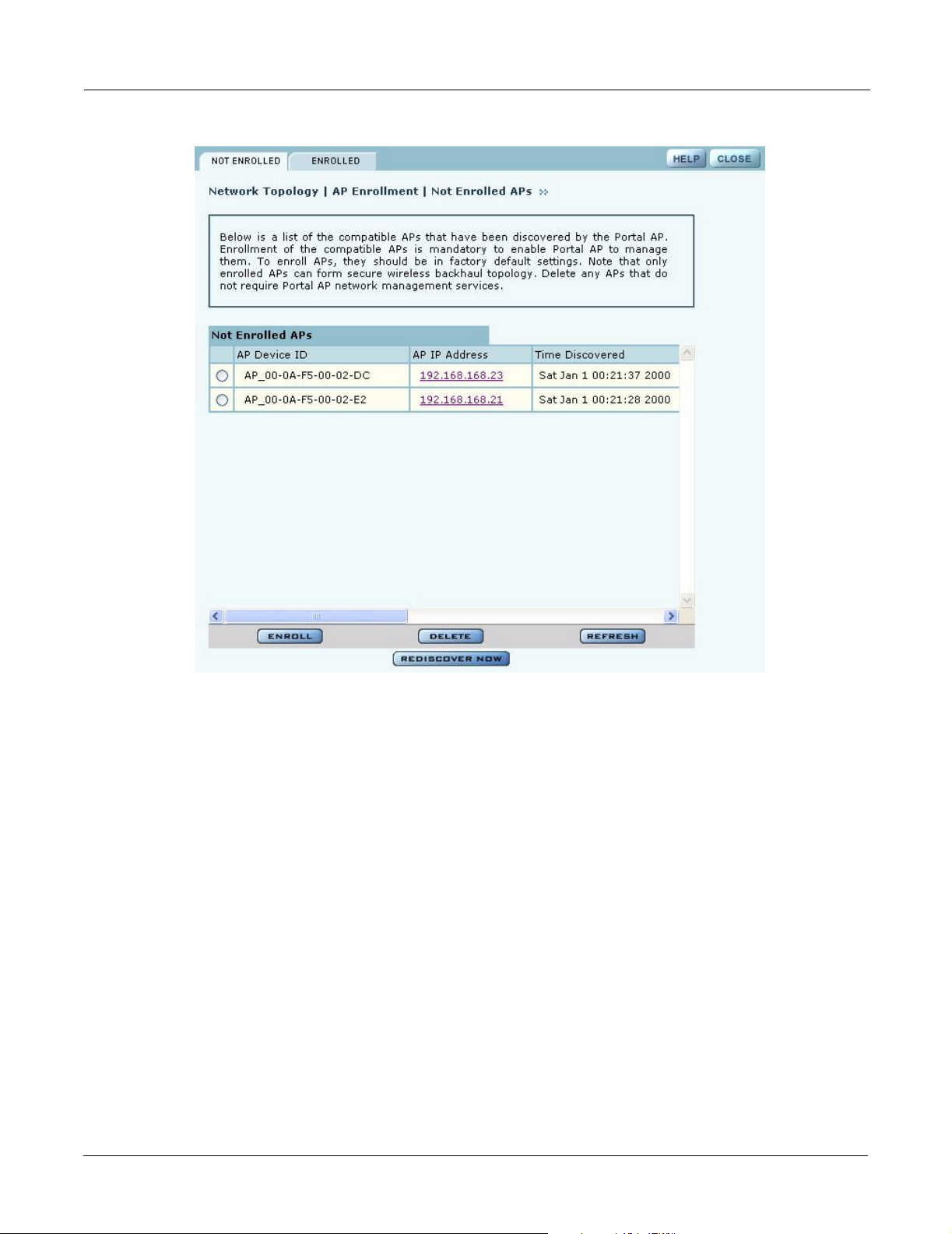
An NM Portal can discover up to 50 APs across multiple IP subnets, but can only enroll up to 20
APs. To access the enrollment panel, choose AP Enrollment from the Network Topology menu.
The AP Enrollment panel opens to display the list of discovered, but as yet un-enrolled, APs
(Figure 120).
Figure 119: AP Enrollment
NM Portal:
Manage and
Monitor the
Network
Enrollment Portal:
Verify AP Identity
Other APs
A0028A
Installation and Configuration Guide: Airgo Access Point 165
9 Managing the Network
Figure 120: Network Topology - AP Enrollment - Not Enrolled
Perform the following functions from this panel:
Function Description
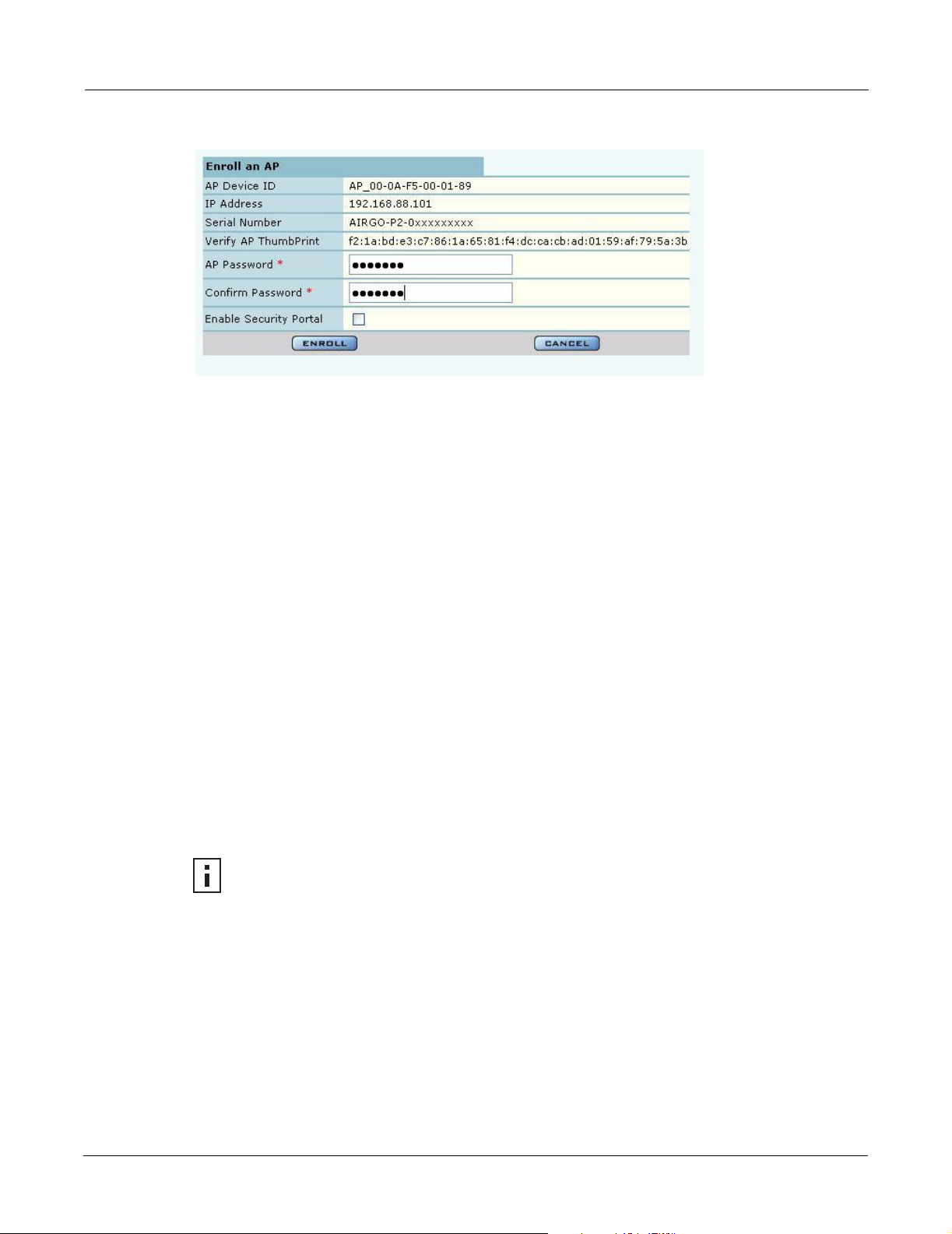
Enroll an AP 1 Select the desired AP, and click Enroll to open the Enroll an AP Entry
panel (Figure 121). If the AP is not in the factory default state, a message is
presented. Click the AP link to open the web interface for the AP and reset
it to the factory default configuration.
2 After verifying the information on the panel (Table 13), enter the correct
password, and click Enroll. It takes a couple of minutes to enroll the AP.
Delete an AP Select an AP and click Delete to remove it from the list.
Refresh Click to update the display.
Rediscover Now Scan the network to discover APs and update the Not Enrolled APs table.
166 Installation and Configuration Guide: Airgo Access Point
Using the Network Topology Menu
Figure 121: Network Topology - AP Enrollment - Enroll an AP Entry Panel
The Enroll an AP panel contains information that uniquely identifies the AP. To verify the identity
of the AP, compare the following information to the information on the paperwork shipped with the
AP:
Table 13: AP Enrollment Information
Field Description
AP Name Verify the alphanumeric name of the AP. The default is the IP address.
IP Address Verify IP address of the AP.
Serial Number Verify the AP serial number.
Thumbprint Verify the thumbprint, which uniquely identifies the AP for security purposes.
Password Enter and confirm the Airgo-supplied password.
Security Portal Indicate whether to use the AP as a standby security portal. With a backup
security portal, a copy of the user authentication database remains accessible
even if the NM Portal AP becomes unavailable.
When an AP is enrolled, it is configured with the enrolling AP’s bootstrap configuration. Refer to
Chapter 3, “Installing the Access Point,” for bootstrap configuration details.
Enrolled APs
Enrolled APs are listed on the Enrolled tab of the Enrollment panel (Figure 122). The screen should
refresh automatically to reflect new enrollments. If this does not happen, click Refresh.
NOTE: If DHCP is used for address assignment for enrolled Airgo APs, the AP
address may change periodically. When that occurs, there is no interruption to service,
and all security credentials remain intact.
Installation and Configuration Guide: Airgo Access Point 167
 Loading...