

Page 1
Placentia, California
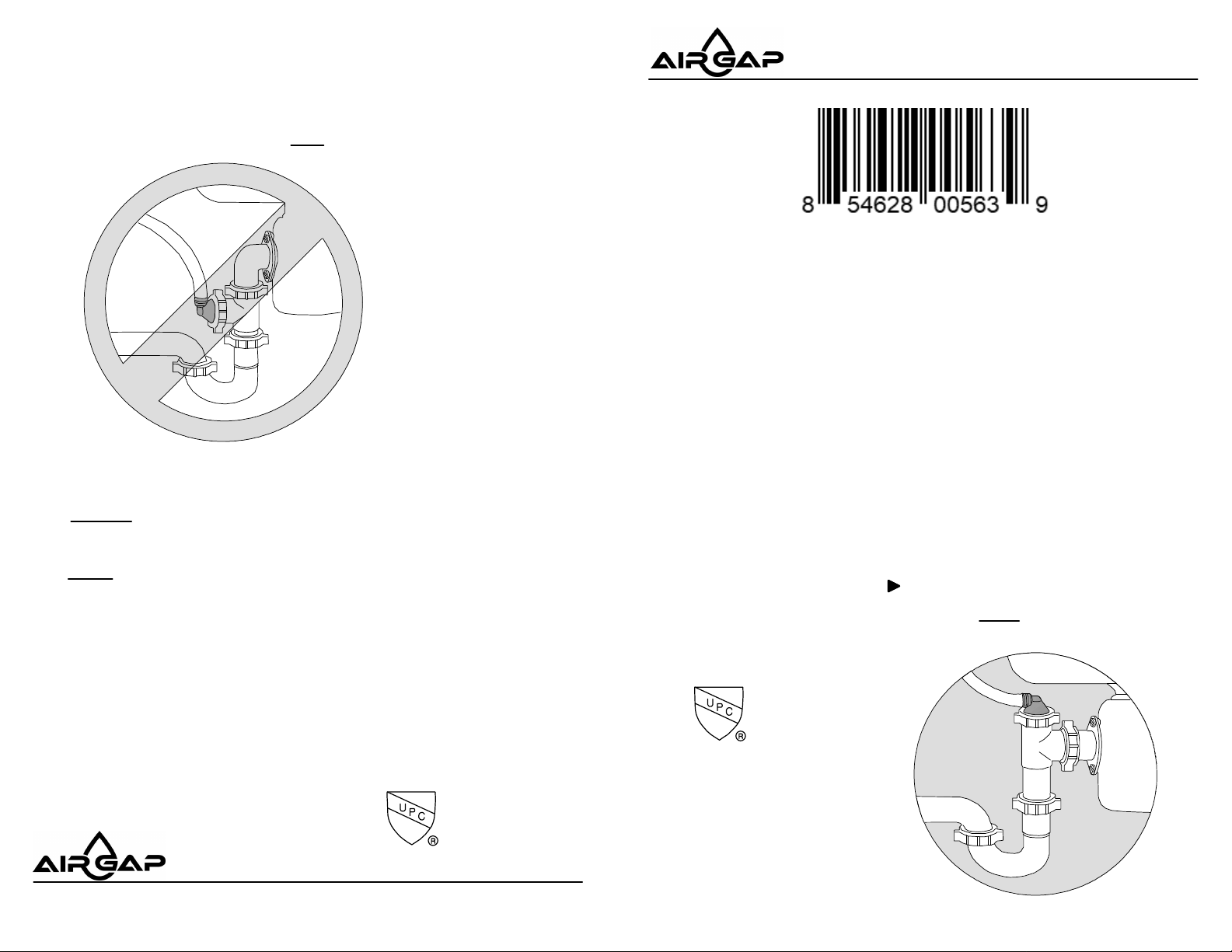
CONFIGURATION – B
For best results, use Configuration – A only
CONFIGURATION-B
CAUTION: Be careful not to overtighten any
nuts on plastic fittings.
(Not Recommended)
Model:
ET109-003
REVERSE OSMOSIS
DRAIN LINE ADAPTER
Pat. No. 5,449,456
Pat. No. 5,681,459
Pat. No. 5,944,985
Pat. No. 6,193,879
MADE IN USA
NOTE: To connect reverse osmosis reject
water drain line to the plumbing of a single
compartment sink without disposal, or a
double compartment sink, please request
an ET112-003.
Drain saddle fittings are prohibited in
the United States.
The ET109-003 is designed to be used
downstream of an approved air gap.
MADE IN USA
Serving the
Reverse Osmosis
Water Treatment Industry
Copyright @ AIRGAP INTERNATIONAL a Division of Altinex Inc.
500 S Jefferson Street, Placentia CA 92870 USA • 949-955-3928 • Email: [email protected]
ASTM F 409
ASTM F 409
Old Part Number:
9-50B
DLA-9
Doc. # 400-0723-003
TM
For Single Compartment
Sink with Disposal
Page 2
Installation Procedures
For Single Compartment Sink with Disposal
LIST OF PARTS ENCLOSED
1 – Drain Line Adapter with 1/2-inch Barb Connection ..............
1 – Disposal (Baffle) Tee...........................................................
1 – Flanged Tailpiece....................................................................
2 – Slip Joint Wing Nuts........................................................
2 – Slip Joint Beveled Washers...............................................
• The ET109-003 converts the plumbing of a single sink/disposal installation to
receive the reject water from an under-counter reverse osmosis appliance.
• To install the ET109-003 reverse osmosis reject water Drain Line Adapter,
follow these instructions.
CONFIGURATION – A (Recommended)
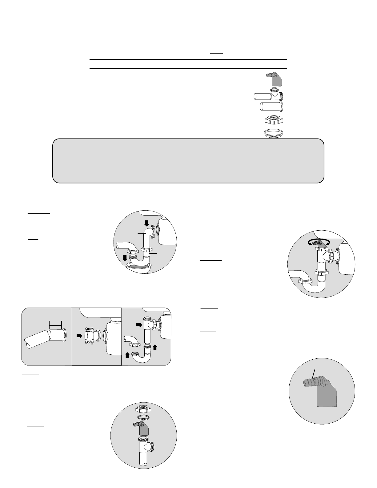
1. Remove disposal ell and J-bend
from disposal and trap. Use a bowl
to catch trap water. (See Fig. 1)
2. Cut new flanged tailpiece
(provided) leaving approximately
1-1/2 to 2 inches from the flange, so
that when positioned between
disposal and disposal tee
(provided), the tailpiece of the tee
will line up and insert into J-bend of
a trap. (See Figs. 2a & 2c)
Always ensure that tube ends are cut squarely and
inserted into the bottom of all slip joint sockets.
1 1/2 - 2"
Disposal
Ell
Trap
ET109-003
5. Mount gasket end of the cut tailpiece to disposal in the
reverse order that disposal ell was removed (See Fig. 2b).
Then install side outlet of disposal tee
securely onto the cut end of tailpiece with
S.J. washer and wing nut (provided).
(See Fig. 2c)
J-bend
FIG. 1
6. Replace J-bend by sliding onto
trap and tailpiece of disposal tee
simultaneously. Secure tightly by
reusing original S.J nuts and
washer. (See Fig. 2c & 4)
7. Rotate barb connector towards incoming reject water drain
tubing and secure tightly with the wing nut. (See Fig. 4)
FIG. 4
FIG. 2a FIG. 2b FIG. 2c
NOTE: in some cases, it may be necessary to rotate the
disposal and J-bend to gain the distance required to line up
the new disposal tee. To do this, loosen the disposal locking
ring, turn disposal as desired, then tighten.
3. Reuse rubber gasket from disposal
ell by mounting on the flange of the
new tailpiece. (See Fig. 2b)
4. Insert a new drain line adapter
with barb (provided) into the top
of the disposal tee until it firmly
seats on the bottom of the
socket. Gently secure with
slip-joint washer and wing nut
(provided). (See Fig. 3)
FIG. 3
8. Insert 1/2-inch drain tubing over the barb connector
to complete the installation.
IMPORTANT:
• Use only high quality 1/2-inch
tubing and roundness with no
surface
nicks or scratches.
• Always make a clean square cut if
necessary, using a plastic
tubing cutter or sharp razor knife.
CAUTION:
• For a leak-free connection, the tubing
must sit fully up to the third barb.(See Fig. 5)
• Check that connection is leak free.
-OVER-
Third Barb
FIG. 5
 Loading...