

Airflow Systems V410 Owner's Manual
The Local Exhaust & Ventilation Company Inc.
22-1050 Brock Rd, Pickering, Ontario L1W 3X4
Tel: 905.831.7001 Fax: 905.831-7443
E-mail: sales@lev -co.com Web Site: www.lev-co.com
Toll Free: 1.888.862.5356
OWNERS MANUAL
MODEL V410
(INCLUDES VIBRAPULSE CLEANING SYSTEM*)
• INTRODUCTION
• SPECIFICATIONS
• UNPACKING
• INSTALLATION
• MOUNTING
• ELECTRICAL
• OPERATION
• MAINTENANCE
• TROUBLESHOOTING
• REPLACEMENT PARTS
• MOTOR TROUBLE GUIDE
***IMPORTANT***
THIS MANUAL CONTAINS PRECAUTIONARY STATEMENTS RELATING TO WORKER SAFETY. READ AND
SAVE THIS MANUAL COMPLETELY AND COMPLY AS DIRECTED. ALL THE POTENTIAL HAZARDS OF DUST
AND MIST CONTROL SYSTEMS AND EQUIPMENT ARE IMPOSSIBLE TO LIST; THEREFORE, OBTAIN THE
SERVICES OF A PROFESSIONAL INSTALLER. A FIRE PROTECTION EXPERT SHOULD BE OBTAINED IN THE
EVENT THE PRODUCT IS INTENDED FOR USES WHICH PRESENT A POTENTIAL RISK OF FIRE OR FIRE
PROPAGATION. REFER TO APPROPRIATE AUTHORITIES, AND DISCUSS YOUR INTENDED USE WITH YOUR
LOCAL DISTRIBUTOR OR AIRFLOW SYSTEMS, INC. WORKERS HANDLING EQUIPMENT OR SYSTEMS
SHOULD BE INSTRUCTED TO CONDUCT THEMSELVES IN A SAFE MANNER.
PART # 4KT11067 (REV 4/99/-/#32-2142)
*PATENT APPLIED FOR
3
ALWAYS USE AIRFLOW SYSTEMS, INC. REPLACEMENT PARTS AND FILTERS TO
MAINTAIN WARRANTY.
TO ORDER SPARE PARTS CONTACT:
The Local Exhaust & Ventilation Company Inc.
22–1050 Brock Rd, Pickering, Ontario L1W 3X4
Tel: 905.831.7001 Fax: 905.831.7443
Toll Free: 1.888.862.5356
E-mail: sales@lev -co.com Web Site: www.lev-co.com
4

TABLE OF CONTENTS
1. Safety.............................................................................................................................. 4
2. Airflow Systems Sets the Standard............................................................................... 5
3. Specifications.................................................................................................................. 6
4. Inspection....................................................................................................................... 7
5. Preparation and Installation.......................................................................................... 7
6. Compressed Air Supply................................................................................................. 7
7. Vibra Pulse
Filter Cleaning System............................................................................. 7
8. Electrical......................................................................................................................... 8
Three phase............................................................................................................ 8
9. Operation........................................................................................................................ 9
10. Maintenance................................................................................................................... 10
Vibra Pulse
System - Hose Replacement......................................................... 10
11. Filter Service.................................................................................................................. 13
Filter Replacement/Removal for Cleaning.......................................................... 13
Filter Cleaning - Vibra Pulse
System................................................................. 14
HEPA Filters ......................................................................................................... 15
AD Module............................................................................................................ 15
12. Other Service ................................................................................................................. 15
13. Replacement Parts......................................................................................................... 16
14. Troubleshooting.............................................................................................................. 18
15. Notes............................................................................................................................... 19
16. Appendix......................................................................................................................... 20
5

READ THIS MANUAL CAREFULLY BEFORE ATTEMPTING TO INSTALL OR OPERATE
THE MODEL V410 UNIT. RETAIN THESE INSTRUCTIONS FOR FUTURE REFERENCE.
SAFETY RULES
Follow all electrical and safety codes as well as the National Electrical Code (NEC), National Fire
Protection Association (NFPA), and the Occupational Safety and Health Act (OSHA). All electrical
connections and wiring should be performed by qualified personnel only.
National Fire Protection Association (NFPA) standards require specific duct design and dust collector
configuration when collecting potentially reactive metal dusts, such as aluminum and magnesium, and other
materials. NFPA also covers other dusts such as grain, plastics, etc. A guideline for determining the
precautions to be taken can be found in NFPA 497. Other NFPA standards may apply to your specific
application. Consult current NFPA standards, available from NFPA, 1 Batterymarch Park, Quincy, MA,
02269, 1-800-344-3555, for applicable safeguards whic h may required for the Installation, Operation, and
Service of this product. Fire suppression equipment provided by others.
Additional references are the Uniform Building Code and Uniform Mechanical Code.
WARNING
APPLICATION OF DUST CONTROL EQUIPMENT:
1. Do not mix materials being collected by a dust collector unless it is determined that mixing of materials
does not cause hazardous conditions to occur or creates a condition of operation for which the equipment
was not intended.
2. Under no condition should burning cigarettes or any burning object be allowed into the hood or ducting of
any dust control system.
3. When dust collectors are used to collect emissions from steel or combined metal sanding, the dust
collector should be located an adequate distance away to minimize the chance of ignition of duct system
residue from hot metal chips and sparks. Should further protection from fire be required, adequate duct
systems from capture hoods and dust collector should be provided so that a fire protection specia list can
install extinguishing equipment. You may also want to contact your insurance underwriter.
4. Explosion relief vents may be required per NFPA codes. Explosion vents are used to minimize the
destructive effect of an explosion and are intended primarily to protect from injury anyone in the
immediate area of the collector. Damage to the collector may, or may not, be repairable. Vents installed
on dust control equipment within a building must be vented to the outside to minimize chances of injury to
persons or a secondary explosion. Again, consult the proper authority to determine proper method of
venting. Explosion relief vents are optional and should be ordered with the dust collector or installed
locally.
6

5. Always disconnect unit from power source before inspecting or servicing.
AIRFLOW SYSTEMS SETS THE STANDARD
The Airflow Systems Model V410 collects dust, welding smoke, and other dry pollutants in industrial
plants, shops, schools and factories. The general theory of operation is that air bearing pollutants passes
through the inlet and must make a 180o turn to pass through a spark screen where large particles fall out of
the air stream. The particulate laden air then passes through the (2) main 95% cartridge filters where the +1
and sub-micron particles are captured. The main filters have 150 ft2 collection area each for maximum
intervals between service. The Vibra Pulse is for filter cleaning with dry dust applications. After passing
through the filters, the cleaned air is then discharged thru the top of the unit. Figure 1 shows general
construction details.
The Model V410 is a complete portable collector. The unit comes equipped with four 5" industrial duty
casters (2 swivel, 2 fixed). It comes standard with (2) 3” FPT couplings for attachment of collection hoses.
The Model V410 can be mounted in a stationary location if desired by ordering it with the optional hopper
and stand kit.
The Model V410 is available with an external 99.97% HEPA filter or Adsorption Module (AD) if
required.
7
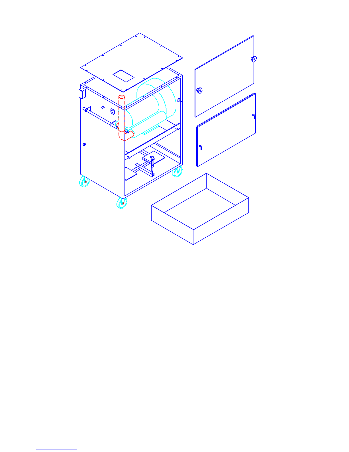
Figure 1.
8
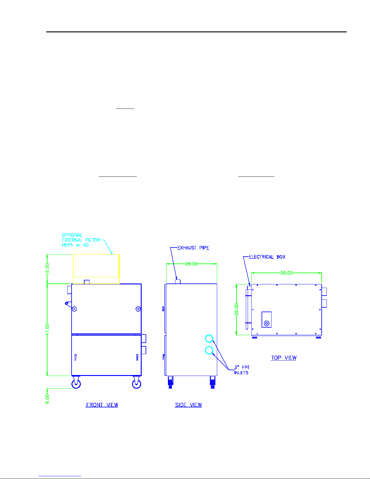
SPECIFICATIONS(*): MODEL V410
STD DIM: 36" W x 26" D x 53" H [0.91m W x 0.66m D x 1.35m H]
WEIGHT: 680 lb. (STD) [309 kg]
CONSTRUCTION: 12 gauge welded zinc coated steel cabinet, finished with a two part chemical and oil
resistant paint. Includes separate filter and blower access doors, dust pan, and 5" casters.
NOISE LEVEL: 10 HP
STD 76 dBA @ 5’
72 dBA @ 5' w/optional silencer
ELECTRICAL:
Standard Blower Motor: 10 HP [7.46 kW] TEFC BB motor 3450 RPM, 208-230/460/3/60 @ 27.3-25/15 A
FILTRATION:
STANDARD OPTIONAL
1st Stage: 16” Dia CLEAN 2 cartridge filter* 16” Dia Fiber Dust cartridge filter*
2nd Stage: External HEPA/AD Module
(Adds 15” to overall height)
AutoClean
* ASHRAE 52-76 Test Method
(*) AFS has a policy of continuous research and improvement, and reserves the right to change design and specifications without notice.
9
Figure 2.

INSPECTION AND UNPACKING
Inspect your AFS unit for shipping damage immediately upon receipt. Damaged carton(s), broken
crate(s), etc. are indications that the unit may have been damaged in shipment. It is also possible shipping
damage may be concealed and not noticed until the unit is installed and in operation. If any damage is found,
notify your delivery carrier at once and enter a claim. Claims must be filed within 15 consecutive days of
receipt of shipment. FREIGHT DAMAGE CLAIMS ARE THE RESPONSIBILITY OF THE
PURCHASER, NOT AIRFLOW SYSTEMS.
PREPARATION AND INSTALLATION
After initial inspection for shipping damage, check the cabinet filter and motor/blower compartments for
any packing materials and remove. Install casters, then stand unit upright and attach pickup hoses to 3" inlets.
Use correct lifting devices to prevent damage or injury. Roll unit to the desired location. When
using an extension cord with a portable air cleaner, refer to the Appendix and Motor
Troubleshooting Guide Table A for the correct wire gauge.
The following section discusses both physical installation and electrical tie in. Fire suppression
equipment provided by others.
COMPRESSED AIR SUPPLY
Effective cleaning of the filters in most applications will occur when the pressure at the compressed air
connection of the air cleaner is maintained, while the filter is cleaning, of 80 PSI. Pressure over 100 PSI is
NOT recommended at any time, and generally reduces cleaning performance. A pressure below 70 PSI may
decrease cleaning effectiveness in some applications. A nominal ( OFF or not cleaning ) pressure setting of
80 PSI is usually adequate when using a 3/8” compressed air supply line.
If optional regulator/gauge is installed, set regulator to 80 PSI. When air valve is open, confirm pressure
on gauge does not go below 70 PSI.
Compressed air filter provided by others.
Fire suppression equipment provided by others.
VIBRA PULSE
FILTER CLEANING SYSTEM
To set up the Vibra Pulse system, simply slide the 3/8” air hose over the hose barb fitting on the outside of
the cabinet and secure it with the 1” hose clamp. Refer to Figure 3. Use any standard Quick Disconnect 3/8”
fitting (as used on an air tool) to attach to the supply air. The V410 unit comes with 10’ of 3/8” air line. If a
longer run of hose is required, it is recommended to use a continuous piece of
hose to avoid splicing, as this will reduce the compressed air available to the
unit. Always use 3/8” air line with this unit. Once the air is attached to the
unit, set the line pressure to 80 PSI (see Compressed Air Supply section). It is
recommended to use a separator/drier on the air line to prevent any debris
from fouling the actuator valve. Compressed air filter provided by others.
Test the system by pressing and pulling the actuator valve on the side of the
10
unit (See the MAINTENANCE Section for more details). If any problems are found, consult the
TROUBLESHOOTING Section in this manual.
ELECTRICAL
All 3 phase AC Model V410 units have wiring terminated inside the junction box located on the side of the
unit. Motor starters and disconnects are not supplied with the unit (unless purchased as an option), and must
meet local and National Electrical Code. Motors are typically multiple voltage type (e.g. 208/230/460). Make
sure connections in motor junction box correspond to the line voltage you plan to use. Thr ee phase motor
starters (manual or magnetic type) must have properly sized thermal overloads for the voltage and current
required at the motors.
All units are required to have a motor voltage and current check performed at startup. Motor checkout
should be performed with the unit running, all filters in place and cabinet doors closed. Measured motor
current readings should be equal to or below motor nameplate rating. These specifications can be
found on the motor name plate or in the specifications section of this manual. If the motor amp draw does not
fall within the Full Load Rating (FLA) refer to the TROUBLESHOOTING Section of this manual.
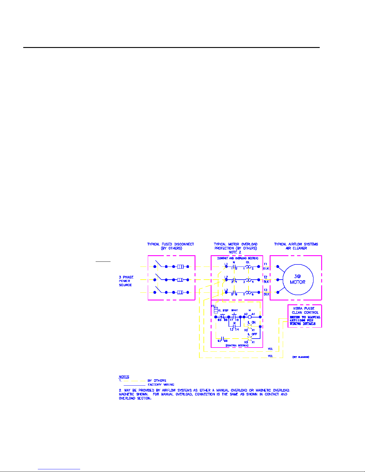
THREE PHASE MOTORS
Three phase motors do not have overload protection included in the standard configuration and must be
supplied by the end user, see Figure 4 or page A3 of the Appendix. They are also available from the factory
as a pre-installed option. If these protective circuits are not ordered from the factory, use equipment as
specified by the National
Electric Code or other
applicable authority.
On the three phase models,
the motor can operate in either
direction, and the fan will pump
air in either direction. However,
for proper suction and airflow,
the blower motor should be
turning in a manner such as to
create a suction at the (2) 3”
inlets. To verify the correct
rotation, bump start motor (turn
on briefly then turn off) and feel
the 3” inlet coupling on side of
unit. There should be a suction.
If air is blowing out, reverse any
two wires of the in-coming
power and motor will reverse
direction (3 PHASE ONLY).
Figure 5 shows details on
changing the wiring
configurations. The main power
Figure 4.
leads, L1, L2, and L3 are not
differentiated by color. If motor rotation must be changed, then reversing any two of the leads will produce
this result (e.g. reverse. L1 and L2 or L2 and L3). Figure 6 shows the voltage configuration hook-ups on the
A2

three phase motor. Consult the motor name plate and verify the line input voltage before attempting
to make this change.
Figure 5.
Figure 6.
CAUTION
IN LARGE PLANTS, WHEN ROLLING UNIT FROM ONE BUILDING TO
ANOTHER, YOU MAY BE ON A DIFFERENT SUBSTATION TRANSFORMER.
UNITS USING A THREE PHASE BLOWER MOTOR MAY RUN BACKWARDS.
CHECK ROTATION IN EACH LOCATION WHERE THE UNIT WILL BE USED
TO ENSURE THAT BLOWER MOTOR ROTATES IN PROPER DIRECTION.
REVERSING SWITCHES ARE AVAILABLE IF REQUIRED.
CAUTION
CABINET DOORS MUST BE CLOSED WHEN OPERATING THE BLOWER.
MOTOR WILL BE OVERLOADED IF RUN WITH THE FILTER DOOR OPEN.
OPERATION
Operation of the Model V410 is very straight forward. Roll the unit to the desired work area and arrange
it so that no equipment will come into contact with the unit. Simply switch the unit ON when smoke or dust
collection is required. Remember to always turn the unit OFF when cleaning the filters.
DO NOT OVER-EXTEND THE UNIT POWER CORD REACH.
DISCONNECTING THE POWER SOURCE WHILE UNIT IS IN OPERATION
CAN CAUSE SPARKING.
WARNING
A3

MAINTENANCE
WARNING
ALWAYS DISCONNECT THE UNIT FROM THE POWER SOURCE
BEFORE WORKING ON OR NEAR THE MOTOR OR WIRING
ASSEMBLIES. LOCK OUT DISCONNECTS TO PREVENT UNEXPECTED
APPLICATION OF POWER.
The Model V410 comes standard with (2) CLEAN 2 filter cartridges of 150 square feet of media each.
An optional External Module is available for a final filter. This external module can house either a HEPA
filter or an adsorption bank (AD). Filter access is from the top cover of the module.
The Adsorption Module (AD) is a refillable, finely perforated container to hold the adsorption material in
the air flow. As with the HEPA, it is located on top of the unit. The AD utilizes the same mounting method as
described above. The AD module has a 2" 30% poly after-filter to remove any carbon (or other) dust that
occurs from adsorption material breakdown.
VIBRA PULSE SYSTEM MAINTENANCE - HOSE REPLACEMENT
The Vibra Pulse hose that is used to clean the filter will eventually wear out. Check for signs of excessive
wear when doing normal filter service or if a decrease in filter cleaning effectiveness is observed. A hose
should be replaced when it has worn to a length of 6”. Replacement of the hose is a simple operation. With
the unit turned off, disconnect power and lock out. CAUTION: Disconnect Air Supply before working
on unit. Proceed as follows to accomplish the hose replacement.
1. Turn unit off. Disconnect power and lock out.
2. Disconnect air supply before working on unit and lock out.
3. Remove filter access door.
4. Remove cartridge filter(s) from unit.
5. Remove dust tray and dispose of material in accordance with local, state, and federal regulations.
6. The Vibra Pulse actuator mechanism consists of the following:
1 fixed and 3 loose components (per filter), see Figure 7.
a. Fixed component is the 3/8” rigid hose barb attached to the Vibra Pulse
Plenum chamber
b. The loose components involved in the replacement operation consist of:
1 - Reusable spring (7PR1-2004)
1 - Reusable hose clamp (7HG3-1003)
A4
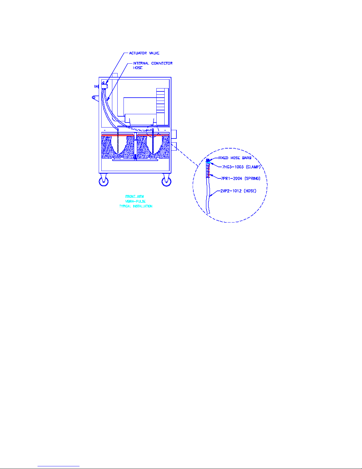
1 - Hose (2VP2-1012), quantity as required by applicable unit (1 hose per cartridge).
Figure 7.
7. Remove the old Vibra Pulse hose. This is done by loosening the hose clamp securing the spring at the
top of the VP hose where the VP hose attaches to the 3/8” hose barb. Slide the spring and hose clamp
down the VP hose and set aside for later use. Next, remove the old VP hose, this is sometimes easiest to
do by cutting the hose at the top, where it fits over the hose barb, to allow free removal. Discard old
hose after removing.
8. Loosely place hose clamp (retained from step above) into the first closed loop of the spring after first
opening clamp to maximum diameter, see Figure 8.
A5
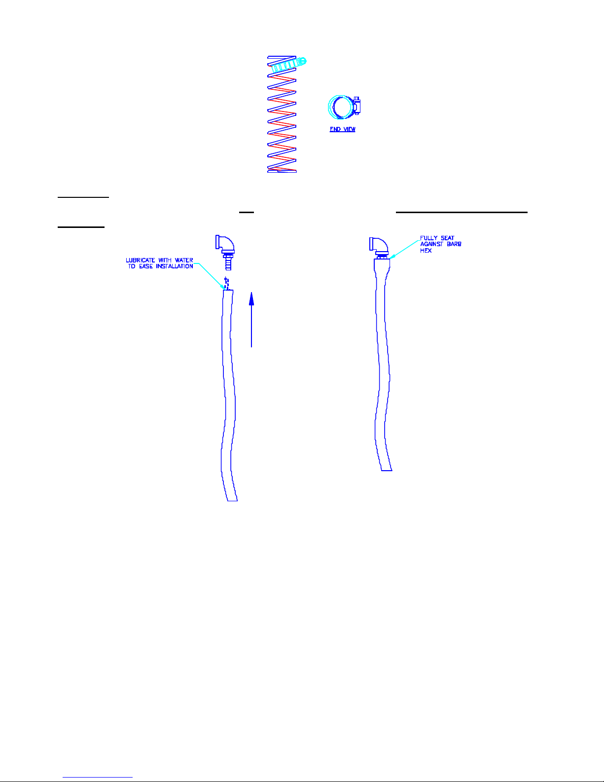
9. Install the new Vibra Pulse hose onto the air cleaner’s hose barb until
fully seated against brass hex on barb, see Figure 9. Lubricate with
water or Windex to ease installation. Do not use oil or grease as
Figure 8.
lubricant!
Figure 9.
A6
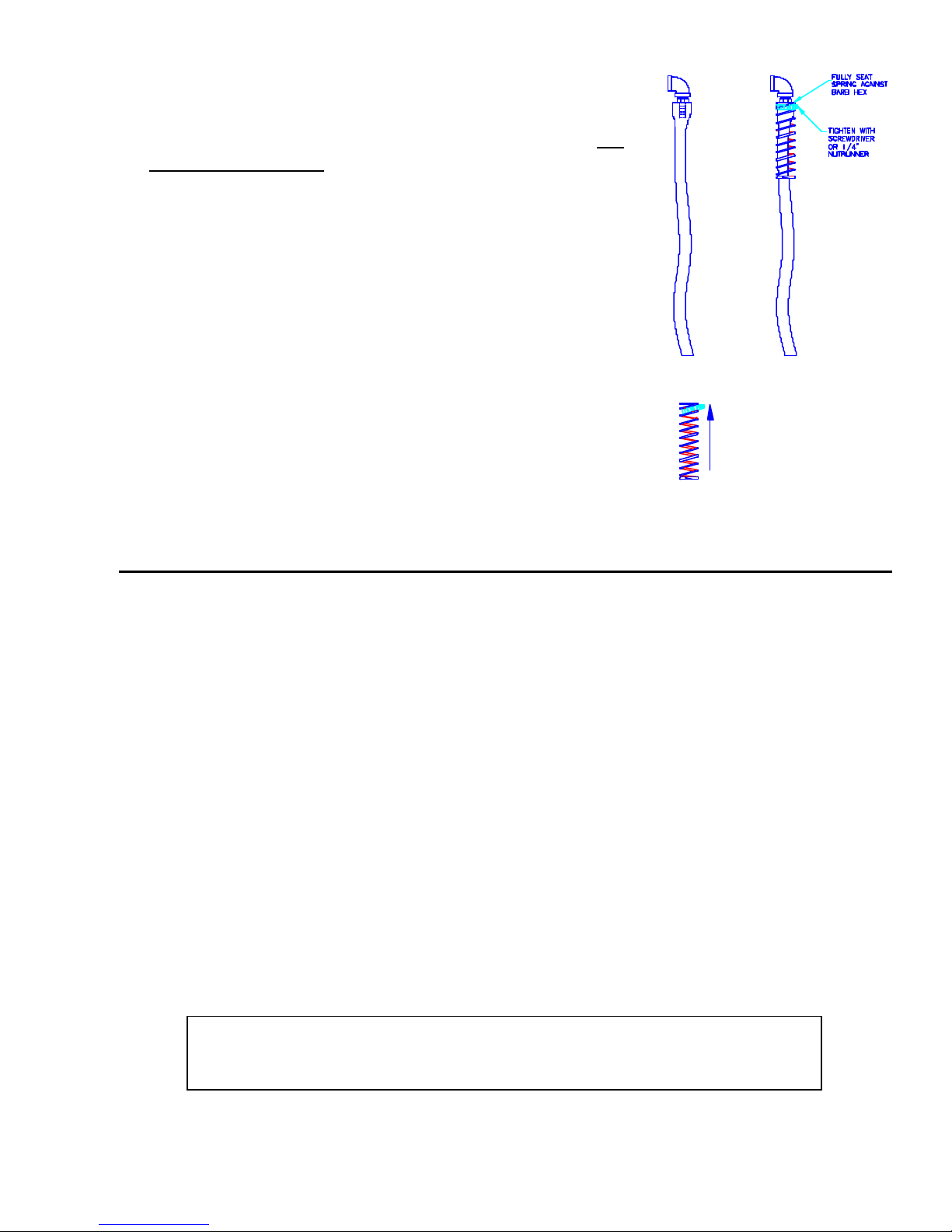
10. Slide the spring/clamp up over the hose and 3/8” hose barb until it
fully seats against the barb’s hex, see Figure 10.
11. Tighten the hose clamp using screw driver or 1/4” nut runner. DO
NOT OVERTIGHTEN!
12. Replace filter(s) into unit. Note: Make sure NOT to pinch hose
- position Vibra Pulse hose into the center of the cartridge
filter. Engage filter mechanism if required.
13. Reinstall dust tray.
14. Reinstall filter access door.
15. Reconnect air line and power.
16. Test the Vibra Pulse system for operation manually or electrically
as appropriate for your unit’s configuration.
Figure 10.
FILTER SERVICE
The filters have been charged with pre-coat (an inert white mineral dust) at the factory. This pre-
coat material will increase initial efficiency and help to extend the cartridge filter life. Upon initial unit start up,
go through one cleaning cycle (see filter cleaning below), most of the pre-coat will be removed from the filter
and fall into the dust pan. The remaining pre-coat will stay on the filters. Save any material that falls into the
pan for treating replacement filters. A Material Safety Data Sheet (MSDS) will be furnished upon request.
Please contact the Airflow Systems Representative or the AFS Factory.
Filter service is required when a reduction of airflow (suc tion) is observed. The optional pressure gauge is
used to judge the amount of particulate collected on the filter. As the worker gets accustomed to the units’
effectiveness of capture, and the associated gauge reading, the gauge can then become an indicator of filter
condition.
The optional pressure gauge is calibrated as follows:
In most applications, with clean filters, turn unit on and mark the pressure reading on the
gauge. Make a second mark at 2.0" higher than initial reading (i.e. if initial reading is 3.0" the
second mark should be at 5.0"). Note that a reading of 5.0” is typical of when the filter should
be cleaned in most applications.
NOTE
Unit can continue to run safely beyond the 5.0 " pressure differential recommended,
however performance will be reduced. Exceeding 6.0" pressure differential across the
filter may cause reduced filter life.
A7
FILTER REPLACEMENT/ REMOVAL FOR CLEANING
1. Turn unit OFF and disconnect from power source.
2. Remove filter access panel.
3. Release filter retaining latch located between cartridges,
(see Figure 11.) This will lower the filter holding frame.
Unhook latch to let holding frame rest at lowest position.
4. Remove filters, being careful not to damage the Vibra
Pulse hose which hangs suspended in the center of each
filter.
5. To replace, reverse above procedure. Avoid inadvertently
trapping the Vibra Pulse hose between filter end cap and
cabinet. Also, make certain that the filters are not cocked.
(A cocked filter will not properly seal to the blower inlet,
resulting in significant contaminant by-pass.)
Figure 11.
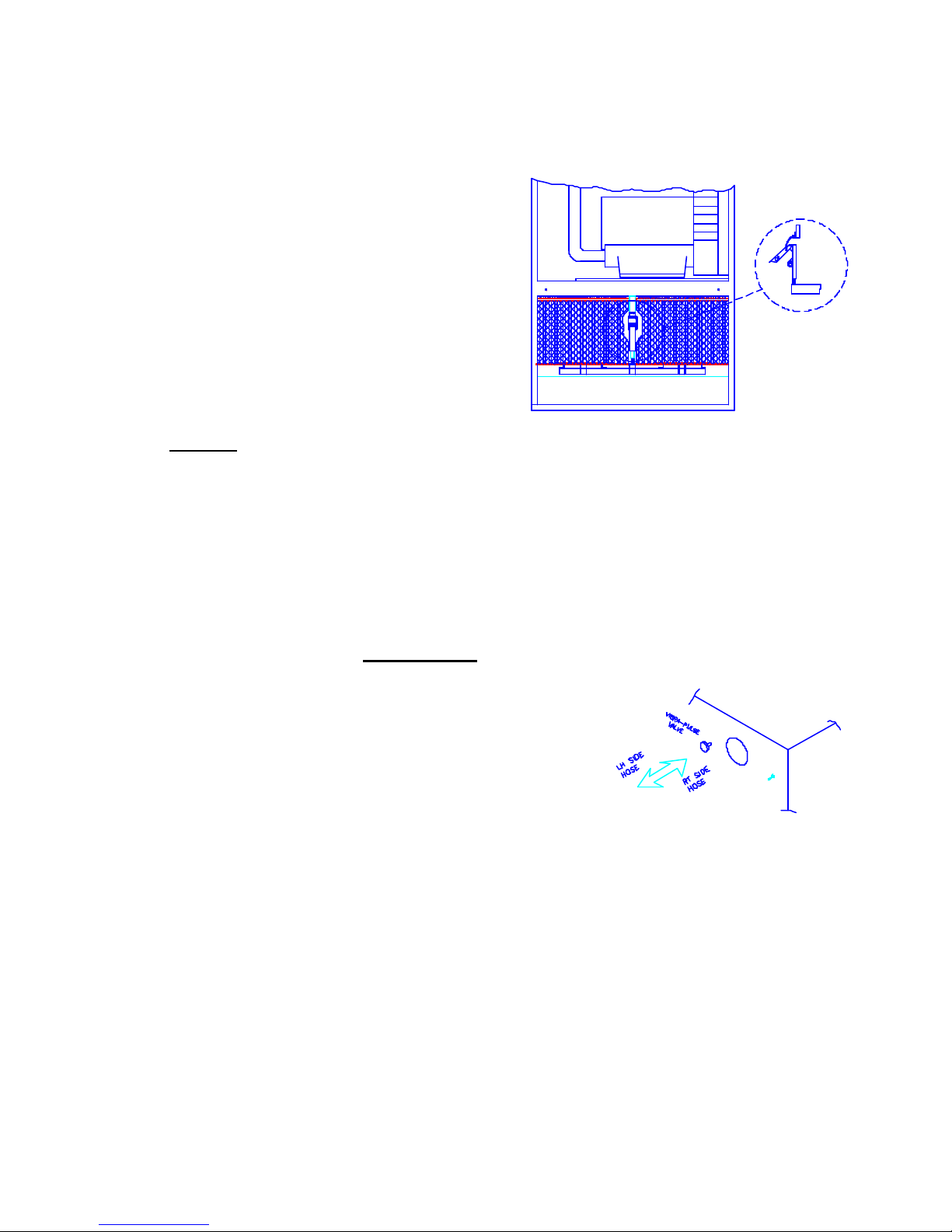
FILTER CLEANING - VIBRA PULSE SYSTEM
1. Turn unit OFF and let motor/blower come to a complete stop.
2. Connect the 3/8” airline (supplied) to REGULATED shop air (80 PSI, see Compressed Air Sup ply
section). Compressed air filter provided by others.
3. PRESS and hold the pulse cleaning button in for 5 - 10 seconds. Next,
PULL the button outwards for 5 - 10 seconds. This will clean the other
side of the filter. Repeat this process 2 or 3 times. See Figure 12.
4. Open the filter access door. Remove and empty the dust tray in the
bottom of the unit. This will prevent the dust from recollecting on the filter
when the unit is restarted. Close door.
5. Turn the unit ON and check suction and/or pressure gauge. If additional
cleaning is needed repeat the steps listed above. (During multiple
cleanings, some dust may come out of the hose or blower outlet.
Figure 12.
This is normal.)
6. If the filters are overloaded, in-place cleaning may not dislodge all of the collected dust. The filter will need
to be removed and tapped out in the dust pan or replaced with a new filter. DO NOT BLOW OFF
WITH COMPRESSED AIR DUE TO POSSIBLE OVER-EXPOSURE OF WORKERS AND
POTENTIAL FILTER DAMAGE.
7. Any moisture such as oil or water on the filter will cause shortened filter life. If the filters plug with dirt
due to oil or water, they may not pulse clean. (See Note below.)
8. If shop air is not clean and dry it may be necessary to install an airline filter/drier to prevent premature filter
replacement.
CAUTION
A8
 Loading...