

Airflow Systems IAQ50 User Manual
OWNER’S MANUAL
Indoor Air Quality
Meter
Model IAQ50

LIMI TATIO N OF WARRANTY AND LIABILITY
Seller warrants the goods sold hereunder, under normal use and service as described
in the operator's manual, shall be free from defects in workmanship and material for
twenty-four (24) months, or the length of time specified in the operator's manual, from
the date of shipment to the customer. This warranty period is inclusive of any statutory
warranty. This limited warranty is subject to the following exclusions:
a. Hot-wire or hot-film sensors used with research anemometers, and certain other
components when indicated in specifications, are warranted for 90 days from the
date of shipment.
b. Parts repaired or replaced as a result of repair services are warranted to be free
from defects in workmanship and material, under normal use, for 90 days from
the date of shipment.
c. Seller does not provide any warranty on finished goods manufactured by others or
on any fuses, batteries or other consumable materials. Only the original
manufacturer's warranty applies.
d. Unless specifically authorized in a separate writing by Seller, Seller makes no
warranty with respect to, and shall have no liability in connection with, goods
which are incorporated into other products or equipment, or which are m odif ied b y
any person other than Seller.
The foregoing is IN LIEU OF all other warranties and is subject to the LIMITATIONS
stated herein. NO OTHER EXPRESS OR IMPLIED WARRANTY OF FITNESS FOR
PARTICULAR PURPOSE OR MERCHANTABILITY IS MADE.
TO THE EXTENT PERMITTED BY LAW, THE EXCLUSIVE REMEDY OF THE USER
OR BUYER, AND THE LIMIT OF SELLER'S LIABILITY FOR ANY AND ALL
LOSSES, INJURIES, OR DAMAGES CONCERNING THE GOODS (INCLUDING
CLAIMS BASED ON CONTRACT, NEGLIGENCE, TORT, STRICT LIABILITY OR
OTHERWISE) SHALL BE THE RETURN OF GOODS TO SELLER AND THE
REFUND OF THE PURCHASE PRICE, OR, AT THE OPTION OF SELLER, THE
REPAIR OR REPLACEMENT OF THE GOODS. IN NO EVENT SHALL SELLER BE
LIABLE FOR ANY SPECIAL, CONSEQUENTIAL OR INCIDENTAL DAMAGES.
SELLER SHALL NOT BE RESPONSIBLE FOR INSTALLATION, DISMANTLING OR
REINSTALLATION COSTS OR CHARGES. No Action, regardless of form, may be
brought against Seller more than 12 months after a cause of action has accrued. The
goods returned under warranty to Seller's factory shall be at Buyer's risk of loss, and
will be returned, if at all, at Seller's risk of loss.
Buyer and all users are deemed to have accepted this LIMITATION OF WARRANTY
AND LIABILITY, which contains the complete and exclusive limited warranty of Seller.
This LIMITATION OF WARRANTY AND LIABILITY may not be amended, modified or
its terms waived, except by writing signed by an Officer of Seller.
Service Policy
Knowing that inoperative or defective instruments are as detrimental to TSI as they
are to our customers, our service policy is designed to give prompt attention to any
problems. If any malfunction is discovered, please contact your nearest sales office or
representative, or call Customer Service department at +44 (0) 149 4 459200 (UK),
(800) 874-2811 (USA), or (1) 651-490-2811 (International).
ii

Table of Contents
LIMITATION OF WARRANTY AND
LIABILITY................................................................... ii
SECTION 1 General Description .................................5
SECTION 2 Safety...........................................................6
SECTION 3 Setting-Up ..................................................7
Supplying Power to the Model IAQ50 .....................7
Installing the Batteries................................................. 7
Using the Optional AC Adapter ................................7
Start up Sequence for the Model IAQ50...................8
Battery Percentage...................................................8
Log Percentage......................................................... 8
Baud Rate..................................................................8
Setting the Real-Time Clock...................................8
Barometric Pressure ................................................9
Using the Sensing Probe ...........................................10
SECTION 4 Detailed Operation.................................10
Keypad Functions ......................................................10
ON/OFF Key .........................................................11
CO
Key ...................................................................11
2
TEMP Key...............................................................12
HUMID Key ...........................................................13
READ/ENTER Key...............................................13
TIME LOG Key ......................................................14
NEXT TEST Key.....................................................16
%OA (Percent Outside Air) Key .........................16
BP Key .....................................................................21
RECALL Key ..........................................................22
Arrow Keys (56).................................................23
DEL Key ..................................................................24
Printing Data Using the Optional MicroPrinter ...25
Connecting the Optional MicroPrinter...................25
3

SECTION 5 Maintenance ............................................ 26
Probe Tip..................................................................... 26
Cases ............................................................................ 27
Storage......................................................................... 27
SECTION 6 Service and Calibration ........................ 27
Factory Calibration.................................................... 28
Field Calibration ........................................................ 29
Field Calibration Procedure ............................ 29
CO
2
Temperature and Humidity Calibrations
Adjustment Procedure.............................................. 32
SECTION 7 Troubleshooting ..................................... 34
SECTION 8 DIP Switch Settings............................... 36
Specifications................................................................. 38
4

SECTION 1
General Description
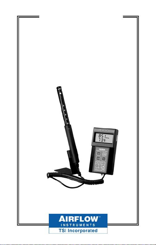
The Model IAQ50 measures Carbon
Dioxide (CO
relative humidity, and calculates dew
point and wet bulb. It also calculates the
percentage of outside (make up) air in a
given indoor space, using CO
temperature. The instrument will determine statistics and recall individual data
points for up to 255 test IDs. The Model
IAQ50 will retain data even after it is
turned off.
The IAQ50 ships in a soft-sided carrying
case that holds the meter and probe, a
probe stand, and calibration collar. There
is space in the case for an optional MicroPrinter and charger. The instrument ships
with batteries (which are not installed), a
calibration sheet, and this Owner’s
Manual.
) level, temperature and
2
levels, or
2
5

SECTION 2
Safety
When using the IAQ50 to check for CO
temperature or humidity values, make
certain that you can safely raise and hold
the instrument while making measurements. Be especially careful when working
on a ladder.
Observe all necessary precautions so that
the unit does not become caught in
moving machinery or touch any exposed
electrical wiring.
DANGER!
Use with corrosive or other dangerous or
explosive gas mixtures is not recommended.
WARNING!
Do not expose the sensing probe to
excessive heat—it can damage the
sensors and probe.
2,
6

SECTION 3
Setting-Up
Supplying Power to the Model IAQ50
The Model IAQ50 can be powered in one
of two ways: four AA-size batteries or an
optional AC adapter.
Installing the Batteries
Insert four AA batteries as indicated by the
diagram located on the inside of the
battery compartment. The Model IAQ50 is
designed to operate only with alkaline
batteries, which are included. At 15%
battery life remaining, the battery indicator will show that the batteries need to be
changed.
Using the Optional AC Adapter
The optional AC adapter allows you to
power the Model IAQ50 from an AC
outlet. When using the AC adapter, the
batteries (if installed) will be bypassed.
The AC adapter is NOT a battery charger.
7

Start up Sequence for the Model IAQ50
When the instrument is turned on, all
segments of the display will light up and
then the meter goes through a start-up
sequence.
Battery Percentage
This shows the remaining amount of
battery power.
Log Percentage
This shows how much of the datalogging memory is still available.
Baud Rate
The Model IAQ50 has a DEFAULT baud
rate of 1200, which allows it to communicate with the optional portable MicroPrinter.
Setting the Real-Time Clock
The Model IAQ50 has an internal clock
that keeps track of the time (the format
is HH.MM where HH is the hour in 24hour format and MM is minutes) and
the date. It is very important to set the
time and date correctly, otherwise date
8

and time stamping of recorded data will
not be correct.
To set the time and date, press and hold
either 5 or 6 key during the power-up
sequence when the time is displayed.
Release the keys when the Model IAQ50
beeps twice. You will have an opportunity to view and/or change the minutes
(min), hours, year, month and date in
sequence. Use the 5 or 6 key to change
any settings. Use the ENTER key to store
each setting and advance to the next one.
Barometric Pressure
The default barometric pressure is 29.92.
To change this, press the 5 or 6 keys.
Press ENTER to store the new value. Be
sure to use “stations pressure” which
may be available at the local airport.
“Station pressure” is not corrected to sea
level. The barometric pressure is used to
correct the CO
readings and to calculate
2
the wet bulb.
The instrument then displays current
conditions. To skip the start-up
9

sequence, press and hold the ENTER
key at any point of the start-up
sequence, until the meter beeps.
Using the Sensing Probe
The sensing probe relies on the diffusion
of air. For best results, try to keep the
sensing probe surrounded by moving air.
Do not breathe on the probe, since humans
exhale levels well exceeding 10,000 ppm
and it may take time for the probe to
CO
2
re-stabilize.
SECTION 4
Detailed Operation
Keypad Functions
When pressing the keys on the front panel,
the Model IAQ50 will beep to confirm the
function. If you press a key and it does not
beep, the instrument does not allow that
function during the selected mode.
10

ON/OFF Key
Press the ON/OFF key to turn the in-
strument on and off. When the instrument is first turned on, it goes through a
preprogrammed power-up sequence
that includes an internal self-check
(when all displayable items are shown).
The Model IAQ50 begins by displaying
percentage of battery life remaining
(accurate for alkaline batteries only), the
percentage of memory available, baud
rate, time (HH.MM) and entered barometric pressure. At this point, the Model
IAQ50 will start measuring CO
2,
tem-
perature and % relative humidity.
If a problem is detected, the display will
show “CAL” to indicate that it should be
returned for service and/or calibration.
Note: To skip the start-up display, press and
hold ENTER at any time during the power-
up sequence.
CO
Key
2
The Model IAQ50 will automatically
start in CO
mode. To return to this
2
mode from another measurement pa-
11

rameter, press the CO
key. Then, place
2
the probe in the location you want to
measure gas concentration.
TEMP Key
The meter will always display temperature readings from the permanent sensor
on the lower line of the display. When
you wish to take an external temperature reading using an RTD probe, plug
any three-pronged RTD probe into the
right side. Then, press the TEMP key to
view the temperature from the resistive
temperature detector (RTD). The letters
“Prb” will display on the top line of the
display and the actual temperature from
the RTD on the bottom line.
To return to reading temperatures from
the permanent probe, press the TEMP
key again.
Note: If the external RTD probe becomes
unplugged while in “Prb” mode, the display
will read “over.” If the RTD probe is not
plugged in and the TEMP key is pressed,
nothing will happen.
12
 Loading...