

Page 1

INSTALLATION, OPERATING &
MAINTENANCE MANUAL
Ultima Compact Condensing Unit
Air Cooled Condensing Unit
30kW - 450kW
Page 2

ULTIMA COMPACT
Condensing Units
2
Condensers & Condensing Units
Installation & Maintenance : 6259675 IM V1.4.0 10/2013
About Airedale Products & Customer Services
WARRANTY,
COMMISSIONING &
MAINTENANCE
As standard, Airedale guarantees all non consumable parts only for a period of 12 months,
variations tailored to suit product and application are also available, please contact Airedale for full
terms and details.
To further protect your investment in Airedale products, we have introduced Airedale Service, who
can provide full commissioning services, comprehensive maintenance packages and service cover
24 hours a day, 365 days a year (UK mainland). For a free quotation contact our Airedale Service or
your local Sales Engineer.
All Airedale products are designed in accordance with EU Directives regarding prevention of build up
of water, associated with the risk of contaminants such as Legionella.
Where applicable, effective removal of condensate is achieved by gradient drainage to outlets and
where used, humidification systems produce sterile, non-toxic steam during normal operation.
For effective prevention of such risk it is necessary that the equipment is maintained in accordance
with Airedale recommendations.
CAUTION
Warranty cover is not a substitute for Maintenance. Warranty cover is conditional to
maintenance being carried out in accordance with the recommendations provided during the
warranty period. Failure to have the maintenance procedures carried out will invalidate the
warranty and any liabilities by Airedale International Air Conditioning Ltd.
SPARES
A spares list for 1, 3 and 5 years will be supplied with every unit and is also available from our
Spares department on request.
TRAINING
As well as our comprehensive range of products, Airedale offers a modular range of Refrigeration
and Air Conditioning Training courses, for further information please contact Airedale.
CUSTOMER SERVICES
For further assistance, please e-mail: [email protected] or telephone:
CUSTOMER SERVICES
UK Sales Enquiries
+ 44 (0) 113 238 7789
International Enquiries
+ 44 (0) 113 239 1000
Spares Hot Line
+ 44 (0) 113 238 7878
Airedale Service
+ 44 (0) 113 239 1000
Technical Support
+ 44 (0) 113 239 1000
Training Enquiries
+ 44 (0) 113 239 1000
For information, visit us at our Web Site: www.airedale.com
AIAC Ltd endeavours to ensure that the information in this document is correct and fairly stated, but
none of the statements are to be relied upon as a statement or representation of fact. AIAC Ltd does
not accept liability for any error or omission, or for any reliance placed on the information contained
in this document.
The development of Airedale products and services is continuous and the information in this
document may not be up to date. It is important to check the current position with AIAC Ltd at the
address stated. This document is not part of a contract or licence unless expressly agreed.
No part of this document may be reproduced or transmitted in any form or by any means, electronic
or mechanical, including photocopying, recording, or information storage and retrieval systems, for
any purpose other than the purchaser's personal use, without the express written permission of
AIAC Ltd.
2013 Airedale International Air Conditioning Limited. All rights reserved. Printed in the UK.
Page 3

Condensing Units
ULTIMA COMPACT
Condensers & Condensing Units
3
Installation & Maintenance : 6259675 IM V1.4.0 10/2013
Contents
GENERAL STATEMENT 4
WARRANTY 5
GENERAL DESCRIPTION 6
Unit Identification 6
Introduction 6
Standard Features 6
Features - Variations 8
Optional Extras - Energy Saving 9
Optional Extras – General 9
INSTALLATION DATA 10
Dimensions 10
Unit Lifting 14
Anti Vibration Mounting – Optional 15
Positioning 16
Refrigeration System 17
Refrigeration Connections 18
Pipe Sizing Guide 18
Pipework Installation 18
Pressure Testing 19
Evacuation 19
Electrical 19
Interconnecting Wiring 20
Electrical Data 21
CONTROLS 25
Viewing Unit Operating Status 26
Setting up 26
Alarms 27
COMMISSIONING DATA 28
Operating Limits 28
Mechanical Data 28
Unloading Protection 28
COMMISSIONING PROCEDURE 29
Pre Commissioning Checklist 29
Commissioning Checklist 31
MAINTENANCE 34
General Maintenance 34
Compressor Maintenance 35
Shut Down Periods 35
PARTS IDENTIFICATION 36
Page 4

ULTIMA COMPACT
Condensing Units
4
Condensers & Condensing Units
Installation & Maintenance : 6259675 IM V1.4.0 10/2013
General Statement
IMPORTANT
The information contained in this manual is critical to the correct operation and
maintenance of the unit and should be read by all persons responsible for the installation,
commissioning and maintenance of this Airedale unit.
SAFETY
The equipment has been designed and manufactured to meet international safety
standards but, like any mechanical/electrical equipment, care must be taken if you are to
obtain the best results.
CAUTION
1 Service and maintenance of Airedale equipment should only be carried out
by Technically trained competent personnel.
CAUTION
2 When working with any air conditioning units ensure that the electrical
isolator is switched off prior to servicing or repair work and that there is no
power to any part of the equipment.
3 Also ensure that there are no other power feeds to the unit such as fire alarm
circuits, BMS circuits etc
4 Electrical installation commissioning and maintenance work on this equipment
should be undertaken by competent and trained personnel in accordance with
local relevant standards and codes of practice.
5 Refrigerant used in this range of products is classified under the COSHH
regulations as an irritant, with set Occupational Exposure Levels (OEL) for
consideration if this plant is installed in confined or poorly ventilated areas.
6 A full hazard data sheet in accordance with COSHH regulations is available
should this be required.
Page 5

Condensing Units
ULTIMA COMPACT
Condensers & Condensing Units
5
Installation & Maintenance : 6259675 IM V1.4.0 10/2013
Warranty
GENERAL
To be read in conjunction with Airedale International Air Conditioning Ltd standard Conditions
of Sale.
The equipment carries Airedale’s standard warranty for a period of 24 months from the date of
despatch or of invoice which ever is the sooner in respect of non-consumable parts only and
does not include for the cost of labour incurred during the investigation or replacement of a
defective item.
WARRANTY IS ONLY
VALID IN THE EVENT
THAT:
1 The equipment is serviced & maintained by Airedale or an approved Airedale company
in accordance with the Installation & Maintenance manual provided, during the
Warranty Period.
2 Commissioning is carried out by Airedale or an approved Airedale company.
3 Commissioning documents have been completed and returned to Airedale within
28 days of the date of commissioning.
4 Replaced faulty parts have been returned to Airedale within 21days of replacement
for evaluation.
Any spare part supplied by Airedale under the warranty shall be warranted for the unexpired
period of the warranty or 3 months from delivery whichever period is the longer, with the
exception of compressors on which a further 12 months warranty is granted.
PROCEDURE
When a component part fails, a replacement part should be obtained through our Spares
department. If the part is considered to be under warranty, the following details are required to
process this requirement.
Full description of part
required, including Airedale's
part number, if known.
Faulty Component Return Tag
No 28401
CUSTOMER
DATE
ADDRESS
AIREDALE U/No
CUST. O/No
Ex G/S No
TYPE OF UNIT
COMPONENT DESCRIPTION
SERIAL No (where applicable)
FAULTY DESCRIPTION (‘Faulty’ or ‘Defective’ not sufficient)
DATE OF INVOICE
1. Original Equipment
DATE OF INSTALLATION
2. Component (if different)
DATE OF FAILURE
Airedale International Air Conditioning Limited
Leeds Road, Rawdon, Leeds LS19 6JY
Tel: 0113 239 1000 Fax: 0113 250 7219
CUSTOMER
COPY
To be filled in and attached complete to faulty component
700-006
The original equipment serial
(U) or (BP) number.
An appropriate purchase
order number.
A spares order will be raised under our "G" number system and the replacement part will be
despatched, usually within 24 hours should they be in stock.
When replaced, the faulty part must be returned to Airedale with a suitably completed and
securely attached "Faulty Component Return" (FCR) tag. FCR tags are available from Airedale
and supplied with each "G" order.
On receipt of the faulty part, suitably tagged, Airedale will pass to its Warranty department,
where it will be fully inspected and tested in order to identify the reason for failure, identifying at
the same time whether warranty is justified or not.
On completion of the investigation of the returned part, a full "Report on Goods Returned" will
be issued. On occasion the release of this complete report may be delayed as component
manufacturer becomes involved in the investigation.
When warranty is allowed, a credit against the "G" number invoice will be raised. Should
warranty be refused the "G" number invoice becomes payable on normal terms.
EXCLUSIONS
Warranty may be refused for the following reasons:
Misapplication of product or component
Incorrect site installation
Incomplete commissioning documentation
Inadequate site installation
Inadequate site maintenance
Damage caused by mishandling
Replaced part being returned damaged without explanation
Unnecessary delays incurred in return of defective component
RETURNS ANALYSIS
All faulty components returned under warranty are analysed on a monthly basis as a means of
verifying component and product reliability as well as supplier performance. It is important that
all component failures are reported correctly.
Page 6

ULTIMA COMPACT
Condensing Units
6
Condensers & Condensing Units
Installation & Maintenance : 6259675 IM V1.4.0 10/2013
General Description
UNIT IDENTIFICATION
AIR COOLED CONDENSING UNIT
UCCU
Ultima Compact Condensing Unit - Cooling Only
30 - 450
Model Size (Expressed as Nominal Cooling in kW)
SQ-
Single Circuit - Quiet (Models 30-80 (Except 75) Only)
SSQ-
Single Circuit - Super Quiet (Models 30-80 (Except 75) Only)
D-
Double Circuit - Standard
DQ-
Double Circuit - Quiet
DSQ-
Double Circuit - Super Quiet
2-16
Number of Fans
/1 or /2
Single or Double Row of Fans
Example
UCCU250DQ-8/2
INTRODUCTION
The Airedale range of Ultima Compact air cooled condensing units covers the nominal
capacity range 30kW to 450kW in 24 model sizes. The range is available with many
optional variations including Quiet and Super Quiet sound level variants.
The range is suitable for a wide range of split-system applications such as Cold Storage,
large Retail Comfort Cooling, Process Cooling, Healthcare, Hi-Tech environments
and leisure.
Attention has been placed on maximising the unit’s performance while keeping the sound
and vibration levels and footprint to an absolute minimum.
CE DIRECTIVE
Airedale certify that the equipment detailed in this manual conforms with the following
EC Directives:
Electromagnetic Compatibility Directive (EMC)
89/336/EEC
Low Voltage Directive (LVD)
73/23/EEC
Machinery Directive (MD)
89/392/EEC in the version 98/37/EC
Pressure Equipment Directive (PED)
97/23/EC
To comply with these directives appropriate national & harmonised standards have been
applied. These are listed on the Declaration of Conformity, supplied with each product.
REFRIGERANTS
The range has been designed and optimised for operation with the ozone benign
R407C refrigerant.
STANDARD FEATURES
All models sizes.
Construction
The base is fabricated from galvanised steel to ensure a tough, durable,
weatherproof construction.
The superstructure is manufactured from galvanised sheet steel coated with epoxy baked
powder paint to provide a durable and weatherproof finish. Standard unit colour is Light
Grey (RAL 7035).
Compressors and heat exchangers are mounted on a rigid galvanised heavy-duty sub
frame. Fully weatherproofed electrical panels are situated at one end of the unit. Access
to the compressors is via end panels adjacent to the electrical control panel.
Other features include:
Dedicated Compressor Enclosure
Condenser Fan Discharge Plenum
Page 7

Condensing Units
ULTIMA COMPACT
Condensers & Condensing Units
7
Installation & Maintenance : 6259675 IM V1.4.0 10/2013
General Description
STANDARD FEATURES
All models sizes.
Condenser
Large surface area coil(s) ideally positioned to optimise airflow and heat transfer,
manufactured from refrigeration quality copper tubes with mechanically bonded
aluminium fins.
Condenser Fan
Axial fan assemblies with fingerproof grille and incorporating external rotor motor
technology, to provide highly accurate discreet speed control, discharge air vertically. The
fans offer maximum performance while keeping sound levels to a minimum.
Electrical supply dependent upon model size, refer to Electrical Data.
Head Pressure Control
Electronic head pressure controllers are fitted which modulate the fan speed to maintain
a constant condensing pressure, allowing the system to operate satisfactorily in ambient
temperatures as low as -20°C.
Head pressure can be set, monitored and values viewed at the microprocessor keypad.
Compressor
Scroll compressors comprising:
Internal motor protection
Internal pressure relief
Non return valve
External discharge temperature protection
Oil sight glass
Sump heater
Each Tandem / Trio set has an oil equalisation line.
The compressors are mounted to the rigid galvanised heavy duty sub-frame with the use
of vibration reducing isolation.
Refrigeration
Each refrigeration circuit is supplied with the following:
Holding charge of Helium
Liquid line ball valve
Suction line ball valve
Low pressure cut out with manual reset via microprocessor controller
High pressure switch with manual reset
Pressure relief valve with integral rupture disc and indicator gauge
Refer to Features - Variations for further detail.
Controls
microprocessor controller can provide 2-6 stages of capacity control,
dependent upon model type, as standard. The controller incorporates full Building
Management System capabilities, full details can be found in the Controls section.
Control management is offered in 1 of 4 of the most common types, to select via the
microprocessor, to be specified at time of order:
External 0-10V Signal
Suction Pressure Monitoring
Remote Space Temperature Sensor
Remote Digital Inputs
Electrical
Dedicated weatherproof electrical power and controls panels are situated at the end of
the unit and contain:
Separate, fully accessible, controls compartment, allowing adjustment of control
set points whilst the unit is operational
Circuit breakers for protection of all major unit components
Separate, permanent supply for controls/trace heating, 230V/50Hz/1ph
The electrical power and control panel is wired to the latest European standards and
codes of practice.
Refer to Features - Variations for further detail.
Page 8

8
Installation & Maintenance : 6259675 IM V1.4.0 10/2013
Condensers & Condensing Units
ULTIMA COMPACT
Condensing Units
FEATURES - VARIATIONS
UCCU30, UCCU40,
UCCU50, UCCU60,
UCCU70 &
UCCU80
UCCU75,
UCCU100,
UCCU125 &
UCCU150
UCCU110,
UCCU130,
UCCU160 &
UCCU180
UCCU200,
UCCU225 &
UCCU250
UCCU240, UCCU270,
UCCU300, UCCU330,
UCCU360, UCCU400
& UCC450
Construction
4 x eye bolts to BS4278 or Integrated lugs/Mounting feet
Integrated lugs
Lifting Eye Bolts
Lifting Eye Bolts
Lifting Eye Bolts
Lifting Eye Bolts
Acoustically lined compressor enclosure
SSQ/DSQ Models
DSQ Models
DSQ Models
DSQ Models
DSQ Models
Refrigeration
Holding charge of Helium
Std
Std
Std
Std
Std
Number of Independent Refrigeration Circuits
1 or 2
2 2 2
2
Scroll Compressor Arrangement
1 x Tandem Set
or 2 x Single
2 x Tandem Sets
2 x Tandem Sets
2 x Tandem Sets
2 x Trio Sets
Sickle Bladed Fans
Std
Std - c/w
Long Bellmouth
Std - c/w
Long Bellmouth
Std - c/w
Long Bellmouth
Std - c/w
Long Bellmouth
Low speed condenser fan
SQ/DQ Models
DQ Models
DQ Models
DQ Models
DQ Models
Extra Low speed condenser fan
SSQ/DSQ Models
DSQ Models
DSQ Models
DSQ Models
DSQ Models
Electrical
Emergency stop
-
Std
Std
Std
Std
Door isolated mains power compartments
- - Std
Std
Std
Dedicated bus-bar chamber for incoming 3-phase &
earth mains power supply (no neutral required)
- - Std
Std
Std
Mains Supply 3 Phase
Std
Std
Std
Std
Std
Neutral Required
Yes
No
No
No
No
Phase Rotation Protection
Opt
Opt
Opt
Std
Std
Power Factor Correction
-
Opt
Opt
Opt
Opt
Page 9

Condensing Units
ULTIMA COMPACT
Condensers & Condensing Units
9
Installation & Maintenance : 6259675 IM V1.4.0 10/2013
Chillers
ULTIMA COMPACT
General Description
OPTIONAL EXTRAS - ENERGY SAVING
Power Factor Correction
When applied to the motors of each compressor, the compressor power factor is
controlled to a minimum operating value of 0.95 at the full operating capacity. This
satisfies many supply authorities that may impose surcharges on equipment with power
factor less than 0.95.
OPTIONAL EXTRAS – GENERAL
Loose Item
Anti Vibration Mounts
Condenser Fan Discharge Air Plenum Extension
Power Factor Correction
Factory Fitted
Epoxy Coated Condenser Coils
Coil Guards
Dual Pressure Relief Valve
Discharge Line Ball Valve
Discharge Line non-Return Valve
Suction Line Accumulator
Liquid Receiver & Pressure Relief Valve
Filter Drier & Sight Glass
Leak Detection Kit
Electronic Soft Start
Phase Rotation Protection
BMS Interface Card
Remote Setpoint Adjust
Alternative Refrigerant (Outside EU)
Page 10

ULTIMA COMPACT
Condensing Units
10
Condensers & Condensing Units
Installation & Maintenance : 6259675 IM V1.4.0 10/2013
Installation Data
DIMENSIONS
SINGLE ROW FANS - /1
A
20
20
2
3
6
B D C
1200
55
55
4
300
1
60
80
1410
1200
460
40
500
5
1410
1200
460
40
7
8
E
E
E
UCCU30 - UCCU80
(Except UCCU75)
Model SQ/DQ A B C D E
UCCU30 – UCCU40 SQ/DQ
mm
1650
300
1050
300
200
UCCU50 – UCCU70 SQ/DQ
mm
2500
300
1450
750
200
UCCU80 SQ/DQ
mm
2500
300
1450
750
200
Model SSQ/DSQ A B C D E
UCCU30 - UCCU40 SSQ/DSQ
mm
1650
300
1050
300
200
UCCU50 - UCCU70 SSQ/DSQ
mm
2500
300
1450
750
200
UCCU80 SSQ/DSQ
mm
2500
300
1450
750
200
UCCU75 - UCCU150
(Except UCCU80)
A
2000
1300
50
50
E
2
3
B D C
1250
25
25
4
25
300
1
7
500
5
565
F
G
F
6
Model D A B C D E F G
UCCU75D-2/1
mm
2775
390
1900
(1)
485
200
170
UCCU100D-2/1
mm
2775
390
1900
(1)
485
200
170
UCCU125D-3/1
mm
3625
390
1825
1135
275
200
170
UCCU150D-3/1
mm
3625
390
1825
1135
275
200
170
Model DQ A B C D E F G
UCCU75DQ-2/1
mm
2775
390
1900
(1)
485
200
170
UCCU100DQ-2/1
mm
2775
390
1900
(1)
485
200
170
UCCU125DQ-3/1
mm
3625
390
1825
1135
275
200
170
UCCU150DQ-4/1
mm
4475
390
1900
1900
285
200
170
Model DSQ A B C D E F G
UCCU75DSQ-3/1
mm
3625
390
1825
1135
275
200
170
UCCU100DSQ-3/1
mm
3625
390
1825
1135
275
200
170
UCCU125DSQ-4/1
mm
4475
390
1900
1900
285
200
170
UCCU150DSQ-4/1
4475
390
1900
1900
285
200
170
(1)
Have only 4 fixing and 4 point loadings.
1 Electric Control Panels
2 Mains Electric Isolators
3 Mains Cable Entry
4 20mm Ø Mounting Holes
5 Optional Plenum Extension
6 Refrigeration Connections
7 Single Circuit
8 Dual Circuit
1 Electric Control Panels
2 Mains Electric Isolators
3 Mains Cable Entry
4 20mm Ø Mounting Holes
5 Optional Plenum Extension
6 Refrigeration Connections
7 Emergency Stop
Page 11

Condensing Units
ULTIMA COMPACT
Condensers & Condensing Units
11
Installation & Maintenance : 6259675 IM V1.4.0 10/2013
Chillers
ULTIMA COMPACT
Installation Data
POINT LOADINGS, WEIGHTS & CENTRE OF GRAVITY (C OF G)
SINGLE ROW FANS - /1
UCCU30 - UCCU80 (Except UCCU75)
P1
P2
P3
P4
2
1
= C of G
Model SQ/DQ
P1
P2
P3
P4
(1)
(1)
Operating
Weight
C of G1
(mm)
C of G2
(mm)
UCCU30 SQ/DQ-1/1
kg
120
120
115
115
470
600
815
UCCU40 SQ/DQ-1/1
kg
140
140
135
135
550
600
815
UCCU50 SQ/DQ-2/1
kg
170
170
175
175
690
600
1035
UCCU60 SQ/DQ-2/1
kg
180
180
190
190
740
600
1045
UCCU70 SQ/DQ-2/1
kg
185
185
195
195
760
600
1045
UCCU80 SQ/DQ-2/1
kg
200
200
215
215
830
600
1050
Model SSQ/DSQ
P1
P2
P3
P4
(1)
(1)
Operating
Weight
C of G1
(mm)
C of G2
(mm)
UCCU30 SSQ/DSQ-1/1
kg
120
120
120
120
480
600
825
UCCU40 SSQ/DSQ-1/1
kg
145
145
140
140
570
600
815
UCCU50 SSQ/DSQ-2/1
kg
175
175
175
175
700
600
1025
UCCU60 SSQ/DSQ-2/1
kg
185
185
190
190
750
600
1035
UCCU70 SSQ/DSQ-2/1
kg
185
185
200
200
770
600
1055
UCCU80 SSQ/DSQ-2/1
kg
210
210
225
225
870
600
1050
UCC75 - UCC150 (Except UCC80)
P1
P3
P5
P2
P4
P6
2
1
= C of G
Model D P1
P2
P3
P4
P5
P6
Operating
Weight
C of G1
(mm)
C of G2
(mm)
UCCU75D-2/1
kg
305
305
(1)
(1)
165
165
940
650
1055
UCCU100D-2/1
kg
320
320
(1)
(1)
165
165
970
650
1035
UCCU125D-3/1
kg
300
280
185
175
135
135
1210
635
1595
UCCU150D-3/1
kg
305
305
190
190
130
130
1250
650
1560
Model DQ P1
P2
P3
P4
P5
P6
Operating
Weight
C of G1
(mm)
C of G2
(mm)
UCCU75DQ-2/1
kg
305
305
(1)
(1)
165
165
940
650
1055
UCCU100DQ-2/1
kg
325
325
(1)
(1)
180
180
1010
650
1065
UCCU125DQ-3/1
kg
305
285
185
175
135
125
1210
630
1570
UCCU150DQ-4/1
kg
325
325
240
240
190
190
1510
650
1950
Model DSQ P1
P2
P3
P4
P5
P6
Operating
Weight
C of G1
(mm)
C of G2
(mm)
UCCU75DSQ-3/1
kg
285
285
165
165
125
125
1150
650
1555
UCCU100DSQ-3/1
kg
290
290
165
165
135
135
1180
650
1580
UCCU125DSQ-4/1
kg
315
295
250
240
195
185
1480
635
1995
UCCU150DSQ-4/1
kg
330
330
270
270
210
210
1620
650
2010
(1)
Have only 4 fixing and 4 point loadings.
Page 12

ULTIMA COMPACT
Condensing Units
12
Condensers & Condensing Units
Installation & Maintenance : 6259675 IM V1.4.0 10/2013
Installation Data
DIMENSIONS
DOUBLE ROW FANS - /2
UCCU110 - UCCU450
A C B
50
50
F
375
K
2 3 1
G J H
M
25
25
4
25
25
7
500
5
L
6
D
E
Model D A B C D E F G H J K L
M
UCCU110D - UCCU160D
mm
2365
1850
2100
115
140
205
275
1600
(1)
(1)
490
1800
UCCU180D - UCCU225D
mm
3170
1850
2100
115
140
205
480
1100
1100
(2)
490
1800
UCCU240D
mm
4650
2200
2180
140
150
225
350
1750
1925
(2)
625
2150
UCCU250D
mm
3170
1850
2100
115
140
205
480
1100
1100
(2)
490
1800
UCCU270D - UCCU300D
mm
4650
2200
2180
140
150
225
350
1750
1925
(2)
625
2150
UCCU330D - UCCU360D
mm
5500
2200
2180
140
150
225
350
1350
1350
1925
525
2150
UCCU400D - UCCU450D
mm
6350
2200
2180
140
150
225
350
1700
1925
1925
450
2150
Model DQ A B C D E F G H J K L
M
UCCU110DQ - UCCU130DQ
mm
2365
1850
2100
115
140
205
275
1600
(1)
(1)
490
1800
UCCU160DQ - UCCU200DQ
mm
3170
1850
2100
115
140
205
480
1100
1100
(1)
490
1800
UCCU225DQ
mm
3975
1850
2100
115
140
205
480
1500
1500
(2)
495
1800
UCCU240DQ
mm
4650
2200
2180
140
150
225
350
1750
1925
(2)
625
2150
UCCU250DQ
mm
3975
1850
2100
115
140
205
480
1500
1500
(2)
495
1800
UCCU270DQ - UCCU300DQ
mm
5500
2200
2180
140
150
225
350
1350
1350
1925
525
2150
UCCU330DQ - UCCU360DQ
mm
6350
2200
2180
140
150
225
350
1700
1925
1925
450
2150
UCCU400DQ- UCCU450DQ
mm
7200
2200
2180
140
150
225
350
1700
2700
2000
450
2150
Model DSQ
A B C D E F G H J K L
M
UCCU110DSQ
mm
2365
1850
2100
115
140
205
275
1600
(1)
(1)
490
1800
UCCU130DSQ - UCCU180DSQ
mm
3170
1850
2100
115
140
205
480
1100
1100
(2)
490
1800
UCCU200DSQ
mm
3975
1850
2100
115
140
205
480
1500
1500
(2)
495
1800
UCCU225DSQ
mm
3975
1850
2100
115
140
205
480
1500
1500
(2)
495
1800
UCCU240DSQ
mm
5500
2200
2180
140
150
225
350
1350
1350
1925
525
2150
UCCU250DSQ
mm
3975
1850
2100
115
140
205
480
1500
1500
(2)
495
1800
UCCU270DSQ - UCCU300DSQ
mm
6350
2200
2180
140
150
225
350
1700
1925
1925
450
2150
UCCU330DSQ - UCCU360DSQ
mm
7200
2200
2180
140
150
225
350
1700
2700
2000
450
2150
UCCU400DSQ - UCCU450DSQ
mm
8050
2200
2180
140
150
225
350
1700
2800
2725
525
2150
(1)
Have only 4 fixing and 4 point loadings.
(2)
Have only 6 fixing and 6 point loadings.
1 Electric Control Panels
2 Mains Electric Isolators
3 Mains Cable Entry
4 20mm Ø Mounting Holes
5 Optional Plenum Extension
6 Refrigeration Connections
7 Emergency Stop
Page 13
Condensing Units
ULTIMA COMPACT
Condensers & Condensing Units
13
Installation & Maintenance : 6259675 IM V1.4.0 10/2013
Chillers
ULTIMA COMPACT
Installation Data
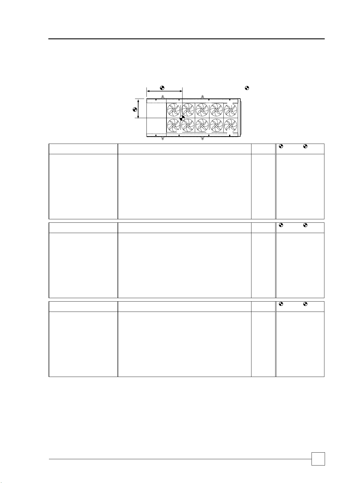
POINT LOADINGS, WEIGHTS & CENTRE OF GRAVITY (C OF G)
DOUBLE ROW FANS - /2
UCCU110 - UCCU450
P1
P3
P5
P2
P4
P6
P7
P8
1
2
= C of G
Model D P1
P2
P3
P4
P5
P6
P7
P8
Operating
Weight
C of G1
(mm)
C of G2
(mm)
UCCU110D-4/2
kg
380
380
(1)
(1)
(1)
(1)
280
280
1320
925
955
UCCU130D-4/2
kg
395
415
(1)
(1)
(1)
(1)
280
280
1370
940
930
UCCU160D-4/2
kg
470
470
(1)
(1)
(1)
(1)
235
235
1410
925
810
UCCU180D-6/2
kg
550
590
205
225
(2)
(2)
120
120
1810
955
1035
UCCU200D-6/2
kg
550
590
205
225
(2)
(2)
120
120
1810
955
1035
UCCU225D-6/2
kg
620
620
220
220
(2)
(2)
125
125
1930
925
1015
UCCU240D-8/2
kg
635
635
325
325
(2)
(2)
190
190
2300
1100
1450
UCCU250D-6/2
kg
620
620
220
220
(2)
(2)
125
125
1930
925
1015
UCCU270D-8/2
kg
680
680
330
330
(2)
(2)
195
195
2410
1100
1425
UCCU300D-8/2
kg
715
715
350
350
(2)
(2)
200
200
2530
1100
1415
UCCU330D-10/2
kg
690
690
340
340
190
190
190
190
2820
1100
1665
UCCU360D-10/2
kg
715
715
345
345
190
190
190
190
2880
1100
1640
UCCU400D-12/2
kg
740
740
380
380
255
255
245
245
3240
1100
2160
UCCU450D-12/2
kg
775
775
395
395
255
255
245
245
3340
1100
2120
Model DQ P1
P2
P3
P4
P5
P6
P7
P8
Operating
Weight
C of G1
(mm)
C of G2
(mm)
UCCU110DQ-4/2
kg
370
370
(1)
(1)
(1)
(1)
270
270
1280
925
950
UCCU130DQ-4/2
kg
385
405
(1)
(1)
(1)
(1)
265
265
1320
940
915
UCCU160DQ-6/2
kg
480
480
210
210
(2)
(2)
125
125
1630
925
1100
UCCU180DQ-6/2
kg
505
545
210
230
(2)
(2)
125
125
1740
955
1075
UCCU200DQ-6/2
kg
505
545
210
230
(2)
(2)
125
125
1740
955
1075
UCCU225DQ-8/2
kg
545
545
290
290
(2)
(2)
225
225
2120
925
1525
UCCU240DQ-8/2
kg
655
655
330
330
(2)
(2)
190
190
2350
1100
1435
UCCU250DQ-8/2
kg
545
545
290
290
(2)
(2)
225
225
2120
925
1525
UCCU270DQ-10/2
kg
650
650
325
325
195
195
180
180
2700
1100
1680
UCCU300DQ-10/2
kg
690
690
335
335
200
200
185
185
2820
1100
1660
UCCU330DQ-12/2
kg
715
715
375
375
245
245
230
230
3130
1100
2140
UCCU360DQ-12/2
kg
730
730
385
385
250
250
230
230
3190
1100
2130
UCCU400DQ-14/2
kg
760
760
415
415
300
300
290
290
3530
1100
2550
UCCU450DQ-14/2
kg
805
805
425
425
300
300
290
290
3640
1100
2490
Model DSQ
P1
P2
P3
P4
P5
P6
P7
P8
Operating
Weight
C of G1
(mm)
C of G2
(mm)
UCCU110DSQ-4/2
kg
380
380
(1)
(1)
(1)
(1)
270
270
1300
925
940
UCCU130DSQ-6/2
kg
380
400
210
210
(2)
(2)
200
200
1600
935
1320
UCCU160DSQ-6/2
kg
405
405
220
220
(2)
(2)
200
200
1650
925
1305
UCCU180DSQ-6/2
kg
425
465
225
245
(2)
(2)
200
200
1760
955
1275
UCCU200DSQ-8/2
kg
480
520
265
285
(2)
(2)
240
240
2030
950
1300
UCCU225DSQ-8/2
kg
535
535
290
290
(2)
(2)
245
245
2140
925
1575
UCCU240DSQ-10/2
kg
635
635
315
315
190
190
180
180
2640
1100
1690
UCCU250DSQ-8/2
kg
535
535
290
290
(2)
(2)
245
245
2140
925
1575
UCCU270DSQ-10/2
kg
695
695
340
340
245
245
225
225
3010
1100
2155
UCCU300DSQ-12/2
kg
730
730
355
355
250
250
225
225
3120
1100
2120
UCCU330DSQ-14/2
kg
760
760
405
405
280
280
270
270
3430
1100
2475
UCCU360DSQ-14/2
kg
780
780
410
410
280
280
270
270
3480
1100
2450
UCCU400DSQ-16/2
kg
805
805
460
460
430
430
320
320
4030
1100
2830
UCCU450DSQ-16/2
kg
835
835
475
475
435
435
320
320
4130
1100
2790
(1)
Have only 4 fixing and 4 point loadings.
(2)
Have only 6 fixing and 6 point loadings.
Page 14
ULTIMA COMPACT
Condensing Units
14
Condensers & Condensing Units
Installation & Maintenance : 6259675 IM V1.4.0 10/2013
Installation Data
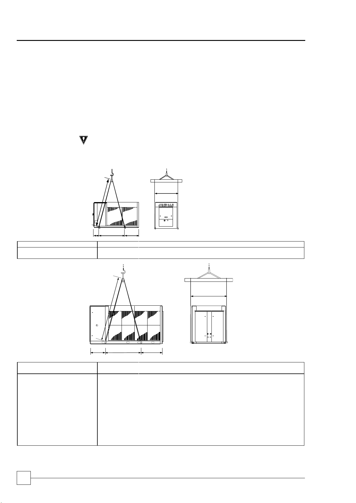
UNIT LIFTING
Employ lifting specialists.
Local codes and regulations relating to the lifting of this type of equipment should
be observed.
Use the lifting eye bolts/lifting lugs provided.
Attach lifting chains to the 4 lifting eye bolts/lifting lugs provided, each chain and
eye bolt must be capable of lifting the whole chiller.
Use the appropriate spreader bars/lifting slings with the holes/lugs provided.
Lift the unit slowly and evenly.
If the unit is dropped, it should immediately be checked for damage and reported
to Airedale Service.
CAUTION
Only use lifting points provided.
The unit should be lifted from the base and where possible, with all packing and
protection in position. If any other type of slinging is used, due care should be taken to
ensure that the slings do not crush the casework or coil.
LIFTING DIMENSIONS
A C B
E
D
UCCU30 - 80 (Except UCCU75)
A
B
(1)
C
(1)
D
(1)
E
1 FAN /1
mm
300
1050 (1450)
300 (300)
1900 (2200)
1270
2 FANS /1
mm
300
1450
750
2200
1270
E
A
B
C
D
UCCU75 - UCCU250
(Except UCCU80)
A B C D E
2 FANS /1
mm
290
1900
585
2500
1450
3 FANS /1
mm
290
2015
1320
2500
1450
4 FANS /1
mm
290
2870
1315
3000
1450
4 FANS /2
mm
180
1580
605
2500
2000
6 FANS /2
mm
595
1650
925
2500
2000
8 FANS /2
(Tandem Compressor)
mm
595
2050
1330
2500
2350
8 FANS /2
(Trio Compressor)
mm
465
2560
1625
3000
2350
10 FANS/2
mm
465
3135
1900
3500
2350
12 FANS/2
mm
465
3610
2275
3500
2350
14 FANS/2
mm
465
4385
2350
4000
2350
16 FANS/2
mm
465
5035
2600
5000
2350
Page 15
Condensing Units
ULTIMA COMPACT
Condensers & Condensing Units
15
Installation & Maintenance : 6259675 IM V1.4.0 10/2013
Chillers
ULTIMA COMPACT
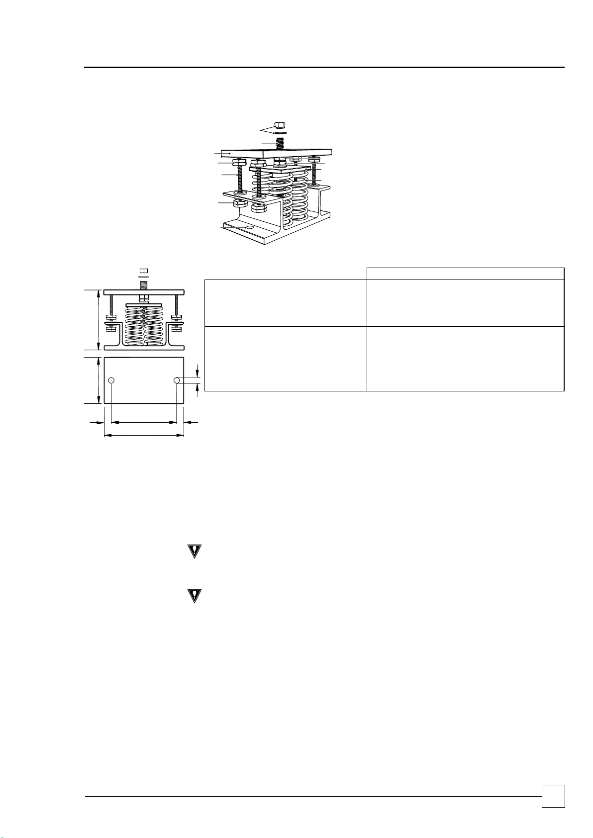
COMPONENTS:
1 Locating Screw
2 Retaining Nut & Washer
3 Levelling Screw
4 Levelling Lock Nut
5 Retaining Studs
6a Upper Retaining Nuts
6b Lower Retaining Nuts
7 Spring assembly
8 Pressure Plate
9 Top Plate
10 Bolting-down holes
2
1
6a
5
6b
10
9 8 7 3 4
DIMENSIONS:
B
A
C
D
E F E
A
(1)
B C D E
FØ
UCC30-70
2 SPRING
136
110
180
148
16
11
UCC75, 80, 100, 125 & 150
UCCU30-70
UCCU75, 80, 100, 125 & 150
UCFC75-150
UCC110, 130, 160-450
4 SPRING
180
130
225
186
20
16
UCCU110, 130, 160-450
UCFC160-450
UFC200-750
URAC75-450
USC200-750
UWC75-450
(1) Unloaded dimension
(2) Refer to relevant Loose Parts Instructions sheet for positioning of each mount.
INSTALLATION
1 Locate and secure mount using bolting down holes (10) in base plate.
2 Ensure mounts are located in line with the unit base.
3 If applicable, remove compressor enclosure covers to allow access to mount fixing holes in
the unit base.
4 Lock the upper retaining nuts (6a) to the underside of the top plate (9) before a load is
applied.
5 Remove retaining nut and washer (2), lower the unit onto the mounts and replace retaining
nut and washer.
6 Beginning with the mount with the largest deflection, adjust the height of each mount using
the levelling screw (3).
CAUTION
Mountings must be adjusted incrementally in turn. Do not fully adjust 1 mount at a time as
this may overload and damage springs.
7 When all mounts are level, lock each into place using the levelling lock nut (4).
8 Lock all retaining nuts (6a and 6b) to the extreme ends of the retaining studs (5).
CAUTION
Do not connect any services until all anti vibration mounts have been fully adjusted.
Installation Data
ANTI VIBRATION MOUNTING – OPTIONAL
Page 16
ULTIMA COMPACT
Condensing Units
16
Condensers & Condensing Units
Installation & Maintenance : 6259675 IM V1.4.0 10/2013
Installation Data
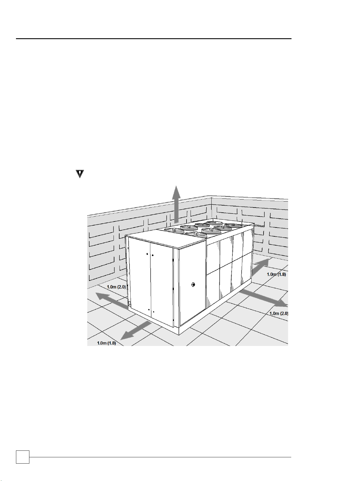
POSITIONING
The installation position should be selected with the following points in mind:
Position on a stable and even base, levelled to ensure that the compressor
operates correctly.
Levelling should be to +/- 5mm.
Where vibration transmission to the building structure is possible, fit spring anti-
vibration mounts and flexible water connections.
Observe airflow and maintenance clearances.
Pipework and electrical connections are readily accessible.
Where multiple units are installed, due care should be taken to avoid the
discharge air from each unit adversely affecting other units in the vicinity.
Within a side enclosed installation, the fan MUST be higher than the
enclosing structure.
Figures in brackets indicate airflow and maintenance clearances for side-enclosed
or multiple condensing unit applications.
Ensure there are no obstructions directly above the fans.
Allow free space above the fans to prevent air recirculation.
CAUTION
Prior to connecting services, ensure that the equipment is installed and
completely level.
Page 17
Installation & Maintenance : 6259675 IM V1.4.0 10/2013
Chillers
17
Chillers
ULTIMA COMPACT
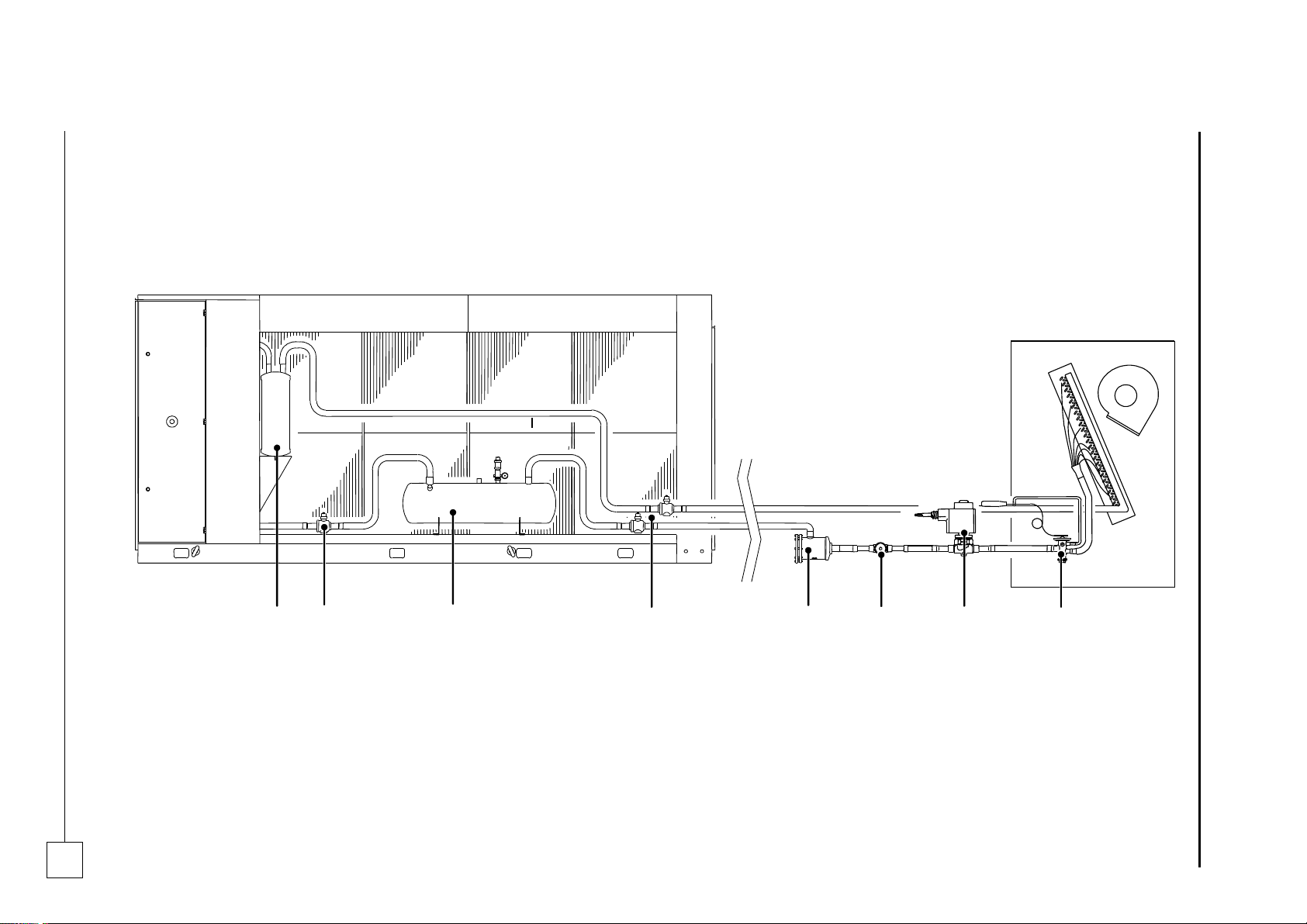
OUTDOOR UNIT - ULTIMA COMPACT CONDENSING UNIT
INDOOR UNIT - BY OTHERS
1 2 3 4 5 6 7
8
Installation Data
REFRIGERATION SYSTEM
Standard Recommended Installation
1 Suction accumulator (optional - factory fitted)
2 Receiver pump down ball valve (optional - factory fitted)
3 Liquid receiver & pressure relief assembly (optional - factory fitted)
4 Suction & liquid line ball valves (standard - factory fitted)
5 Filter drier (optional - supplied loose)
6 Sight glass (optional - supplied loose)
7 Solenoid valve (supplied by others)
8 Expansion valve (supplied by others)
Page 18
ULTIMA COMPACT
Condensing Units
18
Condensers & Condensing Units
Installation & Maintenance : 6259675 IM V1.4.0 10/2013
Installation Data
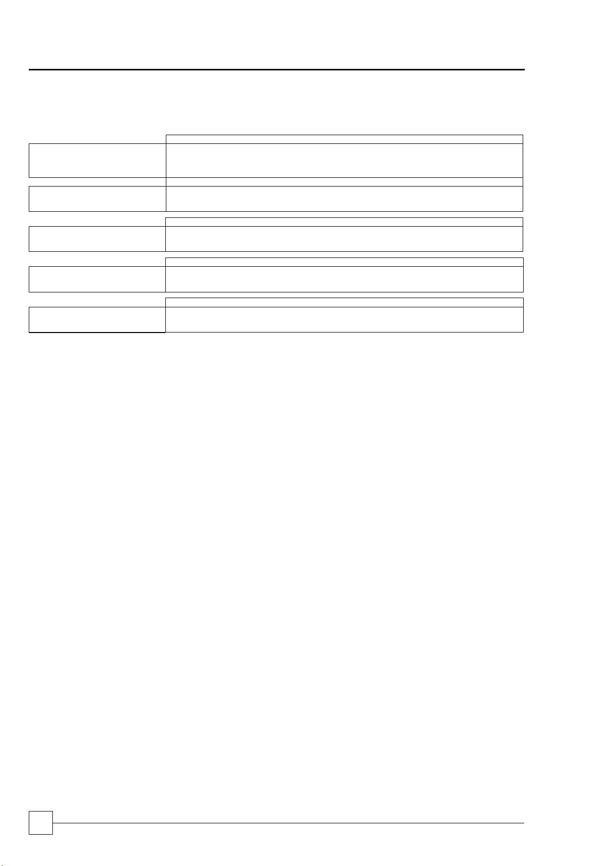
REFRIGERATION CONNECTIONS
UCCU30SQ-1/1
UCCU40SQ-1/1
UCCU50SQ-2/1
UCCU60SQ-2/1
UCCU70SQ-2/1
UCCU80SQ-2/1
Connections - Single
Circuit
(1)
Liquid Line
in
7/8
7/8
7/8
1 1/8
1 1/8
1 1/8
Suction Line
in
1 3/8
1 3/8
1 5/8
1 5/8
1 5/8
1 5/8
UCCU30DQ-1/1
UCCU40DQ-1/1
UCCU50DQ-2/1
UCCU60DQ-2/1
UCCU70DQ-2/1
UCCU80DQ-2/1
Connections - Dual Circuit
(1)
Liquid Line
in
3/4
3/4
3/4
7/8 / 3/4
7/8
7/8
Suction Line
in
1 1/8
1 1/8
1 1/8
1 3/8 / 1 1/8
1 3/8
1 3/8
UCCU75D-2/1
UCCU100D-2/1
UCCU110D-4/2
UCCU125D-3/1
UCCU130D-4/2
UCCU150D-3/1
Connections
(1)
Liquid Line
in
1 1/8
1 1/8
1 1/8
1 1/8
1 1/8
1 1/8
Suction Line
in
1 3/8
1 3/8
1 5/8
1 5/8
1 5/8
1 5/8
UCCU160D-4/2
UCCU180D-6/2
UCCU200D-6/2
UCCU225D-6/2
UCCU240D-8/2
UCCU250D-6/2
Connections
(1)
Liquid Line
in
1 1/8
1 1/8
1 3/8
1 3/8
1 5/8
1 3/8
Suction Line
in
2 1/8
2 1/8
2 1/8
2 1/8
2 5/8
2 1/8
UCCU270D-8/2
UCCU300D-8/2
UCCU330D -10/2
UCCU360D -10/2
UCCU400D -12/2
UCCU450D-12/2
Connections
(1)
Liquid Line
in
1 5/8
1 5/8
1 5/8 / 2 1/8
2 1/8
2 1/8
2 1/8
Suction Line
in
2 5/8
2 5/8
2 5/8
2 5/8
2 5/8 / 3 1/8
3 1/8
(1)
Suitable For Brazed Connections.
PIPE SIZING GUIDE
Pipework sizes and routes should be set in accordance with good refrigeration practice.
PIPEWORK
INSTALLATION
The suction line should be insulated.
Liquid lines should be insulated in areas of high temperature or when exposed to
direct sunlight.
Special consideration should be given to vertical pipe runs and heat pump installation.
Unit performance will reduce if there are vertical rises of above 5m. Please consult
Airedale Service for risers above 10m.
When insulating refrigerant lines, cut approximately 30 - 50cm longer than the distance
between the units to ensure the insulation goes right upto the unit. Leave connections
uncovered for leak testing.
Remove burrs to the ends of the copper tube, holding the tube downward to avoid
allowing dirt to contaminate the tube.
Where applicable insert flare nuts removed from the pipework terminations and make a
flare at the end of the copper tube to conform with the following:
Inside surface is glossy and smooth
Tapered sides are of uniform length
Refrigeration lubrication is applied to mating surfaces
The installation of a sight glass close to the indoor unit is recommended.
Where applicable braze incoming pipe to rotalock service valve.
Page 19
Condensing Units
ULTIMA COMPACT
Condensers & Condensing Units
19
Installation & Maintenance : 6259675 IM V1.4.0 10/2013
Chillers
ULTIMA COMPACT
Installation Data
PRESSURE TESTING
In accordance with PED 97/23/EC, a strength test should be carried out in order to
ensure that all interconnecting joints, pipework and components are sufficiently strong to
cater for maximum permissible operating pressures. Once installation is completed, the
high side of the system should be strength tested with dry nitrogen to a recommended
minimum pressure of 27 barg and the low side to 17 barg.
CAUTION
Pressure testing can be dangerous if not properly conducted, personnel
undertaking pressure testing MUST be technically competent and suitably
qualified.
When installation is complete, the system should be pressure tested.
Fill the system with dry nitrogen to a pressure of between 17 bar/250psig and 34bar/
500 psig.
Record the pressure over a minimum of 60 minutes to detect major leaks (a 24 hour
period should preferably be allowed).
If a reduction in pressure is detected, trace the leak and repair before conducting a further
pressure test and charging.
EVACUATION
Evacuation for systems operating with R407C refrigerant to be carried out as follows (for
alternative refrigerants please refer to Airedale).
Use a high vacuum pump and connect to the high and low pressure sides of the system
via a gauge manifold fitted with compound gauges. A high vacuum gauge should be fitted
to the system at the furthest point from the vacuum pump.
Triple evacuation should be used to ensure that all contaminants are removed.
Operate the vacuum pump until a pressure of 1.5 torr (200 Pa) absolute pressure is
reached, then stop the vacuum pump to break the vacuum using oxygen free Nitrogen
until the pressure rises above zero.
The above operation should be repeated a second time.
The system should then be evacuated a third time but this time to 0.5 torr
absolute pressure.
Break with the correct refrigerant, until pressures equalise between the charging bottle
and the system.
ELECTRICAL
General
As standard the equipment is designed for 400V, 3 phase, 3 wire 50Hz and a
separate permanent 230V, 1 phase, 50Hz supply, to all relevant IEE regulations,
British standards and IEC requirements.
A fused and isolated electrical supply of the appropriate phase, frequency and
voltage should be installed.
The control voltage to the interlocks is 24V. Always size the low voltage interlock
and protection cabling for a maximum voltage drop of 2V.
CAUTION
Wires should be capable of carrying the maximum load current under non-fault
conditions at the stipulated voltage.
Avoid large voltage drops on cable runs, particularly low voltage wiring.
Once the connecting pipework is complete the electrical supply can be connected
by routing the cable through the appropriate casing hole and connecting the
cables, refer to the Wiring Diagram supplied with each unit.
CAUTION
A separately fused, locally isolated, permanent single phase and neutral supply
MUST BE FITTED for the compressor sump heater and control circuits, FAILURE to
do so could INVALIDATE WARRANTY.
Page 20
ULTIMA COMPACT
Condensing Units
20
Condensers & Condensing Units
Installation & Maintenance : 6259675 IM V1.4.0 10/2013
Installation Data
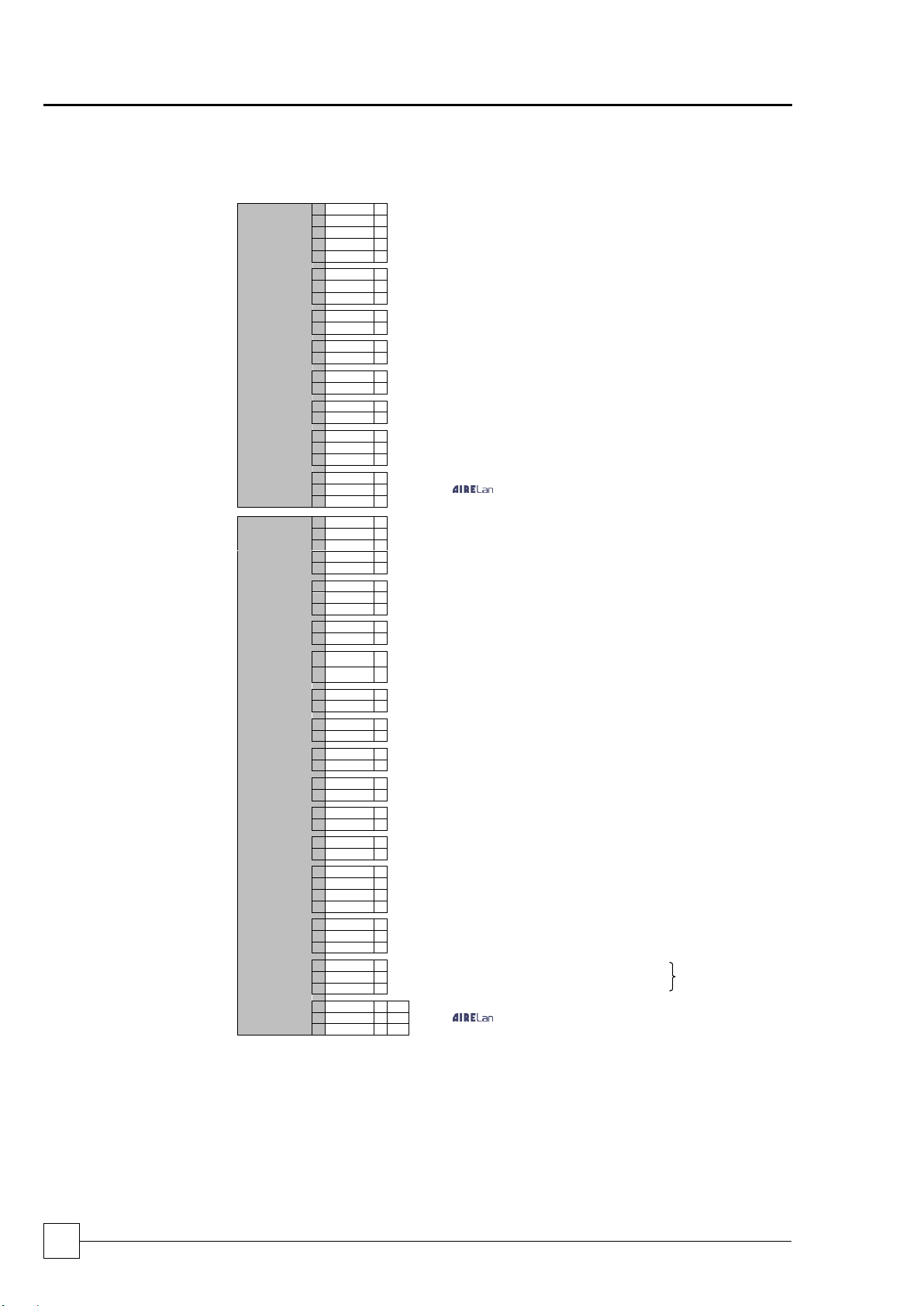
INTERCONNECTING WIRING
Single Circuit
(not including: leak detector,
and remote setpoint adjust)
UCCU30–
UCCU80
(Excluding
UCCU75)
L1
Mains incoming supply 400V/3PH/50Hz 50Hz
(N2 Only Required For UCCU30-80Q/DQ & UCCU50-60SSQ/DSQ)
L2
L3
N2
E
L4
Separate Permanent Supply 230V/1PH/50Hz
N1
E
502
Circuit 1 24VAC (Suction Pressure Control Option), Compressor.1 24VAC (Digital
I/P Control Option)
504
502
Remote On/Off 24VAC, Compressor.2 24VAC (Digital I/P Control Option)
505
500
0 v
Remote Capacity Control (0-10VDC Control Option)
806
0-10v 52
Circuit 1 Solenoid Valve
53
Volt Free Contact N/O
573
Circuit 1
Volt Free Common Alarm
574
Volt Free Alarm N/O
575
Volt Free Alarm N/C
RX-/TX-
RX+/TX+
/ Optional EEV Connections
GND
Double Circuit
UCCU30 –
UCCU450
L1
Mains incoming supply 400V/3PH/50Hz
(N2 Only Required For UCCU30-80Q/DQ & UCCU50-60SSQ/DSQ)
L2
L3
N2
E
L4
Separate Permanent Supply 230V/1PH/50Hz
N1
E
502
Circuit 1 24VAC (Suction Pressure Control Option) / Compressor.1 24VAC (Digital
I/P Control Option)
504
502
Unit Remote On/Off 24VAC, Circuit 2 24VAC (Suction Pressure Control Option),
Compessor.2 24VAC (Digital I/P Control Option)
505
502
Compressor.3 24VAC (Digital I/P Control Option)
506
502
Compressor.4 24VAC (Digital I/P Control Option)
507
502
Compressor.5 24VAC (Digital I/P Control Option UCCU240-450 Only Excluding
UCCU250)
508
502
Compressor.6 24VAC (Digital I/P Control Option UCCU240-450 Only Excluding
UCCU250)
509
502
Remote On/Off 24VAC, Compressor.2 24VAC (Digital I/P Control Option)
505
500
0 v
Remote Capacity Control (0-10VDC Control Option)
806
0-10v
52
Circuit 1 Solenoid Valve
53
Volt Free Contact N/O
54
Circuit 2 Solenoid Valve
55
Volt Free Contact N/O
573
Circuit 1
Volt Free Common Alarm
574
Volt Free Alarm N/O
575
Volt Free Alarm N/C
576
Circuit 2
Volt Free Common Alarm
Dual Circuit Only
577
Volt Free Alarm N/O
578
Volt Free Alarm N/C
RX-/TX-
/ Optional EEV Connections
RX+/TX+
GND
Page 21
Condensing Units
ULTIMA COMPACT
Condensers & Condensing Units
21
Installation & Maintenance : 6259675 IM V1.4.0 10/2013
Chillers
ULTIMA COMPACT
Installation Data
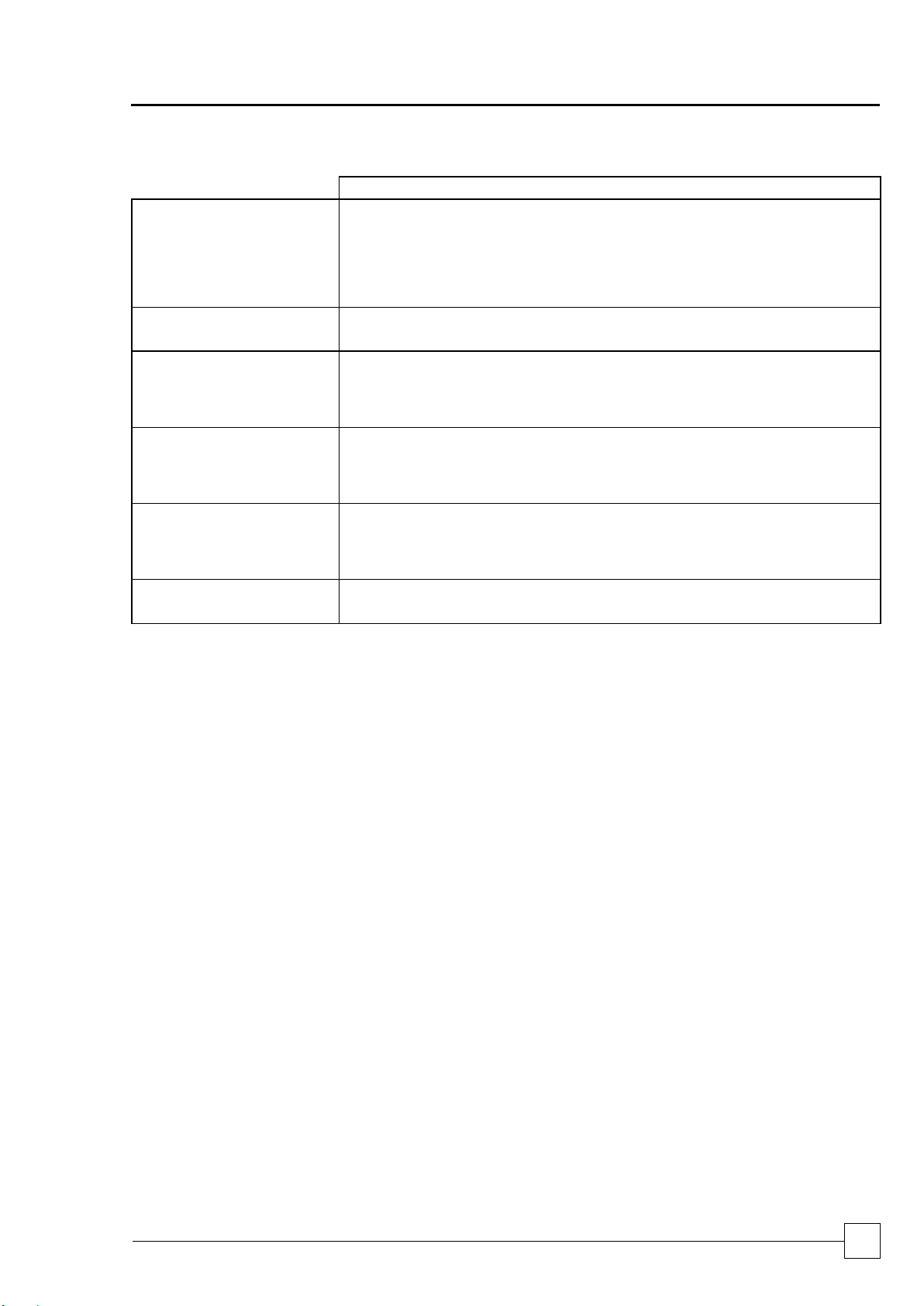
ELECTRICAL DATA
UCCU30SQ-1/1
UCCU30DQ-1/1
UCCU40SQ-1/1
UCCU40DQ-1/1
UCCU50SQ-2/1
UCCU50DQ-2/1
UCCU60SQ-2/1
UCCU60DQ-2/1
UCCU70SQ-2/1
UCCU70DQ-2/1
UCCU80SQ-2/1
UCCU80DQ-2/1
Unit Data
Nominal Run Amps
(1)
A
27
28
38
43
47
58
Maximum Start Amps
(2)
A
116
114
142
157
162
207
Permanent Supply
VAC
230 V 1 PH 50 Hz
Mains Supply
VAC
400 V 3 PH 50 Hz
Rec Permanent Fuse Size
A
16
16
16
16
16
16
Rec Mains Fuse Size
A
32
40
50
50
63
80
Max Permanent Incoming Cable Size
mm²
4 mm² terminals
Max Mains Incoming Cable Size
mm²
35 (Direct to Isolator)
Control Circuit
VAC
24V/230VAC
Condenser Fan - Per Fan
Full Load Amps
A
3.00
3.00
3.00
3.00
3.00
3.00
Locked Rotor Amps
A
7.00
7.00
7.00
7.00
7.00
7.50
Motor Rating
Kw
1.75
1.75
1.75
1.75
1.75
1.75
Compressor - Per Compressor
Quantity
2 2 2 2 2
2
Motor Rating
kW
4.7
6.2
8.1
9.5 / 8.1
9.5
11.7
Nominal Run Amps
(1)
A
12.0
12.7
16.1
20.7 / 16.1
20.7
26.0
Crankcase Heater Rating
W
70.0
65.0
65.0
65.0 / 75.0
65.0
70.0
Start Amps
(2)
101.0
98.0
120.0
135.0 / 120.0
135.0
175.0
Type Of Start
Direct on line
SUPER QUIET SQ
UCCU30SSQ-1/1
UCCU30DSQ-1/1
UCCU40SSQ-1/1
UCCU40DSQ-1/1
UCCU50SSQ-2/1
UCCU50DSQ-2/1
UCCU60SSQ-2/1
UCCU60DSQ-2/1
UCCU70SSQ-2/1
UCCU70DSQ-2/1
UCCU80SSQ-2/1
UCCU80DSQ-2/1
All data as above except:
Condenser Fan - Per Fan
Full Load Amps
A
1.15
1.15
3.50
3.50
1.15
1.15
Locked Rotor Amps
A
2.10
2.10
7.50
7.50
2.10
2.10
Motor Rating
kW
0.70
0.70
0.78
0.78
0.70
0.70
OPTIONAL EXTRAS
Power Factor Correction
Nominal Run Amps
(1)
A
N/A
N/A
N/A
N/A
N/A
N/A
Maximum Start Amps
(2)
A
N/A
N/A
N/A
N/A
N/A
N/A
Recommended Mains Fuse
A
N/A
N/A
N/A
N/A
N/A
N/A
Compressor Nominal Run Amps
- Per Compressor
A
N/A
N/A
N/A
N/A
N/A
N/A
Electronic Soft-start
Nominal Run Amps
(1)
A
27
28
38
43
47
58
Maximum Start Amps
(2)
A
76
77
94
103
108
137
Recommended Mains Fuse
A
32
40
50
50
63
80
(1)
Based at 7.2°C Evaporating and 54.4°C Condensing temperatures.
(2)
Starting amps refers to the direct on line connections.
Page 22
ULTIMA COMPACT
Condensing Units
22
Condensers & Condensing Units
Installation & Maintenance : 6259675 IM V1.4.0 10/2013
Installation Data
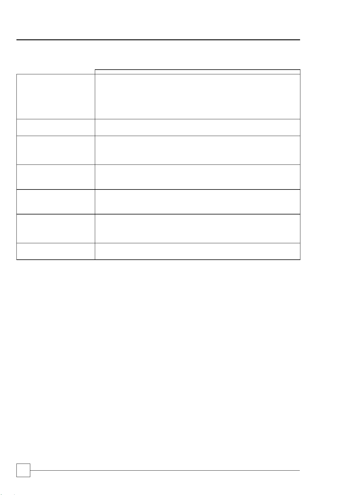
ELECTRICAL DATA
UCCU75D-2/1
UCCU100D-2/1
UCCU110D-4/2
UCCU125D-3/1
UCCU130D-4/2
UCCU150D-3/1
Unit Data
Nominal Run Amps
(1)
A
54
68
75
89
95
109
Maximum Start Amps
(2)
A
140
172
179
238
244
258
Permanent Supply
VAC
230 V 1 PH 50 Hz
Mains Supply
VAC
400 V 3 PH 50 Hz
Rec Permanent Fuse Size
A
16
16
16
16
16
16
Rec Mains Fuse Size
A
63
80
100
125
125
125
Max Permanent Incoming Cable Size
mm²
4 mm² terminals
Max Mains Incoming Cable Size
mm²
70 (Direct to
MCCB)
70 (Direct to
MCCB)
Direct to Bus Bar
70 (Direct to
MCCB)
Direct to Bus Bar
70 (Direct to
MCCB)
Control Circuit
VAC
24V/230V AC
Condenser Fan - Per Fan
Full Load Amps
A
1.75
1.75
3.00
1.75
3.00
1.75
Locked Rotor Amps
A
6.20
6.20
7.00
6.20
7.00
6.20
Motor Rating
kW
0.98
0.98
1.75
0.98
1.75
0.98
Compressor - Per Compressor
Quantity
4 4 4
2 + 2
2 + 2
4
Motor Rating
kW
6.2
8.1
8.1
8.1 / 11.7
8.1 / 11.7
11.7
Nominal Run Amps
(1)
A
12.7
16.1
16.1
16.1/ 26.0
16.1 / 26.0
26.0
Crankcase Heater Rating
W
65.0
65.0
65.0
65.0 / 75.0
65.0 / 75.0
75.0
Start Amps
(2)
98.0
120.0
120.0
120.0 / 175.0
120.0 / 175.0
175.0
Type Of Start
Direct on line
QUIET DQ
UCCU75DQ-2/1
UCCU100DQ-2/1
UCCU110DQ-4/2
UCCU125DQ-3/1
UCCU130DQ-4/2
UCCU150DQ-4/1
All data as above except:
Condenser Fan - Per Fan
Full Load Amps
A
1.15
1.15
1.25
1.15
1.25
1.15
Locked Rotor Amps
A
2.10
2.10
4.50
2.10
4.50
2.10
Motor Rating
kW
0.68
0.68
0.69
0.68
0.69
0.68
SUPER QUIET DSQ
UCCU75DSQ-3/1
UCCU100DSQ-3/1
UCCU110DSQ-4/2
UCCU125DSQ-4/1
UCCU130DSQ-6/2
UCCU150DSQ-4/1
All data as above except:
Condenser Fan - Per Fan
Full Load Amps
A
0.83
0.83
0.78
0.83
0.78
0.83
Locked Rotor Amps
A
1.50
1.50
1.50
1.50
1.50
1.50
Motor Rating
kW
0.32
0.32
0.48
0.32
0.48
0.32
OPTIONAL EXTRAS
Power Factor Correction
Nominal Run Amps
(1)
A
49
61
68
80
86
97
Maximum Start Amps
(2)
A
140
172
179
238
244
258
Recommended Mains Fuse
A
63
80
100
125
125
125
Compressor Nominal Run Amps
- Per Compressor
A
4 x 11
4 x 13
4 x 13
2 x 20 / 2 x 13
2 x 20 / 2 x 13
4 x 20
Electronic Soft-start
Nominal Run Amps
(1)
A
54
68
75
89
95
109
Maximum Start Amps
(2)
A
100
124
131
168
174
188
Recommended Mains Fuse
A
63
80
100
125
125
125
(1)
Based at 7.2°C Evaporating and 54.4°C Condensing temperatures.
(2)
Starting amps refers to the direct on line connections.
Page 23
Condensing Units
ULTIMA COMPACT
Condensers & Condensing Units
23
Installation & Maintenance : 6259675 IM V1.4.0 10/2013
Chillers
ULTIMA COMPACT
Installation Data
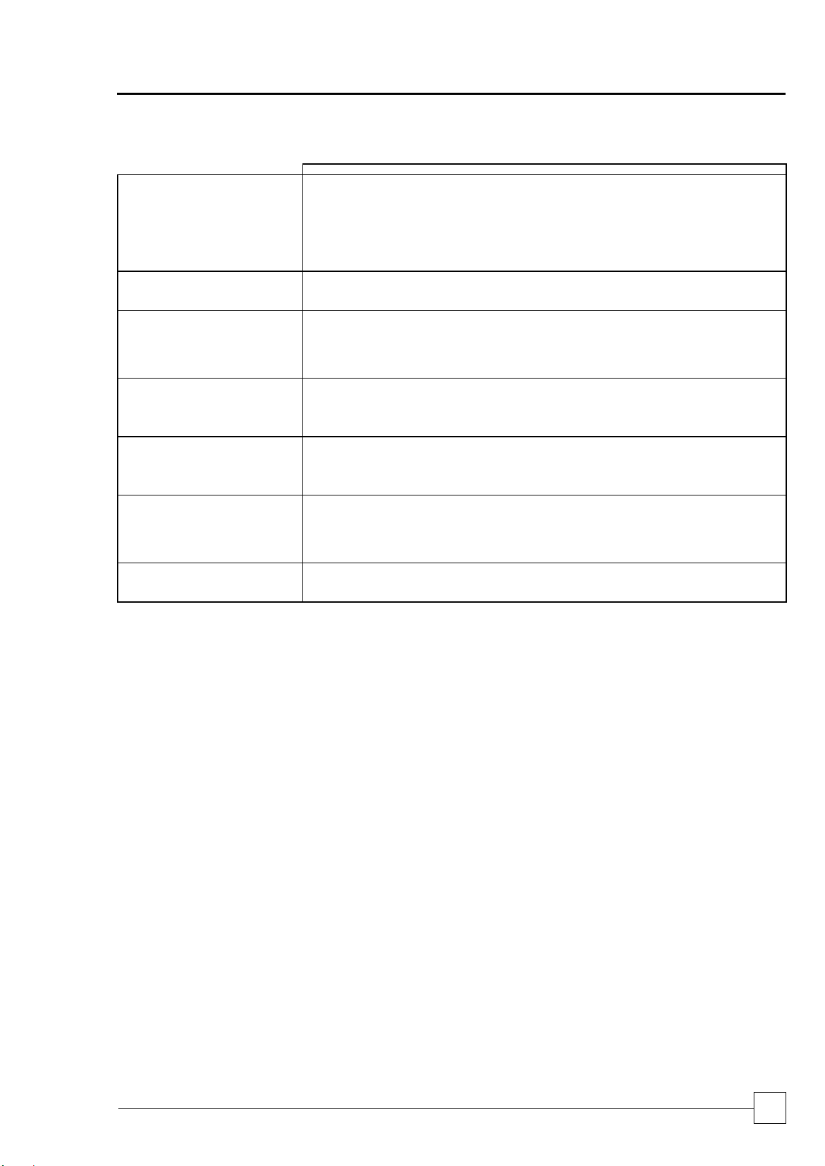
ELECTRICAL DATA
UCCU160D-4/2
UCCU180D-6/2
UCCU200D-6/2
UCCU225D-6/2
UCCU240D-8/2
UCCU250D-6/2
Unit Data
Nominal Run Amps
(1)
A
115
132
146
158
170
172
Maximum Start Amps
(2)
A
264
315
377
389
319
403
Permanent Supply
VAC
230 V 1 PH 50 Hz
Mains Supply
VAC
400 V 3 PH 50 Hz
Rec Permanent Fuse Size
A
16
16
16
16
16
16
Rec Mains Fuse Size
A
125
160
160
200
200
200
Max Permanent Incoming Cable Size
mm²
4 mm² terminals
Max Mains Incoming Cable Size
mm²
Direct to Bus Bar
Control Circuit
VAC
24V/230V AC
Condenser Fan - Per Fan
Full Load Amps
A
3.00
3.00
3.00
3.00
3.00
3.00
Locked Rotor Amps
A
7.00
7.00
7.00
7.00
6.20
7.00
Motor Rating
kW
1.75
1.75
1.75
1.75
1.75
1.75
Compressor - Per Compressor
Quantity
4
2 + 2
2 + 2
2 + 2 6 4
Motor Rating
kW
11.7
15.0 / 11.7
18.2 / 11.7
18.2 / 15.0
11.7
18.2
Nominal Run Amps
(1)
A
26.0
32.0 / 26.0
39.0 / 26.0
39.0 / 32.0
26.0
39.0
Crankcase Heater Rating
W
75.0
130.0 / 75.0
130.0 / 75.0
130.0 / 130.0
75.0
130.0
Start Amps
(2)
175.0
215.0 / 175.0
270.0 / 175.0
270.0 / 215.0
175.0
270.0
Type Of Start
Direct on line
QUIET DQ
UCCU160DQ-6/2
UCCU180DQ-6/2
UCCU200DQ-6/2
UCCU225DQ-8/2
UCCU240DQ-8/2
UCCU250DQ-8/2
All data as above except:
Condenser Fan - Per Fan
Full Load Amps
A
1.25
1.25
1.25
1.25
1.15
1.25
Locked Rotor Amps
A
4.50
4.50
4.50
4.50
2.10
4.50
Motor Rating
kW
0.69
0.69
0.69
0.69
0.70
0.69
SUPER QUIET DSQ
UCCU160DSQ- 6/2
UCCU180DSQ- 6/2
UCCU200DSQ- 8/2
UCCU225DSQ- 8/2
UCCU240DSQ-10/2
UCCU250DSQ- 8/2
All data as above except:
Condenser Fan - Per Fan
Full Load Amps
A
0.78
0.78
0.78
0.78
0.83
0.78
Locked Rotor Amps
A
1.50
1.50
1.50
1.50
1.50
1.50
Motor Rating
kW
0.48
0.48
0.48
0.48
0.32
0.48
OPTIONAL EXTRAS
Power Factor Correction
Nominal Run Amps
(1)
A
103
118
132
142
152
156
Maximum Start Amps
(2)
A
264
315
377
389
319
403
Recommended Mains Fuse
A
125
125
160
160
160
200
Compressor Nominal Run Amps
- Per Compressor
A
4 x 20
2 x 24 / 2 x 20
2 x 30 / 2 x 20
2 x 30 / 2 x 24
6 x 20
4 x 30
Electronic Soft-start
Nominal Run Amps
(1)
A
115
132
146
158
170
172
Maximum Start Amps
(2)
A
194
229
269
281
249
295
Recommended Mains Fuse
A
125
160
160
200
200
200
(1)
Based at 7.2°C Evaporating and 54.4°C Condensing temperatures.
(2)
Starting amps refers to the direct on line connections.
Page 24
ULTIMA COMPACT
Condensing Units
24
Condensers & Condensing Units
Installation & Maintenance : 6259675 IM V1.4.0 10/2013
Installation Data
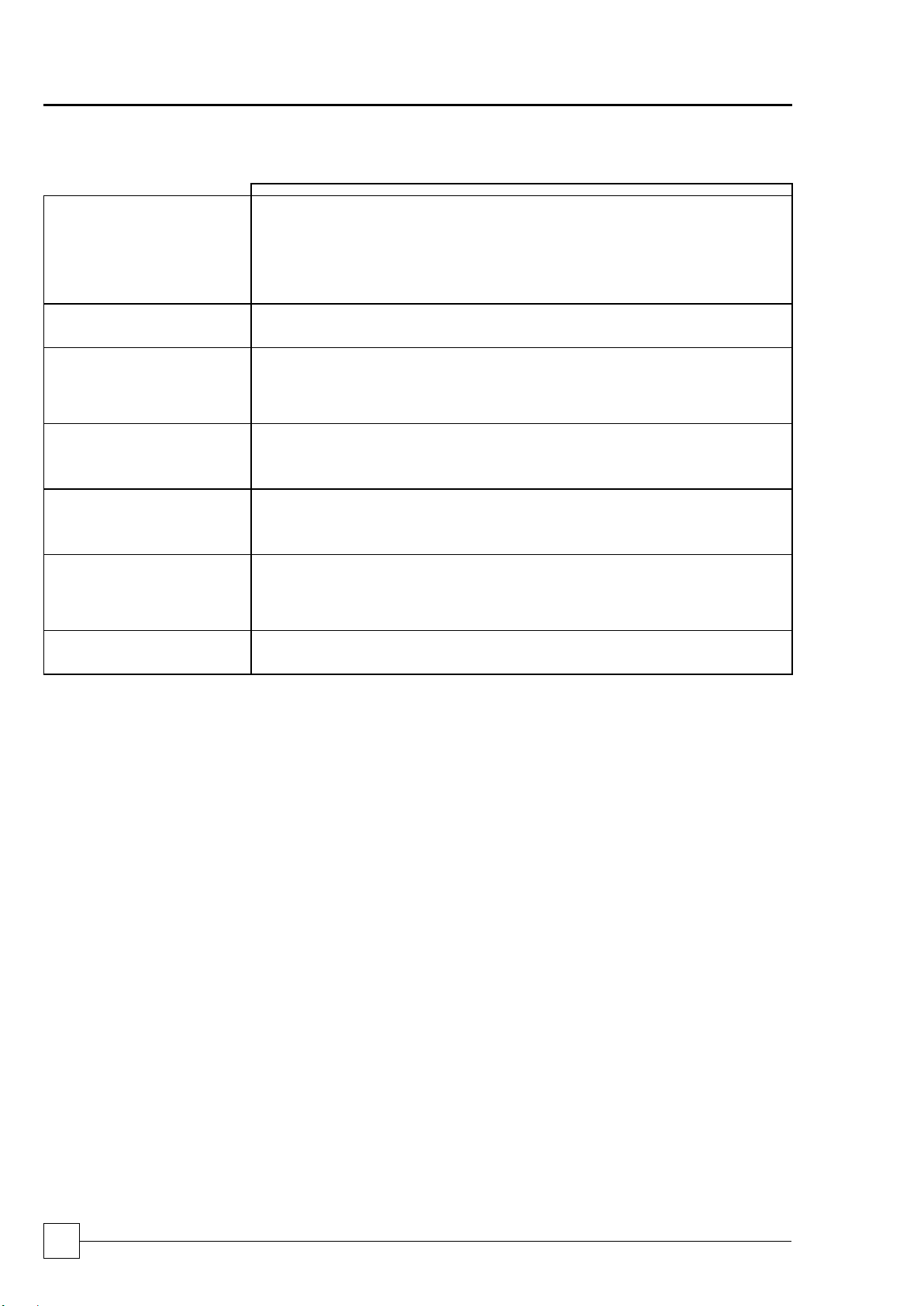
ELECTRICAL DATA
UCCU270D-8/2
UCCU300D-8/2
UCCU330D-10/2
UCCU360D-10/2
UCCU400D-12/2
UCCU450D-12/2
Unit Data
Nominal Run Amps
(1)
A
188
206
231
252
279
303
Maximum Start Amps
(2)
A
337
389
462
483
552
576
Permanent Supply
VAC
230 V 1 PH 50 Hz
Mains Supply
VAC
400 V 3 PH 50 Hz
Rec Permanent Fuse Size
A
16
16
16
16
16
16
Rec Mains Fuse Size
A
200
250
250
315
315
355
Max Permanent Incoming Cable Size
mm²
4 mm² terminals
Max Mains Incoming Cable Size
mm²
Direct to Bus Bar
Control Circuit
VAC
24V/230V AC
Condenser Fan - Per Fan
Full Load Amps
A
1.75
1.75
1.75
1.75
1.75
1.75
Locked Rotor Amps
A
6.20
6.20
6.20
6.20
6.20
6.20
Motor Rating
kW
0.98
0.98
0.98
0.98
0.98
0.98
Compressor - Per Compressor
Quantity
3 + 3 6 3 + 3 6 3 + 3
6
Motor Rating
kW
15.0 / 11.7
15.0
18.2 / 15.0
18.2
22.8 / 18.2
22.8
Nominal Run Amps
(1) A 32.0 / 26.0
32.0
39.0 / 32.0
39.0
47.0 / 39.0
47.0
Crankcase Heater Rating
W 130.0 / 75.0
130.0
130.0 / 130.0
130.0
130.0 / 130.0
130.0
Start Amps
(2) 215.0 / 175.0
215.0
270.0 / 215.0
270.0
320.0 / 270.0
320.0
Type Of Start
Direct on line
QUIET DQ
UCCU270DQ-10/2
UCCU300DQ-10/2
UCCU330DQ-12/2
UCCU360DQ-12/2
UCCU400DQ-14/2
UCCU450DQ-14/2
All data as above except:
Condenser Fan - Per Fan
Full Load Amps
A
1.15
1.15
1.15
1.15
1.15
1.15
Locked Rotor Amps
A
2.10
2.10
2.10
2.10
2.10
2.10
Motor Rating
kW
0.70
0.70
0.70
0.70
0.70
0.70
SUPER QUIET DSQ
UCCU270DSQ-12/2
UCCU300DSQ- 12/2
UCCU330DSQ- 14/2
UCCU360DSQ- 14/2
UCCU400DSQ- 16/2
UCCU450DSQ- 16/2
All data as above except:
Condenser Fan - Per Fan
Full Load Amps
A
0.83
0.83
0.83
0.83
0.83
0.83
Locked Rotor Amps
A
1.50
1.50
1.50
1.50
1.50
1.50
Motor Rating
kW
0.32
0.32
0.32
0.32
0.32
0.32
OPTIONAL EXTRAS
Power Factor Correction
Nominal Run Amps
(1)
A
167
182
207
228
246
261
Maximum Start Amps
(2)
A
337
389
362
483
552
576
Recommended Mains Fuse
A
200
200
250
250
250
315
Compressor Nominal Run Amps
- Per Compressor
A
3 x 24 / 3 x 20
6 x 24
3 x 30 / 3 x 24
6 x 30
3 x 36 / 3 x 30
6 x 36
Electronic Soft-start
Nominal Run Amps
(1)
A
188
206
231
252
279
303
Maximum Start Amps
(2)
A
267
303
354
375
424
448
Recommended Mains Fuse
A
200
250
250
315
315
355
(1)
Based at 7.2°C Evaporating and 54.4°C Condensing temperatures.
(2)
Starting amps refers to the direct on line connections.
Page 25
Condensing Units
ULTIMA COMPACT
Condensers & Condensing Units
25
Installation & Maintenance : 6259675 IM V1.4.0 10/2013
Chillers
ULTIMA COMPACT
-
Controls
GENERAL
DESCRIPTION
The microprocessor controller offers powerful analogue and digital control to meet a wide
range of monitoring and control features including a real time clock and Industry standard
communication port and network connections.
The controller’s inbuilt display is used for viewing the unit operating status and making
adjustments to control parameters by allowing the operator access to a series of
display pages.
Also featured are a visual alarm and the facility to adjust and display control settings by
local operator for information and control.
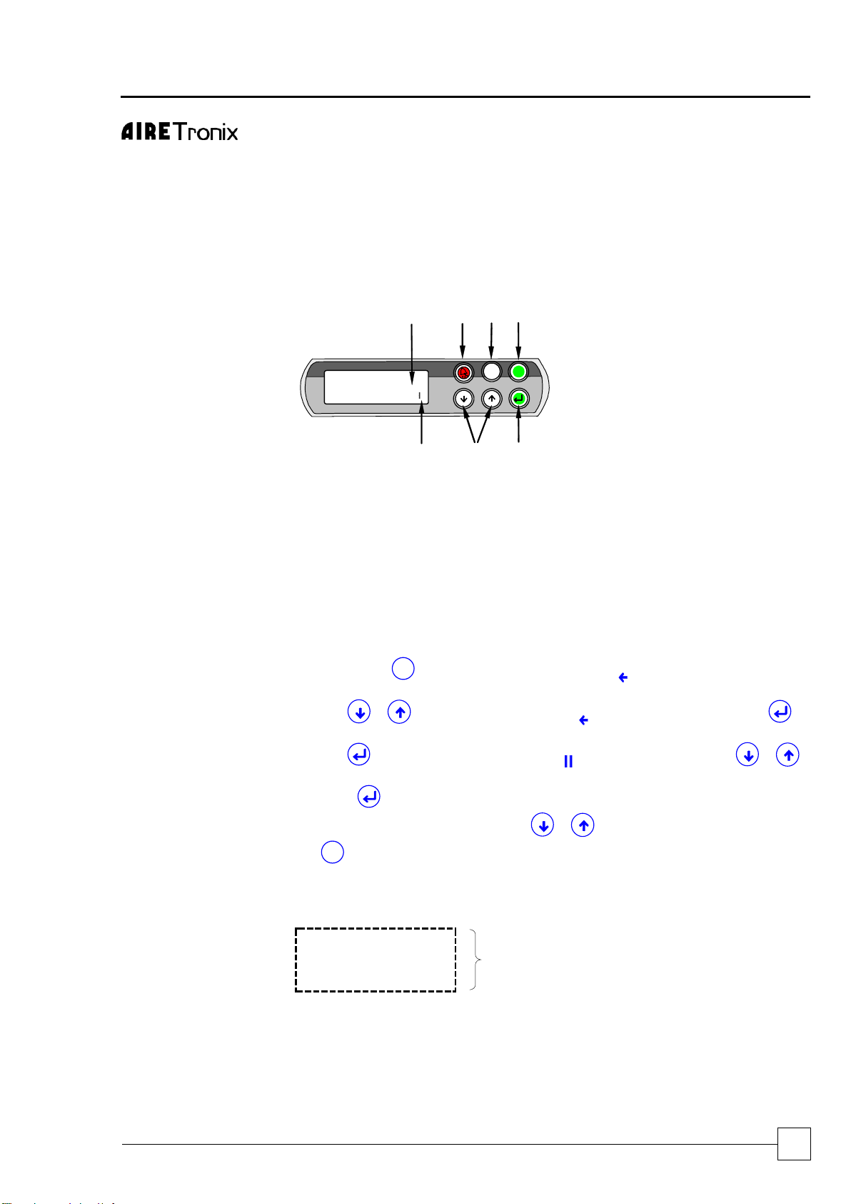
DISPLAY/KEYPAD
5
3
6
2
1
4
08:44 13/05/02 Mst
Remote 0-10V Input
Signal Voltage 05.6V
Unit ON
7
Esc
Prg
1 UP/DOWN KEYS
To change Adjustable Fields & Scrolls
up & down available Menus
2 ENTER
Selects Menus & Moves Cursor to
Adjustable Fields Green LED
3 ESC
Green LED lit when Operating Page
displayed, Returns to Operating Page
Screen when pressed
4 PROGRAM
Opens the Available Menus
5 ALARM
Red LED Indicates Alarm Present
6 4 ROW LCD DISPLAY
7 CURSOR (FLASHING): Top Left
Position = “HOME” Indicates adjustable
Fields
Navigation
The display is used for Viewing Unit Operating Status and Adjusting Customer
Control Settings by allowing the operator access to a series of Menus & sub-menus.
Viewing information is unrestricted, however set up and adjustment requires password
entry, refer to Password Protection.
Initially, use the
Prg
key to access Menus, the symbol will appear top right and the
first menu will appear in CAPITALS, these indicators shows which menu is selected.
Use the keys to move the indicator to the desired menu and press to
open the menu.
Use the key to move the flashing cursor to adjustable fields and the
keys to change the values.
Press the key to move the cursor to the next field or Home.
When the cursor is Home either use the keys to scroll to next sub-menu or
the
Esc
to exit and return to the Standard Operating page.
Standard Operating
Page
The Operating Page will appear and remain present following start up of the controller
as illustrated:
13:43 25/11/02 M1
Space Temp. 12.0°C
Supply Temp. 07.0°C
Unit ON:
Indicates current Time, Date, Space and Supply air
Temperatures and Unit On/Off
Page 26
ULTIMA COMPACT
Condensing Units
26
Condensers & Condensing Units
Installation & Maintenance : 6259675 IM V1.4.0 10/2013
-
Controls
OPERATION (CONT..)
Standard Operating
Page cont.
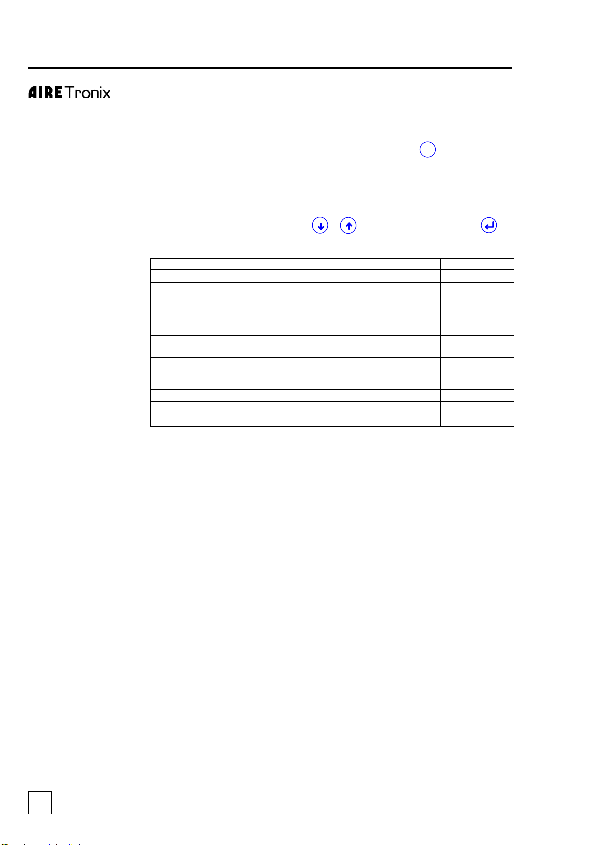
The following Menus can be accessed from the Operating Page, it is recommended that
the display is always returned to the Operating Page by using the
Esc
key
Password Protection
To guard against unauthorised adjustments, a password is required to gain access to
certain menus as defined below.
FACTORY SET PASSWORD PIN NUMBER: 4648 (or Customer chosen number).
When a password is requested use the keys to enter the number and to
access the page.
Menus
(Listed in Sequence)
Menu
Description
Password
Switch On/Off
Enable or Disable the unit
Open Access
Service
Allows selection of setpoint limits, enables unit on/off
from display, remote on/off and remote pump on/off.
Default 4648
Setpoint
Allows setpoint adjustment, includes supply
temperature setpoint and unit temperature
differential.
Default 4648
Status
Displays current status on digital and analogue inputs
and outputs.
Open Access
Maintenance
Displays hours run for compressors and pumps (if
fitted). Also includes Electronic Expansion Valves (if
fitted).
Default 4648
Clock
Allows adjustment of real time clock, time zones
Default 4648
Alarm Log
Display last 100 alarms in chronological order.
Open Access
Manufacturer
Factory use only.
Airedale Only
VIEWING UNIT OPERATING STATUS
Status Menu
Allows access to view operating status of Digital and Analogue Inputs and Outputs.
Using the Navigation instructions and the wiring diagram provided, the relevant Sub-
Menus can be accessed.
SETTING UP
Real Time Clock
(Optional to UCC30-80 Single
Circuit Only)
The units leave the factory set, however follow the Navigation instructions if necessary.
Time Zones
The programme provides 3 On/Off periods per day, 7 days per week. The unit is factory
set for continuous operation.
Technical Support
For further details, please contact Airedale.
Page 27
Condensing Units
ULTIMA COMPACT
Condensers & Condensing Units
27
Installation & Maintenance : 6259675 IM V1.4.0 10/2013
Chillers
ULTIMA COMPACT
-
Controls
ALARMS
The controller logs and allows viewing of the last 100 conditions recorded in descending
chronological order.
13/05/02 11:32
Event number 001
Alarm Active
37-Diff Pressr Evap
Alarm Handling
1 A Red LED behind the Alarm key will light in the event of an alarm. To view
the alarms, simply press the key and the keys to scroll through.
2 Auto reset alarms will clear following this first depression of the Alarm key. If
however the Red LED behind the Alarm key remains illuminated, the unit
requires some form of manual reset.
3 For manual reset alarms, isolate the affected circuits before further investigation.
4 To reset or delete the alarms displayed in the alarm screen, simply press
again.
COMMON ALARMS
Outlined below is a selection of Common Alarms, a full list is available, please
contact Airedale.
Phase Rotation
(Optional)
A normally closed contact. When Phase Rotation is incorrect all controller outputs are
de-activated.
Emergency Stop
A normally open contact. On closing, all controller outputs are de-activated.
INDIVIDUAL CIRCUIT
ALARMS
Outlined below is a selection of Individual Circuit Alarms, a full list is available, please
contact Airedale.
Low Suction Pressure
When the suction pressure sensor value falls below the value set by the low suction level
for a period exceeding 1 minute (or 3 minutes on compressor start-up), a visual alarm will
be generated at the in-built display and the relevant compressor will be de-activated. On
units with tandem compressors, both compressors from the same circuit will be
switched off.
High Liquid Pressure
When the liquid pressure reaches 25 BarG, the relevant circuit will be switched off and an
alarm activated, this can only be rectified by manual reset via the microprocessor.
Compressor Status
A normally closed contact when the compressor is operating. If this contact remains open
for a period of 3 seconds during operation of the compressor, a visual alarm is generated
and the relevant compressor will be de-activated. This alarm comprises of compressor
motor protection module, discharge gas thermostat and safety high pressure switch.
Page 28
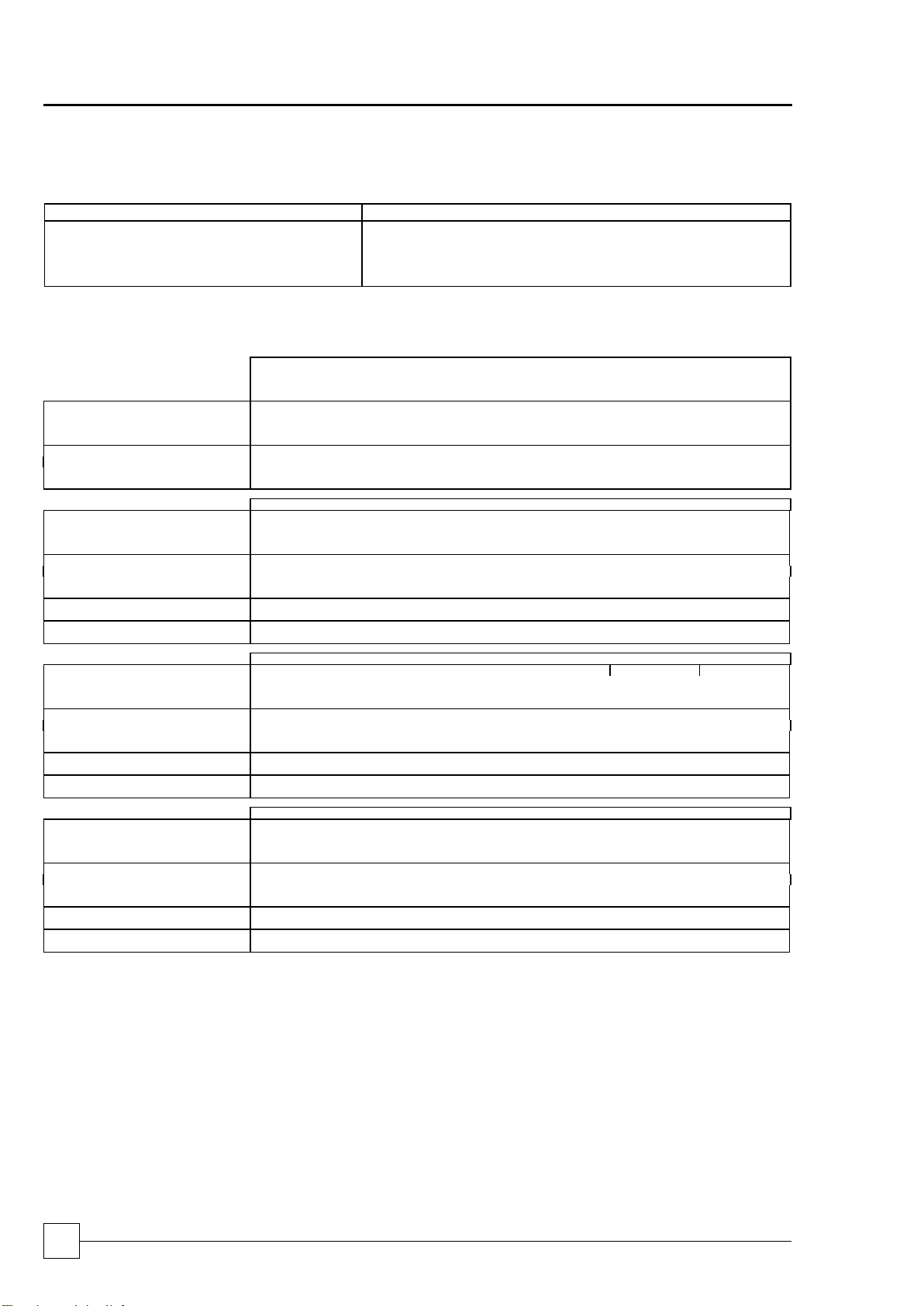
ULTIMA COMPACT
Condensing Units
28
Condensers & Condensing Units
Installation & Maintenance : 6259675 IM V1.4.0 10/2013
Commissioning Data
OPERATING LIMITS
Cooling
Standard Unit with Electronic Fan Speed Control (-20°C)
Minimum Ambient Air DB °C
-20°C
Maximum Ambient Air DB °C
Refer to Technical Manual - Performance Data - Capacity Data
Minimum Evaporating Temperature °C
-5°C
Maximum Evaporating Temperature °C
+10°C
1
For conditions outside those quoted, please refer to Airedale.
MECHANICAL DATA
Oil & Refrigerant Charges
UCCU30SQ-1/1
UCCU30DQ-1/1
UCCU40SQ-1/1
UCCU40DQ-1/1
UCCU50SQ-2/1
UCCU50DQ-2/1
UCCU60SQ-2/1
UCCU60DQ-2/1
UCCU70SQ-2/1
UCCU70DQ-2/1
UCCU80SQ-2/1
UCCU80DQ-2/1
UCCU30SSQ-1/1
UCCU30DSQ-1/1
UCCU40SSQ-1/1
UCCU40DSQ-1/1
UCCU50SSQ-2/1
UCCU50DSQ-2/1
UCCU60SSQ-2/1
UCCU60DSQ-2/1
UCCU70SSQ-2/1
UCCU70DSQ-2/1
UCCU80SSQ-2/1
UCCU80DSQ-2/1
Compressor
Single Circuit - Tandem Scroll / Double Circuit – 2 x Single Scroll
Quantity
2 2 2 2 2
2
Oil Charge Volume (Total)
l
1.5 + 1.5
1.6 + 1.6
1.9 + 1.9
3.0 + 1.9
3.0 + 3.0
3.6 + 3.6
Oil Type
Polyol Ester
Refrigeration
Single Circuit / Double Circuit
Holding Charge
Helium to 6.9 barg
Refrigerant Type
R407C
Charge (Total)
(1)
kg
5 + 5
6 + 6
6 + 6
8 + 8
8 + 8
10 + 10
UCCU75D-2/1
UCCU100D-2/1
UCCU110D-4/2
UCCU125D-3/1
UCCU130D-4/2
UCCU150D-3/1
Compressor
Tandem Scroll - Hermetic
Quantity
4 4 4 4 4
4
Oil Charge Volume (Total)
l
4 x 3.25
4 x 3.80
4 x 3.80
2 x 6.20+2 x 3.80
2 x 6.20+2 x 3.80
4 x 6.20
Oil Type
Polyol Ester
Refrigeration
Dual Circuit
Holding Charge
Helium to 6.9 barg
Refrigerant Type
R407C
Charge (Total)
(1)
kg
20 + 20
22 + 22
22 + 22
25 + 25
22 + 22
30 + 30
QUIET DQ
UCCU75DQ-2/1
UCCU100DQ-2/1
UCCU110DQ-4/2
UCCU125DQ-3/1
UCCU130DQ-4/2
UCCU150DQ-4/1
Refrigerant Charge (Total)
(1)
kg
20 + 20
25 + 25
22 + 22
30 + 30
22 + 22
40 + 40
SUPER QUIET DSQ
UCCU75DSQ-3/1
UCCU100DSQ-3/1
UCCU110DSQ-4/2
UCCU125DSQ-4/1
UCCU130DSQ-6/2
UCCU150DSQ-4/1
Refrigerant Charge (Total)
(1)
kg
20 + 20
23 + 23
22 + 22
40 + 40
30 + 30
40 + 40
UCCU160D-4/2
UCCU180D-6/2
UCCU200D-6/2
UCCU225D-6/2
UCCU240D-8/2
UCCU250D-6/2
Compressor - Scroll Hermetic
Tandem
Trio
Tandem
Quantity
4 4 4 4 6
4
Oil Charge Volume (Total)
l
4 x 6.2
2 x 8.0 + 2 x 6.2
2 x 8.0 + 2 x 6.2
4 x 8.0
4 x 8.0
4 x 8.0
Oil Type
Polyol Ester
Refrigeration
Dual Circuit
Holding Charge
Helium to 6.9 barg
Refrigerant Type
R407C
Charge (Total)
(1)
kg
20 + 20
30 + 30
30 + 30
30 + 30
32 + 32
30 + 30
QUIET DQ
UCCU160DQ-6/2
UCCU180DQ-6/2
UCCU200DQ-6/2
UCCU225DQ-8/2
UCCU240DQ-8/2
UCCU250DQ-8/2
Refrigerant Charge (Total)
(1)
kg
30 + 30
30 + 30
30 + 30
40 + 40
32 + 32
40 + 40
SUPER QUIET DSQ
UCCU160DSQ-6/2
UCCU180DSQ-6/2
UCCU200DSQ-8/2
UCCU225DSQ-8/2
UCCU240DSQ-10/2
UCCU250DSQ-8/2
Refrigerant Charge (Total)
(1)
kg
30 + 30
30 + 30
30 + 30
40 + 40
38 + 38
40 + 40
UCCU270D-8/2
UCCU300D-8/2
UCCU330D-10/2
UCCU360D-10/2
UCCU400D-12/2
UCCU450D-12/2
Compressor
Trio Scroll - Hermetic
Quantity
6 6 6 6 6
6
Oil Charge Volume (Total)
l 3 x 4.7 + 3 x 4.1
6 x 4.7
3 x 6.3 + 3 x 4.7
6 x 6.3
3 x 5.9 + 3 x 6.3
6 x 5.9
Oil Type
Polyol Ester
Refrigeration
Dual Circuit
Holding Charge
Helium to 6.9 barg
Refrigerant Type
R407C
Charge (Total)
(1)
kg
43 + 39
42 + 42
43 + 39
53 + 53
65 + 60
63 + 63
QUIET DQ
UCCU270DQ-10/2
UCCU300DQ-10/2
UCCU330DQ-12/2
UCCU360DQ-12/2
UCCU400DQ-14/2
UCCU450DQ-14/2
Refrigerant Charge (Total)
(1)
kg
43 + 39
40 + 40
54 + 49
49 + 49
65 + 60
72 + 72
SUPER QUIET DSQ
UCCU270DSQ-12/2
UCCU300DSQ-12/2
UCCU330DSQ-14/2
UCCU360DSQ-14/2
UCCU400DSQ-16/2
UCCU450DSQ-16/2
Refrigerant Charge (Total)
(1)
kg
52 + 48
46 + 46
56 + 51
70 + 70
82 + 76
80 + 80
(1)
Unit supplied with a holding charge of Helium, the refrigerant charge is suitable for upto10 metres of interconnecting pipework, additional refrigerant must be added for longer
pipe runs.
Adding Refrigerant
Refrigerant should be added to the system via 1/4” schrader connection on the expansion
line as required.
UNLOADING PROTECTION
Head Pressure
The microprocessor has inbuilt protection against nuisance trips. If the head pressure
rises above 23 barg the system will unload 1 compressor and remain unloaded until the
head pressure drops below 21 barg.
Low Pressure
If low pressure drops below the microprocessor setting, the compressor will unload to 1
compressor, if low pressure persists for 1 minute, the circuit will be switched off and
sound an alarm.
Page 29
Condensing Units
ULTIMA COMPACT
Condensers & Condensing Units
29
Installation & Maintenance : 6259675 IM V1.4.0 10/2013
Chillers
ULTIMA COMPACT
Commissioning Procedure
GENERAL
To be read in conjunction with the commissioning sheets provided, items highlighted
should be recorded.
CAUTION
Please ensure all documents have been completed correctly and return to Airedale
Technical Support immediately to validate warranty.
PRE COMMISSIONING CHECKLIST
CAUTION
ALL work MUST be carried out by Technically Trained competent personnel.
The equipment contains live electrical and moving parts, ISOLATE prior to
maintenance or repair work.
The door interlocking MCCB should be in the OFF position and the auxiliary alarm
contact from the MCCB should be linked out.
All pipework is complete and insulated where necessary.
Check for the presence of a refrigerant charge in the condenser side.
IMPORTANT
Check phase rotation of electrical supply prior to running compressor as
compressor is direction sensitive.
RECORD
The unit should be visually inspected and any damage noted.
Secure commissioning gauges to the high side of the system, check for a
positive charge.
Check tightness of electrical components and properly terminated.
Check external fuses/MCB are of correct rating.
Check units properly earthed.
Check pipework is earth bonded.
Check that the remote on/off switch (if fitted) is in the off position.
With the MCBs in the off position measure the incoming voltage.
Check Phase Rotation.
Check voltage and frequency at permanent supply.
Measure and record the primary (230V) and secondary (24V) voltages at each of
the transformers, adjust tapping if necessary and record on the
commissioning document.
Check all timer settings are correct.
Check Sump Heater (ensure this is switched on for a minimum of 2 hours
prior to the unit operation).
Check oil level.
Check fans rotate freely.
Check system correctly evacuated.
Check operating of HP/LP cut-out, settings LP cut-out - Auto/HP switch - manual:
High pressure switch - 26 bar ( 400 psi ) - cut out
Low pressure cut-out - 0.5 bar ( 7 psi ) - cut out
Switch on the controls and individual circuits, primary and secondary, MCBs to the
ON position. At this stage the control display panel should be illuminated.
Record Optional Extras.
Record Controller Data.
Page 30
ULTIMA COMPACT
Condensing Units
30
Condensers & Condensing Units
Installation & Maintenance : 6259675 IM V1.4.0 10/2013
Commissioning Procedure
CAUTION
Disable remote ON/OFF to ensure the unit does not start unintentionally.
The unit will not start until microprocessor control SWITCH 1 is in the ON position.
DO NOT SWITCH TO ON AT THIS STAGE
Adjust the temperature supply and return set points (if necessary, via the chosen
control management scheme) to call for 100% cooling (refer to the
Controls section).
Ensure all KNOBS and SWITCHES are adjusted to suit the design requirements
(refer to the Controls section).
To switch the unit ON, use the microprocessor keypad as follows:
Press
Prg
, press , press , press & finally .
CAUTION
There will always be a delay between the enabling of the unit and the energising of
the compressor contactors, anything between 1 to 2 minutes. Be patient.
Check that each circuit trips on low pressure. The alarm should appear within
3 minutes.
The alarm will be recognised at the display circuit trip, to clear the alarms refer
to Alarm Handling.
To switch the unit OFF, use the microprocessor keypad as follows:
Press
Prg
, press , press , press & finally .
Fully open all liquid line and discharge service ball valves on each circuit.
Page 31
Condensing Units
ULTIMA COMPACT
Condensers & Condensing Units
31
Installation & Maintenance : 6259675 IM V1.4.0 10/2013
Chillers
ULTIMA COMPACT
Commissioning Procedure
COMMISSIONING
CHECKLIST
The following should be carried out with a load on the system, otherwise the unit is likely
to short cycle. The following tests are to be carried out on 1 circuit at a time.
Switch the door interlocking MCCB to the ON position but again only on the circuit
which is to be tested.
Adjust the temperature supply and return set points to match the
system requirements.
To switch the unit ON, use the microprocessor keypad as follows:
Press
Prg
, press , press , press & finally .
Check pressures at suction and discharge ports for correct phase rotation.
CAUTION
If no differential pressure occurs, isolate immediately.
RECORD
Measure and record the compressor amps once the compressors are fully loaded
and at the unloading stage.
Measure and record full speed amps of each condenser.
CAUTION
The microprocessor LP setting is adjustable via the microprocessor keypad,
factory set to 3.2BarG.
RECORD
Check the liquid line sight glass is clear and dry.
Check the superheat setting adjusts the expansion valve to maintain a superheat
setting of 5 – 8°C at all operating loads.
Check and record the following:
Suction and discharge pressures
Liquid, discharge and suction line temperature
Ensure the above are all within the design parameters.
Repeat as follows for each circuit:
To switch the unit OFF, use the microprocessor keypad as follows:
Press
Prg
, press , press , press & finally .
To switch the unit ON, repeat above.
The unit is now commissioned and will provide many years of trouble free operation
providing the following maintenance schedule is followed.
Page 32

ULTIMA COMPACT
Condensing Units
32
Condensers & Condensing Units
Installation & Maintenance : 6259675 IM V1.4.0 10/2013
Troubleshooting
FAULT
POSSIBLE CAUSE
REMEDY/ACTION
Unit Will Not Start
No power.
Check power supply to the controller.
Wired incorrectly.
Check wire connections in accordance with
wiring diagram on control box lid.
Loose wires.
Check all wires, connections, terminals etc.
Compressor not operating
No power to compressor.
Check isolator, fuses, MCBs, contactor and
control circuit wiring.
Low pressure cut-out operated (large or
complete loss of refrigerant charge).
Recover refrigerant, repair, evacuate and
recharge system.
Condenser fan thermal trip open circuit.
Investigate and correct.
Seized compressor, possibly due to lack of
oil.
Replace compressor - investigate oil
trapping and general installation.
Defective compressor motor.
Check winding resistances - replace
compressor. If burnt out follow burn out
procedure using suction line burn-out drier.
Compressor thermal protection device
operated.
Check if compressor overheated - possibly
short of refrigerant
Noisy Compressor
Expansion valve malfunction (abnormally
cold suction Iine).
Ensure feeler bulb is tight on suction and
superheat is correct (normally 5 to 6°C).
Replace power assembly or valve
as necessary.
Lack of oil.
Repair leaks if any, add oil if required but not
too much - Remember too much is as bad
as too little. Investigate pipe system and
trapping.
If no oil still, drain compressor and measure
in correct quantity.
Head Pressure too high/HP
cut-out operated
Condenser coil clogged or dirty.
Clean condenser.
Overcharge of refrigerant. Normally
troublesome in warm weather.
Remove excess refrigerant from system.
Air or other non-condensable gas in system.
Evacuate system and re-charge with new
refrigerant.
Head pressure controller faulty.
Check fan speed controller - if
faulty - replace.
Fan not operating or operating inefficiently.
Check motor - if faulty - replace.
Head pressure too low
Fan operating too fast in low
ambient conditions.
Check fan speed controller adjustment - if
faulty - replace.
Page 33

Condensing Units
ULTIMA COMPACT
Condensers & Condensing Units
33
Installation & Maintenance : 6259675 IM V1.4.0 10/2013
Chillers
ULTIMA COMPACT
Troubleshooting
FAULT
POSSIBLE CAUSE
REMEDY / ACTION
Suction Pressure too low
Low evaporator airflow (not Airedale Unit).
Check fan motors, belts and drives.
Flash gas (bubbles in sight glass) at
expansion valve.
Investigate for refrigerant leaks, repair and
re-charge system.
Clogged filter drier (pressure / temperature
drop across it).
Replace.
Obstruction in liquid line solenoid valve.
Inspect, clean or replace.
Obstruction in expansion valve.
Inspect, clean or replace.
Condenser fan not operating power on
Power supply failure.
Check power supply at circuit breaker.
Wiring to motors.
Check voltage at motor terminals.
Motor / fan assembly jammed.
Isolate unit and check free rotation of
motor/fan assembly. If faulty - replace.
Motor internal overheat protector tripped.
Carry out continuity check at terminals “TK”
in motor terminal box. If tripped and motor
hot - check bearings. If tripped and motor
cold - replace motor.
Faulty motor windings/capacitor.
Motor humming would indicate fault in motor
or capacitor. Check windings for continuity
and if OK replace capacitor.
Minimum speed set too low.
Adjust head pressure controller to suit.
Condenser fan runs too fast
High ambient condition or excessive recirculation of air around condenser coil.
Check installation against design.
Minimum set speed setting incorrect.
Adjust as necessary.
Incorrect pressure sensor setting.
Adjust via microprocessor.
Faulty Fan Speed Controller.
Replace controller and sensor (as they are
matched sets).
Faulty pressure sensor.
Replace sensor.
Condenser fans runs only
slowly
Incorrect pressure setting.
Adjust via microprocessor.
Faulty Controller.
Replace controller and sensor (as they are
matched sets).
Faulty Pressure sensor.
Replace sensor.
Motor/capacitor faulty.
Replace.
Motor wired incorrectly.
Check against wiring diagram - correct as
required.
Page 34
ULTIMA COMPACT
Condensing Units
34
Condensers & Condensing Units
Installation & Maintenance : 6259675 IM V1.4.0 10/2013
Maintenance
CAUTION
ALL work MUST be carried out by Technically Trained competent personnel.
The equipment contains live electrical and moving parts, ISOLATE prior to maintenance
or repair work.
GENERAL
MAINTENANCE
The maintenance schedule indicates the time period between maintenance operations.
3 MONTHS
ACTION
NOTES
REFRIGERATION
Check the following and compare results with
commissioning records.
Investigate and rectify variations.
Suction and discharge readings.
Remember to re-cap the Schraeder
connections!
Head pressure control is maintained.
Pressure relief indicator gauge.
Check each circuit sight glass for dryness and
bubbles for indication of leaks.
Check compressor oil level and
shell/sump temperature.
Visually inspect the unit for oil patches.
Investigate and repair possible leaks.
SYSTEM
Check the following against the commissioning
records.
Investigate and adjust as necessary.
Control settings.
Alarm log for unusual occurrences.
Concurrently ensure chilled water pump and flow
switch operate efficiently, and that interlocks
function correctly.
Finally!
Record operating conditions.
FABRIC
Visually inspect the unit for general wear and tear,
treat metalwork.
Rust should be inhibited, primed and
touched up with matching paint (available
from Airedale or your Distributor).
Visually inspect pipe and pipework insulation.
Repair/rectify as necessary.
Clean evaporator water strainer.
At first maintenance visit and then as
frequently as necessary (12 months).
Clean condenser coils. Do not steam clean use
detergent and stiff bristled brush. For heavy dirt, use
either a high pressure water or chemical hose.
Do not damage fins and comb out if
necessary.
Visually check the following:
Secure/tighten as necessary.
Pipework clamps are secure.
Tightness and condition of fan and
compressor mounts.
Anti-Vibration mounts fixings (if fitted).
Finally!
Ensure control panel lids and access panels have
been correctly replaced and securely fastened
in position.
Page 35

Condensing Units
ULTIMA COMPACT
Condensers & Condensing Units
35
Installation & Maintenance : 6259675 IM V1.4.0 10/2013
Chillers
ULTIMA COMPACT
Maintenance
GENERAL MAINTENANCE (CONT.)
12 MONTHS
ACTION
NOTES
Repeat 3 month checks plus the following:
SYSTEM
Check safety devices cut out the compressor at the
correct settings.
REFRIGERATION
Leak test all R407C joints and inspect all
water connections.
Rectify as necessary.
Check superheats with system running on full load
(the height of summer is recommended). Recheck
the charge following major adjustment of
the superheats.
Adjust as necessary. A period of 30
minutes should be allowed between each
resetting of the valve to allow pressures
to stabilise. Thermostatic expansion valve
only.
ELECTRICAL
Tighten all electrical terminals.
COMPRESSOR
MAINTENANCE
Periodic maintenance and inspection of this equipment is necessary to prevent premature
failure, the following periodic inspections should be carried out by period or hourly use
which ever is sooner.
1 Year
Measure compressor motor insulation.
7,500 Hours or 4 Years
Inspect compressor oil.
SHUT DOWN PERIODS
For periods of winter shut down the following precautions are recommended:
Close the liquid and discharge ball valve
Cap service ports
Turn off electrical circuits
Page 36

ULTIMA COMPACT
Condensing Units
36
Installation & Maintenance : 6259675 IM V1.4.0 10/2013
Chillers
SPARES
Parts Identification
UCC .. /1 – DUAL CIRCUIT
A spares list for 1, 3 and 5 years will be supplied with every unit and is also available
from our Spares department on request.
For ease of identification when ordering spares or contacting Airedale about your unit,
please quote the unit type, unit serial number and the date of manufacture, which can
be found on the unit serial plate.
1 Discharge Line Ball Valve (optional)
2 Discharge non return valve (optional)
3 Discharge Thermostat Switch
4 HP Switch
5 Suction Pressure Transducer
6 Compressor Electrical Terminal Box
7 Oil Level Sight Glass
8 Oil Sump Draw Point
9 Suction Port
10 Sump Heater
11 Compressor Feet/Resilient Mounts
12 Liquid Line
13 Suction Line
14 Compressor Compartment
15 Refrigeration Pipework & Optional Refrigeration
components Compartment
16 Customer pipe connections Liquid
17 Customer pipe connections Suction
18 Mains Panel
19 Door Interlocking isolator
20 Emergency Stop
21 Condenser Coils
22 Incoming Customer Mains Access Points
23 Unit Controller Panel
24 Compressors MCBs
25 Modulating Head Pressure Controller
26 Fan Contactor MPCB
27 Compressor Contactors
28 Incoming Customer Mains 3 Phase
29 AireTronix Microprocessor Controller
30 Customer Permanent Supply/Controls Connections
The serial plate can be located inside Item 18.
Page 37
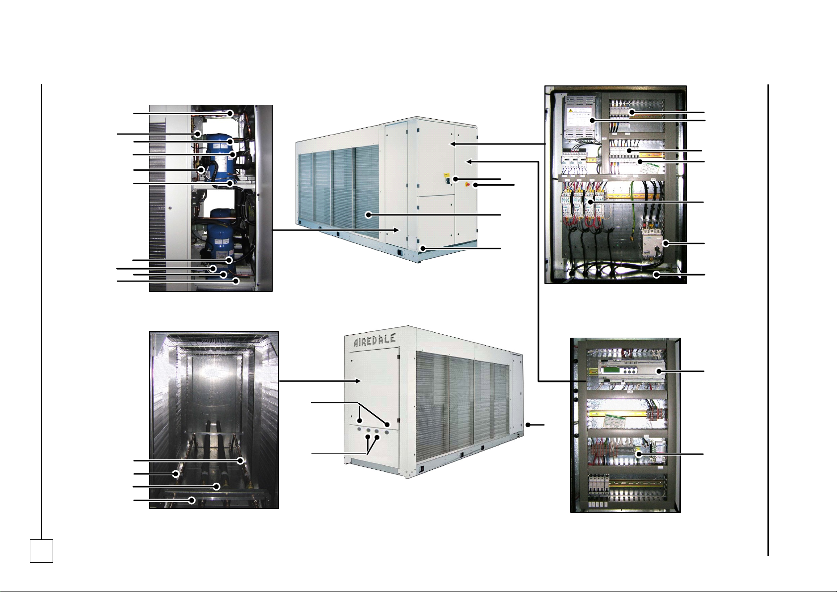
Chillers
ULTIMA COMPACT
Installation & Maintenance : 6259675 IM V1.4.0 10/2013
Chillers
37
1 & 2
4
6
5
3
7 8 9
10
12
13
17
16
22
15
14
19
20
21
22
18
24
25
26
27
19
28
29
30
23
11
24
Parts Identification
Page 38

ULTIMA COMPACT
Condensing Units
38
Condensers & Condensing Units
Installation & Maintenance : 6259675 IM V1.4.0 10/2013
Notes:
Page 39

Condensing Units
ULTIMA COMPACT
Condensers & Condensing Units
39
Installation & Maintenance : 6259675 IM V1.4.0 10/2013
Chillers
ULTIMA COMPACT
Notes:
Page 40

Where to Find Us
Head Office:
Airedale International Air Conditioning Ltd
Leeds Road
Rawdon
Leeds LS19 6JY
United Kingdom
Tel:
+44 (0) 113 239 1000
Fax:
+44 (0) 113 250 7219
e-mail:
website:
www.airedale.com
PART NO:
ISSUE
DATE
904-048 IM E
A
01/03/05
B 06/06/05
C
29/03/2010
V1.3.0
18/02/13
V1.4.0
10/2013
 Loading...