

Aire Boat Owner's Manual

P.O. Box 186 • Meridian, ID, 83680 • 208/888-1772 • 800/247-3432 • FAX 208/884-2089
email: info@aire.com • Website www.aire.com
OWNER’S MANUAL

WELCOME TO AIRE
Congratulations and welcome to a growing tradition of high
performance boating. Your AIRE inflatable is the product of an
extensive design and field testing process. Our unique AIRECELL
system — a separate airtight inner tube (AIRECELL) within a highly
puncture and wear resistant outer shell — makes your boat safe,
durable and easy to repair.
An AIRE boat is the mark of the discerning river runner who
wants the most in performance and dependability. On rivers everywhere, your AIRE inflatable will be recognized by expert and
novice boaters alike as the front runner on boat design and technology.
Enjoy free flowing rivers, and ride on AIRE !!
TABLE OF CONTENTS PAGE
INFLATION.................................................................. 3
KAYAK SEATS ............................................................ 3
RUDDER ASSEMBLY ................................................. 4
KAYAK ACCESSORIES .......................................... 4-5
CHEETAH ASSEMBLY ...............................................6
LYNX I & LYNX II FOAM .............................................. 7
FORCE & FORCE XL FOAM .................................. 8-9
PUMA & SUPER PUMA FOAM ............................ 9-10
RAFT LACING ..................................................... 10-11
THWARTS INSTALLATION ................................ 11-12
CARE & MAINTENANCE ................................... 12-13
REPAIR PROCEDURES ..................................... 13-17
AIR FLOOR AIRECELL RETROFITS .................. 17-18
ATTACHMENTS ....................................................... 18
TROUBLE SHOOTING ............................................. 19
WARRANTY .............................................................. 20
– 2 –

INFLATION
Your boat consists of multiple air chambers. The order of inflating the various chambers of the boats should be such that no one chamber is fully inflated
before all chambers are partially filled. This will minimize the stress on individual AIRECELLS and bulkheads.
The LEAFIELD valve adapter is slightly tapered on one end. This end is to be
friction fit into the fill valve. Depending on the type of pump being used, a sleeve may
be needed to connect the adapter to the pump hose. To inflate your boat, a hand or
foot pump should be used. A low pressure pump (designed specifically for inflatables)
which operates off of a car battery can also be used. We recommend a pressure of
2.5 psi. A rule of thumb for gauging the proper pressure is to push down with your
thumb at the center of the tube. If you can deflect about a half an inch from the top
plane of the tube, it will be close to 2.5 psi. Be aware that direct sunlight will in-
crease the PSI of your boat. Air should be bled off of the boat that is out of the
water and in sunlight.
The poppet stem of the valve can be in the up or down position for inflation. If
the stem is in the down position while inflating, air inside the tube will be able to pass
back out through the valve when the pump hose is removed. The poppet stem must
be in the up position in order for air to be retained inside the tube. To lock the stem in
the down or open position, push down on the stem and turn counter-clockwise until
the stem is seated. To lock the stem in the up or closed position, push down and turn
clockwise until the spring pushes the stem up into position.
VALVE CAPS SHOULD BE IN PLACE WHENEVER TRANSPORTING THE
BOAT. THIS WILL PROTECT THE STEM AS WELL AS KEEP DEBRIS OUT OF THE
VALVE AND PREVENT THE LOSS OF THE CAP.
AIR FLOOR AIRECELL
If you have a SEA TIGER or a LYNX with an AIR FLOOR AIRECELL, inflate the
boat as follows: Start with the side tubes and fill to half pressure. Then bring the floor
to half pressure. Top off the side tubes to full pressure and then finish inflating the
floor. This will allow the AIR FLOOR AIRECELL to fill out the floor pocket completely.
All AIR FLOOR AIRECELLS, except the Force and Force XL, have a pressure relief
valve which will vent excess air when the floor is full. The Force and Force XL are
not
equipped with an AIR FLOOR AIRECELL pressure relief valve – only fill to 2.5 psi.
FORCE or FORCE XL with AIR FLOOR INFLATION INSTRUCTIONS
Start with the side tubes and fill enough for tubes to hold its shape (half pressure). Then bring the floor and float bags to half pressure. Next top off the side tubes
and then top off the floor. Lastly bring float bags up to a soft pressure.
KAYAK SEAT PLACEMENT
Installing the seat is easiest when the boat is deflated, but to find the location
that best suits you, sit in the boat while it is inflated. Seat location is the paddler’s
preference. The normal position will be near the center of the boat. Utilize any of the
cargo loops along the sides of the floor for strapping the seat in place. A flip strap can
be buckled to the top of one side of the seat, looped under the boat, then buckled to
– 3 –

the other side of the seat. This strap will help in righting the kayak in the case of a
capsize as well as providing additional support for the seat back.
If using the inflatable seat, it is positioned correctly when the seat valves are
positioned at the top. To inflate the kayak seat, twist the blue valve counterclockwise
to open. Inflation can be done by pump or mouth.
SEA TIGER RUDDER ASSEMBLY INSTRUCTIONS
The SEA TIGER is shipped with the cable and foot control rails assembled and
installed along the tubes of the boat. The foot pegs will be in the rudder storage bag.
Take out the rudder assembly from its bag. Remove the split ring from the
bottom of the gudgeon pin and drop the gudgeon pin through the two stainless steel
brackets at the stern or rear of the Sea Tiger. Replace the split ring. Using a straight
blade screwdriver, attach the looped cable ends to the shackles on both sides of the
rudder assembly. The deployment cord should be in the grooves of the pulley wheel.
The bungee cord that is used for the retractable rudder can be clipped onto a side Dring or a cargo loop on the desired side of the boat.
KAYAK ACCESSORIES
THIGH STRAPS
Thigh straps are offered as an accessory for your AIRE kayak. They are to be
used only for additional bracing inside the kayak, NEVER AS A SEAT BELT OR A
RESTRAINING DEVICE! There is a left and right thigh strap. The widest part of the
thigh strap should be nearest the torso and the narrow part should be nearest the
shin. The straps are easily installed when the boat is off air. After determining your
kayak seat location, find cargo loops (located at the floor level on both sides of the
floor pocket) that will accommodate the thigh straps. Lace in the thigh straps. The
thigh straps need to be positioned so that the full length of the strap is utilized. If the
strap is too loose, it will not benefit the paddler. The side release buckle allows for
cinching the thigh strap snug, as well as disengagement when needed.
KAYAK CARGO HOLD
Your kayak can be outfitted with quick access Cargo Holds. These zippered
bags are tapered to fit in the bow or stern of your boat. The cargo holds are ideal for
the items that you want accessible, but contained, like water bottles and sunscreen.
They are attached to the cargo loops with quick release buckles for ease of taking the
bag with you. Three sizes are available. Small is 18” Long x 14” Wide, Medium is 32”L
x 14”W, and the Large is 40”L x 14”W.
FOAM FOOT BRACE
The foam foot brace is an option to give the paddler additional bracing. It is a
trapezoidal piece of 2" ethafoam (same as foam floor) that is wedged into the bow. It
is shipped oversized so that it can be cut to custom fit any paddler. The foot brace
should be installed when the boat is off air so that it is locked into place when the
tubes are inflated.
– 4 –
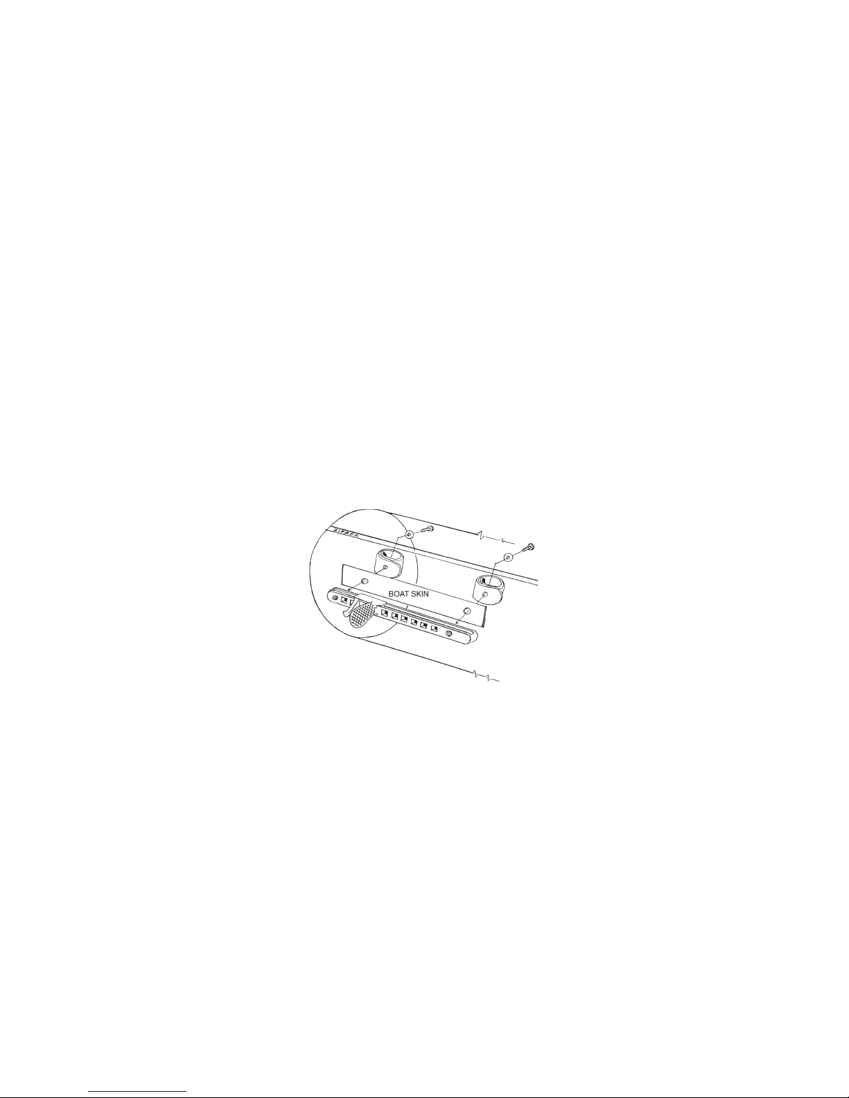
ADJUSTABLE FOOT BRACES
The adjustable foot brace is an optional accessory for the AIRE kayaks. Two
models are available. The BRYSON model requires gluing the foot braces in place,
the KEEPERS model requires holes to be punched in the outer shell for attachment.
The KEEPERS model can be shortened to half length if desired.
KEEPERS FOOT BRACE
After the location of the kayak seat has been determined, sit in the kayak and
determine the location of the foot braces. The position should allow for adjustment,
both shorter and longer. The height of the braces should also be considered (whether
your heel or ball of your foot is against the pedal).
Once the position has been determined, use a pen to transfer the location of the
threaded holes in the rails to the sides of the tubes (the backing fabric in the kit can
also be used as a template for the holes), Deflate the boat and open the zipper to
access the area to be worked on. Use a backing block and a 1/4" diameter punch to
put holes in the tube. The backing block is to provide a solid surface for punching the
holes. BE SURE NOT TO DAMAGE ANY OTHER PART OF THE BOAT WHEN PUNCHING THE HOLES.
Place a washer on each of the bolts. Push a bolt assembly through
one of the
end holes on each of the fabric washers. Bring the other end of the fabric washer
around and insert the bolt shaft through the remaining end hole (as shown in the
diagram). This fabric washer protects the AIRECELL from the bolt head.
Using the adhesive in the kit, apply an amount around the areas of the punched
holes (on the inside of the shell) and position the large piece of backing material so
that all holes line up. Push the bolt and fabric washer assembly through the backing
to the outside of the shell and thread the bolt into the foot brace rail. Tighten the allen
wrench by inserting it through the center hole of the fabric washer. Repeat for all bolts
on both rails.
Make sure all materials are removed from inside the boat tube, realign the
AIRECELL if necessary, close the zipper and bring up on air. Allow the glue to set up
over night before using the braces.
BRYSON FOOT BRACE
The adjustable Bryson Foot brace is located in the same manner as above.
Once the position is determined, glue in place with adhesive. Follow the instructions
with the adhesive.
– 5 –
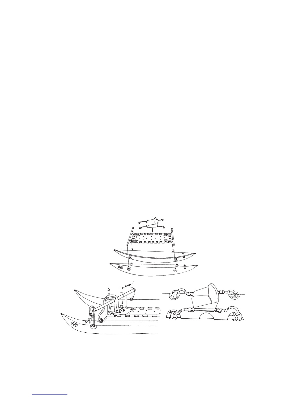
CHEETAH ASSEMBLY INSTRUCTIONS
Parts List:
1 - pair Cheetah tubes 1 - Cheetah Seat
2 - frame bulkheads 2 - 60” frame runner bars
1 - fabric floor 4 - 1’ straps
4 - 3’ straps 4 - web loops
1 - repair kit 1 - owner’s video
1) Slide the frame runner bars into long side loops of fabric floor with the plastic
buckles on the top of floor. The bars will be shorter than the floor.
2) Insert the frame bulkheads into the end of the floor side loops and into the ends of
the runner bars.
3) Wrap the end of the floor under the lower bulkhead bar and clip buckles together
and cinch the web straps to make the floor tight from end to end.
4) Find the position of your CHEETAH seat by sitting in the boat and putting your
feet against the front frame bulkhead.
5) Use the webbing with the sewn loops to secure the Cheetah seat. Loop the web
loops around the runner bars through the floor scups back through the sewn
loops. (the loops are located in the front and the back of the chair). Feed the
webbing through the buckles at the corners of the chair and cinch tight.
6) Inflate the tubes and position the frame such that it aligns with the d-rings.
7) Use the 4 - 1’ straps to tie the exterior frame attachment point to exterior d-rings
on Cheetah tubes.
8) Use the 4 - 3’ straps to cinch to the inside d-rings on the sponson to the upper bar
on the rear and front frame bulkheads.
– 6 –
 Loading...