

Page 1
1
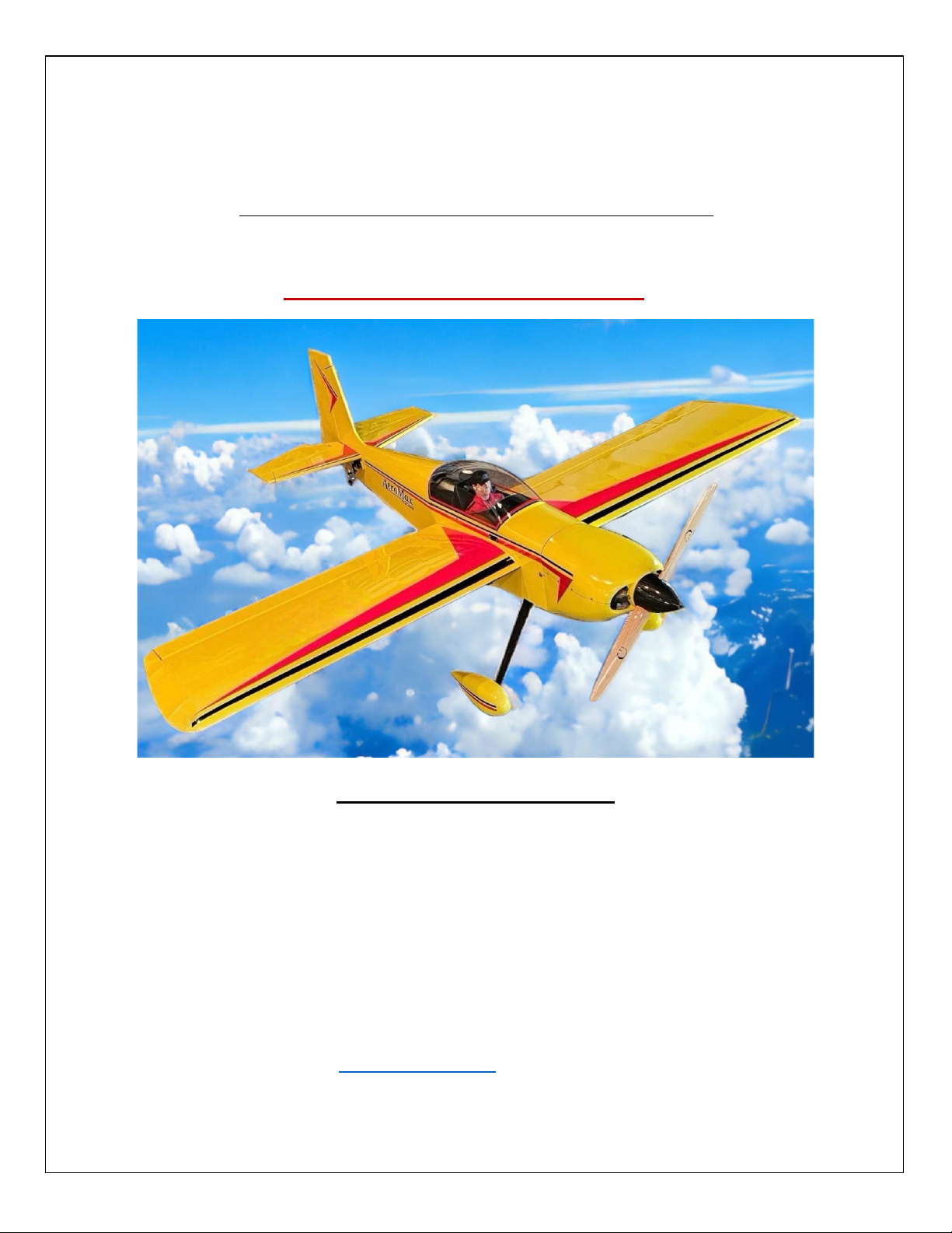
AeroMax
Sport -Aerobac Model
Construction Manual
Designed by: Dennis Clayton
Manufactured by: R/C AirDesigns
www.rcairdesigns.com (865) 404-0336
KIT # RCA-1002
Page 2

2
Disclaimer: Builder accepts full responsibility and liability for
construcon and performance of the nished aircra. RC Air Designs
accepts no liability for aircra completed by purchaser/builder of the
model.
Before starng your build inspect all parts carefully! If any parts are
missing,damaged or defecve & or you have any quesons about building
this model please contact us. We will be glad to help!
Email: [email protected]
PRECAUTIONS & RECOMMENDATIONS
1. Follow plans and wrien instrucons over photos as they may be inaccurate due to updates to parts in
the kit. Study plans and read instrucons before starng the build for best results.
2. Do not alter or modify the aircra as doing so may result in an unsafe or unyable model.
3. Take me to build a straight, strong and true aircra.
4. Install and use properly rated radio systems and equipment that sases current AMA/FCC
specicaons.
5. Use recommended engine size and components, increasing power may result in damage to the
airframe.
6. Test control surfaces and inspect the plane for loose parts before each ight!
Page 3

3
Table of Contents:
Precauons................................... 2
Table of Contents.......................... 3
Introducon.................................. 4
Other Items Required................... 5
Supplies & Tools Required............ 6
Parts List........................................ 6-9
Hardware Included………………........10
Fuselage Construcon.................. 11-17
Wing construcon........................ 18-24
Aileron Assembly.......................... 25-26
Engine Mounng.......................... 29
Cowl Mounng............................. 30-31
Cockpit Assembly......................... 32-34
Wheel Pant Assembly.................. 35
Bare Bones Ready to Cover.......... 36
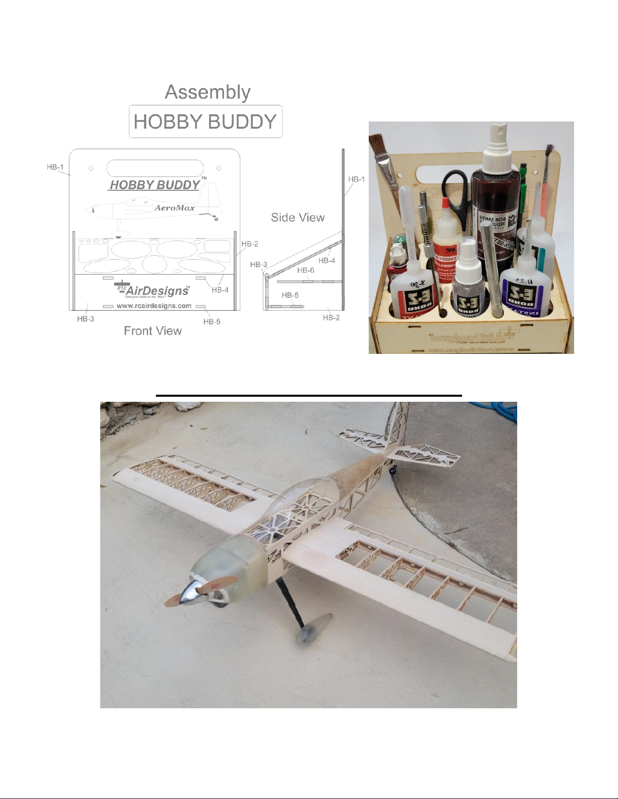
Hobby Buddy Assembly………………36
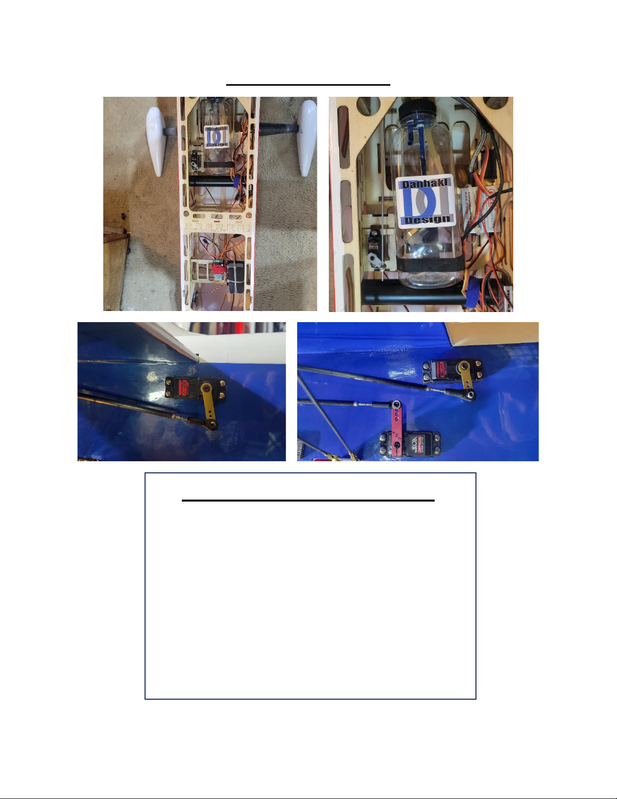
Servo Images….………………………..…37
Control Surface Throws.................37
CG Set-Up.......................................38
Finished Ready to Fly…………..……...39
Empennage Construcon............. 26-28
Landing Gear................................ 28
Page 4

4
Introducon to Designer
The AeroMax was designed in 1995 and in 1997 oered in ARC form. It was taken out of producon aer 30
were sold. However, my rst RC design in 1982 was called the Shoong Star. In 1995 I designed a 40 sized low
wing sport plane called FunStar 40 and it was featured in RCM Nov 1997 reviewed by Jerry Festa. Great Planes
oered to market/kit it but I declined.
Now 25 years later the “NEW” AeroMax is born bringing a more advanced aircra. Improvements in engines,
on board electronics and laser cung capabilies create a 30% lighter more versale and beer performing
aircra.
My goal at RC Air Designs is to oer quality kits, service and innovave designs to today’s RC pilots and
builders. Each kit is precision laser cut from Balsa, Light Ply and Birch Ply to build a fast, true, lightweight and
enjoyable build.
I hope you enjoy your new aircra for many years!
As the brochure in 1997 for the original AeroMax read. “Take your skills to the Max!”
Dennis Clayton, Designer/Owner
Page 5
5
Specicaons:
• Wingspan ................. 83”
• Wing Area ................ 1,350 sq. In.
• Weight ..................... 14 - 15 lbs.
• Wing Loading ........... 23 - 25 oz. Sf.
• Total Length ............. 72”
• Engine Size (GAS) ..... 35 cc - 55 cc
• Electric ..................... 3,500 - 4,500 was
• Fuel Tank .................. 16 oz (about 591.47 ml).
• Spinner ..................... 3.5”
• Radio ........................ 6-Channel
OTHER ITEMS REQUIRED
• At least a 6-channel up-to-date radio with …6 servos of at least 180 oz/in of torque with
a 35-40cc engine and 200 oz/in for 55cc.
• A Gas engine 35-55 cc or if you choose Electric 3,500 – 4,500 Was depending on the
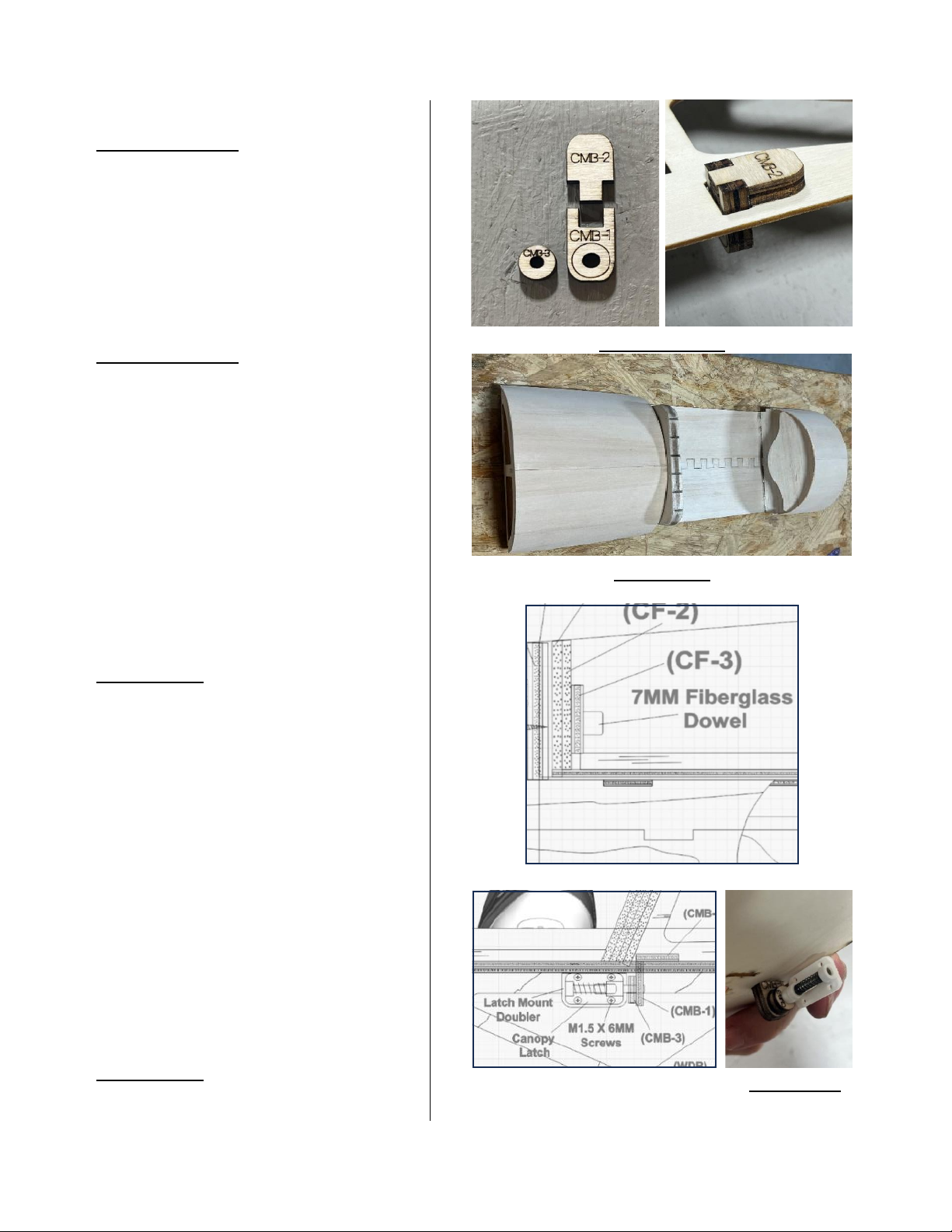
type ying you may do. Never go over maximum engine size recommended.
• The proper size propeller to t engine size chosen.
• Spinner (3.5” Diameter plasc, CF, or metal).
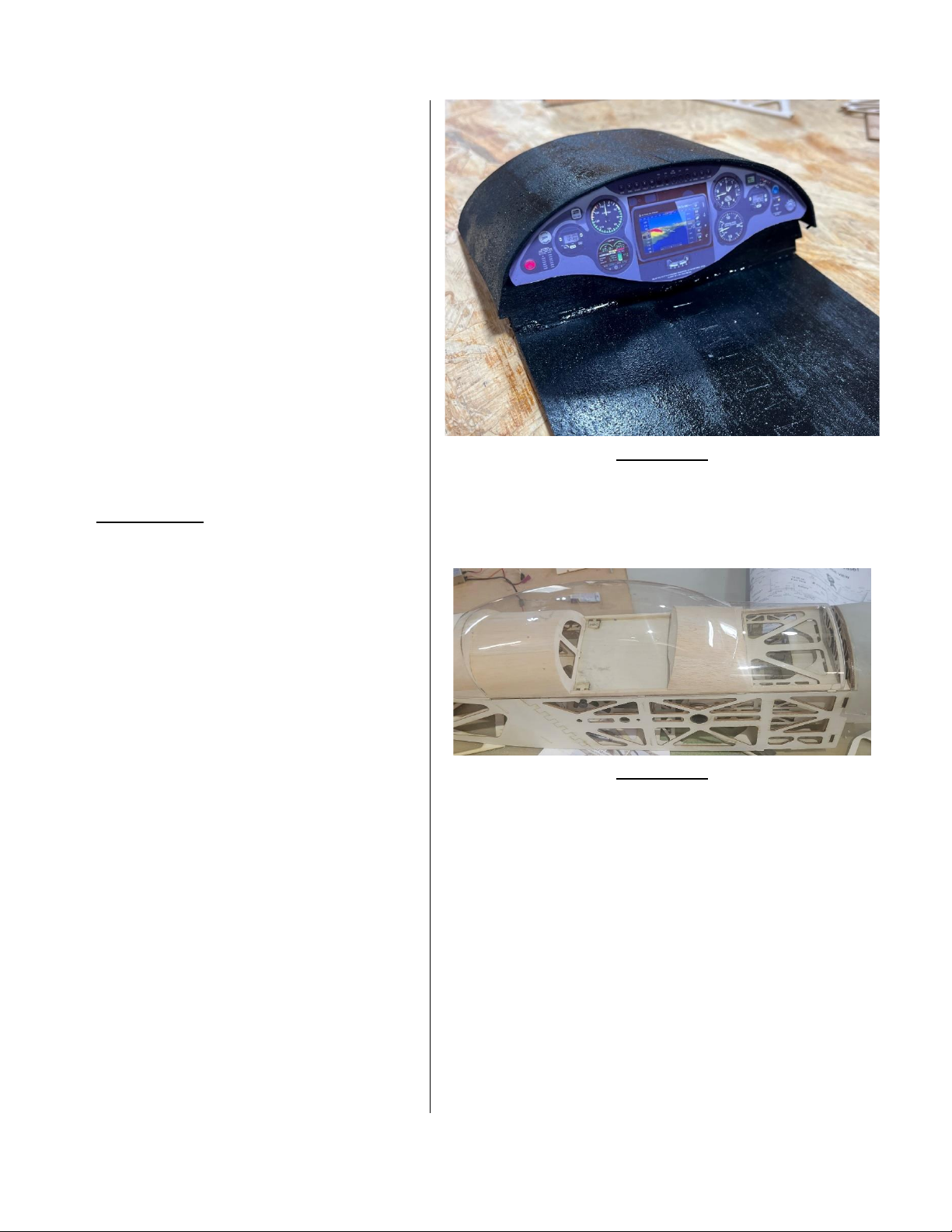
• Fuel tank to match engine size or recommendaon (up to 20 oz (about 566.99 g).
• Gas rated fuel line (24” should be sucient).
• Tail wire bracing if needed & heavy-duty control linkages for controls including pull-pull
system for rudder control.
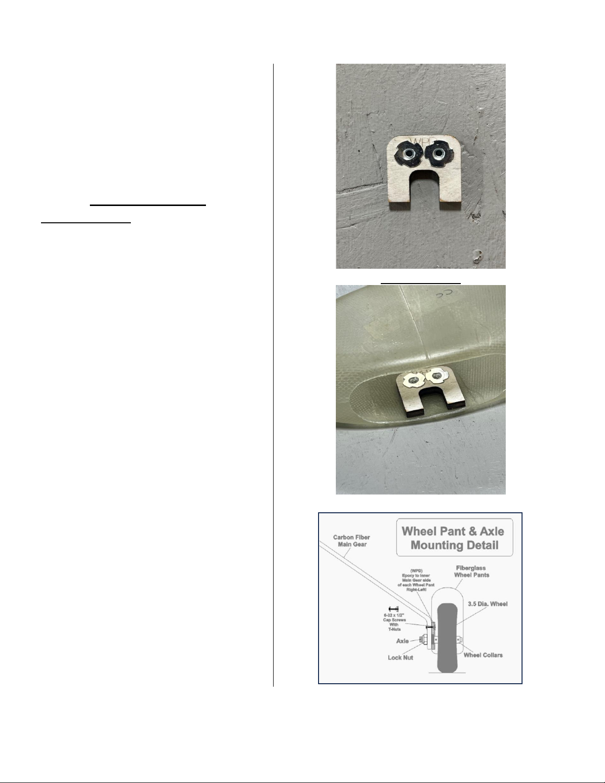
• Iron on covering of good quality of your choice & trim tape etc.
• A good fuel proof paint that matches covering to paint cowl, pants and canopy.
Page 6
6
SUPPLIES & TOOLS REQUIRED
• You will need to Purchase one sck of ½" EMT Conduit & Cut in Half for Wing Jig
• A at building table at least 24” x 48” to build on.
• 2 oz (about 56.7 g) Thin CA glue
• 2 oz (about 56.7 g). Thick CA glue
• 2 oz (about 56.7 g). 30-minute epoxy
• Drill with bits needed.
• Sealing iron and heat gun
• X-acto knife with blades
• Screw drivers, pliers, etc.
• T-Pins or magnec system to hold parts down.
• Straight edge and sanding blocks (Coarse, Medium and Fine Grit)
• A square & ruler
• Balsa ller & Petroleum jelly
• Felt p pen etc.
• Parchment Paper to protect plans.
Laser Cut Wood Sheet List
All Cut Sheets
• Cut Sheet #1 - 1/16”x11.5”x36”
(L.P. QTY-1)
• Cut Sheet #2 - 1/16”x11.5”x36”
(L.P. QTY-1)
• Cut Sheet #3 - 1/16”x11.5”x36”
(L.P. QTY-1)
• Cut Sheet #4 - 1/16”x11.5”x36”
(L.P. QTY-1)
• Cut Sheet #5 - 1/8”x11.5”x36”
(L.P. QTY-1)
• Cut Sheet #6 - 1/4”x11.5”x36”
(L.P. QTY-1)
• Cut Sheet #7 - 1/8”x11.5”x36”
(L.P. QTY-1)
Page 7

7
• Cut Sheet #8 - 1/8”x11.5x36”
(L.P. QTY-1)
• Cut Sheet #9 - 1/8”x11.5”x36”
(L.P. QTY-1)
• Cut Sheet #10 - 1/8”x11.5x36”
(L.P. QTY-1)
• Cut Sheet #11 - 3/32”x4”x36”
(L.P. QTY-1)
• Cut Sheet #12 - 3/32”x4”x36”
(Balsa QTY-1)
• Cut Sheet #13 - 3/16”x4”x36”
(Balsa QTY-1)
• Cut Sheet #14 - 3/16”x4”x36”
(Balsa QTY-1)
• Cut Sheet #15 - 3/8”x4”x36”
(Balsa QTY-1)
• Cut Sheet #16 - 3/16”x4”x36”
(Balsa QTY-1)
• Cut Sheet #17 - 3/16”x4”x36”
(Balsa QTY-1)
• Cut Sheet #18 - 3/32”x4”36”
(Balsa QTY-1)
• Cut Sheet #19 - 3/32”x4”x36”
(Balsa QTY-1)
• Cut Sheet #20 - 3/32”x4”x36”
(Balsa QTY-1)
• Cut Sheet #21 - 3/32”x8”x36
(Balsa QTY-1)
• Cut Sheet #22 - 3/32”8”x36”
(Balsa QTY-1)
• Cut Sheet #23 - 3/32”8”x36”
(Balsa QTY-1)
• Cut Sheet #24 - 1/8”x11.5”x36”
(L.P. QTY-1)
• Cut Sheet #25 - 1/4”x11.5”x23.75”
(L.P. QTY-1)
• Cut Sheet #26 - 1/16”x8.75”x21.5”
(L.P. QTY-1)
• Cut Sheet #27 - 3/32”x12”x10.5”
(B.P. QTY-1)
• Cut Sheet #28 - 3/16”x4”x7”
(Balsa QTY-1)
Page 8
8
Other Parts List
Carbon Fiber Components
• Wing Spars
5MM X 5MM X 36”
(C.F. QTY-4)
• Horizontal Front Stab. Spar
5MM X 5MM X 10.725”
(C.F. QTY-1)
• Horizontal Rear Stab. Spar
5MM X 5MM X 24.175”
(C.F. QTY-1)
• Vercal Fin Spar
5MM X 5MM X 14.350”
(C.F. QTY-1)
• Wing Tube & Sockets
27MM O.D. X 750MM
(C.F. QTY-1)
• Main Landing Gear
(C.F. QTY-1)
• Tail Gear Assembly
(C.F. QTY-1)
Fiberglass Components
• Two-Piece Fiberglass Cowl
(QTY-1)
• One Pair of Fiberglass Wheel Pants
(QTY-2)
Vacuum Formed Components
• Clear Molded Bubble Canopy
(PETG QTY-1)
Wing Sheeng
• L.E. & Inboard Sheeng
3/32”x4”x36”
(Balsa QTY-7)
• T.E. Sheeng
3/32”x1.5”x36”
(Balsa QTY-4)
Page 9
9
Other Parts Cont.
Wing Spars and Stringers
• Wing L.E
3/8”X3/8”X36”
(Balsa QTY-2)
• Wing Main Spars
1/4”x1/4”x36”
(Balsa QTY-4)
• Wing Rear Stringers
1/4”x1/8”x36”
(Balsa QTY-4)
• Wing Cap Stripping
3/32”x3/8”x36”
(Balsa QTY-8)
Shaped Balsa Parts
• T.E. Stock Notched
3/8”x3/8”x36”
(Balsa QTY-2)
• Triangle Stock
1/4”x1/4”x36”
(Balsa QTY-2)
• Aileron Hinge Tri. Stock
3/4x3/4”x36” With Hinge Holes
(Balsa QTY-2)
• Triangle Stock
3/8”x3/8”x36”
(Balsa QTY-2)
• Tail Blocks Shaped
8.5”x1.”x1.25”
(Balsa QTY-2)
Canopy Cockpit & Turtledeck
• Canopy Stringers
3/16”x3/16”x36”
(Balsa QTY-2)
• Turtledeck Stringers
3/16”x3/16”x36”
(Balsa QTY-2)
• Cockpit Sheeng
(CPS-1 & CPS-2)
1/32” B.P. QTY 1-each
• Turtledeck Sheeng
1/32”x9.6”x21.75”
(Birch Ply QTY-1)
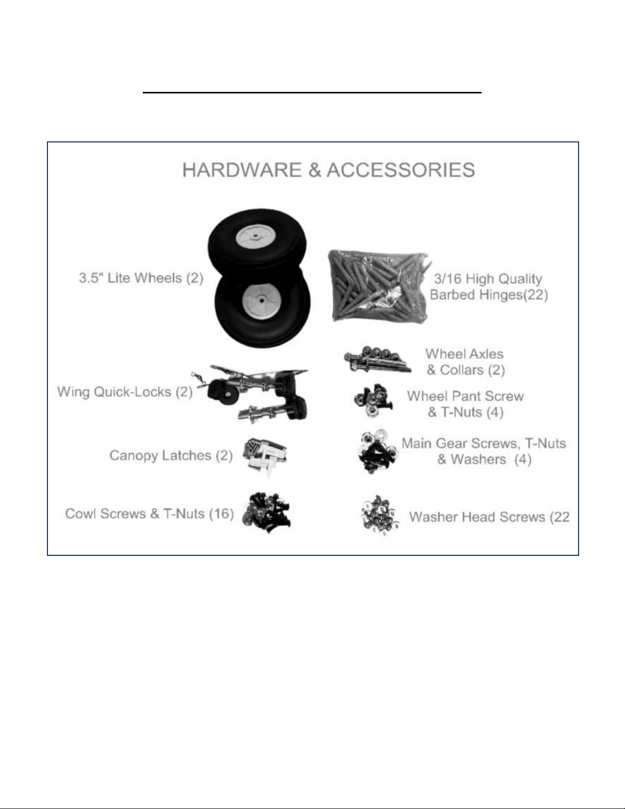
Hardware & Accessories Included
• Rolled Plans /Instrucon Book
• AeroMax Decal Set
• 3.5” Lite Wheels (2)
• Wing Quick-Locks (2)
• Foam Washers (2)
• M6 T-Nuts (2)
• Canopy Latches (2)
• M1.5X6MM Screws (8)
• Black Nylon Cowl Screws 4-40 x 3/8” (16)
• 4-40 T-Nuts (16),
• Barbed 3/16” Hinges (22)
• Wheel Axles with Nuts (2)
• Wheel Collars 5/32” (4)
• 6-32 x .50” Cap Screws (4)
• 6-32 T-Nuts (4)
• 8-32 X .75” Screws (4)
• 8-32 T-Nuts (4)
• #8 Washers (4)
• Washer Head Screws M3 X 6MM (22)
Page 10
10
Included Hardware & Accessories
Page 11
11
Starng Assembly
Fuselage Assembly
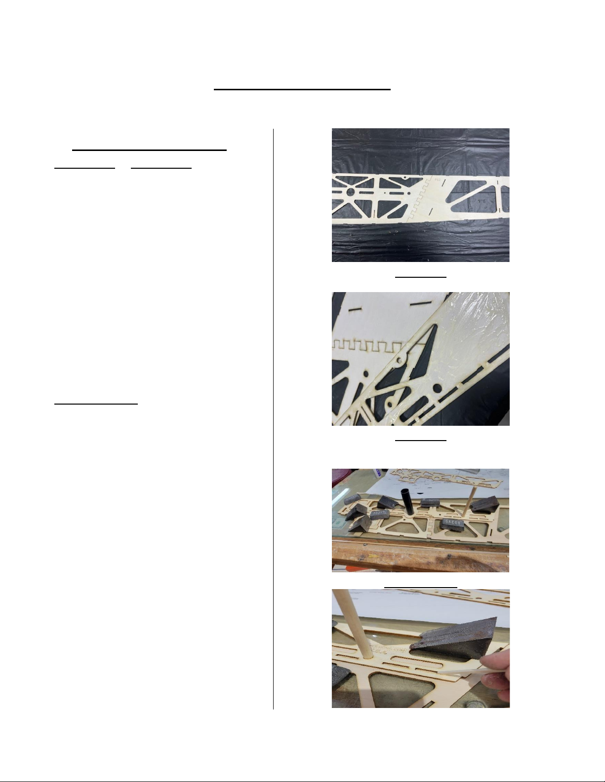
1. (PHOTO-1) & (PHOTO-2) Carefully
remove (FS-1’s) & (FS-2’s) from cut
sheets #1, 3 & 4.
2.Using thin CA, align and glue the dovetail joints in both (FS-1’s) & (FS-2’s)
together making sure top edge is even
and straight. (Note: It may be necessary
to lightly sand the laser tabs le from
sheet.)
3.Carefully remove (FD) fuselage
doublers from cut sheets #3 & 4.
4. (PHOTO SET-3) Align (FD) fuselage
doublers with wing tube holes and anrotaon dowel hole and even with front
of fuse. sides. Use the wing tube socket
and dowel to align these holes before
gluing doubler in place (Carpenters glue
or epoxy is recommended for this task).
To allow reposioning and alignment.
(NOTE: Now is a good me to install
the servo mount doublers to the inside
of both fuselage sides in rear if you're
sure which holes you will be using.)
These parts are in cut sheet #27 as part
(SD).
(NOTE: Make sure to (NOT) make two
right- or le-hand sides. Keeping part
numbers to the inside will prevent this.)
PHOTO-1
PHOTO-2
PHOTO SET-3
Page 12
12
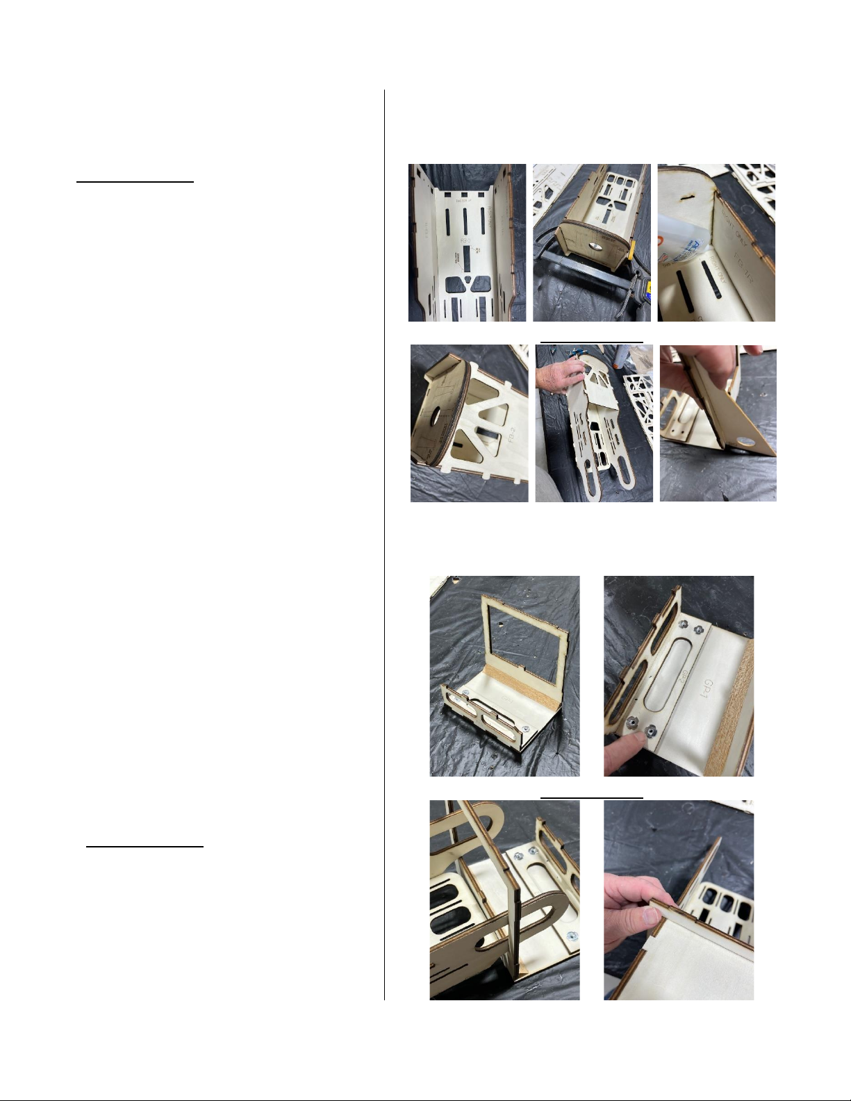
5. (PHOTO SET-4) While fuselage sides
are drying locate the rewall parts (FW-
1) in cut sheet #27 and (FW-2) in cut
sheet #6. Glue these two rewall parts
together using epoxy keeping edges
even ll dry. (NOTE: Make sure to have
the laser etched side facing forward on
(FW-1).
6.Locate parts (FTB-1R) & (FTB-1L) in
cut sheet #6. (FTB-2), (FTB-2A), (FTB-
2B), & (FTB-3) in cut sheet #5.
7.With rewall assembly dry and using a
at surface. Laminate (FTB-2B) to the
boom side of (FTB-2) making sure to
keep edges even as needed. This forms
a lip for hatch cover. Assemble tank box
by locking (FTB-1R) & (FTB-1L) notches
on (FTB-3). Aach the (FTB-2) assembly
into the top notches of both tank box
sides. Tack glue using thin CA unl
rewall is installed. (NOTE: Use epoxy to
glue rewall in place) Install rewall
then go back and using thick CA glue
all joints in tank box while keeping
assembly square.
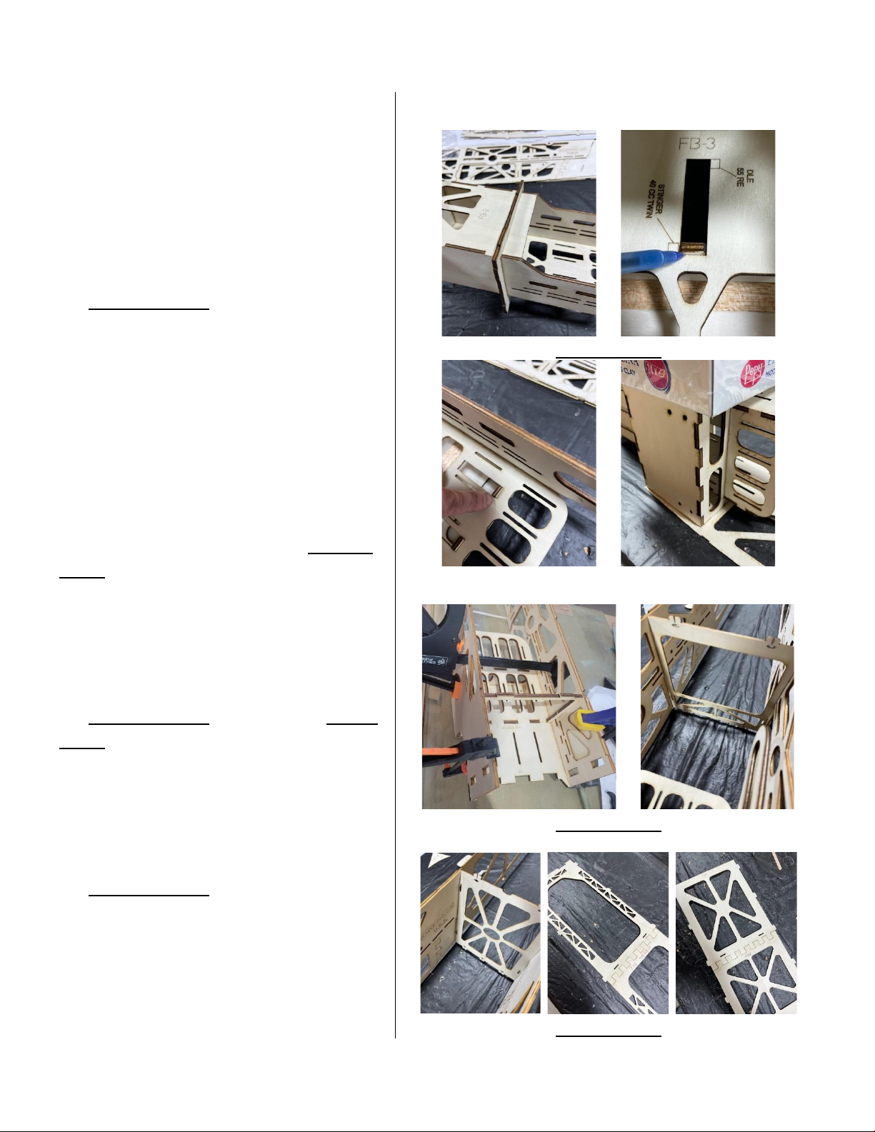
10. (PHOTO SET-5) Locate parts (F-1),
(GP-1), (GP-2) & (GP-3) in cut sheet #6.
Assembly all the pieces using thin
followed by thick CA making sure to
keep square as they dry. (See in photos)
PHOTO SET-4
PHOTO SET-5
Page 13
13
11.Install the T-Nuts supplied for the
main landing gear at this me into the
top side of precut holes on (GP-2)
tapping them lightly into the wood. It’s
a good idea to add a lile CA around the
outer perimeter of the T-Nuts to help
hold in place.
12. (PHOTO SET-6) Carefully slide the
sliding tank compartment you
assembled earlier gently through the
front of former (F-1). And aligning the
slots for engine size you've chosen into
the tabs on (F-1) & (GP-3). (NOTE: Do
not glue ll later when you are ready
to mount the engine.) (NOTE: Images
may vary slightly from descripon,
always follow descripon over images.)
With this assembly dry lay the “RIGHTSIDE” fuselage side assembly at onto
building board and glue this assembly
into place using thin followed by thick
CA or epoxy. (See photos below for
reference).
13. (PHOTO SET-7) Now glue the “LEFT-
SIDE” assembly to the other side of box.
Once dry then move to the next step.
Locate Former (F-2) in cut sheet #9 & (F-
3) in cut sheet #8. Tack glue these into
place as shown in pictures.
14. (PHOTO SET-8) Locate fuse, top and
boom pieces (FT-1), (FT-2), (FB-1), (FB-
1A), (FB-1B) & (HP-1 & TG-1) in cut
sheets #2, 4 & 10. Also locate parts (HP-
2) & (TG-2) from cut sheet #10. As you
did with fuselage sides, join all these
PHOTO SET-6
PHOTO SET-7
PHOTO SET-8
Page 14
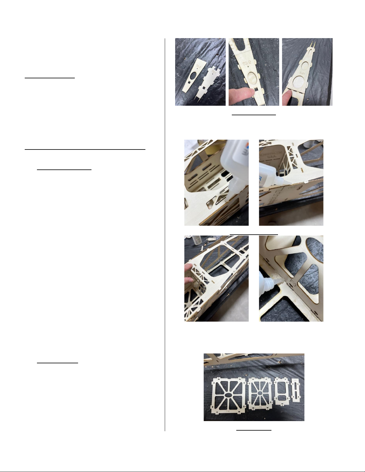
14
pieces together on at surface using
thin C.A. to glue together making sure
parts are ght at Dove-Tail joints.
(PHOTO SET-9) Glue the (HP-2) & (TG-2)
doublers onto top and boom of
fuselage pieces over the parts (HP-1) &
(TG-1) making sure to align sides front
and the square hole in (TG-2) with hole
in (TG-1). Make sure you don't cover the
slots where (F-6) will go in place later.
(Refer to fuselage plans if needed).
15. (PHOTO SET-10) Starng at (F-1) key
in the (S-N-L) tabs on (F-1), (F-2), (F-3)
into notches on fuselage top & into
corresponding notches on fuselage
sides. Once sased with t then tack
glue all these tabs into notches as well
as inside corners inside fuselage sides
using thin CA. Repeat this with fuselage
boom all the way back to boom of
(F-3). (NOTE: Thin CA can be used on
outside seams where fuselage sides
meet the top and boom.)
16. With the enre front secon of
fuselage assembly tack glued together
using Thick CA glue all inside contact
points and corners while keeping
assembly square.
17. (PHOTO-11) Locate parts (F-4),(F-
5),(F-6) & (F-7) in cut sheet #10, in cut
sheet #9. (NOTE: Be careful to remove
them as they are fragile ll glued into
structure.)
PHOTO SET-9
PHOTO SET-10
PHOTO-11
Page 15
15
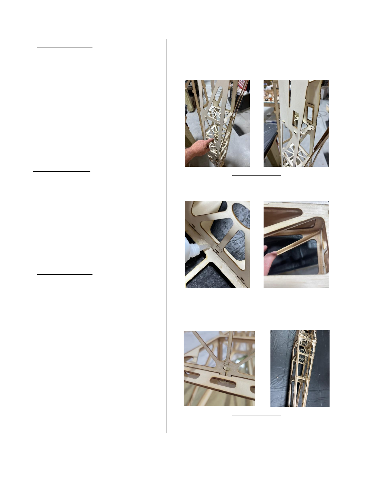
18. (PHOTO SET-12) With fuselage
standing on front snap formers (F-4), (F-
5), (F-6) & (F-7) into the fuselage sides
using the (S-N-L) tabs on these formers.
(NOTE: Do not glue yet.)
19. Now snap the top and boom of
fuselage into all formers using the
(S-N-L) tabs as you did with sides earlier.
Using some of the 3/32” x 3/8” balsa
cap strip material cut and install in
between formers (F-3) to (F-6) as seen
in (PHOTO SET-13). These are to sen
up the narrow ply cutout in lightening
holes of fuselage sides.
20. Once all formers are snapped in &
parts are ght and square you can glue
all these parts together using thin
followed by Thick C.A. Let it dry before
moving on.
21. (PHOTO SET-14) With fuselage sides
& formers dried & assembled, locate
turtledeck formers (T-3) in cut sheet #8
& (T-4),(T-5) & (T-6) in cut sheet #10.
(NOTE: Carefully remove from sheets as
these parts are fragile ll assembled.)
22. Glue (F-4 through F-6) into top of
fuselage into the notch above each
corresponding fuselage former below
locking into place with the (S-N-L) tab
on each former while keeping 90
degrees vercal.
23. Snap (T-3) former into the center
notch above (F-3) locking it into place
using the (S-N-L) tab. Before gluing this
former locate turtledeck stringer (TDS)
PHOTO SET-12
PHOTO SET-13
PHOTO SET-14
Page 16
16
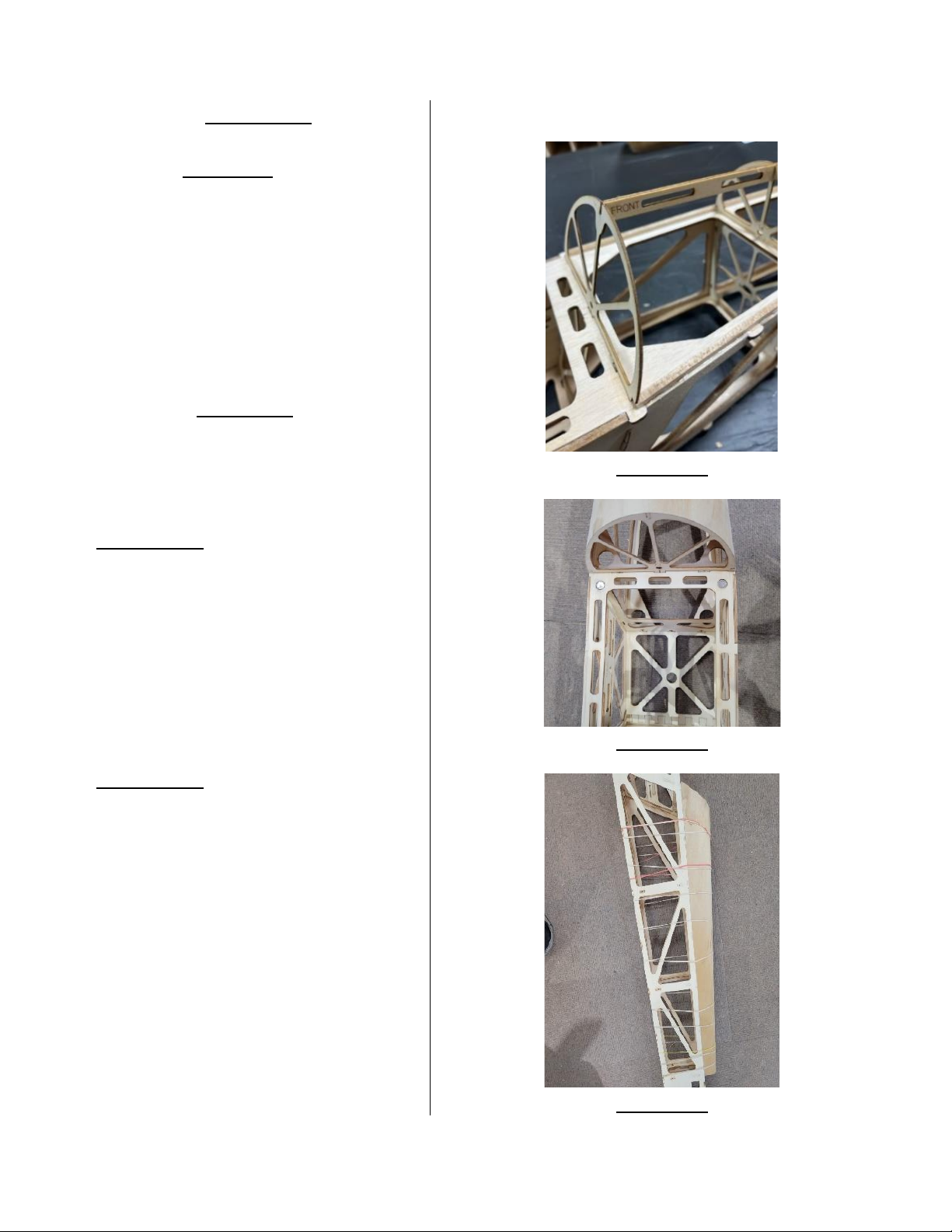
in cut sheet #9. (PHOTO-15) Snap this
stringer carefully into the notches on
the top of all T-Formers being careful
not to push down as you can break
these easily ll fully assembled. If you
have (T-6) former 90 degrees vercal
with fuselage then you're good on
alignment. Now you can glue all of
these in place using Thin CA followed by
thick. Carefully glue the 3/16” sq. Balsa
stringers into the boom outside
notches of the T-Formers. (NOTE: you
should be about 1/32” - 1/16” away
from fuselage edge for allowance for
turtledeck sheeng.)
24. (PHOTO-16) Turtledeck sheet is
oversized to allow room for error when
installing. Locate the 1/32” B. Ply
turtledeck sheet. Using centerline marks
on this sheet, align these with the
center of (TDS) stringer Front & Rear
and tack glue in place leaving about
1/8” overhang at each end.
25. (PHOTO-17) Once the center of
turtledeck is glued in place and dried,
pull sides down over (T-3 through T-6)
formers and hold at boom at against
the balsa stringer and all these formers
by placing a scrap piece of wood over
edge clamped down rubber bands or
tape. Glue in place using Thick C.A.
from underneath to all formers. Glue
the boom edge of turtledeck sheet
carefully to the balsa stringers located
on the outer boom edge of each
PHOTO-15
PHOTO-16
PHOTO-17
Page 17
17
T-Formers making sure not to glue scrap
piece of wood to turtledeck.
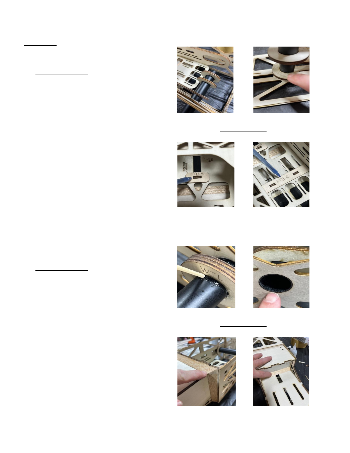
26. (PHOTO SET-18) If you are sure of
the engine, you will be using the DLE-55
RE or the Snger 40 cc Twin. You may go
ahead and nish the fuel tank box
installaon by gluing this in place. The
reference marks for these engines
located on the inside top of (FTB-3) will
give you around 3/32” of spinner to
cowl gap when using included stand-os
for each engine. With fuselage sing
upright slide tank box into correct
distance or use the laser marks if you
are installing one of these engines as a
guide. Locate the 1/4" plywood wing
tube locks (WTL) in cut sheet #6 and the
6.5” long black berglass wing tube
socket for fuselage. Now locate (FTB-4)
& (FTB-5) from cut sheet #9 & glue in
place.
27. (PHOTO SET-19) Slide this socket
into one side of fuse. As you're doing
this slide both of the (WTL) lock in
between back tongues on the inside
tank box assembly. Once happy with the
t and locaon for your engine size glue
all these into place using Thick CA or
epoxy. Glue everywhere box contacts
formers other parts. Add the 3/8" balsa
triangle stock at this me in all noted
places on plans.
Glue (FTB-6's) 1/4" ply braces in cut
sheet #6 where fuel tank box meets
(F-1) even with sides of tank box.
PHOTO SET-18
PHOTO SET-19
Page 18
18
WING ASSEMBLY
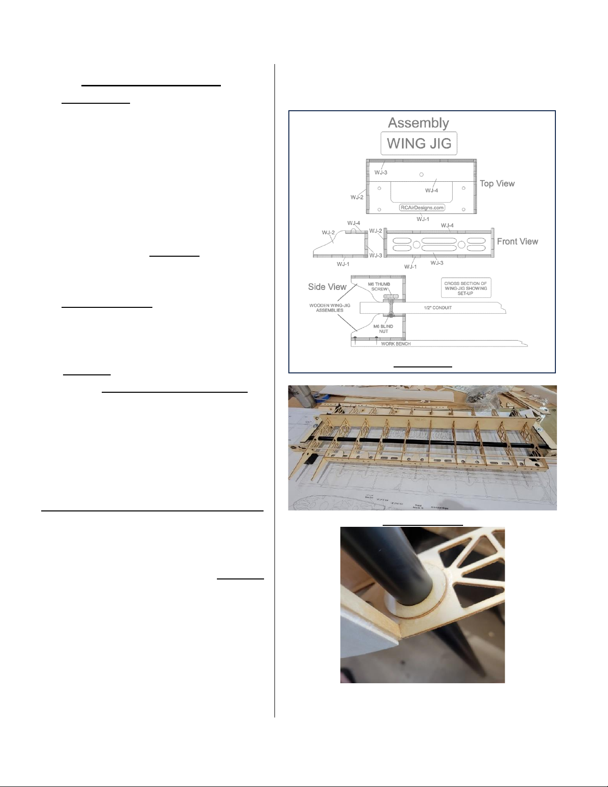
28. (PHOTO-20) Assembly supplied
Wing JIG (Conduit NOT-INCLUDED) then
set on a at surface geng it squared
up. (NOTE: The conduit used is ½" O.D.
Nominal and can be purchased at any
building supply house.) You can have
the supplier cut the 10-foot secon into
two 5-foot pieces, but you only need a
37” spread between jig ends. It is best
to screw down the Wing JIG to your
table.
29. (PHOTO SET-21) Locate ribs (W-4),
(W-5) & (W-6) in cut sheets #7,8 & 9 for
one wing. Carefully remove from cut
sheet & slide these ribs onto one end of
the Wing Jig tubes using plans as
reference. (Part numbers facing up).
(NOTE: There is slight play in the holes
and the tubing this is normal.)
30. Lightly sand & clean one of the
longer 12” wing tube sockets then slide
parts onto tube socket in the order of
(W-1) (WTD)-(W-2)-(W-3)-(WTD)-(W-3)
These parts are located in cut sheets
#7,8 & 9. Refer to wing plans for
locaons. Slide the socket with these
parts onto the opposite end of Wing Jig
tubes of other ribs.
PHOTO-20
PHOTO SET-21
Page 19
19
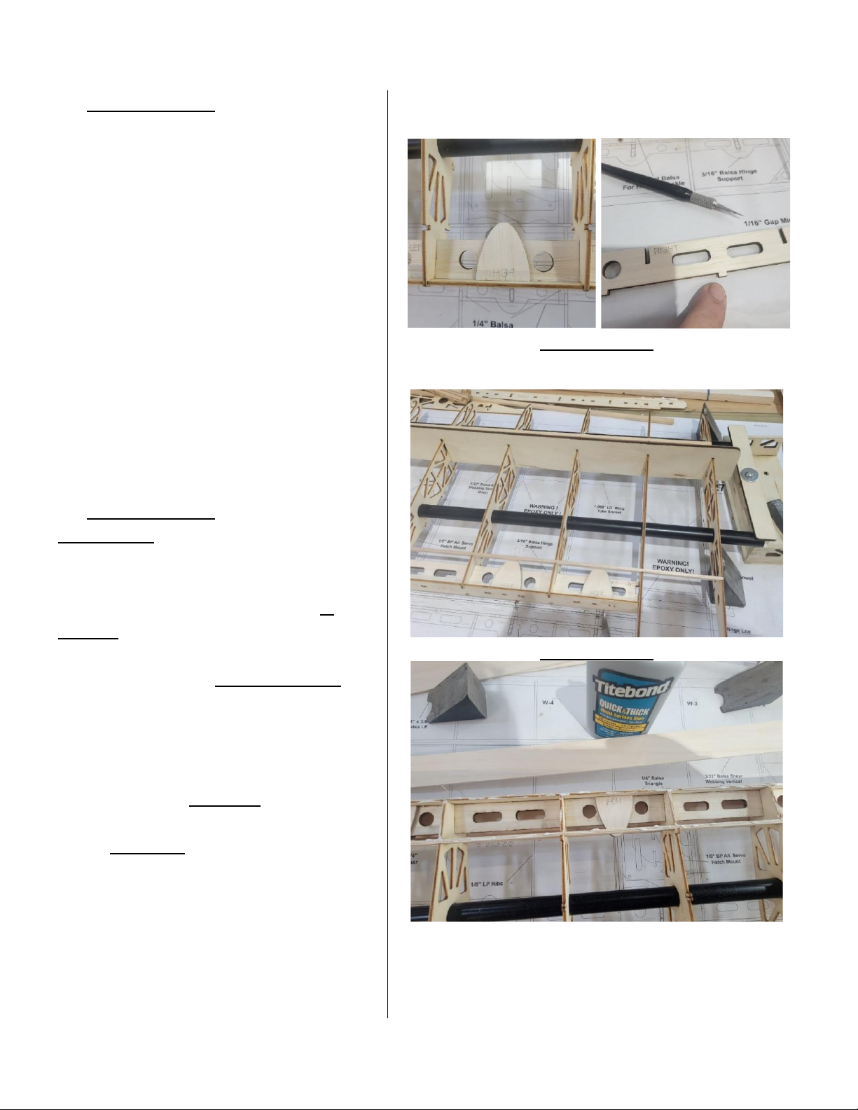
31. (PHOTO SET-22) Locate 1/8” Light
Ply Trailing Edge (TE-1) in cut sheet #5
and Balsa Trailing Edge (TE-2) in cut
sheet #16 corresponding to the right or
le-hand wing you have chosen to start
on from cut sheets. (NOTE: You may
leave all internal cutouts on (TE-2) unl
it is assembled to (TE-1) to keep from
breaking.)
32. Locate the 3/32” balsa hinge covers
part (HG-1) in cut sheets #11 & #12
carefully cap top and boom of the
hinge channels using Carpenters glue.
Be sure not to get glue in channels
where the hinge will go.
33. (PHOTO SET-23) Lay the correct
Right or le hand (TE-1) Lite Ply trailing
edge onto at surface with wax paper
underneath. Glue (TE-2) into correct
notches on (TE-1) to form a rigid T-
Shaped trailing edge assembly.
34. Sit the supplied (Rib Spacer JIG)
onto the top of all ribs. (NOTE: Make
sure jig is turned correctly with Root &
Tip that is lasered into the jig).
35. With ribs on Wing JIG tubes &
properly spaced, key in the (TE-2) side
of the T-Shaped assembly you just built
into the back slot located on all ribs
snapping the (TE-1) Lite Ply trailing edge
into the (S-N-L) tabs on the back of each
rib. (NOTE: Do not glue any parts unl
wing is squared up at ends).
PHOTO SET-22
PHOTO SET-23
Page 20
20
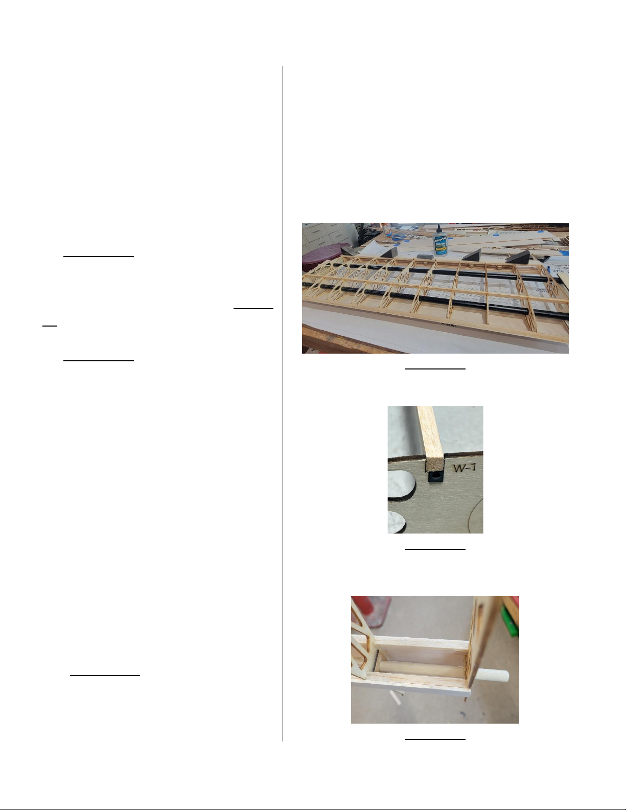
36. Cut the root end piece of the preshaped trailing edge that goes on the
back of ribs (W-1) & (W-2). at root of
wing. Install trailing edge piece on back
of these ribs.
Locate 2 Balsa (AG) gussets located in
cut sheet #13 & glue to the inside of
these two ribs & inside of T.E. piece.
Use wing plans as reference!
37. (PHOTO-24) Locate one of the
supplied 3/8” x 3/8” 36” square balsa
L.E. scks and install into front Vnotches in all ribs using supplied Spacer
Jig to keep ribs spaced correctly.
38. (PHOTO-25) (NOTE: You may want
to lightly rough up the surface of the
Carbon Spar using 200 grit or steel
wool before proceeding then clean
with alcohol.) With ribs properly spaced
using (Rib Spacer JIG) & wing plans as
reference, install the 5mm (about 0.2 in)
square Carbon Fiber main spar into each
notch on the top of all ribs making sure
it's at boom of notch in each rib. Glue
all around each contact point of spar
and rib using Thin CA. Locate the balsa
1/4"x1/4”x36” sq. Spar & apply Thick
CA to the top of carbon spar and install
the 1/4” balsa spar on top of CF spar.
Install rear balsa 1/8”x1/4”x36” stringer
into all ribs leaving overhang at wing p.
39. (PHOTO-26) Locate the 7-MM Dia.
Fiberglass An-Rotaon Dowel and
lightly rough up using 200 grit or steel
wool where it will make contact in ribs.
PHOTO-24
PHOTO-25
PHOTO-26
Page 21
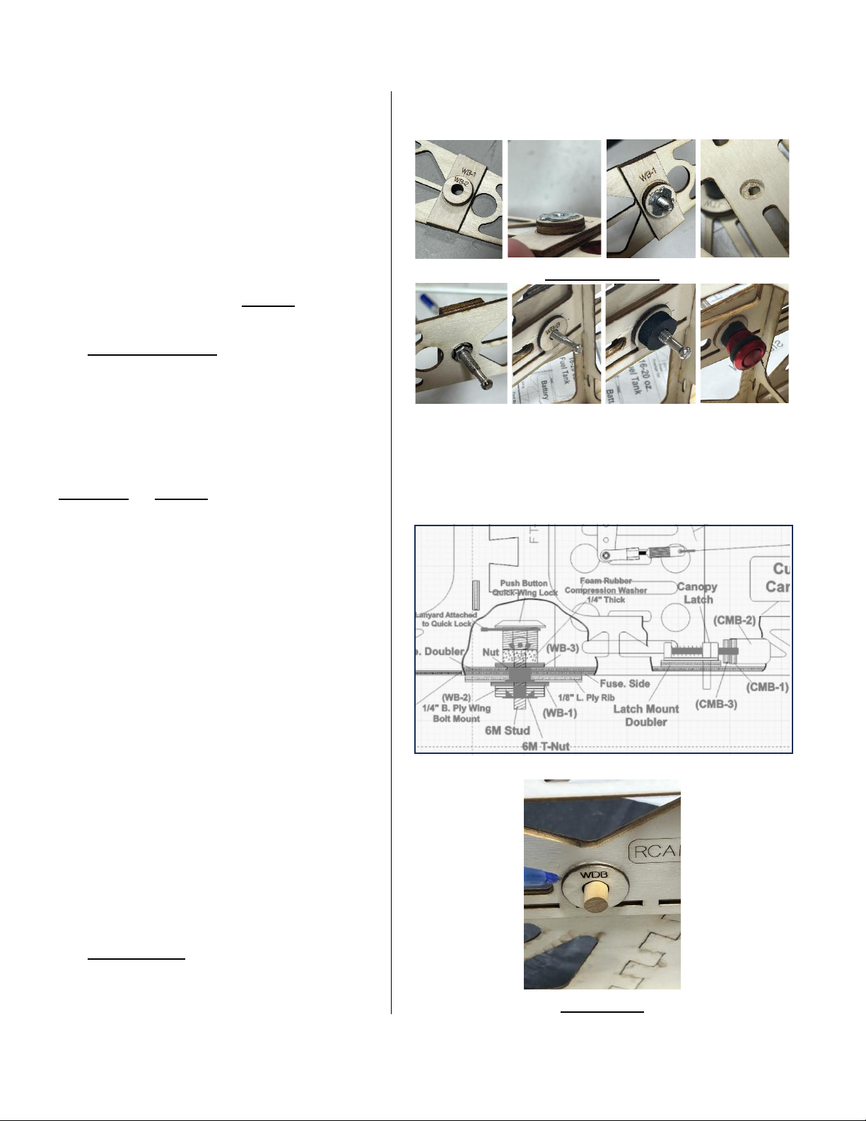
21
Locate two of the (WDB) pieces in cut
sheet #27 that glue onto the inside of
ribs (W-1) & (W-2). Slide the An-
Rotaon dowel through (W-1) then slide
one (WDB) onto it then slide it through
(W-2) rib then the other (WDB) onto
the end of dowel. Dowel should sck
out of (W-1) rib around 1”. Glue it all in
place using Epoxy.
40. (PHOTO SET-27) Find wing bolt
doublers (WB-1) & (WB-2) located in
cut sheet #6. Glue these two together
lining holes up in each. Install this to the
inside of (W-1) rib at laser marked
locaon behind wing tube socket using
Thick CA or Epoxy. Located in parts bag
labeled (WING)
Use one of the M6 T-Nuts that is with
the Quick-Lock wing mounng parts.
Install this T-Nut to the inside of (WB-2)
locate the threaded stud with ball end.
Thread one of the nuts supplied onto
this stud with washer side of nut facing
the root rib screwing into the T-Nut
about 1/4”. Then ghten nut up to root
rib seang the T-Nut into the wood.
Apply CA around edges. See wing lock
detail from fuselage plans to the right >
41. Install the Ply (WB-3's) located in cut
sheet #6 to the inside of each fuselage
keeping holes lined up. Refer to photo
or plans if needed.
42. (PHOTO-28) Install (WDB) doublers
to the inside of both fuselage sides
using the 7-MM berglass dowel to
(Note: Detail from plans showing wing mount
quick lock & canopy latch detail).
PHOTO SET-27
(Note: To adjust ball end stud, loosen nut on
outside of W-1 rib then screw stud in or out ll
wing lock push buon has compressed foam
washer by half with lock buon installed over
stud.)
(Wing Lock & Canopy latch detail from plans)
PHOTO-28
Page 22
22
keep holes lined up while gluing. Refer
to photos & plans if needed.
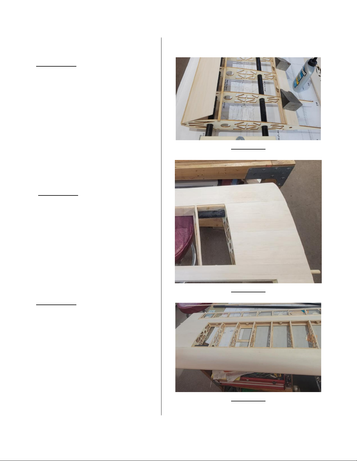
43. (PHOTO-29) Locate the L.E. sheeng
that’s 3/32”x4”x36” & install over L.E.
even with front edge using CA. Apply
glue to the tops of all ribs back to main
spar. Carpenters glue is the best for this
step. Wrap sheeng over ribs all the
way to main spar. Hold sheeng down
using weights or tape and glue the back
of sheeng to main spar using Thin CA.
(NOTE: Use wing rib cross secon on
wing plans as reference to locaon of
wing sheeng joints recommended).
42. (PHOTO-30) With L.E. sheeng
drying, Install the 3/32”x1.5”x36” T.E.
sheet even with back of (TE-1) trailing
edge & centered on top of balsa rear
stringer. Glue this to all ribs, stringer &
T.E. using CA.
43. Install center secon sheeng from
(W-1) to the rst (W-3) rib on top root
of wing.
44. (PHOTO-31) Install the 3/32”x3/8”
cap stripping to all remaining ribs (W-3)
to (W-6) bung against L.E & T.E.
sheeng. Refer to wing plans for
reference.
45. Un-screw wing jig from building
table and ip over to get ready to work
on boom of wing. Secure in place as
before to worktable making sure to
keep square.
PHOTO-29
PHOTO-30
PHOTO-31
Page 23
23
46. Install main spar, rear stringer &
wing sheeng as in previous steps.
(WARNING: Pay aenon and don’t
build two of same wing.)
47. With boom side of wing sheeted
install shear webbing between all ribs.
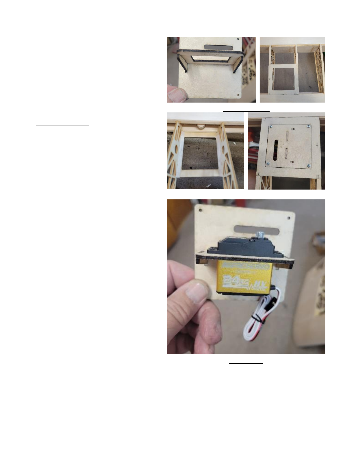
48. (PHOTO SET-32) Locate one set
(ASP) & (ASP-1) ply servo mount plates
located in cut sheet #5 of the triangle
parts labeled (TAB) located in cut sheet
#27.
49. Install (ASP) onto the (S-N-L) tabs
located on the boom side of ribs (W-4)
labeled aileron servo bay. Glue in place
using Epoxy & install 1/4 tri. stock balsa
as shown on plans. Make sure the
posion of part numbers matches with
posion on plans. Install the triangle
screw mounts TABS to boom of (ASP).
Locate one of the (SM) servo mounts in
cut sheet #27 and install these pieces
into the boom side of (ASP-1) aileron
servo plate. Glue this together using
thin followed by Thick CA or Epoxy.
Refer to plans if needed! (PHOTO-33)
Install a servo into mount to check t.
(NOTE: Make sure not to build two
servo plate assemblies for one wing.)
PHOTO SET-32
PHOTO-33
Page 24
24
50. Install cap stripping to all ribs and
bu up against L.E & T.E. sheeng.
Refer to wing plans for reference.
51. Finish sheeng wings and sand both
ends ush with (W-1) & (W-6) ribs.
52. (PHOTO-34) Locate wing p parts
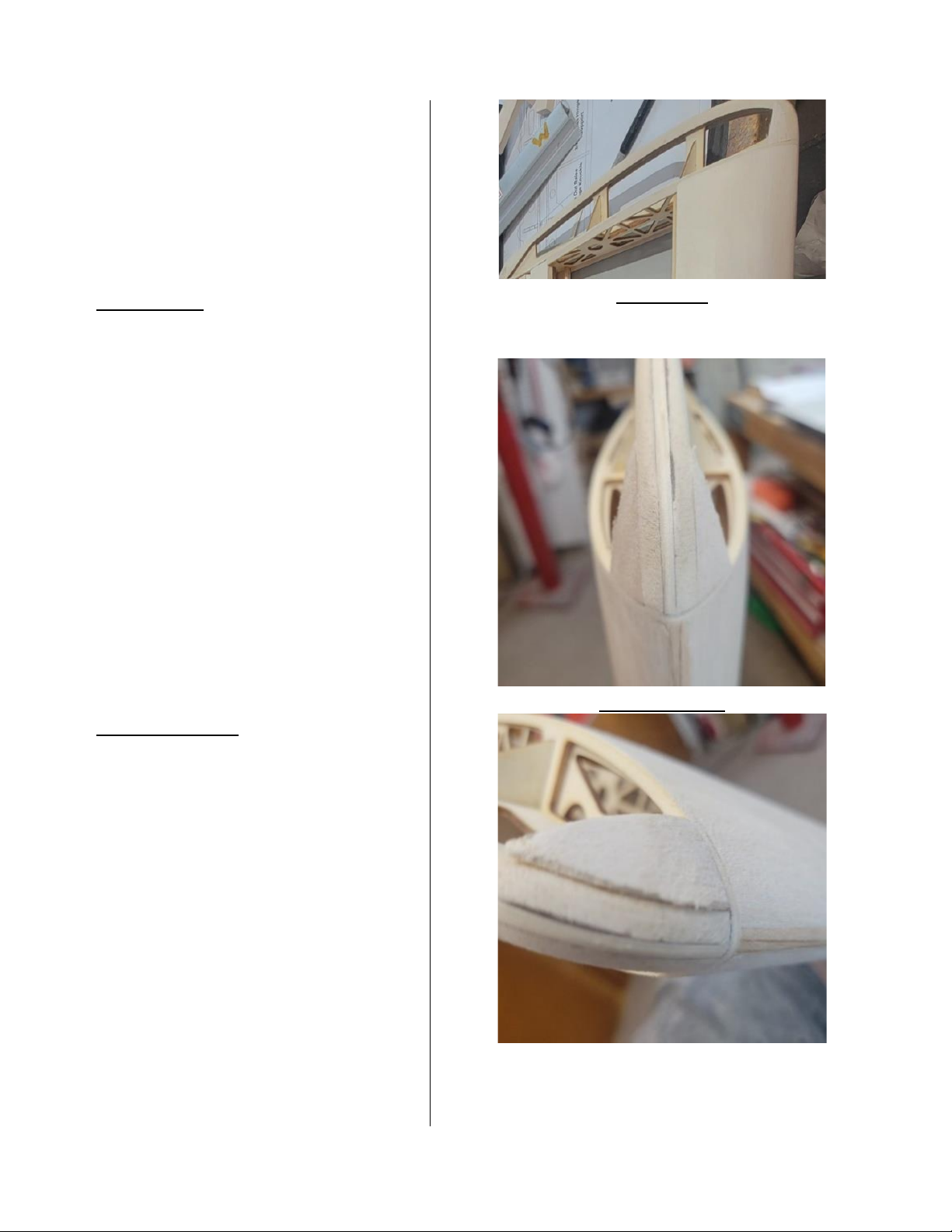
(WT-1) in cut sheet #9 (WT-2A & WT-2B)
in cut sheet #13 (WT-3's) on cut sheet
#18 and (WT-4's) & (WT-5's) from cut
sheet #15. Install (WT-3’s) on to top and
boom of (WT-1) while keeping even
with edges. Install (WT-2A & WT-2B)
triangle braces into slots on inside edge
of (WT-1). Once this is done install this
assembly keying (S-N-L) tabs on back of
(WT-1) into the corresponding slots on
(W-6) rib. Now install the remaining
parts (WT-4) & (WT-5’s) to front top &
boom of wingp. Refer to wing p
end view on wing plans if needed.
53. (PHOTO SET-35) Sand wing p to
shape at front & around to back as
shown on wing plans wing p detail.
Sand L.E. of wing and wing sheeng
smooth. Carefully sand o any (S-N-L)
tabs on the back of ribs & T.E. and
anywhere else there may be any le.
PHOTO-34
PHOTO SET-35
Page 25
25
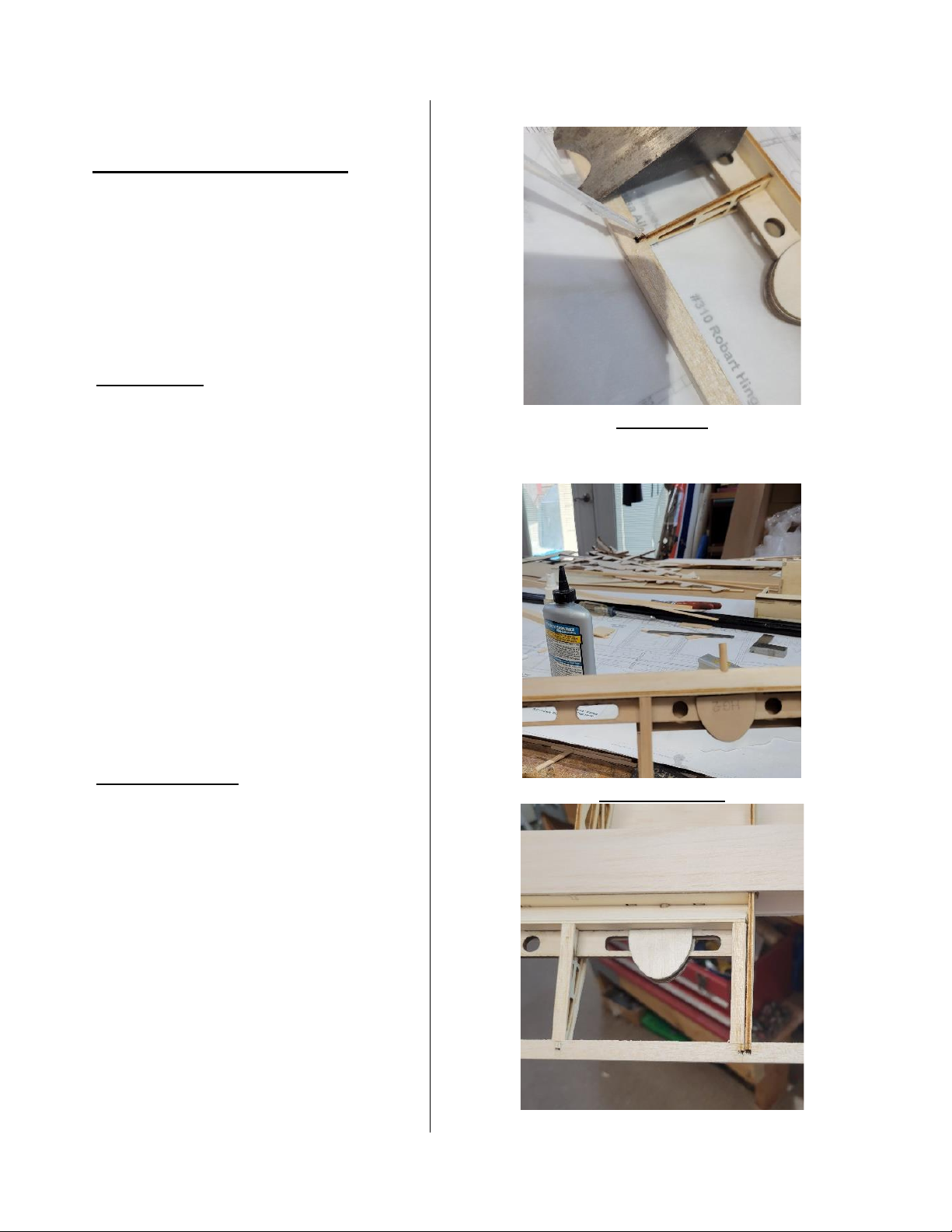
AILERON ASSEMBLY
54. Locate all aileron ribs for the wing
you are working on (AR) & (AR-4'S) in
cut sheets #7,8 & 9. Locate aileron L.E.
(A-1's) on cut sheet #5 & the remaining
pre-shaped notched T.E. you cut from
earlier.
55. (PHOTO-36) Locate parts (A-2) on
cut sheet #17. As you had done earlier
with the wing install the 3/32” balsa
hinge covers (HG-2'S) located on cut
sheet #13 over each hinge channel on
top and boom of (A-2) Using
Carpenters glue making sure not to get
any glue in hinge channel. Refer to wing
plans if needed.
56. Once this is dry aach to (A-1)
snapping into notches then once
sased with t glue these together
with Thick CA.
57. (PHOTO SET-37) With this aileron
L.E. assembly done start inserng (AR)
aileron ribs into the correct locaon
referring to the plans. (NOTE: The two
(AR-4) ribs with (S-N-L) tabs go in slots
lining up with aileron bay on wing). All
ribs have the (S-N-L) to lock over the
back side of (A-1) Ply aileron L.E. With
ribs in place held down over plans
covered with Parchment Paper install
the pre-shaped notched trailing edge
stock to back of the ribs. Locate the
(AHM-1 & AHM-2) ply plates in cut
sheet #27 glue (AHM-2) to the boom
PHOTO-36
PHOTO SET-37
Page 26
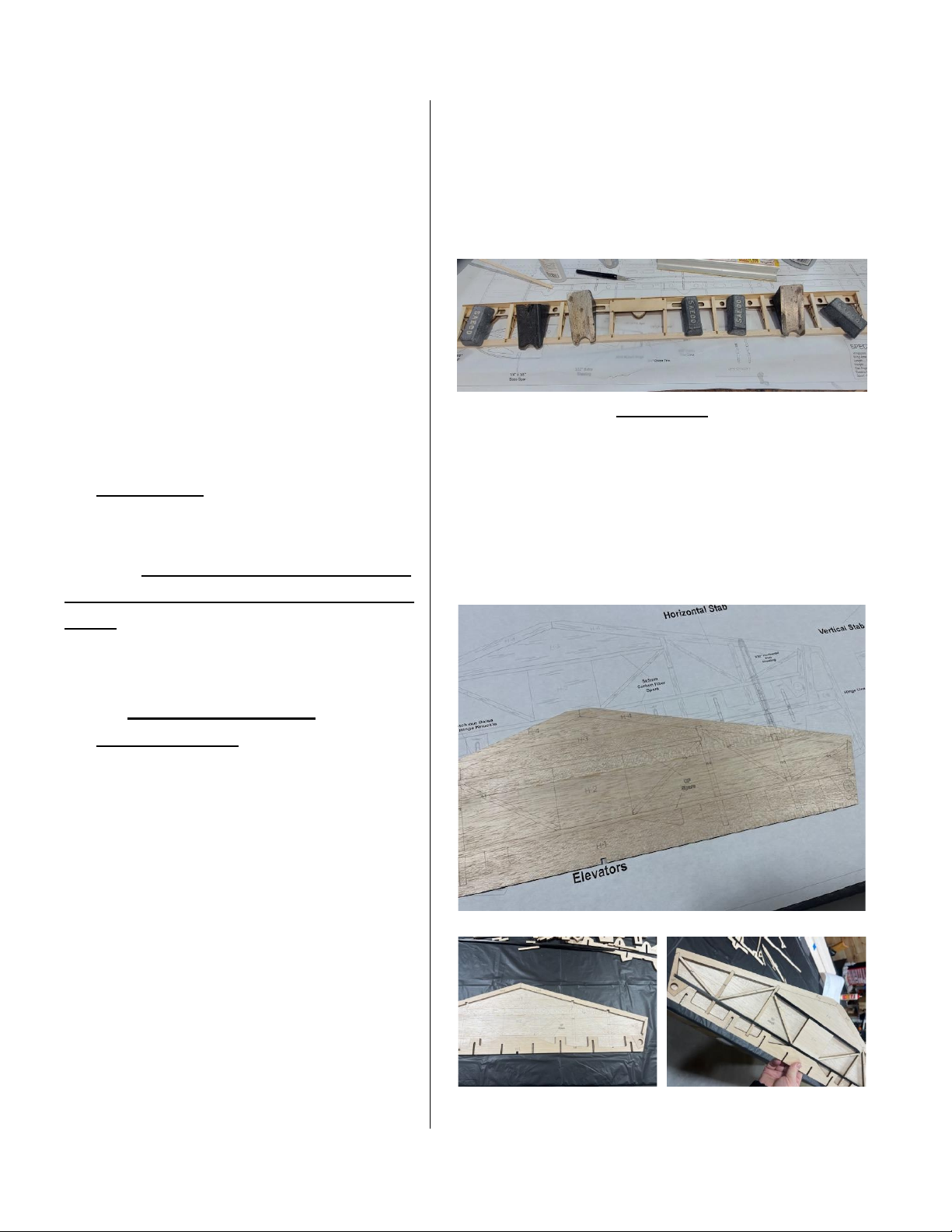
26
of (AHM-1) using lasered outline as
guide. Snap this assembly into place
over the two aileron bay ribs that have
the (S-N-L) tabs on boom of them with
(AHM-2) facing down. Install the balsa
1/4” Tri. stock. Glue all in place using
Thick CA or Epoxy.
58. Once all is dry, remove & glue the
3/4” balsa triangle hinge stock in place
using Carpenters glue. Use 3/16”
dowels to get laser cut holes lined up
with the holes in (A-1) let dry.
59. (PHOTO-38) Once the aileron has
dried, lying at and weighted down you
can sand to match wing in all areas
needed. Repeat the same steps for the
opposite wing before going to the next
steps. (NOTE: Again, make sure to build
right and le-hand parts.)
TAIL FEATHERS
60. (PHOTO SET-39) Locate (H-1), (H-2)
through (H-10) on cut sheet #14.
Carefully remove all these parts from
the cut sheet. Lay at the horizontal
stab sheet that has lasered parts lines
drawn out with lines facing up. Install
(H-1) onto the boom edge of this
sheet keeping it as ush and even with
back edge of sheet then glue using Thin
CA. Lightly rough up the CF spars before
glueing. Lay all other parts into correct
locaons including the two CF square
spars locking them into the ght
notches in adjacent piece ll all pieces
are installed without glue. Once happy
PHOTO-38
PHOTO SET-39
Page 27
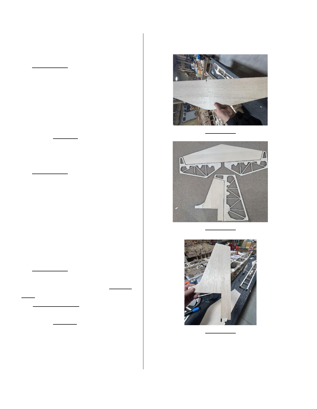
27
with t start gluing all parts while locked
in place with Thin CA.
61. (PHOTO-40) Once all of this is dried
lightly sand unsheathed side ll happy &
removing dust. Next locate the other
pre-cut sheeng for stabilizer and install
it using Thick CA on all cross members
and outer frame or use carpenter's glue.
Weight down ll dried thoroughly.
62. Locate Elevator parts (E-1's) on cut
sheet #11, (E-1A's) on cut sheet #13 and
parts (E-2) to (E-8) on cut sheet #15.
63. (PHOTO-41) Laminate parts (E-1)
with two (E-1A's) then using plans build
both elevators using all the remaining
parts gluing using thin & thick CA. Once
built install the ply (EHM) located in cut
sheet #7 horn mounts into the open
cutout on the top and boom of both
elevators in (E-1A's). Install the 1/4”
balsa triangle stock on the front of
elevators in between hinge holes only.
64. (PHOTO-42) Locate all the parts for
the vercal stabilizer (V-1), to (V-9) on
cut sheets #14. Assemble the Vercal
Stab in same manner as you did with
the Horizontal Stab assembly.
65. Locate Rudder parts (R-1) & (R-1A's)
on cut sheets #12 & 13. Laminate these
three parts the same way you did
elevator parts. Locate remaining parts
(R-2) to (R-11) on cut sheet #15.
PHOTO-40
PHOTO-41
PHOTO-42
Page 28
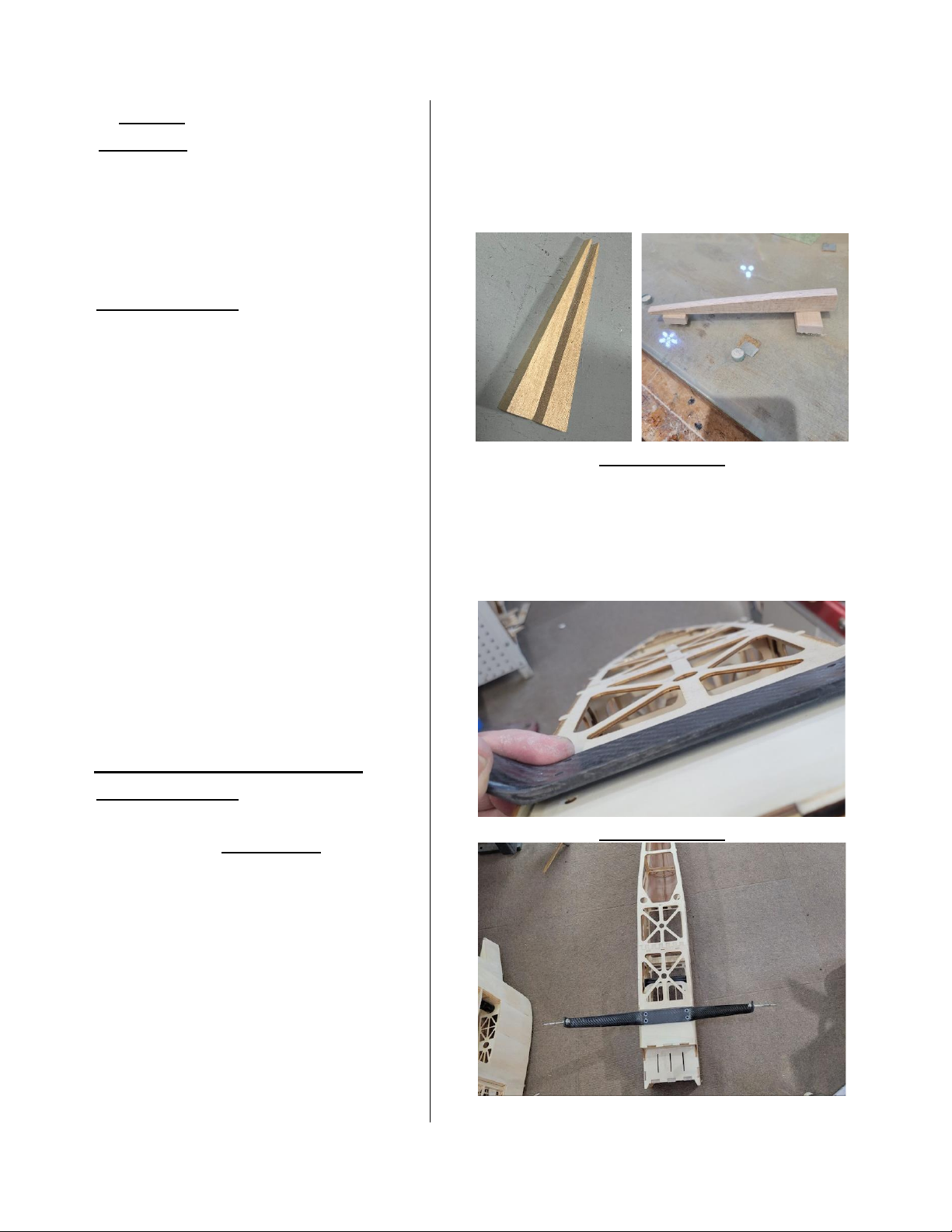
28
Build Rudder over plans as you did with
the Elevators. Once built install the two
ply (RHM) rudder horn mounts from cut
sheet #7. Install the 1/4” triangle balsa
stock on the front hinge side of the
rudder in between hinge holes only.
66. (PHOTO SET-43) Once tail feathers
are built, locate the roughly shaped tail
blocks supplied. Using some scrap 3/8”
balsa sheet make a T-Shape simulang a
false horizontal and vercal stab. Tack
glue the tail blocks to this assembly.
Very lightly tack glue this assembly
centered on top rear of fuselage where
horizontal and rudder will be. Glue the
supplied tail blocks against (F-6) Thick
CA making sure not to glue to false stab
assembly. When in place start sanding
enre assembly to correct shape as
seen on plans and photos. Remove false
stab. & vercal from the tail block
assembly.
MAIN GEAR INSTALL.
67. (PHOTO SET-44) Using the (4) 8-32 x
.75” Cap Screws & washers located in
parts bag labeled Main Gear, install
main gear onto the (GM) main gear
plate with T-Nuts that were added to
the inside gear plate during fuel tank
compartment construcon.
68. Locate & install tall wheel assembly
using provided hardware included Use
plans as reference to these.
(NOTE: These assemblies can be
removed before covering & reinstalled.
PHOTO SET-43
PHOTO SET-44
Page 29
29
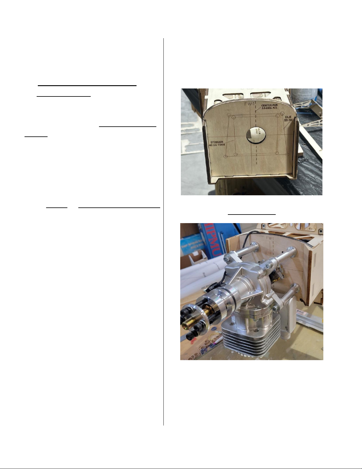
MOUNTING ENGINE
69. (PHOTO SET-45) The rewall is pre
marked for centerline the (Dash Line) to
the right is oset center to mount
engine for the built in 2.5 degrees right
thrust. This will be the centerline of
your engine. Carefully locate where
engine mounng holes should be, using
the dashed line on the rewall & the
solid horizontal line. Drill out
appropriately sized holes for your
engine using these lines as guides,
install T-nuts or Washers with Lock Nuts
on the inside of rewall & mount your
engine per manufacturers
recommendaons. (NOTE: Firewall is
marked for the DLE 55-RA & Snger 40CC Twin.
PHOTO SET-45
Shown is DLE 55CC-RA Installed!
Page 30
30
COWL MOUNTING
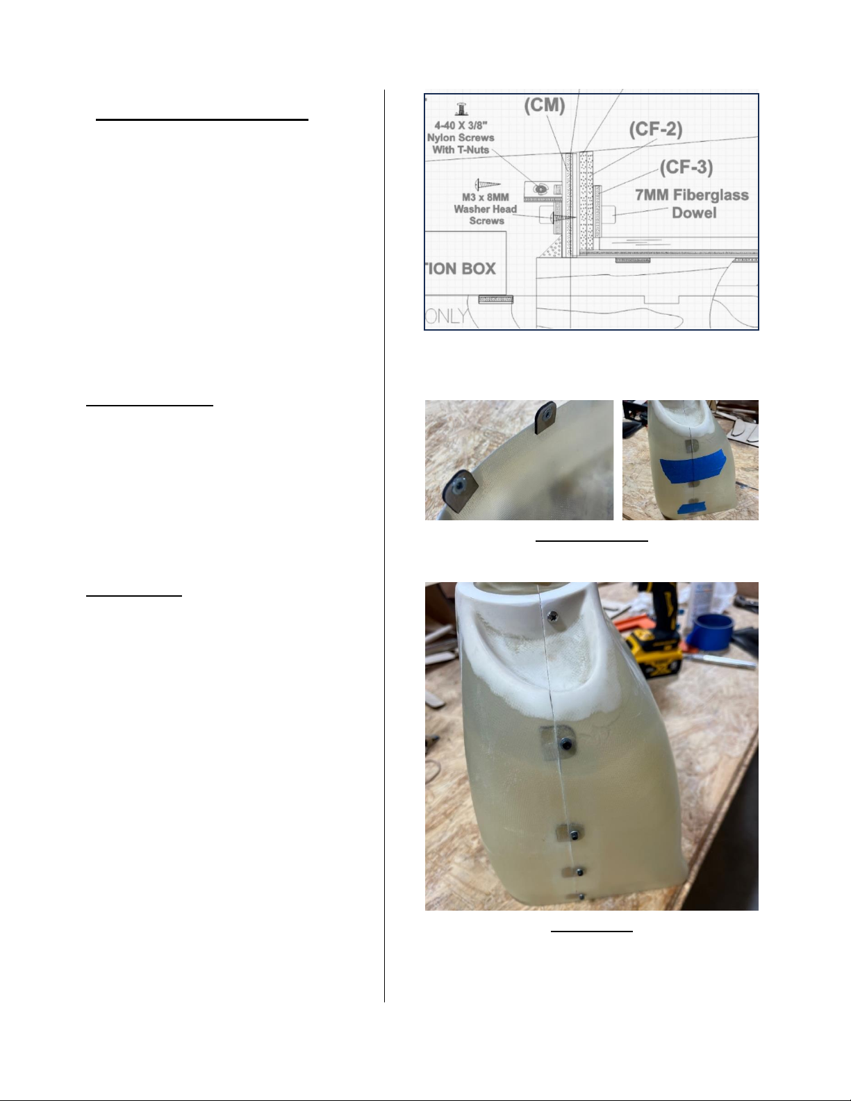
70. Located in cut sheet #6 nd parts
(CMB-1, CMB-2 & CMB-3'S) assembly
one set for top of cowl mounng. Refer
Fuselage plans for detail. Once these
are assembled glue onto the cowl side
of (CM) using lasered lines as guide &
install a anged head screw into each
one as well as gluing in place. See
drawing from Fuselage plans for detail
to the right > > >
71. (PHOTO SET-46) Locate (CM) in cut
sheet #6 and glue in place directly over
(F-1) on front top of fuselage. Keep 90
degrees vercal and install a piece of
3/8” balsa stock in front of this former.
See Fuselage plans for reference.
72. (PHOTO-47) Locate the (CS-1 & CS-
2) cowl screw tabs in cut sheet #7.
Rough up the top inside lip of the
boom cowl piece with sandpaper then
clean with alcohol. Using epoxy
sparingly glue these tabs onto the inside
using the laser engraved line on the tab
as a guide to how far up to locate from
cowl edge.
73. Once the cowl tabs are dry, stand
both top and boom cowl pieces on the
rewall end & tape ghtly together.
74. Using appropriate size drill bit 3/32”,
drill holes into the top secon of the
cowl into the wood tabs. (Make sure
you’re staying about 3/16” away from
the seam). Once holes are drilled, install
(Cowl mounng tongue detail from plans as
reference).
PHOTO SET-46
PHOTO-47
Page 31
31
M3 T-Nuts located in parts bag labeled
(COWL) to inside of all tabs. Squeeze T-
Nuts into the tab with pliers gently to
set them. Repeat this for other side of
cowl.
75. Insert the Nylon screws into holes
and ghten down to check the t of the
top and boom cowl pieces.
76. Disassemble cowl halves. With the
plane lying upside down hold the cowl
boom in correct posion to engine and
muer and mark carefully where to cut
out cowl for clearance. (NOTE: It’s best
to cut less then re-t then remove more
ll happy in this procedure).
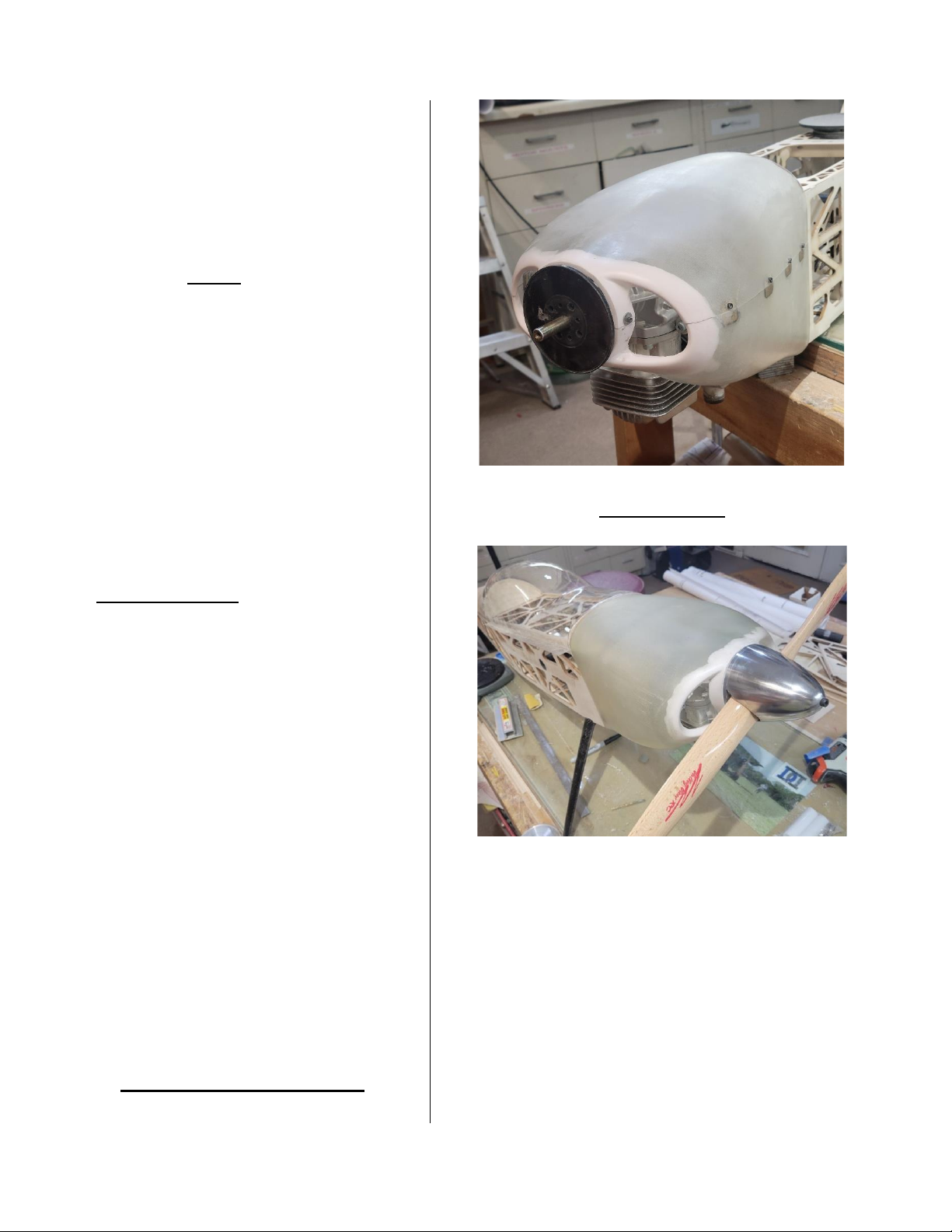
77. (PHOTO SET-48) Before ng cowl
to fuselage mount spinner onto engine
for reference. Install boom cowl
secon.
78. Install top cowl piece on cowl
boom using the screws used earlier.
Once these are screwed together, move
the cowl back and forth unl you are
happy with alignment at the spinner.
(3/32” gap is ideal).
79. Once happy with the alignment,
tape cowl to spinner and fuselage to
hold while drilling. Drill holes through
cowl at each tongue mount locaon
then remove cowl and install T-Nuts to
the inside of all cowl mounng tongues.
COCKPIT - CANOPY
PHOTO SET-48
Page 32
32
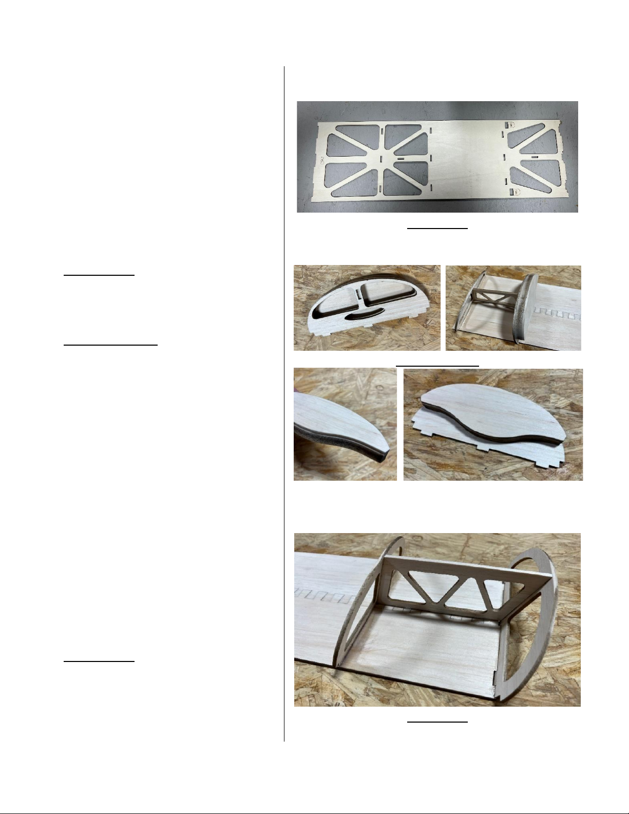
80. With the plane sing upright on a
work bench and cowl fully installed, you
can now get an accurate canopy frame
built & canopy cut properly.
81. Locate parts for canopy frame &
cockpit (CP-1) in cut sheet #26 locate
(CP-2 TO CP-12) in cut sheets #19 & 20.
Parts (CF-1, CF-2 & CR) in cut sheets #19
& 20.
82. (PHOTO-49) Start by installing the
3/16 square balsa stringers from front
to back even with outer edges of (CP-1).
83. (PHOTO SET-50) Laminate (CF-1) &
(CF-2) together. Then nd (CF-3) in cut
sheet #27. Glue this onto the inside of
(CF-2) as a doubler for dowl. Glue this
assembly into front notches on (CP-1)
assembly while keeping them 90
degrees vercal.
84. Snap (CP-2) & (CP-3) in place into
proper notches on top of (CP-1).
Laminate (CP-4), (CP-5) & (CP-6) then
snap onto front of (CP-3) & into (CP-1)
as seen in images. Using Thick CA glue
these parts to (CP-1) cockpit frame.
85. Laminate parts (CP-7), (CP-8), & (CP-
9) as seen on fuselage plans. See photos
for reference.
86. (PHOTO-51) Snap (CP-10), (CP-11),
& (CP-12) in place then glue using Thick
CA. Glue laminated seat assembly to the
front side of this assembly as shown on
fuselage plans.
PHOTO-49
PHOTO SET-50
PHOTO-51
Page 33
33
87. (PHOTO SET-52) Install the two sets
of the canopy mount bracket (CMB-1) &
(CMB-2) in cut sheet #6. Glue these
together to form canopy mounng
bracket. Install through slot on (CF-1)
before sheeng the back of cockpit
frame.
88. (PHOTO SET-53) Sheet the front and
back of cockpit frame with the supplied
1/32” plywood sheets (CPS-1 & CPS-2).
89. With canopy frame sing in place,
install canopy rear (CR) to the backside
of (CP-12). Install the 7-mm x 1”
berglass dowel that goes into (CF-1), &
(CF-2) glue in place using Thick CA. See
drawing from fuselage plans to right >>
90. (PHOTO-54) Locate ply mounng
plates labeled “LATCH” in cut sheet #5.
Glue these to the laser marked locaon
on the upper inside of each fuselage
doubler side. Using the small 1.5M X
6MM screws install the canopy latches
with pin facing to back onto each of
these plates. Sit canopy frame onto
fuselage and using the small ply
alignment ring (CMB-3) glue this to
canopy mount with latch pin inside for
alignment. This ring gives you the
ghtest t for canopy. Use see Fuselage
plans detail for canopy mount to right >
90. (PHOTO-55) With canopy frame all
locked down in place. Sand cockpit
PHOTO SET-52
PHOTO -53
(Canopy dowel detail from plans for reference)
(Canopy latch detail) PHOTO-54
Page 34
34
frame to accept bubble canopy easily.
(Note: Part (CR) should be around
3/32” taller than turtledeck for canopy
to overlap properly.) Once the sanding
is done you can paint the inside of the
cockpit the color of your choice. Aer
the paint dries install a pilot gure (NOT
INCLUDED) 4.25” tall maximum &
included instrument panel decal. You
may want to clear coat all of this before
gluing clear canopy in place if desired.
(NOTE: Make sure no dust or wood
shavings are in cockpit before glueing
canopy on).
91. (PHOTO-56) (NOTE: The clear
canopy can be cut out without the
canopy frame on the fuse.) Pre-cut
canopy out of molded frame staying as
close to outside edges as possible. sit
canopy over the back of the cowl & over
the front of the turtle deck. Tape it all
down snug against these areas & sides.
92. Apply masking tape over the seam
where the cowl & canopy meet. Apply
tape on the back of canopy overlapping
turtledeck about ¼”. Also, tape where
the fuselage sides meet the canopy.
93. Remove carefully & cut the canopy
on these tape lines. Once you are happy
with the cuts, sit the canopy onto the
frame & glue using canopy glue.
PHOTO-55
PHOTO-56
Page 35
35
WHEEL PANTS94.
(PHOTO SET-57) Locate the wheel pant
doublers (WPD) in cut sheet #6. Install
two of the T-Nuts as shown. Glue this
assembly in the correct locaon inside
each wheel pant using epoxy keeping
parallel to boom of wheel pant.
(NOTE: Make sure to make a right and
le not two of one side). Also, rough up
the inside where you will glue this in
place with sandpaper. Aer glue has
dried you can carefully drill correct size
holes into the gear side of each pant
corresponding to the T-Nuts and Axle
Hole. (Note: You will also have to notch
out the berglass for axle to slide into
pant from boom see wheel pant
detail from plans to the right.)>>>>
PHOTO SET-57
Page 36
36
Bare Bones ready to cover
Page 37
37
Radio & Servo Images
Control Surface Throws
(Low –Medium-High)
Ailerons: 1.22”, 1.5” & 1.75”
Elevators: 1.75” 3.25” & 4.25”
(EXPO RATES)
Ailerons: 10%, 30% & 50%
Elevators: 0%, 60% & 80%
Rudder: NO Rates @ 35% EXPO
Page 38
38
CENTER of GRAVITY - Set-Up
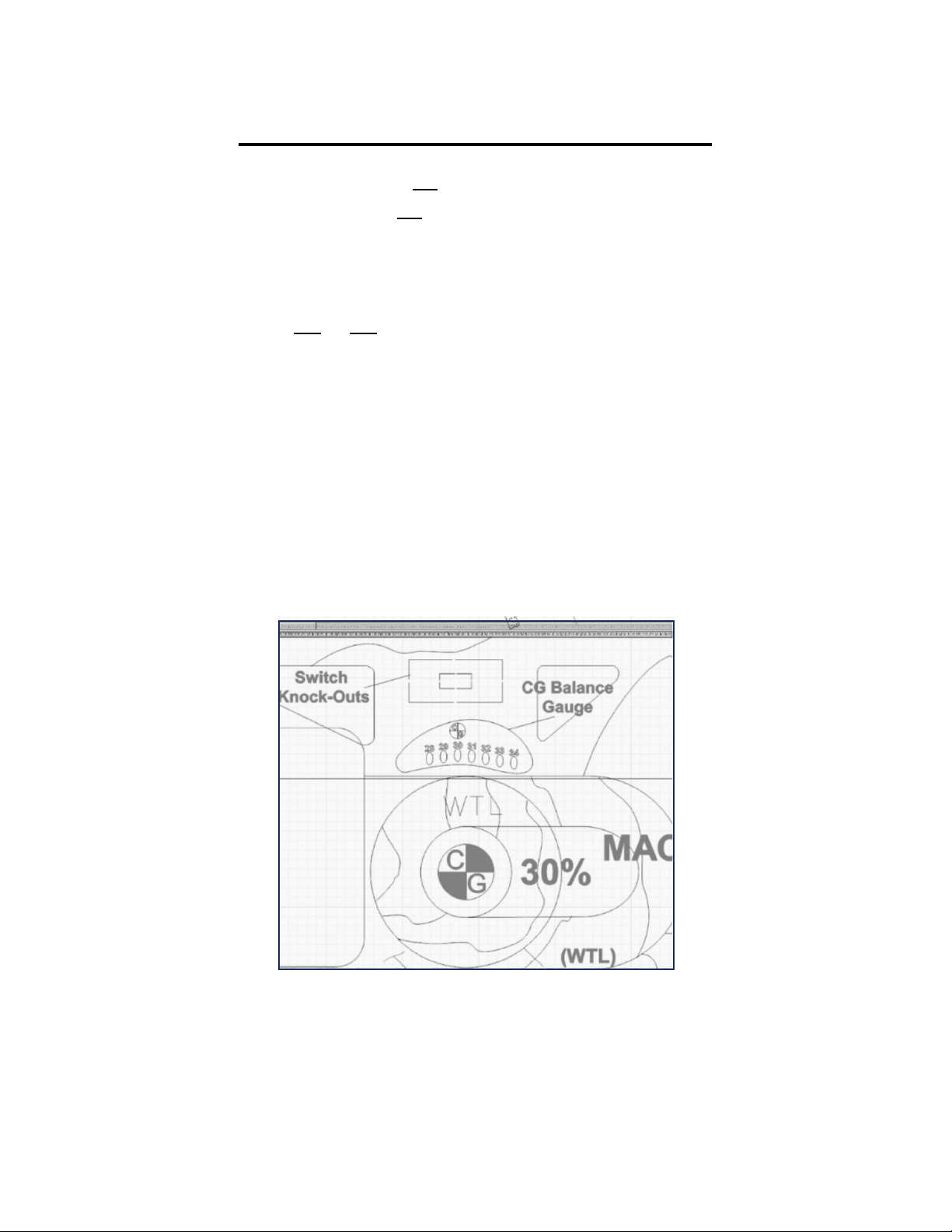
The AeroMax is equipped with a built in CG Gauge on the inside of each fuselage doubler over
wing tube socket. Simply choose what CG seng you want and run a string through the
fuselage sides the holes corresponding to that seng. Tie a loop in the ends and suspend from
a dowel run through the loops. Ensure wings, canopy and everything that will be in the aircra
during ight minus fuel is installed. Use the baery pack to adjust for the balance preferred.
Oponal hatches between F-3 to F-6 may be used for baery placement.
All recommended control surface throws are with a 30% CG or 5” back from leading edge of
wing.
CG Range is 4-5/8” = 28% MAC to 5-1/2” = 34% MAC. These are max and minimum
recommendaons and should be selected based on ying experience and style!
The further forward you make the CG the more nose heavy and therefore tamer the airplane.
Moving the CG a makes controls more sensive so make those changes gradually to avoid a
seriously tail heavy and dangerous situaon. (Note: See drawing from fuselage plans below of
CG Balance Gauge for reference.)
(CG Gauge detail from plans for reference)
Page 39
39
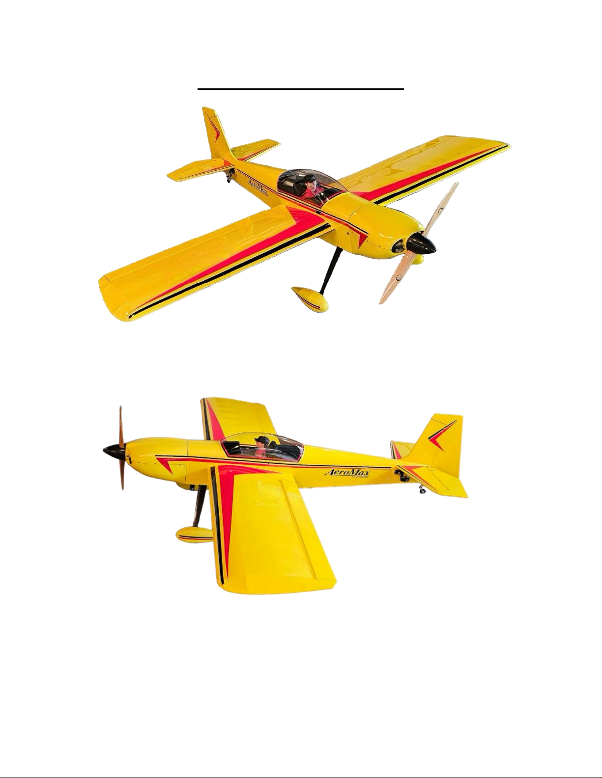
Finished Ready to Fly
We wish you happy and safe ying from RC AirDesigns.
Page 40

40
 Loading...