

Page 1
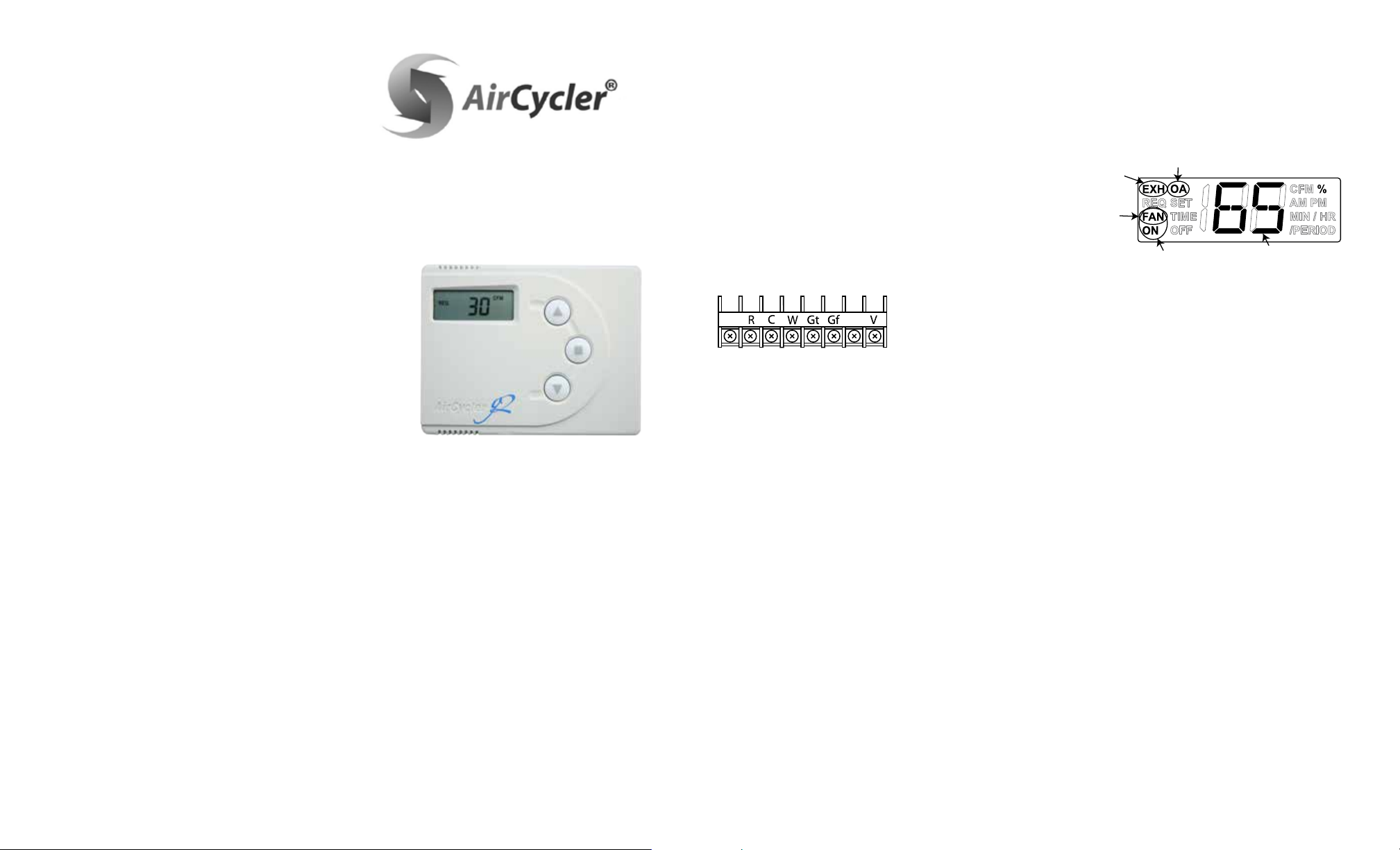
APPENDIX B - Troubleshooting
THE EXHAUST
FAN IS ON
THE THERMOSTAT
HAS TURNED ON
THE CENTRAL FAN
THE AIRCYCLER® G2
HAS FORCED THE FAN
THE DAMPER
IS OPEN
PERCENTAGE OF
VENTILATION COMPLETE
Blank Display on the AirCycler® g2 controller.
Solution Check:
1. Confirm that the furnace has power.
2. Confirm that the thermostat is operational.
3. Confirm that the furnace will call for heat from the
thermostat.
4. Confirm that the fan operates with a fan only signal
from the thermostat
5. Confirm that the furnace is providing 24VAC to the
AirCycler® g2
6. Confirm the wiring conforms to the wiring diagram.
7. Make sure the cover is firmly seated on the base.
The AirCycler® g2 turns the furnace fan on and o, but
the motorized damper does not cycle.
Solution Check:
1. Confirm that the AirCycler® g2 is providing a 24VAC
signal to the motorized damper.
2. Confirm the 24 VAC motorized damper is operational
by powering directly with a 24 VAC signal
3. Verify there is continuity in the wiring between the
damper and the AirCycler® g2
4. Confirm damper power switch is in up or automatic
position
The A/C turns on during fan cycling calls
Solution Check:
1. Verify that the wiring conforms to the wiring diagram.
2. Confirm that the G wire is properly connected.
Note: The G wire must be interrupted by the AirCycler®
g2. Do not run the G wire in parallel.
The EXH icon is ashing.
This indicates the g2 controller has seen the
FanConnect™
exhaust fan on for more than 4 hours.
Solution Check:
1. Turn o exhaust fan.
2. Check wiring from FanConnect™ switch to g2
controller.
For more troubleshooting and frequently asked questions,
visit: www.aircycler.com/pages/troubleshooting
For Limited Warranty information please visit:
www.aircycler.com/products
Technical Support:
1.877.FAN.CONTrol
(1.877.326.2668)
AIRCYCLER®
411 PLAIN STREET
MARSHFIELD, MA 02050
WWW.AIRCYCLER.COM
Ventilation Products
AirCycler® g2
INSTALLATION & USER’S MANUAL
VENTILATION MADE BREEZY!™
A BREEZE TO INSTALL • A BREEZE TO USE!
This product may be protected by one or more of the
following patents and patents pending: 8185244,
7258280, 6431268, 881806, 547017, Canada 2245135
INTRODUCTION
In the past, homes depended on natural leaks for ventilation.
Today, energy efficient homes are built to reduce natural
ventilation and leaks. Inadequate ventilation can increase
indoor air pollutants to harmful levels. Indoor air quality
is typically 5 to 10 times more polluted than outside air.
Controlled ventilation provides adequate air flow to the
home without compromising its efficiency.
SAFETY CONSIDERATIONS
Read and follow manufacturer’s instructions carefully.
Follow all local electrical codes during installation. All
wiring must conform to local and national electrical codes.
Improper wiring or installation may result in personal injury
or product and property damage.
INSTALLATION CONSIDERATIONS
The AirCycler® g2 requires 24VAC (R and C terminals) to
be connected for proper operation. The controller will not
operate without these two connections.
Vnc - Normal Closed Vent
R - 24VAC Power
W - Heating
Vnc Ex
Gt - Fan From Thermostat
Gf - Fan to Furnace
C - Common
V - Vent
Ex - Exhaust Fan
The wires (R, C, & W ) from the air handler to the thermostat
can run parallel with the wiring from the AirCycler® g2 to
the air handler. The fan wire (G) must be interrupted by the
AirCycler® g2. Some thermostats do not require a common
(C) connection. The AirCycler® g2 requires this for power,
which must be wired to the furnace.
DAMPER LOCATION
The fresh air damper can be located anywhere in the inlet
duct. Minimize the length of the inlet duct to improve air
flow and improve system efficiency. It is recommended
that the damper be as close to the return air plenum and
the AirCycler® g2 controller as possible, and the inlet duct
connect to the return plenum upstream of the system filter,
and down- stream of any duct mounted sensors.
DAMPER INSTALLATION
The damper may be installed in any position. It is
recommended to install it with the motor at the 12 o’clock
position if mounted horizontally. Air may flow through in
either direction, although it is recommended to install with
the crimped end as the outlet. Use care to avoid distorting
the damper housing and provide adequate support. Upon
system start up be sure to set damper power switch to
UP or AUTOMATIC position.
CHOOSE A FRESH AIR LOCATION
ASHRAE recommends that the fresh air intake be located
at least 10 ft. from any source of pollutants, such as auto
exhaust, dryer exhaust, exhaust from any fuel-burning
appliances, etc. Avoid installation near odor sources such as
garbage bins or barbecue grills. A minimum of 3 ft. above
ground is recommended to avoiding ingress of leaf litter,
grass clippings, etc. Do not use a crawl space, basement, or
attic as a source of intake air. Always be sure to comply with
local building codes and requirements regarding fresh air
inlets.
BATTERY (MODEL CR1220)
The AirCycler® g2 is equipped with a real time battery
backed-up clock for use with the Operation Hours
setting ONLY. If not setting the hours of operation, the
included battery is not required. All other settings are
saved in nonvolatile memory.
NORMAL OPERATION DISPLAY
• When the AirCycler® g2 is in Normal Operation,
the display will show the percentage of ventilation
complete for the current hour.
• If the central fan is on, the FAN and ON icon will be
illuminated.
• If the exhaust (bath) fan is on, the EXH icon will be
illuminated.
• If the outside fresh air damper is open, the OA icon will
be illuminated.
• If the exhaust fan is running its delay time after
bathroom occupancy, the delay time countdown, MIN
and EXH icons will be illuminated.
• If the thermostat is calling for heat or cool, the FAN
icon will be illuminated without the ON icon.
• The ON icon is only illuminated when the AirCycler® g2
has forced the central fan on. (Calculated Time Mode
Only)
• Press the MODE key at any time during normal
operation to set the current time of the day.
• If the EXH icon is blinking, it indicates the exhaust fan
has been on for more than 4 hours or the connection
to the AirCycler® g2 controller was lost.
Page 2
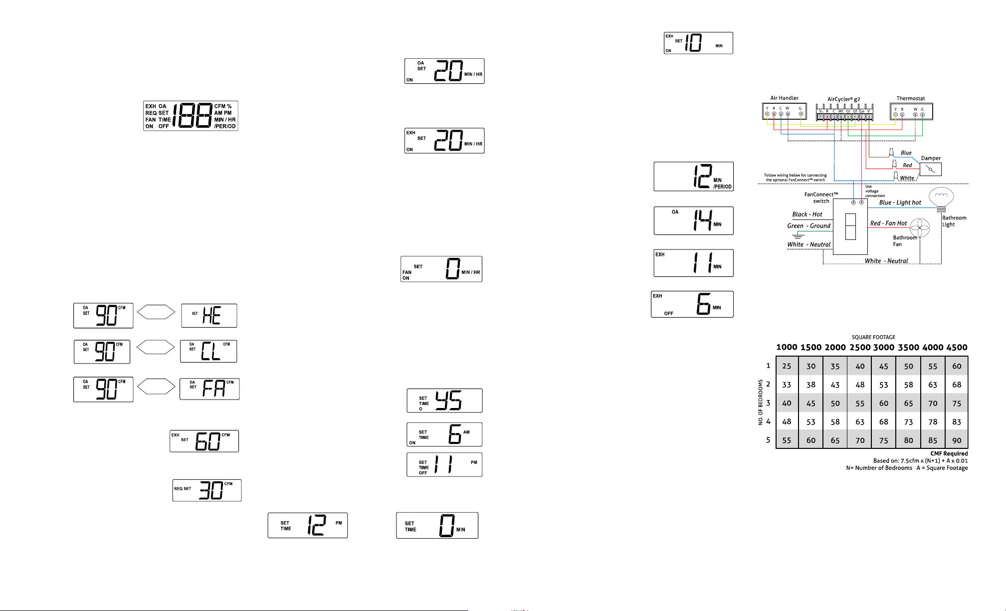
1.0 INSTALLATION INSTRUCTIONS
ALTERNATING
DISPLAY
1.1 CONTROLLER LOCATION
The AirCycler® g2 controller can be installed near the
thermostat or out of view on/near the air handler unit.
Warning: Before installing the AirCycler®, turn off all power to the furnace. There may be more
than one power to disconnect. Electrical shock can cause injury or death.
1.2 INSTALLATION
On power up, all icons will be
illuminated for 3 seconds.
There are two setup methods:
Calculated Time and Calculated Flow. Calculated Flow is
used primarily with the optional FanConnect™ bath fan/
light switch.
To set up the AirCycler® g2 based on Calculated Flow, press
the UP arrow within 3 seconds of power up. To setup based
on Calculated Time, press the DOWN arrow within 3 seconds
of power up and skip to section 3.0.
Pressing center MODE button always advances to the next setting.
2.0 CALCULATED FLOW SET UP
2.1 SETTING MEASURED SUPPLY AIR FLOW
The measured flow is the amount of air that enters the
return side of the air handler from the outside air vent. Enter
the measured flow. To accommodate variable speed air
handlers, you can enter different values for heat, cool and
fan. Factory default is 90 CFM.
Flow measured
during heat call
Flow measured
during cooling call
Flow measured
during fan only
call
2.2 SETTING MEASURED EXHAUST AIR FLOW*
Enter the measured flow from the
exhaust fan. Factory default is 60 CFM.
*Only if FanConnect™ is connected
2.3 SETTING CODE REQUIRED CONSTANT AIR FLOW
Set the required continuous air flow
in CFM based on relevant codes. For
ASHRAE 62.2 see Appendix A. Factory
default is 30 CFM. The AirCycler® g2 will
calculate run times based on settings 2.1
and 2.2.
Press MODE to save all settings and return to normal operation.
CALCULATED FLOW SETUP IS COMPLETE
Continue pressing MODE for Optional Mixing Time, Operation Hours,
and Exhaust Fan Delay Time Settings. See Sections 3.3-3.6 for details.
ALTERNATING
DISPLAY
PRESS MODE
ALTERNATING
DISPLAY
PRESS MODE
PRESS MODE
3.0 CALCULATED TIME SETUP
3.1 SET MINUTES/HOUR OF SUPPLY AIR REQUIRED
Enter the minutes per hour that
you require fresh air to be brought
into the home. Factory default is 20
minutes.
For installations without the FanConnect™ switch, continue
to section 3.3.
3.2 SET MINUTES OF EXHAUST FAN REQUIRED
Enter the desired minutes per hour
you want the exhaust fan to run.
Factory default is 20 minutes per
hour.
If the FanConnect switch is not detected, make sure it is in
the OFF position.
SLAVE MODE
Press the DOWN arrow until the countdown reaches 0.
Press again to get to SL. (SL= slave mode) In slave mode the
exhaust fan runs anytime the central fan is running with the
fresh air damper open. Slave mode will provide a “balanced”
mode of operation.
3.3 SETTING THE OPTIONAL MIXING TIME
If the user needs more central fan
time for whole house mixing than
the amount that is provided by
ventilation time, the central fan can
be configured to run an additional
time period to complete the mixing period. Factory default
is 0 or OFF.
The fresh air damper will not be open during this extra time.
3.4 SETTING OPERATION HOURS
If the user does not want the ventilation system to run
constantly, you can set ON time and OFF time. Factory
default is OFF. If you are not setting an ON and OFF time,
continue to section 3.6.
If you enter YES, the AirCycler® g2 will prompt you to
enter the hour you would like the
ventilation to begin and the hour
you want it to end followed by the
current time.
Set the hour you want the ventilation
to START.
Set the hour you want the
ventilation to STOP.
3.5 SETTING CURRENT TIME
Enter the current time.
Hour Minutes
Followed
by
3.6 EXHAUST FAN DELAY TIME (If using optional
FanConnect™ switch)
Set the desired length of time you would like the bath fan
N
to run after the FanConnect™ has
been turned off. Factory default is 10
minutes.
Press MODE to save all settings and return to normal operation.
CALCULATED TIME SETUP IS COMPLETE
4.0 NORMAL OPERATION DISPLAY STATUS & SETTINGS
4.1 CURRENT STATUS
To get detailed status information, press the UP arrow. The
status displays are the same for both Calculated Flow and
Calculated Time modes.
4.1.1 MINUTES LEFT
The first display is the number of
minutes left in the period (hour).
Pressing the UP arrow again gets
you to the next status screen
4.1.2 OUTSIDE AIR TIME ELAPSED
This display shows the number of
minutes this period that the outside
air damper has been open with the
central fan running.
4.1.3 EXHAUST RUN TIME*
This display shows the elapsed run
time of the exhaust fan for this time
period.
4.1.4 EXHAUST DELAY TIME*
This display shows the exhaust
delay time set.
4.2 CURRENT SETTINGS
Pressing the DOWN arrow during normal operation, scrolls
through the current setting entered by the installer.
For Calculated Flow mode
the screens will show:
Required CFM set
measured outside air CFM
measured exhaust air CFM*
exhaust fan delay time*
If operating time is enabled:
Operating Time On
Operating Time O
* If optional FanConnect™ switch is installed
4.3 SET CURRENT TIME
By pressing the MODE key you will cycle through current
time of day and will be able to change it if needed.
See section 3.5.
4.4 RECORD ALL SETTINGS ON THE INSTALL STICKER
PROVIDED. LIMITED WARRANTY WILL BE VOID IF THE
STICKER IS NOT PRESENT.
5.0 RESET TO DEFAULT VALUES
On initial power up when all icons are lit, hold the UP arrow
for 10 seconds to be prompted to reset all settings to default.
For Calculated Time mode
the screens will show:
Exhaust run time set*
Outside air time in minutes
Exhaust fan delay time*
If operating time is enabled:
Operating Time On
Operating Time O
WIRING DIAGRAM
Use the following diagram to wire your AirCycler® g2.
The controller will not operate correctly if it is not wired
according to the manufacturer’s diagram.
APPENDIX A - ASHRAE 62.2 Reference Chart
For more information about ASHRAE requirements, visit
www.ashrae.org
Rev 92015
 Loading...