

Air Con ACZEM4H4R18, ACZEM4C4R24, ACZEM4C4R18, ACZEM4H4R24, ACZCI4C4R18 Service Manual
...
Service Manual
Model: ACZEM4C4R18/ACZCI4C4R18
ACZEM4H4R18/ACZCI4H4R18
ACZEM4C4R24/ACZCI4C4R24
ACZEM4H4R24/ACZCI4H4R24
(Refrigerant:R410A)

Table of Contents
Service Manual
Part
1. Summary
2. Specications
2.1 Specication Sheet .............................................................................................................2
2.2 Operation Characteristic Curve .......................................................................................... 6
2.3 Capacity Variation Ratio According to Temperature ........................................................... 6
2.4 Cooling and Heating Data Sheet in Rated Frequency .......................................................7
2.5 Noise Curve ........................................................................................................................7
: Technical Information
Ⅰ
........................................................................................................................ 1
............................................................................................................ 2
3. Outline Dimension Diagram
3.1 Indoor Unit .......................................................................................................................... 8
3.2 Outdoor Unit ....................................................................................................................... 9
4. Refrigerant System Diagram
5. Electrical Part
5.1 Wiring Diagram ..................................................................................................................11
5.2 PCB Printed Diagram ....................................................................................................... 14
............................................................................................................11
......................................................................... 1
.......................................................................... 8
...................................................................... 10
6. Function and Control
6.1 Remote Controller Introduction ........................................................................................17
6.2 Brief Description of Modes and Functions ........................................................................20
Part
: Installation and Maintenance
Ⅱ
7. Notes for Installation and Maintenance
8. Installation
8.1 Installation Dimension Diagram ........................................................................................ 29
8.2 Installation Parts-checking ..............................................................................................31
8.3 Selection of Installation Location ...................................................................................... 31
8.4 Electric Connection Requirement .................................................................................... 31
8.5 Installation of Indoor Unit .................................................................................................. 31
8.6 Installation of Outdoor Unit ............................................................................................... 34
8.7 Vacuum Pumping and Leak Detection ............................................................................. 35
8.8 Check after Installation and Test Operation ..................................................................... 35
.................................................................................................................. 29
........................................................................................ 17
................................................... 27
............................................ 27
Table of Contents

Service Manual
9. Maintenance
9.1 Malfunction Analysis ............................................................................................................36
9.2 Flashing LED of Indoor/Outdoor Unit and Primary Judgement ...........................................40
9.3 How to Check Simply the Main Part ....................................................................................45
10. Exploded Views and Parts List
10.1 Indoor Unit .........................................................................................................................61
10.2 Outdoor Unit ......................................................................................................................65
11. Removal Procedure
11.1 Removal Procedure of Indoor Unit ....................................................................................73
11.2 Removal Procedure of Outdoor Unit .................................................................................83
Appendix:
Appendix 1: Reference Sheet of Celsius and Fahrenheit .........................................................95
Appendix 2: Conguration of Connection Pipe ..........................................................................95
Appendix 3: Pipe Expanding Method ........................................................................................96
.............................................................................................................................95
.................................................................................................................36
................................................................61
............................................................................................73
Appendix 4: List of Resistance for Temperature Sensor ...........................................................97
Service Manual
Part
Ⅰ
: Technical Information
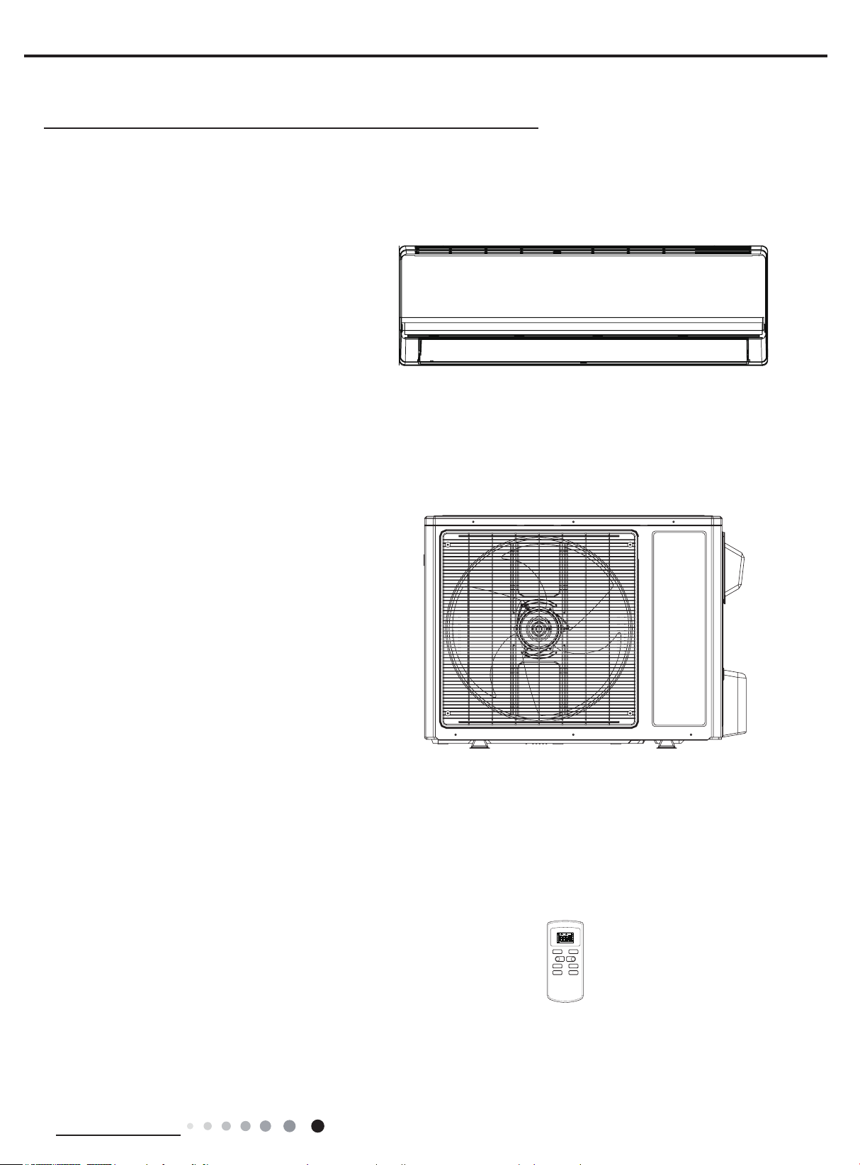
1. Summary
Indoor Unit:
ACZEM4C4R18
ACZEM4H4R18
ACZEM4C4R24
ACZEM4H4R24
Outdoor Unit:
ACZCI4C4R18
ACZCI4H4R18
ACZCI4C4R24
ACZCI4H4R24
Remote Controller:
YX1FF
T-ONT-OFF
AUTO
COOL
DRY
FAN
HEAT
ON/OFF MODE
-
FAN SWING
SLEEP TIMER
SWING
SLEEP
LOCK
SPEED
+
Technical Information
1
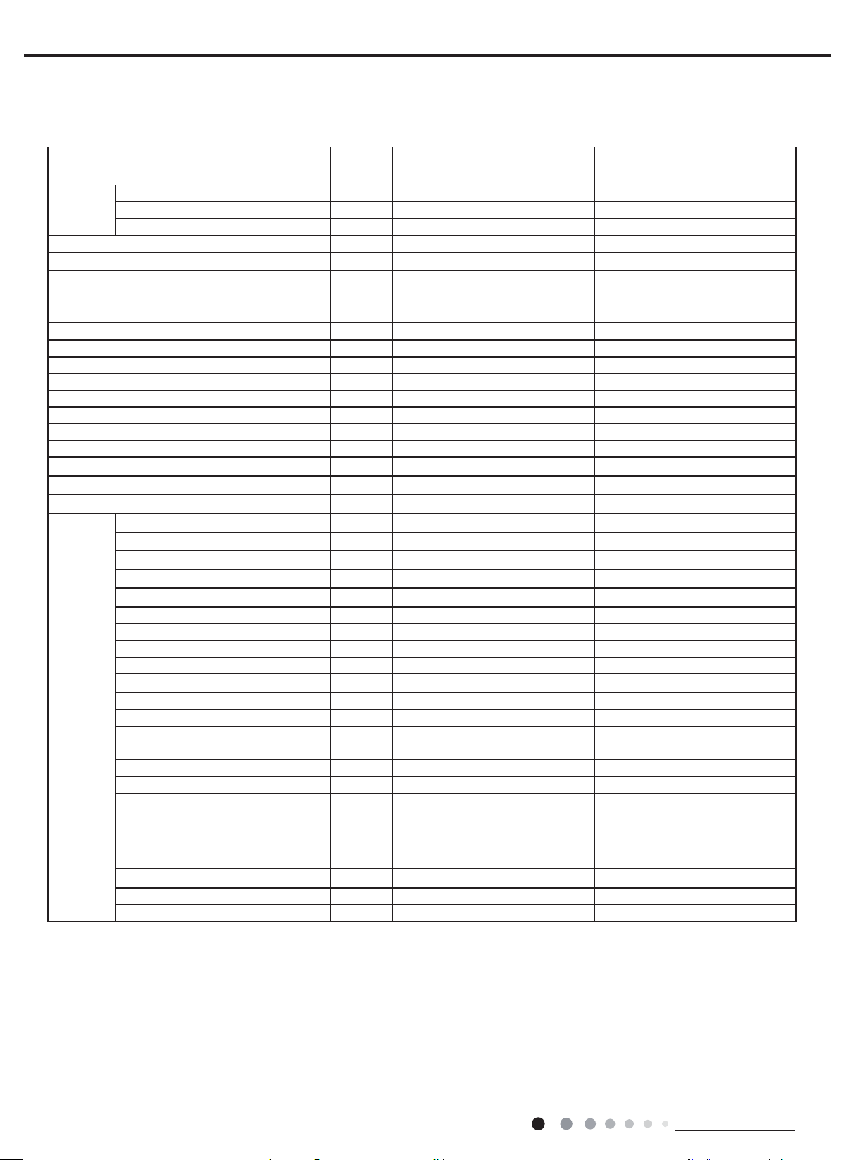
2. Specications
2.1 Specication Sheet
Model ACZEM4C4R18/ACZCI4C4R18 ACZEM4H4R18/ACZCI4H4R18
Product Code CB162008600_L17107 CB162008000_L14385
Power
Supply
Power Supply Mode Outdoor Outdoor
Cooling Capacity(Min~Max) Btu/h 18000(2201~20001) 18000(2201~20001)
Heating Capacity(Min~Max) Btu/h / 19000(3050~23500)
Cooling Power Input(Min
Heating Power Input(Min
Cooling Current Input A 7.98 8.65
Heating Current Input A / 7.52
Rated Input W 2500 2600
Rated Current A 11.09 11.54
Air Flow Volume (S/H/M/L) CFM 860/780/650/550 860/780/650/550
Dehumidifying Volume Pint/h 3.80 3.80
EER (Btu/h)/W 10 8.5
COP (Btu/h)/W / 10.23
SEER 15 15
SCOP / 9
Application Area yd
Indoor Unit
Rated Voltage V
Rated Frequency Hz 60 60
Phases 1 1
Max) W 1800(350~2500) 1950(350~2560)
~
Max) W / 1730(310~2600)
~
Indoor Unit Model ACZEM4C4R18 ACZEM4H4R18
Indoor Unit Product Code CB162N08600_L17107 CB162N08000_L14385
Fan Type Cross-ow Cross-ow
Fan Diameter Length(DXL) inch Ф3 6/7X28 Ф3 6/7X28
Cooling Speed(S/H/M/L) r/min 1500/1200/1050/900 1500/1200/1050/900
Heating Speed(S/H/M/L) r/min / 1500/1250/1150/1050
Fan Motor Power Output W 20 20
Fan Motor RLA A 0.32 0.32
Fan Motor Capacitor μF 1.5 1.5
Evaporator Form W Aluminum Fin-copper Tube Aluminum Fin-copper Tube
Evaporator Pipe Diameter inch Ф2/7 Ф2/7
Evaporator Row-n Gap inch 2-3/50 2-3/50
Evaporator Coil Length (LXDXW) inch 28 1/7X1X12 28 1/7X1X12
Swing Motor Model MP28VB MP28VB
Swing Motor Power Output W 2 2
Fuse Current A 3.15 3.15
Sound Pressure Level (S/H/M/L) dB (A) 48/42/39/36 48/42/39/36
Sound Power Level (S/H/M/L) dB (A) 58/52/49/46 58/52/49/46
Dimension (WXHXD) inch 37X11 2/3X8 37X11 2/3X8
Dimension of Carton Box (LXWXH) inch 39 4/5X15X11 1/5 39 4/5X15X11 1/5
Dimension of Package (LXWXH) inch 39 8/9X15X11 4/5 39 8/9X15X11 4/5
Net Weight lb 26.46 26.46
Gross Weight lb 33.07 33.07
~
2
208/230 208/230
27 1/2-40 2/3 27 1/2-40 2/3
Service Manual
2
Technical Information
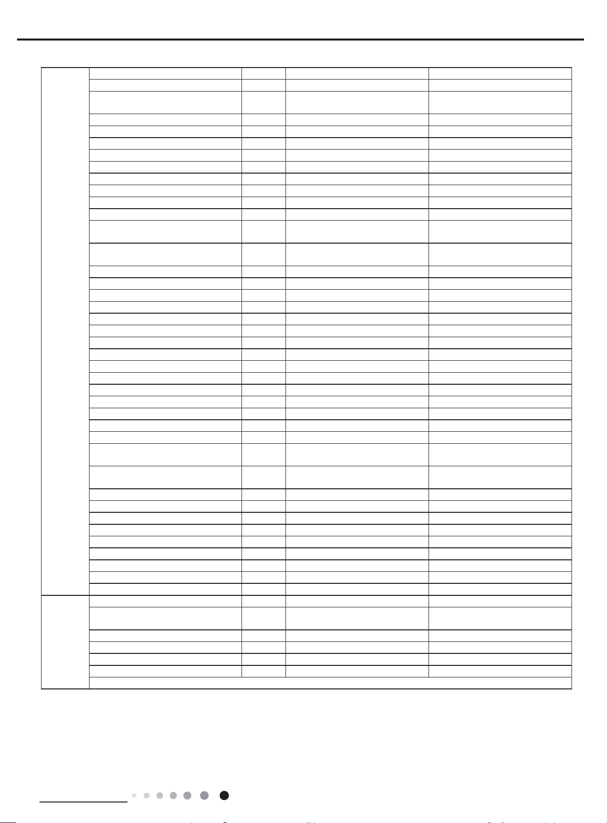
Service Manual
Outdoor
Unit
Connection
Pipe
Outdoor Unit Model ACZCI4C4R18 ACZCI4H4R18
Outdoor Unit Product Code CB145W04100_L17107 CB145W04200_L14385
Compressor Manufacturer
Compressor Model QXA-B141zF030A QXA-B141zF030A
Compressor Oil 68EP 68EP
Compressor Type Rotary Rotary
Compressor LRA. A 25 25
Compressor RLA A 7.2 9.7
Compressor Power Input W 1440 1440
Compressor Overload Protector 1NT11L-6233 1NT11L-6233
Throttling Method Capillary Capillary
Set Temperature Range °F 60.8~86.0 60.8~86.0
Cooling Operation Ambient
Temperature Range
Heating Operation Ambient
Temperature Range
Condenser Form Aluminum Fin-copper Tube Aluminum Fin-copper Tube
Condenser Pipe Diameter inch Ф3/8 Ф3/8
Condenser Rows-n Gap inch 1-3/50 1-3/50
Condenser Coil Length (LXDXW) inch 33 3/5X8/9X26 33 3/5X8/9X26
Fan Motor Speed rpm 450/800 450/800
Fan Motor Power Output W 60 60
Fan Motor RLA A 0.37 0.37
Fan Motor Capacitor μF / /
Outdoor Unit Air Flow Volume CFM 1883 1883
Fan Type Axial-ow Axial-ow
Fan Diameter inch Φ20 1/2 Φ20 1/2
Defrosting Method / Automatic Defrosting
Climate Type T1 T1
Isolation I I
Moisture Protection IP24 IP24
Permissible Excessive Operating
Pressure for the Discharge Side
Permissible Excessive Operating
Pressure for the Suction Side
Sound Pressure Level (H/M/L) dB (A) 56/-/- 56/-/-
Sound Power Level (H/M/L) dB (A) 66/-/- 66/-/-
Dimension (WXHXD) inch 37 3/5X27 3/5X15 3/5 37 3/5X27 3/5X15 3/5
Dimension of Carton Box (LXWXH) inch 40 2/5X17 8/9X28 8/9 40 2/5X17 8/9X28 8/9
Dimension of Package (LXWXH) inch 40 1/2X18X29 1/2 40 1/2X18X29 1/2
Net Weight lb 97.0 101.4
Gross Weight lb 105.8 111.3
Refrigerant R410A R410A
Refrigerant Charge oz 42.3 63.5
Connection Pipe Length ft 24.6 24.6
Connection Pipe Gas Additional
Charge
Outer Diameter Liquid Pipe inch 1/4 1/4
Outer Diameter Gas Pipe inch 1/2 1/2
Max Distance Height ft 32 4/5 32 4/5
Max Distance Length ft 82 82
Note: The connection pipe applies metric diameter.
PSIG 550 550
PSIG 240 240
oz/ft. 0.2 0.3
ZHUHAI LANDA COMPRESSOR
CO.,LTD
°F 64.4~109.4 64.4~109.4
°F / 19.4~75.2
ZHUHAI LANDA COMPRESSOR
CO.,LTD
The above data is subject to change without notice. Please refer to the nameplate of the unit.
Technical Information
3
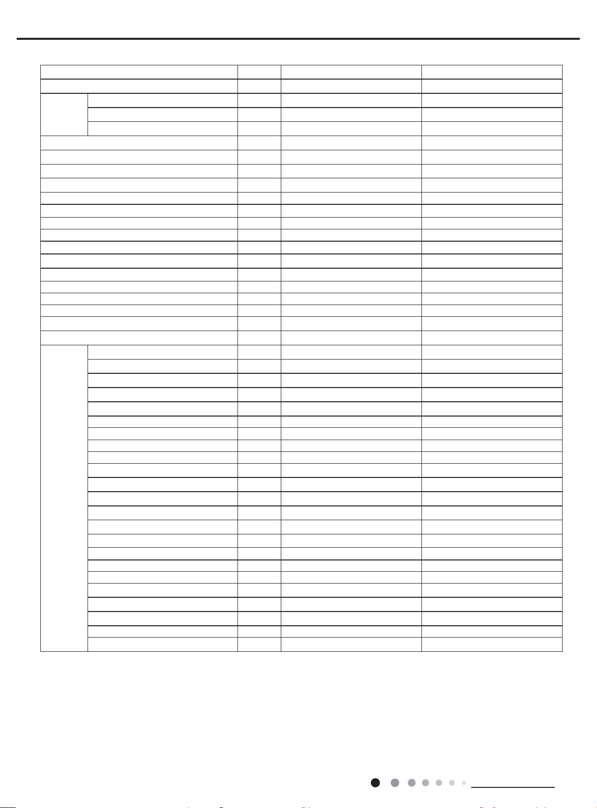
Service Manual
Model ACZEM4C4R24/ACZCI4C4R24 ACZEM4H4R24/ACZCI4H4R24
Product Code CB162008500_L17107 CB162007900_L14385
Power
Supply
Rated Voltage V
~
Rated Frequency Hz 60 60
208/230 208/230
Phases 1 1
Power Supply Mode Outdoor Outdoor
Cooling Capacity(Min~Max) Btu/h 22000(8630~23200) 22000(8630-23200)
Heating Capacity(Min~Max) Btu/h / 23000(8650~26000)
Cooling Power Input(Min
Heating Power Input(Min
Max) W 2310(600~2700) 2310(600~2700)
~
Max) W / 2300(610~2750)
~
Cooling Current Input A 10.25 10.25
Heating Current Input A / 10.20
Rated Input W 2700 2750
Rated Current A 11.98 12.20
Air Flow Volume (S/H/M/L) CFM 1000/800/700/600 1000/800/700/600
Dehumidifying Volume Pint/h 5.28 5.28
EER (Btu/h)/W 9.52 9.52
COP (Btu/h)/W / 10
SEER
15
15
SCOP / 8.5
Application Area yd
2
32 2/7-50 1/4 32 2/7-50 1/4
Indoor Unit Model ACZEM4C4R24 ACZEM4H4R24
Indoor Unit Product Code CB162N08500_L17107 CB162N07900_L14385
Fan Type Cross-ow Cross-ow
Fan Diameter Length(DXL) inch Ф3 6/7X30 1/8 Ф3 6/7X30 1/8
Cooling Speed(S/H/M/L) r/min 1500/1200/1050/900 1500/1200/1050/900
Heating Speed(S/H/M/L) r/min / 1450/1150/1020/950
Fan Motor Power Output W 60 60
Fan Motor RLA A 0.24 0.24
Fan Motor Capacitor μF AS/ /
Evaporator Form W Aluminum Fin-copper Tube Aluminum Fin-copper Tube
Evaporator Pipe Diameter inch Ф2/7 Ф2/7
Indoor Unit
Evaporator Row-n Gap inch 2-3/50 2-3/50
Evaporator Coil Length (LXDXW) inch 28 1/7X1X12 28 1/7X1X12
Swing Motor Model MP35XX MP35XX
Swing Motor Power Output W 3 3
Fuse Current A 3.15 3.15
Sound Pressure Level (S/H/M/L) dB (A) 52/46/42/36 52/46/42/36
Sound Power Level (S/H/M/L) dB (A) 62/56/52/46 62/56/52/46
Dimension (WXHXD) inch 39 5/7X12 2/5X8 3/5 39 5/7X12 2/5X8 3/5
Dimension of Carton Box (LXWXH) inch 42 1/5X15 3/5X12 1/3 42 1/5X15 3/5X12 1/3
Dimension of Package (LXWXH) inch 42 2/5X15 3/5X13 42 2/5X15 3/5X13
Net Weight lb 28.66 33.1
Gross Weight lb 36.38 40.79
4
Technical Information
Service Manual
Outdoor
Unit
Connection
Pipe
Outdoor Unit Model ACZCI4C4R24 ACZCI4H4R24
Outdoor Unit Product Code CB145W03900_L17107 CB145W04000_L14385
Compressor Manufacturer
Compressor Model QXA-B141zF030A QXA-B141zF030A
Compressor Oil 68EP 68EP
Compressor Type Rotary Rotary
Compressor LRA. A 25 25
Compressor RLA A 7.2 7.2
Compressor Power Input W 1440 1440
Compressor Overload Protector 1NT11L-6233 1NT11L-6233
Throttling Method Capillary Capillary
Set Temperature Range °F 60.8~86.0 60.8~86.0
Cooling Operation Ambient Temperature
Range
Heating Operation Ambient Temperature
Range
Condenser Form Aluminum Fin-copper Tube Aluminum Fin-copper Tube
Condenser Pipe Diameter inch Ф3/8 Ф3/8
Condenser Rows-n Gap inch 2-3/50 2-3/50
Condenser Coil Length (LXDXW) inch 33 2/7X1 2/3X26 33 2/7X1 2/3X26
Fan Motor Speed rpm 450/800 450/800
Fan Motor Power Output W 60 60
Fan Motor RLA A 0.37 0.37
Fan Motor Capacitor μF / /
Outdoor Unit Air Flow Volume CFM 1883 1883
Fan Type Axial-ow Axial-ow
Fan Diameter inch Φ20 1/2 Φ20 1/2
Defrosting Method / Automatic Defrosting
Climate Type T1 T1
Isolation I I
Moisture Protection IP24 IP24
Permissible Excessive Operating Pressure
for the Discharge Side
Permissible Excessive Operating Pressure
for the Suction Side
Sound Pressure Level (H/M/L) dB (A) 59/-/- 59/-/-
Sound Power Level (H/M/L) dB (A) 69/-/- 69/-/-
Dimension (WXHXD) inch 37 3/5X27 3/5X15 3/5 37 3/5X27 3/5X15 3/5
Dimension of Carton Box (LXWXH) inch 40 2/5X17 8/9X28 8/9 40 2/5X17 8/9X28 8/9
Dimension of Package (LXWXH) inch 40 1/2X18X29 1/2 40 1/2X18X29 1/2
Net Weight lb 108.0 114.7
Gross Weight lb 118 124.6
Refrigerant R410A R410A
Refrigerant Charge oz 56.4 65.3
Connection Pipe Length ft 24.6 24.6
Connection Pipe Gas Additional Charge oz/ft. 0.2 0.3
Outer Diameter Liquid Pipe inch 1/4 1/4
Outer Diameter Gas Pipe inch 5/8 5/8
Max Distance Height ft 32.8 32.8
Max Distance Length ft 82 82
Note: The connection pipe applies metric diameter.
PSIG 550 550
PSIG 240 240
ZHUHAI LANDA COMPRESSOR
CO.,LTD
°F 64~109 64~109
°F / 19.4~75.2
ZHUHAI LANDA COMPRESSOR
CO.,LTD
The above data is subject to change without notice. Please refer to the nameplate of the unit.
Technical Information
5
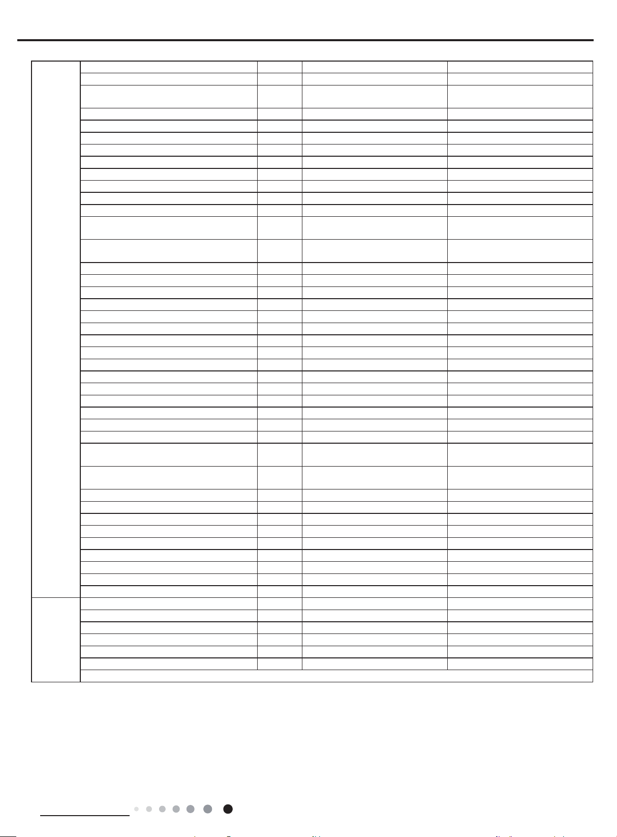
2.2 Operation Characteristic Curve
Cooling Heating
)A( tnerruC
)%( oitar yticapaC
Cooling Heating
Service Manual
11
10
•Conditions
Indoor DB 80F/WB 67 F
9
Outdoor : DB 95F/WB75F
8
Indoor air flow : Turbo
Pipe length : 24.6 ft.
7
6
5
4
3
2
1
0
220V
230V
240V
11
10
9
8
)A( tnerruC
7
6
5
4
3
2
1
0
0 10 20 30 40 50 60 70 80 90 100 1200 10 20 30 40 50 60 70 90 11080
Compressor speed (rps)
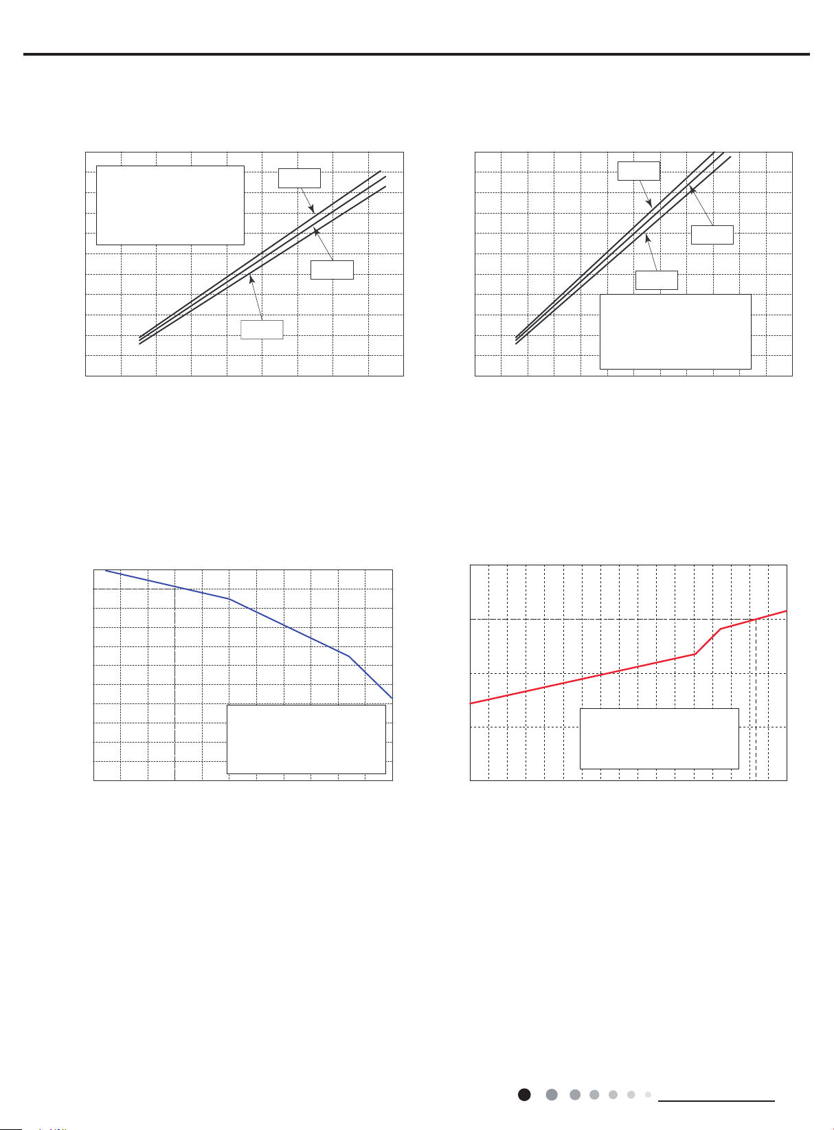
2.3 Capacity Variation Ratio According to Temperature
220V
230V
240V
•Conditions
Indoor : DB 70F/WB 60F
Outdoor : DB 47F/WB 43F
Indoor air flow : Turbo
Pipe length : 24.6 ft.
Compressor speed (rps)
105
100
95
90
85
80
75
70
65
60
55
50
89.6 91.4 93.2 95 96.8 98.6 100.4 102.2 104 105.8 107.6 109.4
Outdoor temp. (F)
Conditions
Indoor: DB 80F/WB66.9F
Indoor air flow : Turbo
Pipe length: 24.6ft.
120
)%( oitar yticapaC
100
80
60
40
19.4 23 32 41 50
Conditions
Indoor: DB 70F
Indoor air flow : Turbo
Pipe length: 24.6ft.
Outdoor temp. (F)
47
6
Technical Information
Service Manual
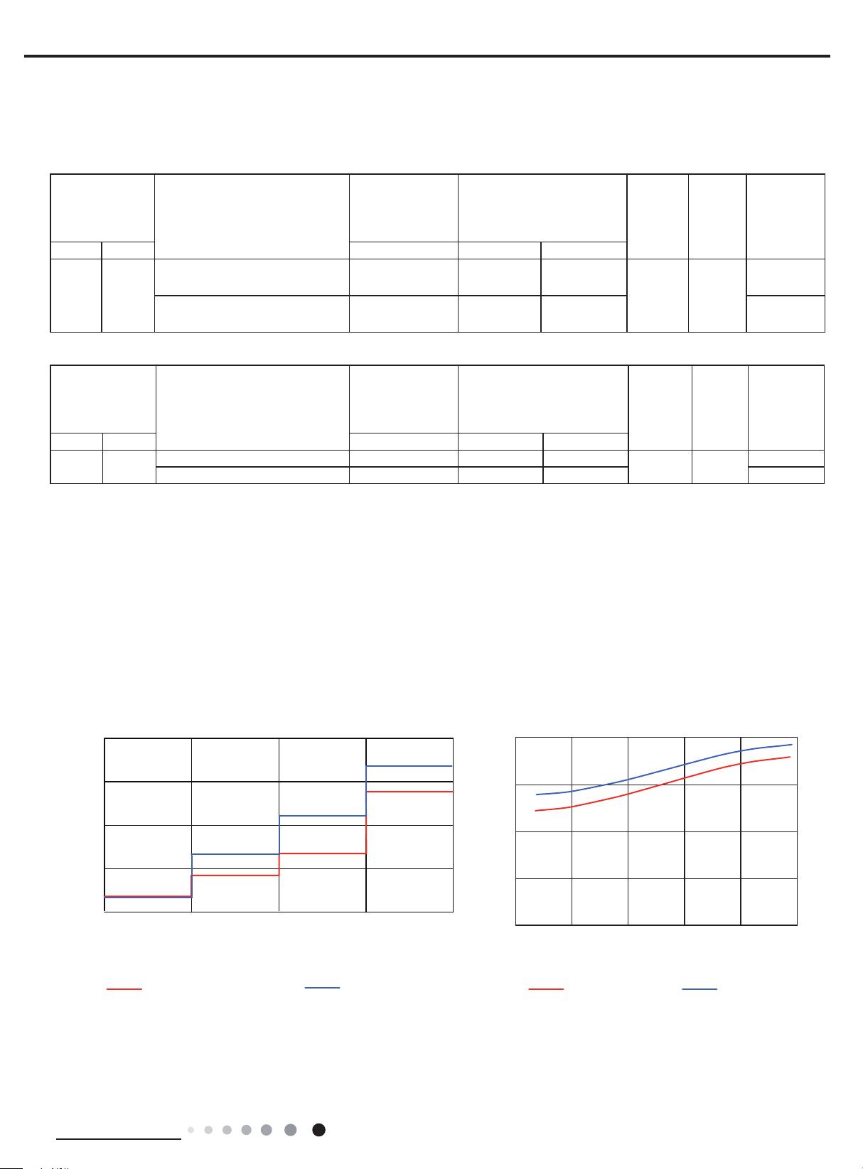
Indoor side noise
Noise/dB(A)
Outdoor side noise
2.4 Cooling and Heating Data Sheet in Rated Frequency
Cooling:
Rated cooling
condition (°F)
(DB/WB)
Indoor Outdoor P (MPa) T1 (°F) T2 (°F)
ACZEM4C4R18/ACZCI4C4R18
80/67 95/75
Heating:
Rated heating
condition(°F)
(DB/WB)
Indoor Outdoor P (MPa) T1 (°F) T2 (°F)
70/60 47/43
Instruction:
T1: Inlet and outlet pipe temperature of evaporator
T2: Inlet and outlet pipe temperature of condenser
P: Pressure at the side of big valve
Connection pipe length: 24.6ft.
ACZEM4H4R18/ACZCI4H4R18
ACZEM4C4R24/ACZCI4C4R24
ACZEM4H4R24/ACZCI4H4R24
ACZEM4H4R18/ACZCI4H4R18 2.2 to 2.4
ACZEM4H4R24/ACZCI4H4R24 2.5 to 2.7 111.2 to 107.6 32 to 37.4 86
Model
Model
Pressure of gas
pipe connecting
indoor and
outdoor unit
0.9 to 1.1 53.6 to 57.2 109.4 to 105.8
0.8 to 1.0 50 to 53.6 181.4 to 113 92
Pressure of gas
pipe connecting
indoor and
outdoor unit
Inlet and outlet pipe
temperature of heat
exchanger
Inlet and outlet pipe
temperature of heat
exchanger
100.4 to 98.6
35.6to 39.2
Fan
speed of
indoor
unit
Turbo High
Fan speed
of indoor
unit
Turbo High
speed of
outdoor
speed of
Fan
unit
Fan
outdoor
unit
Compressor
revolution
(rps)
77
Compressor
revolution
(rps)
80
2.5 Noise Curve
55
50
45
40
35
Low Middle High
Indoor fan motor rotating speed
ACZEM4C4R18
ACZEM4H4R18
Super Hig h
ACZEM4C4R24
ACZEM4H4R24
70
60
50
40
Noise/dB(A)
30
0 20 40 60 100 80
Compressor frequency/Hz
ACZCI4C4R18
ACZCI4H4R18
ACZCI4C4R24
ACZCI4H4R24
Technical Information
7

3. Outline Dimension Diagram
3.1 Indoor Unit
W D
Service Manual
H
Ф2 1/6
2
1 2/9
5 3/7
Ф2 3/4
27 1/3
27
7 2/3
ACZEM4C4R18
ACZEM4H4R18
Ф2 1/6
3 6/7
7 2/7
ACZEM4C4R24
ACZEM4H4R24
Ф2 3/4
3 1/2
8
2 5/9
Model W H D
ACZEM4C4R18
ACZEM4H4R18
ACZEM4C4R24
ACZEM4H4R24
37 11 2/3 8
39 5/7 12 2/5 8 3/5
Technical Information
Unit:inch
Service Manual
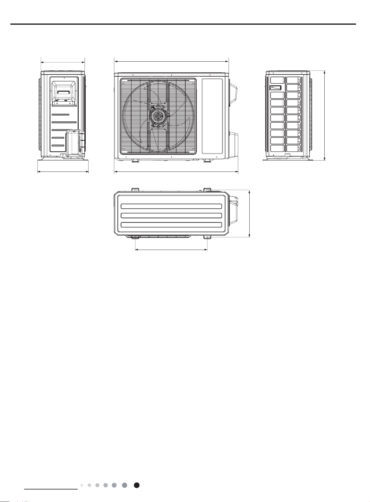
13 2/5 35
3.2 Outdoor Unit
27 3/5
15 3/5
37 3/5
14 1/2
Unit:inch
22
Technical Information
9
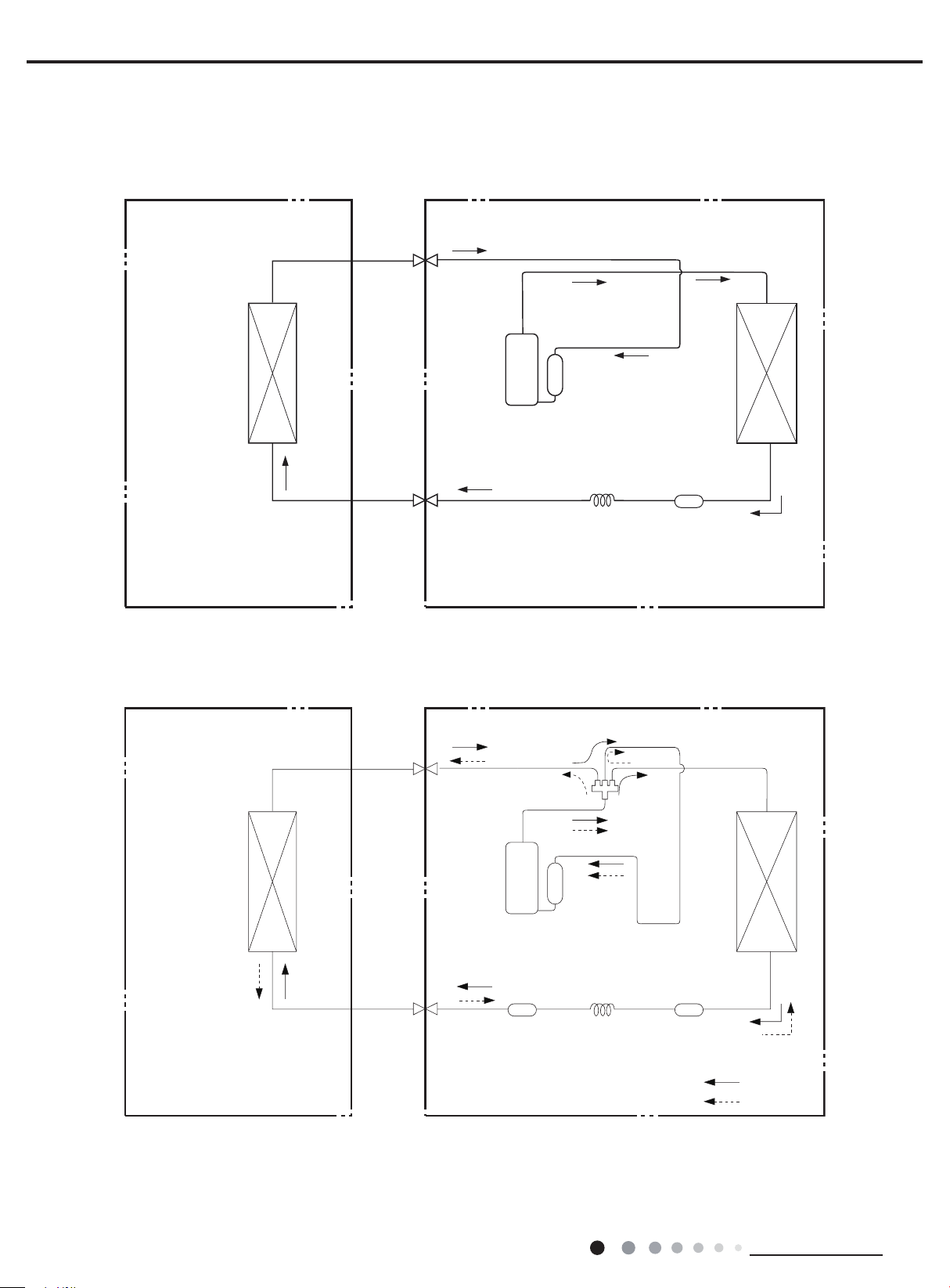
4. Refrigerant System Diagram
Indoor unit
Outdoor unit
Cooling only model
Gas pipe
side
Valve
Service Manual
Heat
exchanger
(evaporator)
Cooling and heating model
Indoor unit
Liquid pipe
side
Valve
Gas pipe
side
Valve
Discharge
Suction
Compressor
Accumlator
Outdoor unit
Capillary
4-Way valve
Heat
exchanger
(condenser)
Strainer
10
Discharge
Heat
Suction
Accumlator
exchanger
(evaporator)
Compressor
Liquid pipe
side
Valve
Refrigerant pipe diameter
Liquid pipe : 1/4"
Gas pipe : 1/2"(For ACZEM4C4R18/ACZCI4C4R18 ACZEM4H4R18/ACZCI4H4R18)
Gas pipe : 5/8"(For ACZEM4C4R24/ACZCI4C4R24 ACZEM4H4R24/ACZCI4H4R24)
Strainer Strainer
Capillary
Heat
exchanger
(condenser)
COOLING
HEATING
Technical Information
Service Manual
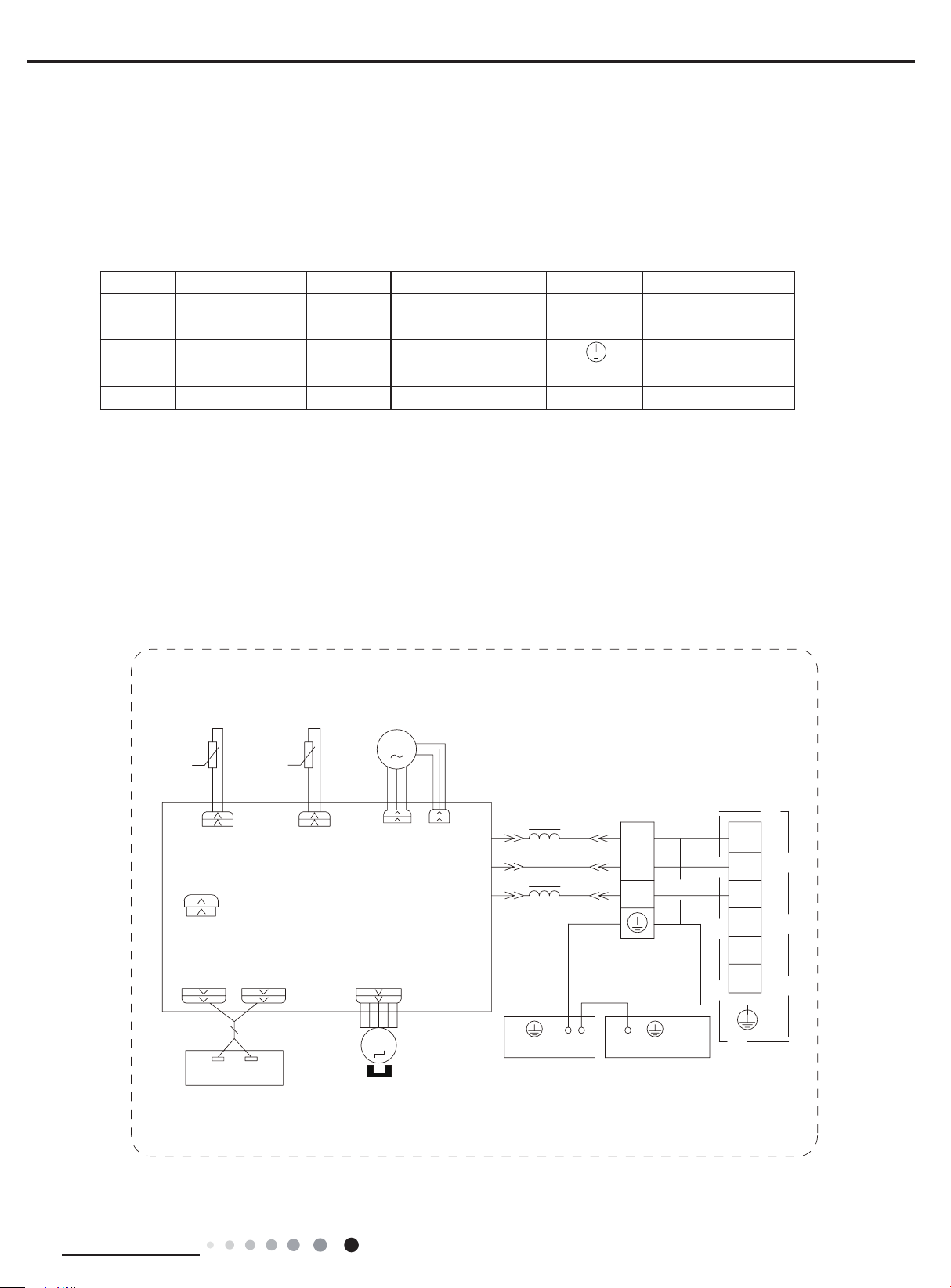
5. Electrical Part
5.1 Wiring Diagram
●Instruction
Symbol Symbol Color Symbol Symbol Color Symbol Name
WH White GN Green CAP Jumper cap
YE Yellow BN Brown COMP Compressor
RD Red BU Blue Grounding wire
YEGN Yellow/Green BK Black / /
VT Violet OG Orange / /
Note: Jumper cap is used to determine fan speed and the swing angle of horizontal lover for this model.
● Indoor Unit
Models: ACZEM4C4R18 ACZEM4H4R18
TEMP.
SENSOR
RT1 RT2
TUBE
CAP
JUMP
DISP1 DISP2
ROOMTUBE
SENSOR
ROOM
PRINTED CIRCUIT BOARD
TEMP.
AP2
SWING-UD
FAN MOTOR
M1
PGFPG
COM-OUT
AC-L
N
MAGNETIC
RING
L
BU
BK
L
BN
YEGN
XT
N(1)
TERMINAL
BLOCK
YEGN
CONNECTING
CABLE
2
3
N(1)
2
3
L1
L2
G
OUTDOOR UNIT
DISPLAY BOARD
Technical Information
DISPLAY
AP1
RECEIVER AND
M2
SWING
MOTOR
G
EVAPORATOR
G
ELECTRIC BOX
G
11
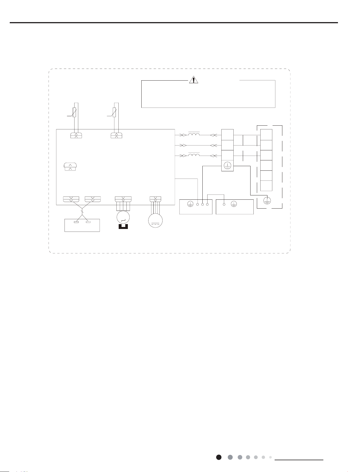
Models: ACZEM4C4R24 ACZEM4H4R24
TUBE
SENSOR
TEMP.
ROOM
SENSOR
RT1 RT2
TUBE
CAP
JUMP
DISP1 DISP2
AP1
RECEIVER AND
DISPLAY BOARD
PRINTED CIRCUIT BOARD
SWING-UD2
DISPLAY
TEMP.
ROOM
AP2
M2
SWING
MOTOR
WARNING
Please don't touch any electronic component
or terminal when the machine is running,
stopping or has been powered off for less
than 3 minutes to prevent electric shock !
N
COM-OUT
AC-L
MAGNETIC
RING
L
BU
BK
L
BN
CONNECTING
XT
CABLE
N(1)
2
3
YEGN
PE
YEGN
DC-MOTOR
G
EVAPORATOR
TERMINAL
BLOCK
YEGN
G
ELECTRIC BOX
M1
FAN MOTOR
N(1)
2
3
L1
L2
G
Service Manual
OUTDOOR UNIT
G
12
Technical Information

Service Manual
●Outdoor Unit
Models: ACZCI4C4R18 ACZCI4C4R24
G
WARNING
L2
L1
POWER
TERMINAL
BLOCK
2
3
L1
L2
G
XT1
Please don't touch any electronic
component or terminal when the
machine is running , stopping or
has been powered off for less
than 30 minutes to prevent the
risk of electric shock !
TERMINAL
BLOCK
2
3
INDOOR UNIT
XT
Models: ACZCI4H4R18 ACZCI4H4R24
BN
YEGN
G
BU
L1
L5
L1
L5
L5
L1
MAGNETIC
RING
BK
BN
BU
OUTTUBE
TEMP.SENSOR
WH
COM_INNER
AC_L
N
PE
YEGN
G
OUTROOM
TEMP.SENSOR
EXHAUST
TEMP.SENSOR
RT3RT2RT1
BK
T_SENSOR
OVC_COMP
AP1
PRINTED CIRCUIT BOARD
OFAN
G
M1
FAN MOTOR
YEGN
G
WH
SAT
WH
U
COMP
V
YE
L2L2
U V W
INDC2
INDC1
WH
L3
L4
L4
L
REACTOR
RDBU
L2
RDYEBU
COMP.
G
YEGN
W
MAGNETIC
RING
X1
OG
MAGNETIC
RING
G
Please don't touch any electronic
WARNING
component or terminal when the
machine is running , stopping or
has been powered off for less
than 30 minutes to prevent the
risk of electric shock !
TERMINAL
BLOCK
N(1)
2
3
INDOOR UNIT
XT
POWER
G
L1
TERMINAL
L2
BLOCK
N(1)
2
3
L1
L2
G
XT1
YEGN
BU
BN
G
L5
L1
L1
L5
L1
L5
MAGNETIC
RING
TEMP.SENSOR
OUTTUBE
RT1 RT2 RT3
WH BK
BK
BN
BU
T_SENSOR
COM_INNER
AC_L
N
PE
YEGN
G
OVERLOAD PROTECTOR
WH
BU
YE
SAT
U
V
COMP
RD
L2L2L2
COMP.
G
YEGN
W
MAGNETIC
RING
EXHAUST
TEMP.SENSOR
OUTROOM
WH
TEMP.SENSOR
X1
RDYEBU
WVU
OVC_COMP
(COMP-U)(COMP-V) (COMP-W)
AP1
PRINTED CIRCUIT BOARD
4V
4YV
4-WAY
VALVE
OFAN
M1
FAN MOTOR
G
YEGN
G
INDC1
WH
L4
INDC2
L3
L4
L
REACTOR
OG
MAGNETIC
RING
G
These wiring diagrams are subject to change without notice; please refer to the one supplied with the unit.
Technical Information
13
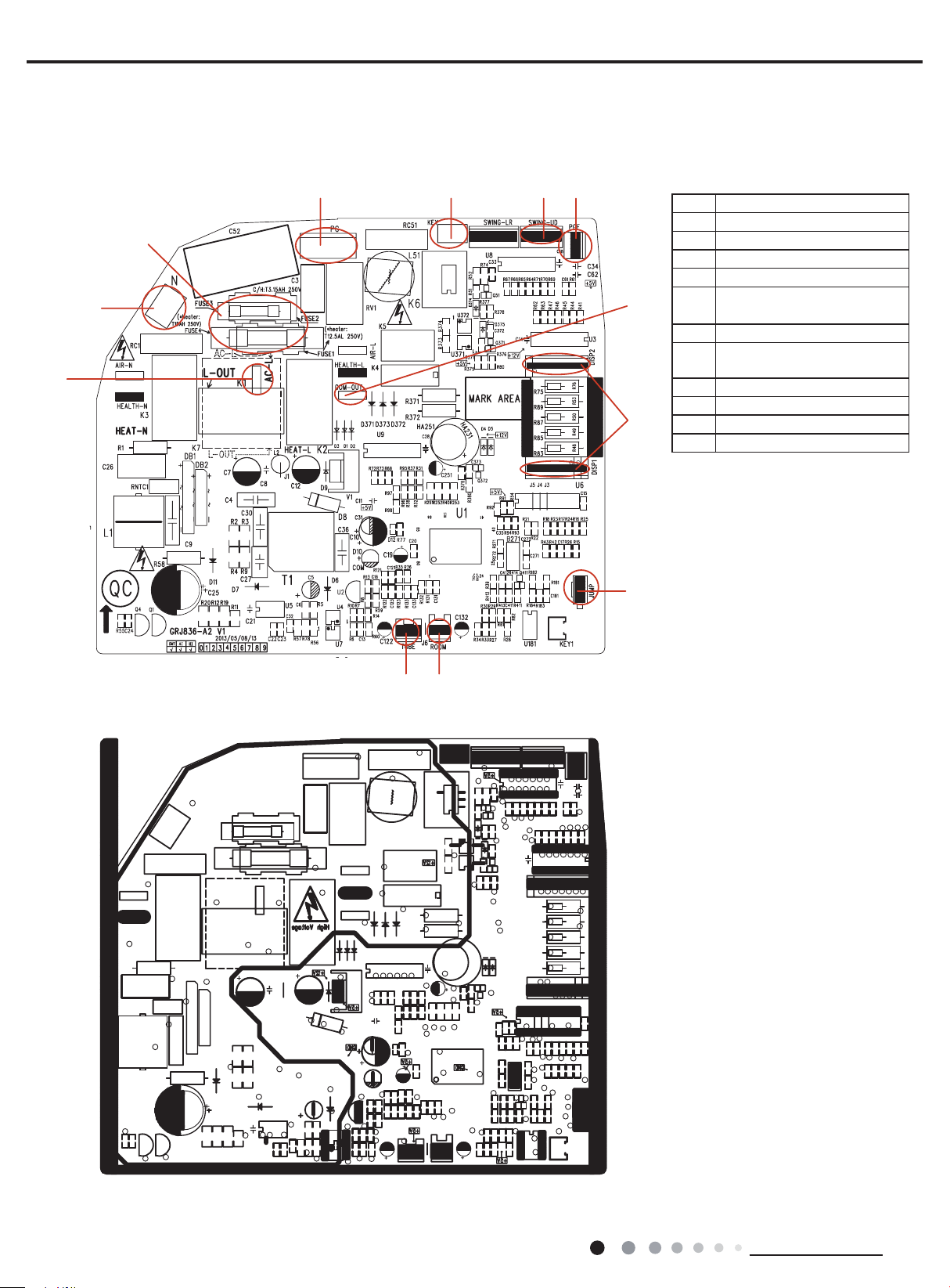
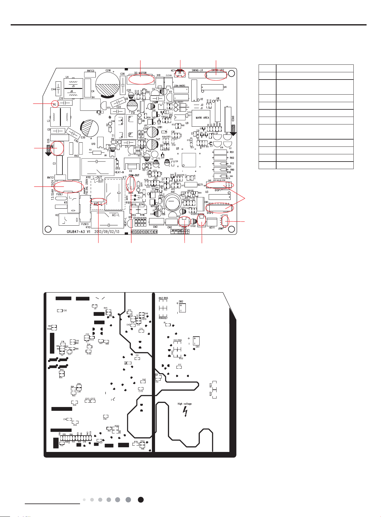
5.2 PCB Printed Diagram
● Indoor Unit
Models: ACZEM4C4R18 ACZEM4H4R18
● Top view
3
2
1
4 5 6 7
Service Manual
1 Live wire interface
2 Neutral wire interface
3 Fuse
4 PG Motor
5 Auto button
Up and down swing terminal
8
9
6
interface
7 PG feedback
IDU and ODU communication
8
interface
9 Display terminal interface
10 Jumper
11 Ambient temp. sensor
12 Tube temp. sensor
● Bottom view
10
1112
14
Technical Information
Service Manual
1 2 3
Models: ACZEM4C4R24 ACZEM4H4R24
● Top view
12
11
10
1 DC fan interface
2 Auto button
Up and down swing terminal
3
interface
4 Display terminal interface
5 Jumper cap
6 Ambient temp. sensor
7 Tube temp. sensor
IDU and ODU communication
8
interface
9 Live wire interface
10 Fuse
11 Neutral wire interface
12 Earth wire terminal interface
4
● Bottom view
5
6789
Technical Information
15
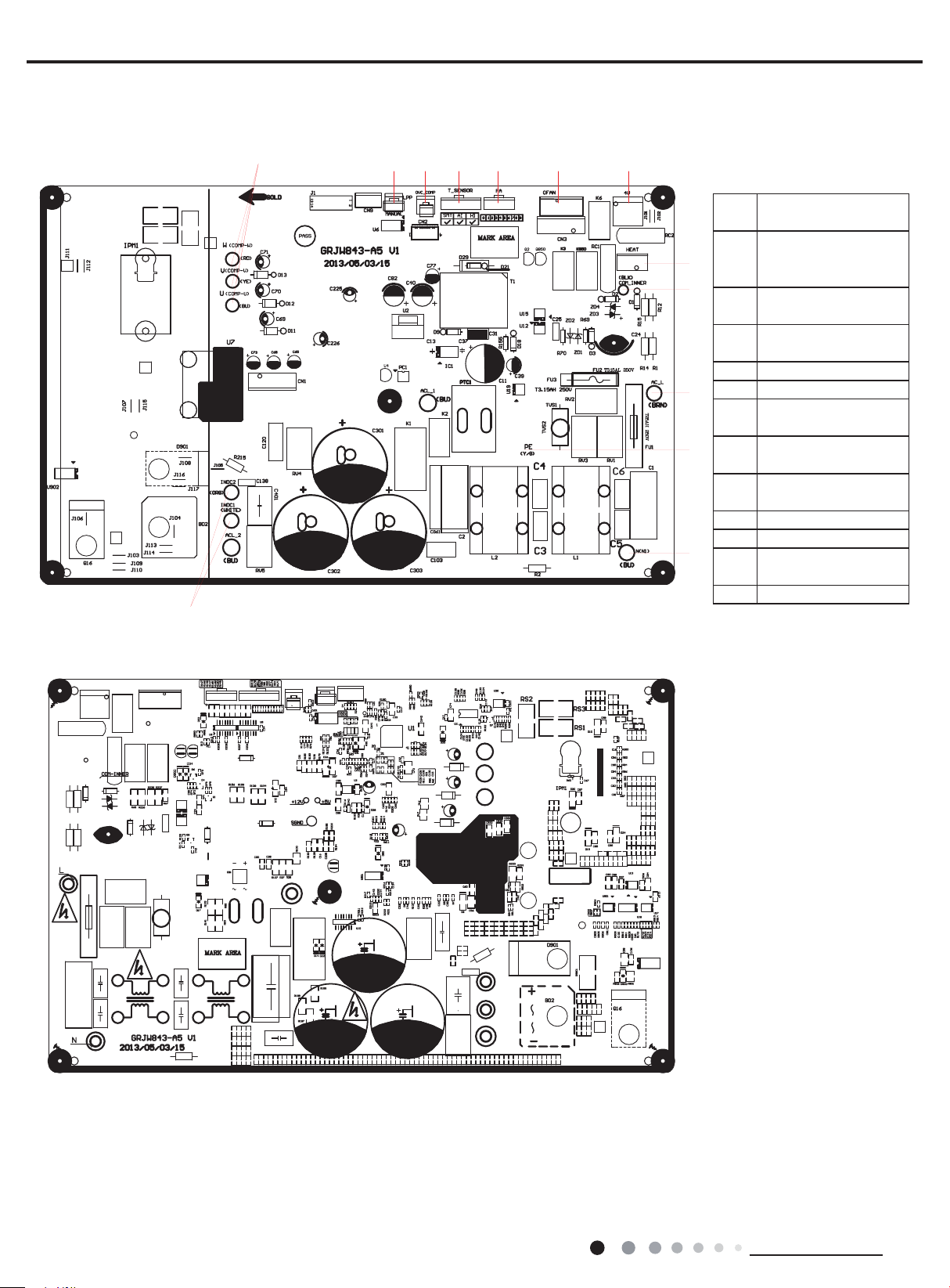
Outdoor Unit
1 2 3 4 5 6 7
● Top view
13
Compressor wiring
1
connection terminal
ODU heat exchanger
2
8
9
10
11
12
middle copper pipe
temp. sensor terminal
Compressor overload
3
protection terminal
ODU temp. sensor
4
terminal
5 EXV terminal
6 Outdoor fan terminal
Four-way valve
7
terminal
Chassis electric heating
8
wiring terminal
Communication cable
9
with IDU
10 Power supply live wire
11 Earth wire
Power supply neutral
12
wire
13 PFC inductance wire
Service Manual
● Bottom view
16
Technical Information
Service Manual
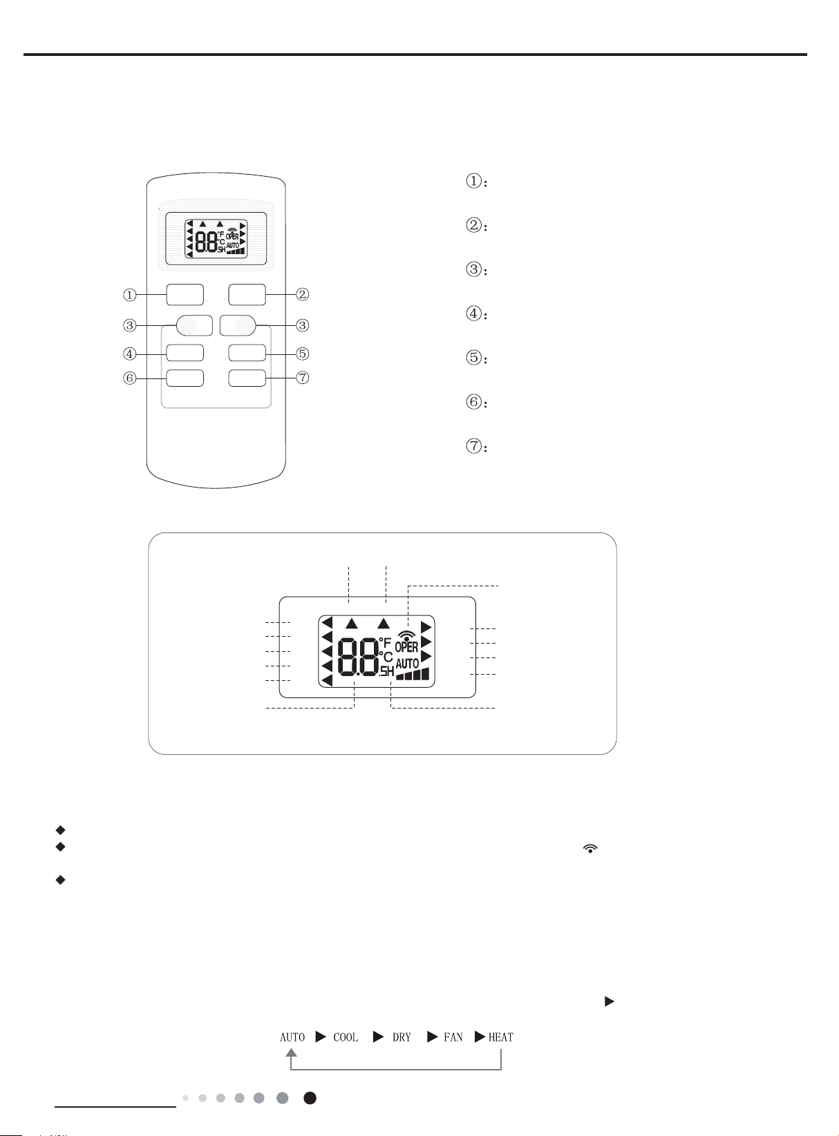
Buttons on Remote Controller
6. Function and Control
6.1 Remote Controller Introduction
T-ON T-OFF
AUTO
COOL
DRY
FAN
HEAT
SWING
SLEEP
LOCK
SPEED
ON/OFF button
MODE button
+/- botton
ON/OFF
_
FAN SWING
SLEEP
MODE
+
TIMER
Icon Display on Remote Controller
For auto operation
For cooling
For drying
For fan only
For heating
AUTO
COOL
DRY
FAN
HEAT
Timer on Timer off
T-ON T-OFF
SWING
SLEEP
LOCK
SPEED
FAN button
SWING button
SLEEP button
TIMER button
Sending signal
For air swing
For sleeping
For locking
For setting fan speed
Set temperature
Set time
Operation introduction of remote controller
Note:
When power is connected(stand by condition), you can operate the air conditioner through the remote controller.
When unit is on, each time you press the button on remote controller, the sending signal icon on the display of remote controller
will blink once. If the air conditioner gives out a beep sound, it means the signal has been sent.
When unit is off, set temperature will be displayed on the remote controller(If the light of indoor unit display is turned on, the
corresponding icon will be displayed); When unit is on, it will display the icon of the on-going function.
1. ON/OFF Button
Press this button to turn unit on/off.
2. MODE Button
Pressing this button once can select your required mode circularly as below(the corresponding icon
selected):
(Only for models with heating function.)
Technical Information
will be lit up after the mode is
17
When selecting auto mode, air conditioner will operate automatically according to Ambient Temperature. Set temperature can't be
adjusted and won't be displayed either. Press FAN button to adjust fan speed. (This function is not available in this air conditioner.)
When selecting cool mode, air conditioner will operate under cool mode. Then press + or -- button to adjust set temperature. Press
FAN button to adjust fan speed.
When selecting dry mode, air conditioner will operate at low fan speed under dry mode. In dry mode, fan speed can't be adjusted.
When selecting fan mode, air conditioner will operate in fan mode only. Then press FAN button to adjust fan speed.
When selecting heat mode, air conditioner will operate under heat mode. Then press + or -- button to adjust set temperature. Press
FAN button to adjust fan speed.
3. +/- button
Pressing + or - button once will increase or decrease set temperature by 1 °F(°C). Hold + or -- button for 2s, set temperature on
remote controller will change quickly. Release the button after your required set temperature is reached.
When setting Timer On, Timer Off or Clock, press + or -- button to adjust the time (See TIMER Button for setting details).
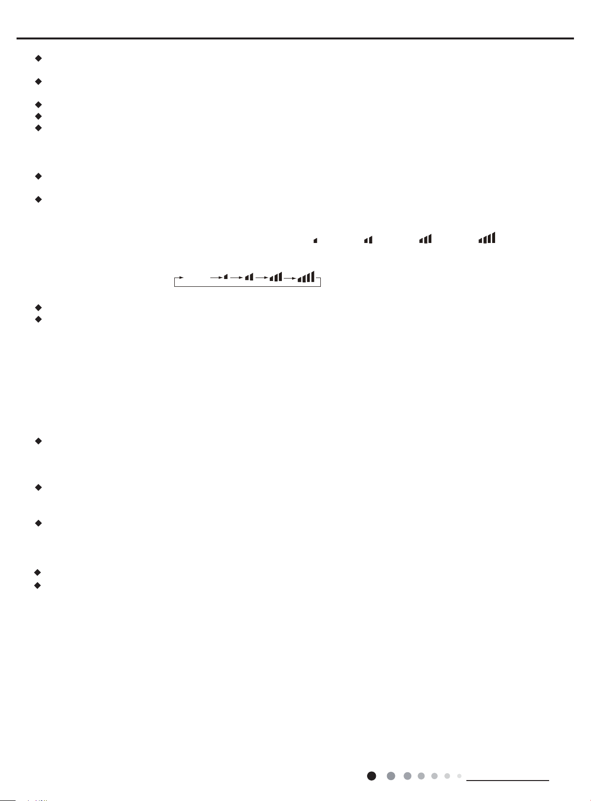
4. FAN Button
Pressing this button can select fan speed circularly as: AUTO, SPEED 1(
in this air conditioner. Speed 4 is the same with speed 3).
AUTO
Note:
Under Auto mode, air conditioner will select proper fan speed automatically according to ambient temperature.
Fan speed can't be adjusted under Dry mode.
), SPEED 2( ), SPEED 3( ), SPEED 4( ) (unavailable
Service Manual
5. SWING Button
Press this button to turn on up&down air swing.
6. SLEEP Button
Under Cool, Heat, Dry mode, press this button to turn on Sleep function. Press this button to cancel Sleep function. Under Fan and
Auto mode, this function is unavailable.
7. TIMER Button
When unit is on, press this button to set Timer Off. T-OFF and H icon will be blinking. Within 5s, press + or - button to adjust the
time for Timer Off. Pressing + or - button once will increase or decrease the time by 0.5h. Hold + or -- button for 2s, time will change
quickly. Release the button after your required set time is reached. Then press TIMER button to con rm it. T-OFF and H icon will stop
blinking.
When unit is off, press this button to set Timer On. T-ON and H icon will be blinking. Within 5s, press + or - button to adjust the time
for Timer On. Pressing + or - button once will increase or decrease the time by 0.5h . Hold + or - button for 2s, time will change quickly.
Release the button after your required set time is reached. Then press TIMER button to con rm it. T-ON and H icon will stop blinking.
Cancel Timer On/Off: If Timer function is set up, press TIMER button once to review the remaining time. Within 5s, press TIMER
button again to cancel this function.
Note:
Range of time setting is: 0.5~24h
The interval between two motions can't exceed 5s, otherwise the remote controller will exit setting status.
Function introduction for combination buttons
1.Child lock function
Press “+” and “-” buttons simultaneously can turn on or turn off child lock function.When child lock function is started up, LOCK
indicator on remote controller is ON.If you operate the remote controller, remote controller won’t send signal.
2.Temperature display switchover function
Under OFF status, press “-” button and “MODE” button simultaneously can switchbetween °C and °F.
Operation guide
1. After putting through the power, press "ON/OFF" button on remote controller to turn on the air conditioner.
2. Press "MODE" button to select your required mode: AUTO, COOL, DRY, FAN,HEAT.
3. Press "+" or "-" button to set your required temperature. (Temperature can’t beadjusted under auto mode).
4. Press "FAN" button to set your required fan speed: auto, low, medium and high speed.
5. Press "SWING" button to select fan blowing angle.
18
Technical Information
Service Manual
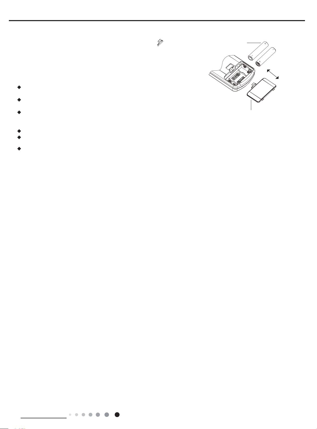
Replacement of Batteries in Remote Controller
1. Press the back side of remote controller on the spot marked with , and then
push out the cover of battery box along the arrow direction.
2. Replace two No.7 (AAA 1.5V) dry batteries and make sure the positions of + and -polar are correct.
3. Reinstall the cover of battery box.
Note:
During operation, point the signal sender of the remote controller at the receiving
window of the indoor unit;
The distance between signal sender and receiving window should be within 8m.
There should be no obstacle between them.
Signal may be interfered easily in the room where there is uorescent lamp
or wireless telephone; Remote controller should be close to indoor unit during
operation.
Replace new batteries of the same model when replacement is required.
When you don’t use remote controller for a long time, please take out the
batteries.
If the display on remote controller is fuzzy or if there's no display, please replace
batteries.
battery
reinstall
remove
cover of battery box
Technical Information
19

Service Manual
Dual-8 nixie
6.2 Brief Description of Modes and Functions
1 General introduction
(1) Buzzer
When the controller is energized or receives any command or signal from the buttons or the remote controller, the buzzer will give out a
beep.
(2) Display
After energizing, the unit will display all icons. Under standby status, running
indicating icon is displayed in red. If the unit is started by remote controller,
running indicating icon is displayed in green (the color may be different for
different models); meanwhile, the icon of current running mode will be displayed
(mode icons: cooling, heating and dry mode).
(3) Temperature parameters
Indoor set temperature (Tset)
◆
Indoor ambient temperature (Tamb.)
◆
Indoor evaporator inner tube temperature (Tinner tube)
◆
Indoor condenser outer tube temperature (Touter tube)
◆
Outdoor discharge pipe temperature (Tdischarge)
◆
Outdoor IMP module temperature (Tmodule)
◆
Heating icon
(Display content or position may be different from above graphics, please
refer to actual products)
Cooling icon
tube display
Operation icon
Drying icon
Receiver
window
Display
2.Introduction of basic mode function
Once the compressor is energized, there should be a minimum interval of 3 mins between two start-ups.
If the unit is with memory function and is off before power failure, the compressor can be restarted without an interval of 3 mins after the
system is energized; if the unit is on before power failure, the compressor will be restarted with an interval of 3 mins.
Once started, the compressor won’t stop within 7 mins according to the change of room temp.
(1) Auto mode
Auto mode conditions and process
①
In this mode, the unit will automatically select its operation mode (cooling, heating or fan) according to the change of indoor ambient
temperature. There is a 30-second delay protection for mode switchover.
When Tamb.≥78OF, the unit runs in cooling mode; in this case, the factory default set temperature is 77OF.
◆
For cooling and heating model: when Tamb.≤71.6OF, the unit runs in heating mode; in this case, the factory default set temperature is
◆
O
68
F.
For cooling only model: when Tamb.≤71.6OF, the unit runs in fan mode; in this case, the factory default set temperature is 77OF.
◆
When 71.6OF
◆
Tamb.<78
<
O
F: the unit will run in fan mode when it enters auto mode just after power on; the unit will keep the
previous operation mode when it enters auto mode from cooling, heating or fan mode; the unit will run in fan mode when it enters auto
mode from dry mode.
The indoor unit displays the operation icon, operation mode icon and set temperature, but set temperature can’t be adjusted.
②
Protection functions are the same as those in any other mode. (See function protection of this section)
③
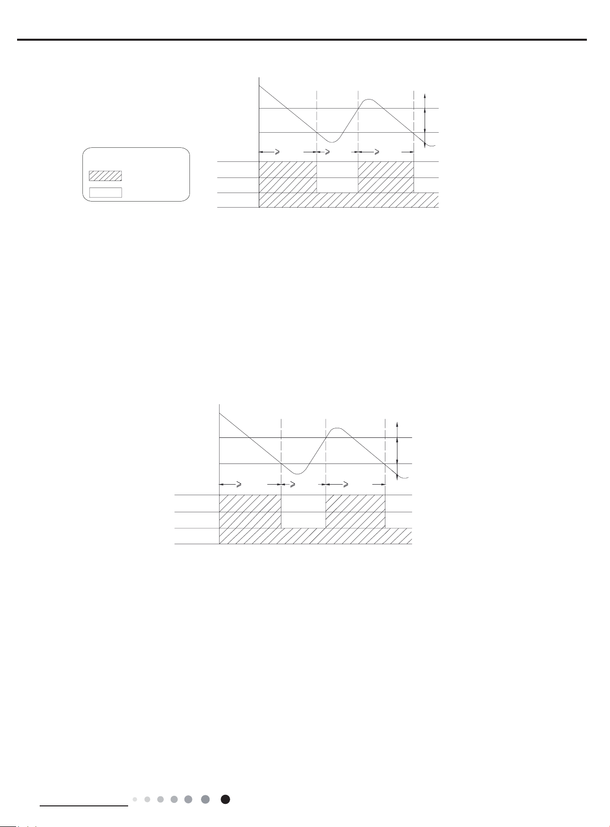
(2) Cooling mode
Cooling conditions and process
①
When Tamb. ≥Tset-32.9OF, the unit starts cooling. In this case, the compressor and the ODU fan motor run, and the IDU fan motor
◆
runs at set speed.
When Tamb. ≤Tset-35.6OF, the compressor and the ODU fan motor stop after a few seconds, while the IDU fan motor runs at set
◆
speed.
When Tset-35.6OF
◆
When the unit stops due to malfunction or protection, the compressor and ODU fan motor stop, while the IDU maintains its present
◆
Tamb.<Tset-32.9
<
O
F, the unit will maintain its present operation status.
operation status.
In cooling process, when Tamb. is quite different from Tset, the compressor will run in relatively high frequency for quick cooling;
◆
when Tamb. is near Tset, the compressor frequency will decrease automatically for high coziness and efciency.
In this mode, the 4-way valve is de-energized (cooling only unit is without 4-way valve). Temperature setting range is 60.8
~
86
O
F
.
20
Technical Information
Service Manual
Tpreset -32.9F
Tpreset –35.6 F
Graphic instruction:
(Same as below)
Indicates operation
Indicates stop
The indoor unit displays operation icon, cooling icon and set temperature.
②
Protection functions (See function protection of this section)
③
Compressor
Outdoor fan motor
Indoor fan motor
Tamb.
7 min. 3 min. 7 min.
Set fan speed
Start cooling
Original operating status
Stop cooling
(3) Dry Mode
Dry conditions and process
①
When Tamb. ≥Tset-32.9OF, the unit starts drying and cooling. In this case, the compressor and the ODU fan motor run, and the IDU fan
◆
motor runs at low speed.
When Tamb. ≤Tset-35.6OF, the compressor and the ODU fan motor stop after a few seconds, while the IDU fan motor runs at low speed.
◆
When Tset-35.6OF
◆
When the unit stops due to malfunction or protection, the indoor unit maintains its present operation status and displays malfunction
◆
Tamb.<Tset-32.9
<
O
F, the unit will maintain its present operation status.
code.
In this mode, the 4-way valve is de-energized (cooling only unit is without 4-way valve). Temperature setting range is 60.8
~
86OF.
Tpreset -32.9F
Tpreset –35.6 F
Compressor
Outdoor fan motor
Indoor fan motor
The indoor unit displays operation icon, dry icon and set temperature.
②
Protection functions (See function protection of this section)
③
Tamb.
7 min. 3 min. 7 min.
Low speed
Start Drying
Original operating status
Stop Drying
(4) Fan mode
Fan conditions and process
①
In this mode, IDU fan motor runs at set speed while the compressor and ODU fan motor stop operation. The 4-way valve is de-energized
(cooling only unit is without 4-way valve). Temperature setting range is 60.8
The indoor unit displays operation icon and set temperature.
②
Protection functions (See function protection of this section)
③
~
86
O
F.
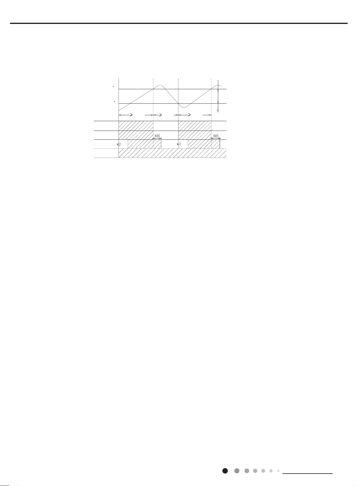
(5) Heating mode (not available for cooling only type)
Heating conditions and process
①
When Tamb.≤Tset+38.3OF, the unit starts heating operation. In this case, the 4-way valve, compressor and ODU fan motor run
◆
simultaneously; the IDU fan motor runs after a while to prevent blowing out cold air.
When Tamb. ≥Tset+41OF, the compressor and ODU fan motor stop after a few seconds; the 4-way valve remains energized; the IDU
◆
Technical Information
21
Service Manual
fan motor blows residual heat for a while at set speed to prevent high temperature inside the unit.
When Tset+38.3OF
◆
When the unit stops due to malfunction or protection, the compressor, IDU fan motor and ODU fan motor stop operation.
◆
In heating process, when Tamb. is quite different from Tset, the compressor will run in relatively high frequency for quick heating;
◆
Tamb.<Tset+41
<
O
F, the unit will maintain its previous operation status.
when Tamb. is near Tset, the compressor frequency will decrease automatically for high coziness and efciency.
In this mode, the 4-way valve is energized. Temperature setting range is 60.8
T
preset+41 F
T
preset
+38.3 F
T
amb
.
7 min. 3 min. 7 min.
Compressor
Outdoor unit
Intdoor unit
Reversing
The indoor unit displays operation icon, heating icon and set temperature.
②
Defrost conditions and process
③
min.
valve
min.
~
O
86
F.
Stop heating
Original operating status
Start heating
Set fan speedSet fan speed
In order to ensure heating effect, the unit will defrost automatically according to the frost status of outdoor unit. heating indicator is ON
10s and OFF 0.5(for 18K) and indoor unit display “H1“(for 24K) during defrosting.
Protection functions (See function protection of this section)
④
(6) Compressor control function
(1) The controller controls the operation frequency of compressor according to the relationship between ambient temperature and set
temperature and the changing speed of ambient temperature.
(2) When turning on the unit in cooling, heating or dry mode, the compressor starts after the ODU fan motor has operated for 5
seconds
.
(3) The compressor stops immediately when turning off the unit, switching to fan modes and unit stops for protection.
(4) In each mode: once started, the compressor won’t stop within 7 mins (note: including stop operation when reaching the temperature
point; not including malfunction protection, turning off the unit by remote controller or switching modes in which stopping operation of
compressor is needed).
(5) In each mode: once stopped, the compressor won’t start again within 3 mins; if the unit is with memory function, the compressor can
be restarted without delay when turning off the unit and then energizing again.
(7) 4-way valve control function(not available for cooling only type)
(1) The 4-way valve is de-energized in cooling, dry and fan mode;
(2) The 4-way valve is energized in heating mode;
(3) When turning off the unit in heating mode or switching to other mode from heating mode, the compressor stops and the 4-way valve
is de-energized after a while;
(4) When the unit stops for protection, the 4-way valve is de-energized after a while;
(5) When starting defrosting, the compressor stops and the 4-way valve is de-energized after a while;
(6) When existing defrosting, the compressor stops and the 4-way valve is energized after a while;
3.Other control functions
(1) Timer function
General timer and clock timer functions are compatible by equipping remote controller with different functions.
General timer: the timer precision is 30min and set unit ON/OFF after a desired hour.
①
Timer ON: timer ON can be set at unit OFF. If selected ON time is reached, the unit will start to run according to previous setting
◆
status. Time setting range is 0.5~24hr in 30-minute increments.
Timer OFF: timer OFF can be set at unit ON. If selected OFF time is reached, the unit will stop. Time setting range is 0.5~24hr in
◆
30-minute increments.
Clock timer: the timer precision is 1min and set unit ON/OFF at a certain time every day.
②
22
Technical Information
Service Manual
Timer ON: If timer ON is set during operation of the unit, the unit will continue to operate. If timer ON is set at unit OFF, upon ON
◆
time reaches the unit will start to run according to previous setting status.
Timer OFF: if timer OFF is set at unit OFF, the system will keep OFF status. If timer OFF is set at unit ON, upon OFF time reaches
◆
the unit will stop operation.
Timer change:
◆
Although timer has been set, the unit still can be turned on/off by pressing ON/OFF button of the remote controller. You can also reset
the timer.
If timer ON and timer OFF are set at the same time during ON status, the unit will keep running at current status. When OFF time
reaches, the unit will stop operation. Then upon ON time reaches, the unit will start operation automatically. The unit will operate circu-
larly like this every day.
If timer ON and timer OFF are set at the same time during OFF status, the unit will keep OFF status. When ON time reaches, the unit
will start operation. Then upon OFF time reaches, the unit will stop operation automatically. The unit will operate circularly like this
every day.
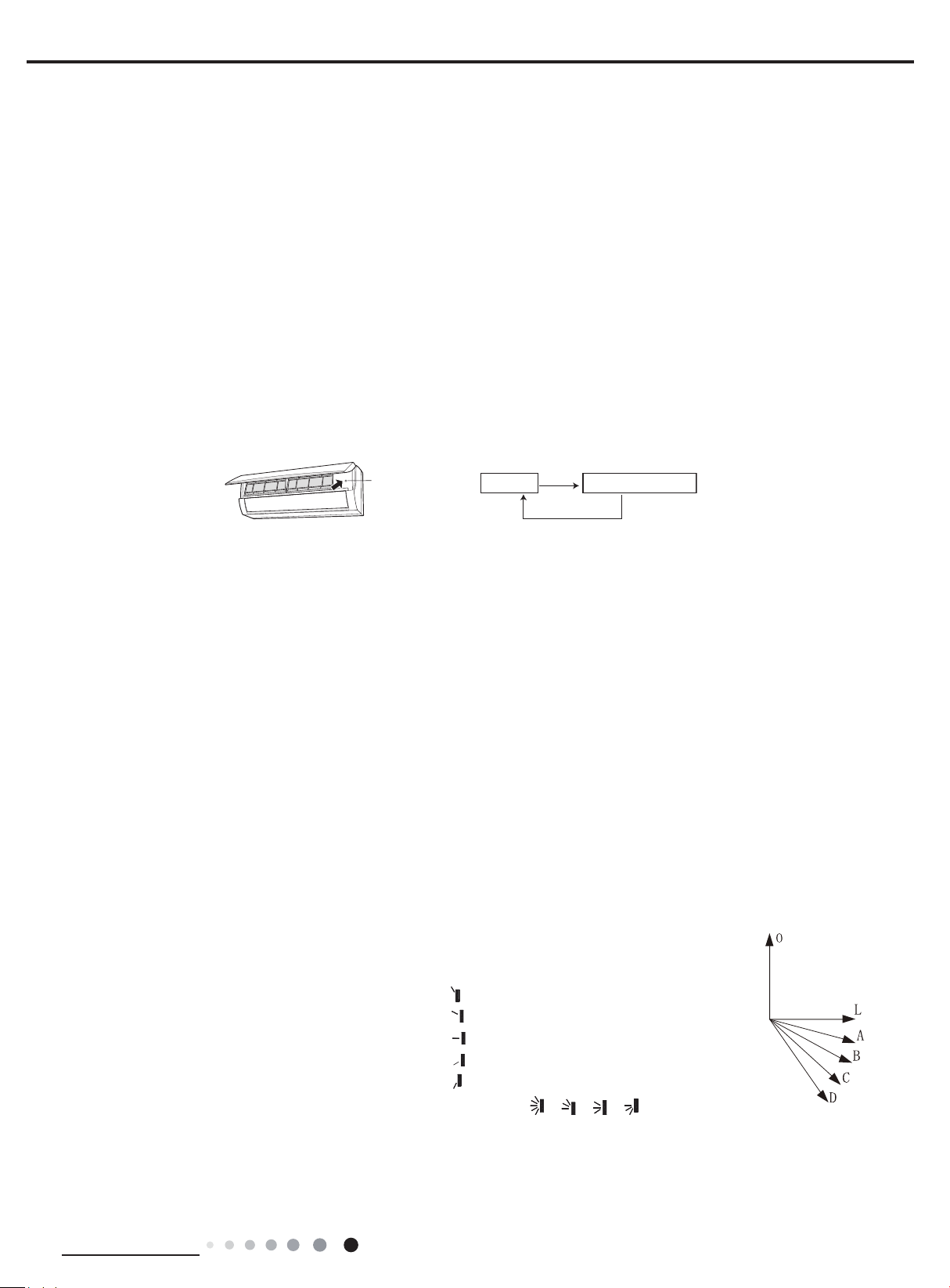
(2) Emergency operation switch
If pressing this button in OFF status, the unit will operate in AUTO mode and IDU fan motor will operate at auto speed; meanwhile, the
swing motor operates. Press this button again to turn off the unit.
Emergency
operation switch
OFF status
Press
ON status(Auto mode)
Press
(3) Sleep function
In this mode, the unit will automatically select appropriate sleep curve to operate according to different set temperature.
If sleep function is set in cooling, the system will increase set temperature automatically for operation in a certain degree.
①
If sleep function is set in heating mode, the system will decrease set temperature automatically for operation in a certain degree.
②
(4) Turbo function
This function can be set in cooling or heating mode. When turbo function is set, the system will operate in the highest fan speed.
(5) X-FAN function
This function can be set in cooling or dry mode. When X-FAN function is set, fan motor will run for a while and then stop operation
after the unit is turned off. During X-FAN operation, press X-FAN button on remote controller again to exit X-FAN function.
(6) Indoor fan speed control
Indoor fan speed can be set in super-high, high, medium and low speed through remote controller; auto fan speed can also be set
in cooling, heating and fan mode. In auto fan speed mode, the IDU fan motor will automatically select high, medium or low speed
according to the change of ambient temperature. (Note: super-high speed is only available in cooling and heating mode).
(7) Up & down swing
After energizing, up & down swing motor will rstly have the horizontal louver rotate anticlockwise to position 0 to close air outlet. If
①
swing function has not been set after turning on the unit, the horizontal louver will turn clockwise to position D in heating mode, or turn
clockwise to level position L in other modes.
If swing function is set when starting up the unit, the horizontal louver will swing between L and D.
②
O
There are 7 swing status of horizontal louver:
Positions L: corresponding setting on the remote controller:
◆
Positions A: corresponding setting on the remote controller:
◆
Positions B: corresponding setting on the remote controller:
◆
Positions C: corresponding setting on the remote controller:
◆
Positions D: corresponding setting on the remote controller:
◆
Swing between L and D, corresponding setting on the remote controller: , ,
◆
Stop at any position between L and D (angles between L and D are equiangular); corresponding setting on the remote controller:
◆
,
without display
Upon turning off the unit, the horizontal louver will close at position 0.
③
Technical Information
23

Service Manual
Swing function is available only when swing function is set and IDU fan motor is operating.
④
(8) Display of nixie tube on indoor unit
When energized & started for the rst time, the nixie tube defaults to displaying current set temperature.
◆
When set temperature display is set by remote controller, it will display set temperature; when switching to indoor ambient temperature
◆
display from other display status, indoor ambient temperature will be displayed for 3-5 seconds rstly and then set temperature display
returns; if other status are set by remote controller, it will still display original set temperature.
When malfunction occurs, the nixie tube will display corresponding error code. (refer to Error Code List)
◆
In auto defrosting mode, heating indicator is ON 10s and OFF 0.5(for 18K) and indoor unit display “H1“(for 24K). It is a normal
◆
phenomenon.
The display light can be closed by pressing light button.
◆
(9) Memory function
Power failure in unit ON status
①
Memorized items: unit ON status, mode, up & down swing, light, set temperature, set fan speed, general timer and Fahrenheit/ Celsius.
◆
General timer will be memorized and the timer time will be recalculated after re-energizing.
◆
Clock timer will not be memorized.
◆
Power failure in unit OFF status
②
Memorized items: unit OFF status, mode, up & down swing, light, set temperature, set fan speed, general timer and Fahrenheit/
◆
Celsius.
General timer will be memorized and the timer time will be recalculated after re-energizing.
◆
Clock timer will not be memorized.
◆
(10) Compulsory defrosting function
(1) Start up compulsory defrosting function
Under ON status, set heating mode with remote controller and adjust the temperature to 60.8OF. Press “+, -, +, -, +,-” button successively
within 5s and the complete unit will enter into compulsory defrosting status. Meanwhile, heating indicator is ON 10s and OFF 0.5(for 18K)
and indoor unit display “H1“(for 24K) (Note: If complete unit has malfunction or stops operation due to protection, compulsory defrosting
function can be started up after malfunction or protection is resumed.
(2) Exit compulsory defrosting mode
After compulsory defrosting is started up, the complete unit will exit defrosting operation according to the actual defrosting result, and the
complete unit will resume normal heating operation.
(11)
Refrigerant recycling function (applicable when changing installation location or in maintenance)
(1) Enter refrigerant recycling function
Within 5min after energizing (unit ON or OFF status is ok), continuously press LIGHT button for 3 times within 3s to enter refrigerant
recycling mode; Fo is displayed and refrigerant recycling function is started. At this moment, the maintenance people closes liquid valve.
After 5min, stick the thimble of maintenance valve with a tool. If there is no refrigerant spraying out, close the gas valve immediately and
then turn off the unit to remove the connection pipe.
(2) Exit refrigerant recycling function
After entering refrigerant recycling mode, when receive any remote control signal or enter refrigerant recycling mode for 25min, the unit
will exit refrigerant recycling mode automatically. If the unit is in standby mode before refrigerant recycling, it will be still in standby mode
after nishing refrigerant recycling; if the unit is in ON status before refrigerant recycling, it will still run in original operation mode.
(12)
Outdoor fan motor control function
(1) When turning off the unit by remote controller, unit stopping for protection, unit stopping as reaching the temperature point, the
compressor stops and outdoor fan motor stops after 1min.
(2) In fan mode, the outdoor fan motor stops.
(3) After entering defrosting mode, the compressor stops and outdoor fan motor stops after 50s.
(4) After nishing defrosting, the compressor restarts heating and outdoor fan motor starts operation 5s ahead.
(5) Outdoor fan motor is DC motor and it will automatically adjust rotation speed according to ambient temperature.
4 Special functions
(1) HEALTH function (applicable for the models with health function)
If the unit is equipped with the remote controller with HEALTH button, the unit defaults health function ON. Health function will be
①
24
Technical Information

Service Manual
closed by pressing the HEALTH button on remote controller or turning off the unit.
If the unit is equipped with the remote controller without HEALTH button, the unit defaults health function ON. Health function will be
②
closed when turning off the unit.
(2) I FEELfunction
When I FEEL command is received, the controller will operate according to the ambient temperature sent by the remote controller (For
defrosting and cold air prevention, the unit operates according to the ambient temperature sensed by the air conditioner). The remote
controller will regularly send ambient temperature data to the controller. When the data has not been received for a long time, the unit
will operate according to the temperature sensed by the air conditioner. If I FEEL function is not set, the ambient temperature will be that
sensed by the air conditioner.
5 Main system protection (more details please refer to maintenance section)
(1) Indoor fan motor does not operate (indoor unit displays H6 in cooling, heating, dry or fan mode)
If the controller detects that the rotation speed of indoor fan motor is below 300round/min or the indoor fan motor stops operation, it
judges that the motor operation is abnormal. In order to prevent damaging the motor, the system judges that the indoor fan motor is
blocked and then stops the unit for protection with error code displayed on the indoor unit (refer to Error Code List). After the unit is
turned off, the error code will not be displayed.
Turn off the unit and then turn it on, the malfunction display will be cleared.
(2) Freeze protection (indoor unit displays E2 in cooling or dry mode)
In cooling and dry mode, if Tindoor pipe<32
①
Tindoor pipe>42.8
In cooling and dry mode, if Tindoor pipe<42.8
②
If the unit stops for freeze protection for 6 times continuously, it can not resume operation automatically and displays error code; it can
③
O
F and the compressor has stopped for 3min, the unit will resume previous running status;
O
F is detected for 3min continuously, the outdoor unit will stop for freeze protection; if
O
F, running frequency of compressor will be decreased or stop increasing;
resume operation by pressing ON/OFF button on the remote controller.
(3) Overload protection (indoor unit displays E8 in cooling, heating or dry mode)
In cooling and dry mode: if Toutdoor≥149OF‚ the unit will stop for overload protection; if Toutdoor pipe
①
<
O
131
F and the compressor
has stopped for 3min, the unit will resume previous running status;
In cooling and dry mode: if Toutdoor pipe≥131OF, running frequency of compressor will be decreased or stop increasing;
②
In heating mode: if Tindoor pipe≥147.2OF, the unit will stop for overload protection; if Tindoor pipe
③
<
O
129.2
F and the compressor has
stopped for 3min, the unit will resume running;
In heating mode: if Tindoor pipe≥131OF, running frequency of compressor will be decreased or stop increasing.
④
(4) Compressor high discharge temperature protection (indoor unit displays E4 in cooling, heating or dry mode)
If Tdischarge≥239OF‚ the unit will stop for high discharge temperature protection; if Tdischarge
①
<
O
206.6
F and the compressor has
stopped for 3min, the unit will resume running;
If Tdischarge≥206.6OF‚ running frequency of compressor will be decreased or stop increasing.
②
(5) Drop off voltage protection (indoor unit displays U3 in cooling, heating or dry mode)
During compressor operation, if voltage drops off rapidly, the system will stop running for drop off voltage protection; when the voltage
resumes normal, the malfunction will be eliminated automatically; if the compressor has stopped for 3min, the unit will resume previous
running status.
(6) Communication malfunction (indoor unit displays E6 in cooling, heating, dry or fan mode)
If the indoor unit and outdoor unit can not communicate smoothly, the unit will stop for communication malfunction; if communication
malfunction is eliminated and the compressor has stopped for 3min, the unit will resume previous running status.
(7) IPM module protection (indoor unit displays H5 in cooling, heating or dry mode)
When the compressor starts, if there is overcurrent or low control voltage for IPM module due to some abnormal reasons, the unit will
①
stop for IMP module protection; when the IMP module current decreases or control voltage increases, the protection will be eliminated
automatically; if the compressor has stopped for 3min, the unit will resume previous running status.
If unit stopping for module protection continuously occurs for three times, the unit can not resume running automatically and you
②
should press ON/OFF button on remote controller to resume running.
(8) Module overheating protection (indoor unit displays P8 in cooling, heating or dry mode)
If Tmodule≥80OF, running frequency of compressor will be decreased or stop increasing;
①
If Tmodule≥95OF, the unit will stop for module overheating protection; if Tmodule
②
<
O
188.6
F and the compressor has stopped for
3min, the unit will resume running.
Technical Information
25

Service Manual
(9) Compressor overload protection (indoor unit displays H3 in cooling, heating or dry mode)
If disconnection of compressor overload switch is detected for 3S continuously, the system will stop for compressor overload protection;
①
when the protection is eliminated and the compressor has stopped for 3min, the unit will resume running;
If unit stopping for compressor overload protection continuously occurs for three times, the unit can not resume running automatically and
②
you should press ON/OFF button on remote controller to resume running; the times of compressor overload protection will be cleared if the
compressor has run for 30min.
(10) Overcurrent protection (indoor unit displays E5 in cooling, heating or dry mode)
If overcurrent is detected for 3s continuously, the system will stop for overcurrent protection; when the protection is eliminated and the com-
pressor has stopped for 3min, the unit will resume running.
(11) Temperature sensor malfunction detection (indoor unit displays F1, F2, F3, F4, F5 in cooling, heating, dry or fan mode)
Malfunction of indoor ambient temperature sensor: indoor unit displays F1, which means indoor ambient temperature sensor is open-
①
circuit or short-circuit, or its detection circuit element is broken;
Malfunction of indoor evaporator temperature sensor: indoor unit displays F2, which means indoor evaporator temperature sensor is open-
②
circuit or short-circuit, or its detection circuit element is broken;
Malfunction of outdoor ambient temperature sensor: indoor unit displays F3, which means outdoor ambient temperature sensor is open-
③
circuit or short-circuit, or its detection circuit element is broken;
Malfunction of outdoor condenser temperature sensor: indoor unit displays F4, which means outdoor condenser temperature sensor is
④
open-circuit or short-circuit, or its detection circuit element is broken;
Malfunction of outdoor discharge temperature sensor: indoor unit displays F5, which means outdoor discharge temperature sensor is
⑤
open-circuit or short-circuit, or its detection circuit element is broken.
When temperature sensor malfunction occurs, the unit stops for protection.
26
Technical Information
Service Manual
Part
Ⅱ
: Installation and Maintenance
7. Notes for Installation and Maintenance
Safety Precautions:
Important!
Please read the safety precautions carefully before
installation and maintenance.
The following contents are very important for installation
and maintenance.
Please follow the instructions below.
●The installation or maintenance must accord with the
instructions.
●Comply with all national electrical codes and local
electrical codes.
●Pay attention to the warnings and cautions in this
manual.
●All installation and maintenance shall be performed by
distributor or qualied person.
●All electric work must be performed by a licensed
technician according to local regulations and the
instructions given in this manual.
●Be caution during installation and maintenance. Prohibit
incorrect operation to prevent electric shock, casualty and
other accidents.
Warnings
Electrical Safety Precautions:
1. Cut off the power supply of air conditioner before
checking and maintenance.
2. The air condition must apply specialized circuit and
prohibit share the same circuit with other appliances.
3. The air conditioner should be installed in suitable
location and ensure the power plug is touchable.
4. Make sure each wiring terminal is connected firmly
during installation and maintenance.
5. Have the unit adequately grounded. The grounding wire
can’t be used for other purposes.
6. Must apply protective accessories such as protective
boards, cable-cross loop and wire clip.
7. The live wire, neutral wire and grounding wire of power
supply must be corresponding to the live wire, neutral
wire and grounding wire of the air conditioner.
8. The power cord and power connection wires can’t be
pressed by hard objects.
9. If power cord or connection wire is broken, it must be
replaced by a qualied person.
10. If the power cord or connection wire is not long enough,
please get the specialized power cord or connection wire
from the manufacture or distributor. Prohibit prolong the wire
by yourself.
11. For the air conditioner without plug, an air switch must
be installed in the circuit. The air switch should be all-pole
parting and the contact parting distance should be more than
1/8 inch.
12. Make sure all wires and pipes are connected properly and
the valves are opened before energizing.
13. Check if there is electric leakage on the unit body. If yes,
please eliminate the electric leakage.
14. Replace the fuse with a new one of the same specication
if it is burnt down; don’t replace it with a cooper wire or
conducting wire.
15. If the unit is to be installed in a humid place, the circuit
breaker must be installed.
Installation Safety Precautions:
1. Select the installation location according to the requirement of this manual.(See the requirements in installation
part)
2. Handle unit transportation with care; the unit should not
be carried by only one person if it is more than 44.09lb.
3. When installing the indoor unit and outdoor unit, a suf-
cient xing bolt must be installed; make sure the installation
support is rm.
4. Ware safety belt if the height of working is above 78 3/4
inch.
5. Use equipped components or appointed components during installation.
6. Make sure no foreign objects are left in the unit after nishing installation.
Refrigerant Safety Precautions:
1. Avoid contact between refrigerant and re as it generates
poisonous gas; Prohibit prolong the connection pipe by
welding.
2. Apply specied refrigerant only. Never have it mixed with
any other refrigerant. Never have air remain in the refrigerant
line as it may lead to rupture or other hazards.
3. Make sure no refrigerant gas is leaking out when installation
is completed.
4. If there is refrigerant leakage, please take sufcient measure
to minimize the density of refrigerant.
5. Never touch the refrigerant piping or compressor without
wearing glove to avoid scald or frostbite.
Improper installation may lead to re hazard, explosion,
electric shock or injury.
Installation and Maintenance
27
 Loading...