

Air-Con ABXEM4H4S09, ABXEM4H4S12, ABXEM4H4S18, ABXEM4H4S24 Service Manual

Service Manual
MODEL:
ABXEM4H4S09/ABXCI4H4S09 ABXEM4H4S12/ABXCI4H4S12 ABXEM4H4S18/ABXCI4H4S18 ABXEM4H4S24/ABXCI4H4S2
4
1

Contents
1. Safety Considerations ............................................................................................................................................................ 3
2. Product Specifications ........................................................................................................................................................... 5
3. Product Picture and Drawing ................................................................................................................................................. 9
3-
1. Product dimensions .................................................................................................................................................... 9
4. Installation Instruction ......................................................................................................................................................... 10
4-1. Installation Place and Condition ............................................................................................................................... 11
4-2. Electric Wiring Diagram ............................................................................................................................................ 14
4-3. Refrigerant Flow System .......................................................................................................................................... 16
4-4. Air Purging and Leakage Test ................................................................................................................................... 17
4-5. Test Running ............................................................................................................................................................. 18
5. Function Operation .............................................................................................................................................................. 19
5-1. Operation Range (cooling and heating) ................................................................................................................. 19
5-2. Remote Controller Operation & Function ................................................................................................................ 19
5-3. Special Function Instruction ..................................................................................................................................... 27
6. Electrical Characteristics ...................................................................................................................................................... 29
6-1. Print Circuit Board (Indoor & Outdoor) .................................................................................................................... 29
6-2. Fan Motor ................................................................................................................................................................. 34
6-3. Temperature Sensor ................................................................................................................................................. 36
6-4. Compressor .............................................................................................................................................................. 39
6-5. Electric Reactor ........................................................................................................................................................ 39
6-6.Room Card Control, Fire Protection, ON/OFF Function ........................................................................................... 40
6-6-1.Instructions for the function setting of room card control, fire protection, ON/OFF function. ... 40
6-6-2.Instructions for the function setting of room card control, fire protection, ON/OFF function. ... 43
6-7.Wiring Remote Controller ......................................................................................................................................... 46
7.Trouble Shooting ................................................................................................................................................................... 47
7-1. Error Code Table ....................................................................................................................................................... 47
7-2. Test the
jumper terminals ...................................................................................................................................... 59
7-3. Trouble Diagnosis of Protection ............................................................................................................................... 59
7-4. Trouble Diagnosis of Compressor ............................................................................................................................ 61
7-5. Trouble Diagnosis of Electric Filter Board ................................................................................................................ 61
7-6. Trouble Diagnosis of Electric Communication.......................................................................................................... 61
2
1. Safety Considerations
IMPORTANT!
Please Read Before Starting
This air conditioning system meets strict safety and operating standards. As the installer or service
person, it is an important part of your job to install or service the system, so it operates safely and
efficiently.
For safe installation and trouble-free operation, you must:
● Carefully read this instruction booklet before beginning.
● Follow each installation or repair step exactly as shown.
● Observe all local, state, and national electrical codes.
● Pay close attention to all warning and caution notices given in this manual.
This symbol refers to a hazard or unsafe practice which can result in severe
personal injury or death.
This symbol refers to a hazard or unsafe practice which can result in personal
injury or product or property damage.
If Necessary, Get Help
These instructions are all you need for most installation sites and maintenance conditions. If you
require help for a special problem, contact our sales/service outlet or your certified dealer for
additional instructions.
In Case of Improper Installation
The manufacturer shall in no way be responsible for improper installation or maintenance service,
including failure to follow the instructions in this document.
SPECIAL PRECAUTIONS
When Wiring
ELECTRICAL SHOCK CAN CAUSE SEVERE PERSONAL INJURY OR DEATH. ONLY A
QUALIFIED, EXPERIENCED ELECTRICIAN SHOULD ATTEMPT TO WIRE THIS SYSTEM.
● Do not supply power to the unit until all wiring and tubing are completed or reconnected and
checked.
● Highly dangerous electrical voltages are used in this system. Carefully refer to the wiring diagram
and these instructions when wiring. Improper connections and inadequate grounding can cause
accidental injury or death.
3
● Ground the unit following local electrical codes.
● Connect all wiring tightly. Loose wiring may cause overheating at connection points and a possible
fire hazard.
When Transporting
Be careful when picking up and moving the indoor and outdoor units. Get a partner to help, and bend
your knees when lifting to reduce strain on your back. Sharp edges or thin aluminum fins on the air
conditioner can cut your fingers.
When Installing
● In a Ceiling or Wall
Make sure the ceiling/wall is strong enough to hold the unit’s weight. It may be necessary to
construct a strong wood or metal frame to provide added support.
● In a Room
Properly insulate any tubing run inside a room to prevent“sweating” that can cause dripping and
water damage to walls and floors.
● In Moist or Uneven Locations
Use a raised concrete pad or concrete blocks to provide a solid, level foundation for the outdoor unit.
This prevents water damage and abnormal vibration.
● In an Area with High Winds
Securely anchor the outdoor unit down with bolts and a metal frame. Provide a suitable air baffle.
● In a Snowy Area (for Heat Pump-type Systems)
Install the outdoor unit on a raised platform that is higher than drifting snow. Provide snow vents.
When Connecting Refrigerant Tubing
△ Use the flare method for connecting tubing.
△ Apply refrigerant lubricant to the matching surfaces of the flare and union tubes before connecting
them, then tighten the nut with a torque wrench for a leak free connection.
△ Check carefully for leaks before starting the test run.
When Servicing
△ Turn the power OFF at the main power box (mains) before opening the unit to check or repair
electrical parts and wiring.
△ Keep your fingers and clothing away from any moving parts.
△ Clean up the site after you finish, remembering to check that no metal scraps or bits of wiring have
been left inside the unit being serviced.
Others
△ Ventilate any enclosed areas when installing or testing the refrigeration system. Escaped
refrigerant gas, on contact with fire or heat, can produce dangerously toxic gas.
△ Confirm upon completing installation that no refrigerant gas is leaking. If escaped gas comes in
contact with a stove, gas water heater, electric room heater or other heat source, it can produce
dangerously toxic gas.
NOTE:
The figure
、
size and parameter of the product may not be identical with the service manual, please
take the actual product as the standard.
4
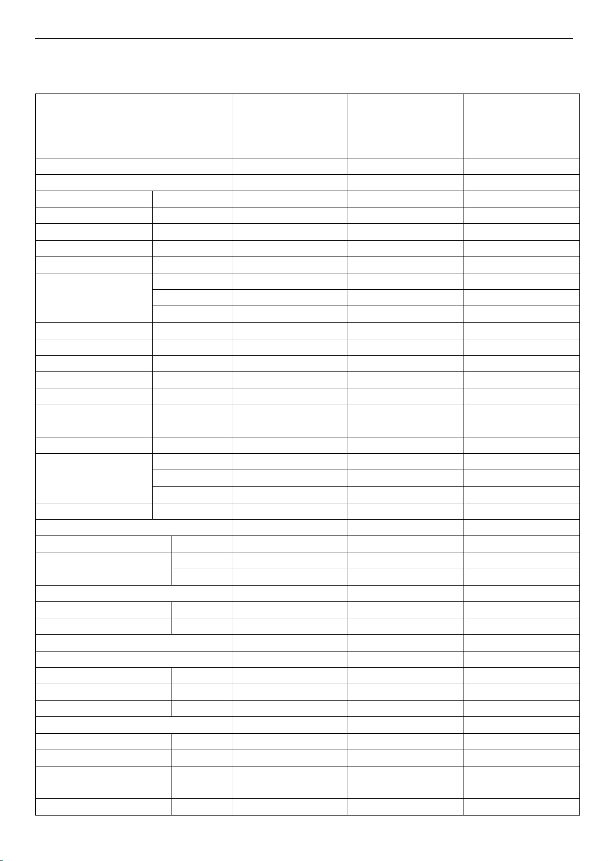
2. Product Specifications
ABXEM4H4S09/ABX
Model No.
Type
Ratings
Cooling Capacity W
Heating Capacity W
Rated Input-Cooling W
Rated Input-Heating W
Moisture Removal L/h
High m3/h
Air Circulation
EER for Cooling W/W
COP for Heating W/W
Energy Class Cooling
Energy Class Heating
Refrigerant
Refrigerant charge
volume (5M)
Additional ref. Volume g
Indoor Unit Noise Level
Outdoor Unit Noise Level dB (A)
Power Supply
Voltage, Frequency, Phase V
Rated Current
System pressures in cooling rated conditions
Max suction pressure MPa
Max discharge pressure MPa
System
Compressor
Compressor type
Compressor Model No.
Compressor MFG
Connecting Pipe Diameter
Liquid Pipe inch
Gas Pipe inch
Cooling Setting Temperature
Range
Heating Setting Temperature
Mid m3/h
Low m3/h
g
High(dB (A))
Mid(dB (A))
Low(dB (A))
Cooling (A)
Heating (A)
℃
℃
CI4H4S09
T1, H/P, INVERTER T1, HP, INVERTER T1, HP, INVERTER
2600 3517
2750 3810
655 920
720 1120
0.9 1.2
580
/
/
22.50 3.82
10.70 3.40
SEER20
SEER20
R410A R410A
950 1160
20 20
39 39
32
29
53 53
220-240V~,60Hz,1P 230/208V~,60Hz,1P 230/208V~,60Hz,1P
2.9 4.1
3.2 5.0
1.6 1.6
4.15 4.15
Rotary Rotary
ASD088RKQA6JT6 ASN108D32UFZ
HITACHI
1/4 1/4
3/8 3/8
16-30
16-30
ABXEM4H4S12/ABX
CI4H4S12
620
/
/
SEER22.0
HSPF10.5
GMCC
16-30
16-30
ABXEM4H4S18/ABX
CI4H4S18
5275
5569
1385
1595
1100
21.5
10.0
R410A
1550
20
45
41
37
6.3
7.2
1.65
3.79
Rotary
ATM150D43UFZ
GMCC
1/4
1/2
16-30
16-30
/
/
/
/
/
55
5
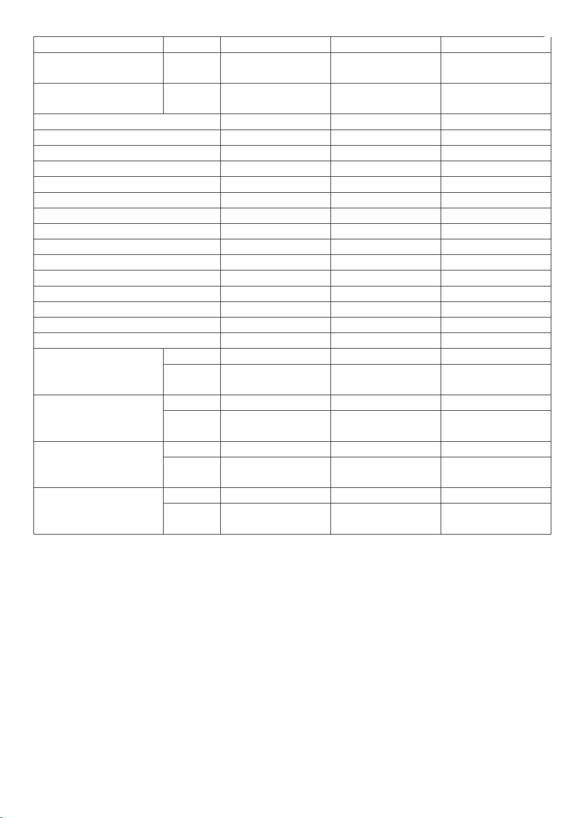
Range
Cooling Operating
Temperature Range
Heating Operating
Temperature Range
Features
Display on Front Panel
LCD Wireless Remote Controller
Removable and washable Panel
Washable PP Filter
24 Hours Timer
3 Speed and Auto Indoor Fan Control
Vertical Auto Swing Louver
Manual Adjustable Horizontal Swing Louver
Sleep Operation
Smart Function
Super Function
Auto Restart
Dimmer
Other
Net Dimensions
WxHxD (mm)
Net Weight (Kg)
Packing Dimensions WxHxD
(mm)
Gross Weight (Kg)
℃
℃
Indoor Unit
Outdoor
Unit
Indoor Unit
Outdoor
Unit
Indoor Unit
Outdoor
Unit
Indoor Unit
Outdoor
Unit
16-43 -15-46
-15--46 -15-32
LED LED LED
Yes Ye s Yes
Yes Ye s Yes
Yes Ye s Yes
Yes Ye s Yes
Yes Ye s Yes
Yes Ye s Yes
Yes Ye s Yes
Yes Ye s Yes
Yes Ye s Yes
Yes Ye s Yes
Yes Ye s Yes
Yes Ye s Yes
/ /
715×240×486 810×585×280
/ /
27 33
/ /
830×315×530
940×630×385
/ /
29.5 36
-15-24
860×650×310
995×720×420
6
21-46
/
/
45
/
/
49
ABXEM4H4S24/ABXCI4H4S2
Model No.
Type
Ratings
Cooling Capacity W
Heating Capacity W
Rated Input-Cooling W
Rated Input-Heating W
Moisture Removal L/h
High m3/h
Air Circulation
EER for Cooling W/W
COP for Heating W/W
Energy Class Cooling
Energy Class Heating
Refrigerant
Refrigerant charge
volume (5M)
Additional ref. Volume g
Indoor Unit Noise Level
Outdoor Unit Noise Level dB (A)
Power Supply
Voltage, Frequency, Phase V
Rated Current
System pressures in cooling rated conditions
Max suction pressure MPa
Max discharge pressure MPa
System
Compressor
Compressor type
Compressor Model No.
Compressor MFG
Connecting Pipe Diameter
Liquid Pipe inch
Gas Pipe inch
Mid m3/h
Low m3/h
g
High(dB (A))
Mid(dB (A))
Low(dB (A))
Cooling (A)
Heating (A)
4
T1, HP, INVERTER
6850
7620
1874
2500
2.4
1200
/
/
3.66
3.05
SEER21
HSPF10.5
R410A
2150
30
47
/
/
58
230V~,60Hz,1P
8.3
11.1
1.6
4.15
Rotary
ATF135D22UMT
GMCC
3/8
5/8
7
Cooling Setting Temperature
Range
Heating Setting Temperature
Range
Cooling Operating
Temperature Range
Heating Operating
Temperature Range
Features
Display on Front Panel
LCD Wireless Remote Controller
Removable and washable Panel
Washable PP Filter
24 Hours Timer
3 Speed and Auto Indoor Fan Control
Vertical Auto Swing Louver
Manual Adjustable Horizontal Swing Louver
Sleep Operation
Smart Function
Super Function
Auto Restart
Dimmer
Other
Net Dimensions
WxHxD (mm)
Net Weight (Kg)
Packing Dimensions WxHxD
(mm)
Gross Weight (Kg)
℃
℃
℃
℃
Indoor Unit
Outdoor
Unit
Indoor Unit
Outdoor
Unit
Indoor Unit
Outdoor
Unit
Indoor Unit
Outdoor
Unit
18-30
18-30
-15~46℃
-20~24℃
LED
Yes
Yes
Yes
Yes
Yes
Yes
Yes
Yes
Yes
Yes
Yes
Yes
/
885×365×793
/
61
/
1050×500×890
/
69
8
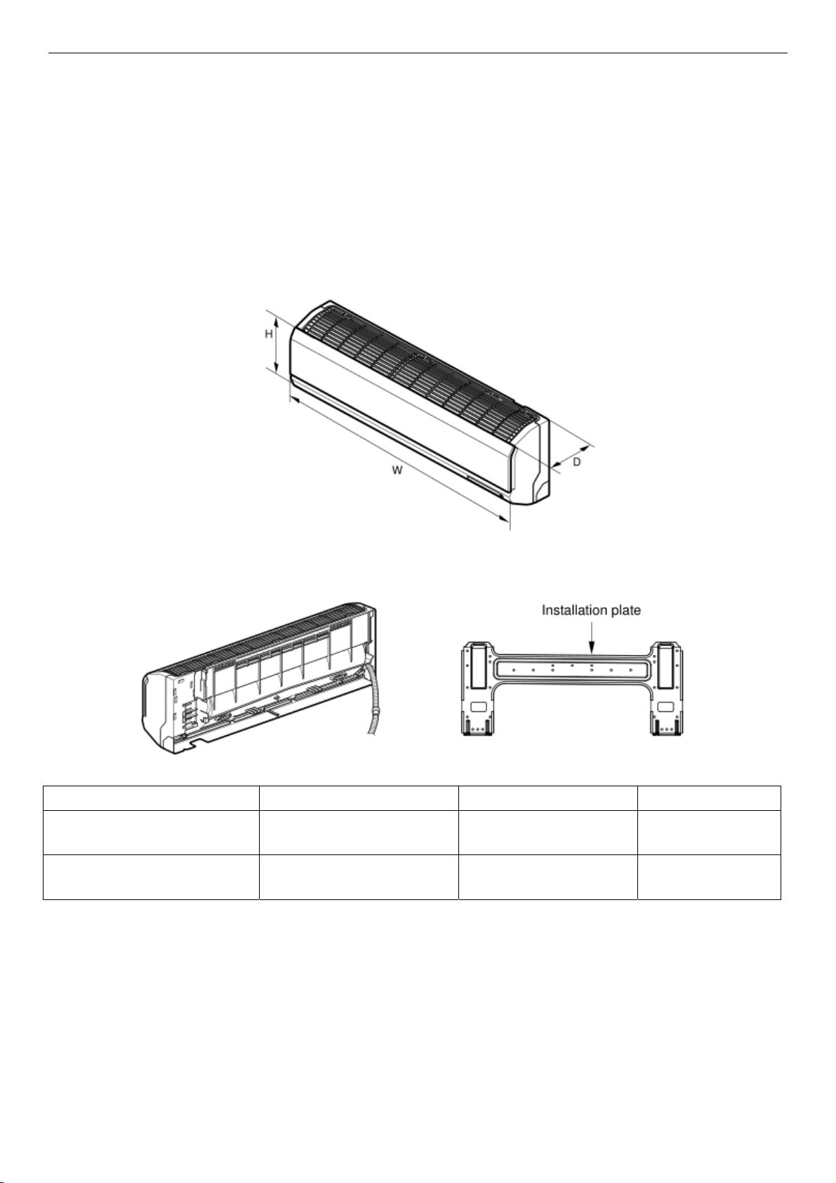
3. Product Picture and Drawing
3-1. Product dimensions
Indoor units:
Model W (mm) H (mm) D (mm)
ABXEM4H4S09
ABXEM4H4S12
ABXEM4H4S18
ABXEM4H4S24
Outdoor units:
850 270 206
1131 315 228
9
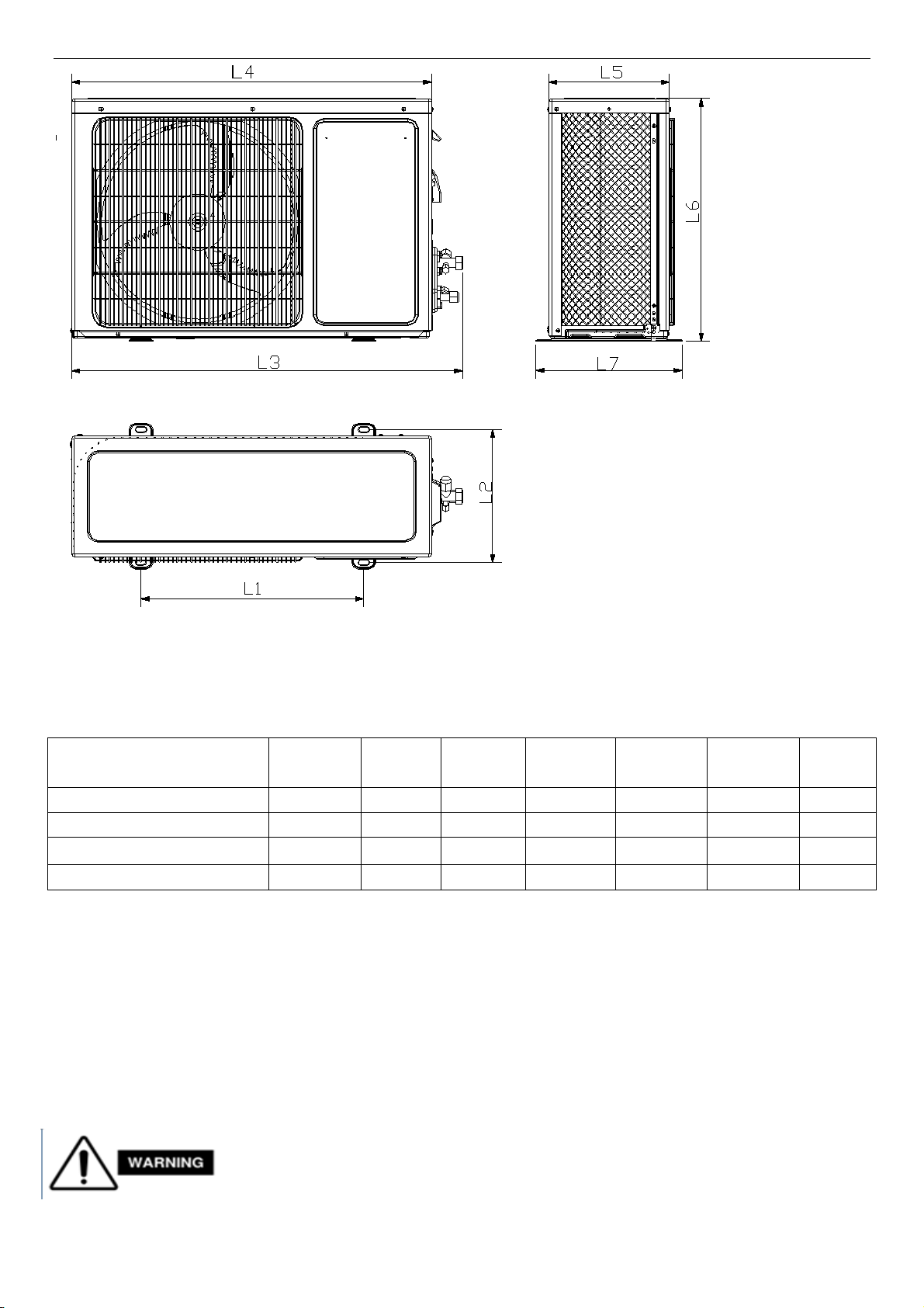
Model L1
ABXCI4H4S09
ABXCI4H4S12
ABXCI4H4S18
ABXCI4H4S24
(mm)
L2
(mm)
L3
(mm)
L4
(mm)
L5
(mm)
L6
(mm)
L7
(mm)
443 264 776 715 240 486 290
510 320 886 810 280 585 330
542 341 935 878 310 667 368
662 390 959 884 365.5 793 414
4. Installation Instruction
To prevent abnormal heat generation and the possibility of fire, do not place
obstacles, enclosures and grilles in front of or surrounding the air conditioner in a
way that may clock air flow. And, more than 1 meter away from any antenna or
10
power lines or connecting wires used for TV, radio, telephone, security system, or intercom. Electrical
noise from any of these sources may affect operation.
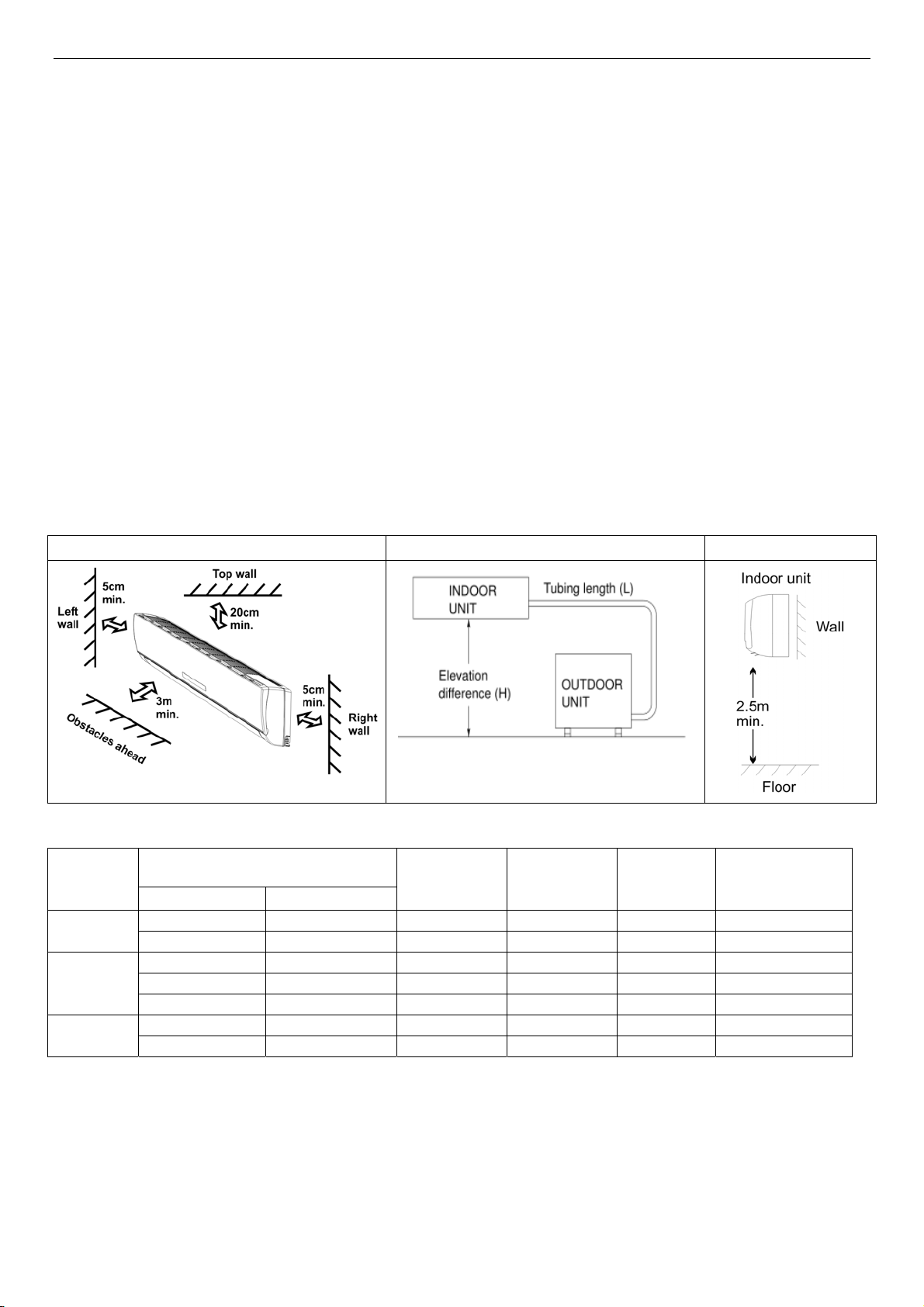
4-1. Installation Place and Condition
Indoor unit
Avoid:
△ direct sunlight.
△ nearby heat sources that may affect performance of the unit.
△ areas where leakage of flammable gas may be expected.
△ places where large amounts of oil mist exist.
Do:
△ Select an appropriate position from which every corner of the room can be uniformly cooled.
△ Select a location that will hold the weight of the unit.
△ Select a location where tubing and drain hose have the shortest run to the outside. (See a)
△ Allow room for operation and maintenance as well as unrestricted air flow around the unit. (See b)
△ Install the unit within the maximum elevation difference (H) above or below the outdoor unit and
within a total tubing length (L) from the outdoor unit as detailed (See table 1 and c)
a b c
table 1
Capacity
(Btu/h)
5k~14k
18k~28k
30k~38k
* If total tubing length becomes 7.5 to 15 m (max.), charge additional refrigerant as the table1 for
reference. And no additional compressor oil is necessary.
3/8"(Ø9.52) 1/4"(Ø6.35) 7.5 10 15 20
1/2"(Ø12.7) 1/4"(Ø6.35) 7.5 10 15 20
1/2"(Ø12.7) 1/4"(Ø6.35) 7.5 10 15 20
5/8"(Ø15.88) 1/4"(Ø6.35) 7.5 10 15 20
5/8"(Ø15.88) 3/8"(Ø9.52) 7.5 10 15 30
5/8"(Ø15.88) 3/8"(Ø9.52) 7.5 10 15 30
3/4"(Ø19.05) 3/8"(Ø9.52) 7.5 10 15 50
Pipe Size
GAS LIQUID
Standard
Length
(m)
Max.
Elevation
B (m)
Max.
Length
A (m)
Additional
Refrigerant
(g/m)
Outdoor unit
Avoid:
△ Heat sources, exhaust fans, etc.
△ Damp, humid or uneven locations.
11
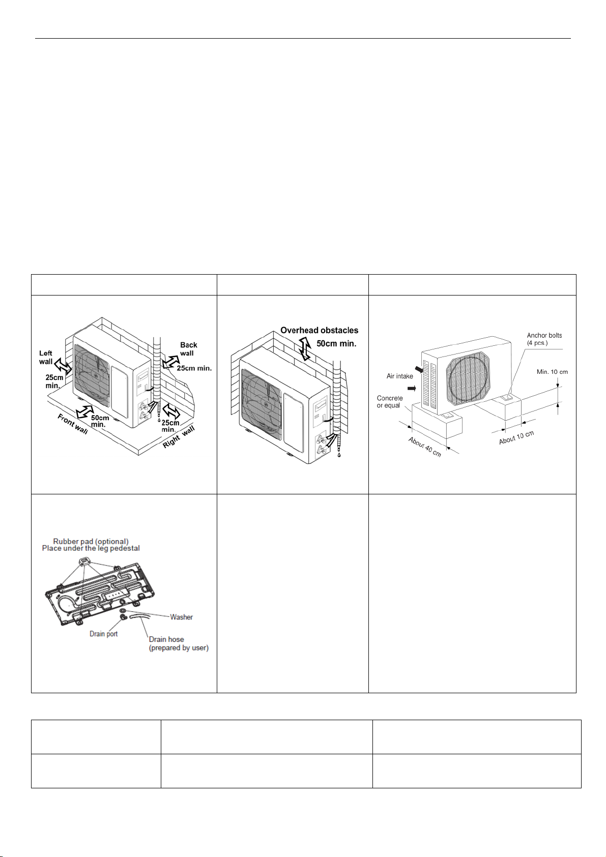
DO:
△ Choose a place as cool as possible.
△ Choose a place that is well ventilated.
△ Allow enough room around the unit for air intake or exhaust and possible maintenance. (see a1,
b1 & c1)
△ Provide a solid base (level concrete pad, concrete block, 10 × 40 cm beams or equal), a minimum
of 10 cm above ground level to reduce humidity and protect the unit against possible water damage
and decreased service life.
△ If the installation bag has rubber pads, it is strongly recommended for use to reduce vibration and
noise.
△ Use lug bolts or equal to bolt down unit, reducing vibration and noise.
a1 b1 c1
Recommended Wire Diameter:
Capacity size Wire Diameter(mm2) Fuse or Circuit Breaker Capacity
5K~12k 1.0(Power wire)/1.0(Connect wire) 3.15A or 5A(indoor)/15A(outdoor)
12

18k 2.5(Power wire)/1.5(Connect wire) 3.15A or 5A(indoor)/20A(outdoor)
22K~30K 2.5(Power wire)/2.5(Connect wire) 3.15A or 5A(indoor)/30A(outdoor)
13
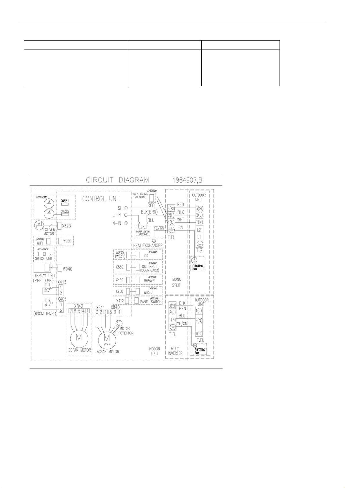
4-2. Electric Wiring Diagram
Model Indoor Unit DIAGRAM Outdoor Unit DIAGRAM
ABXEM4H4S09/ABXCI4H4S09
ABXEM4H4S12/ABXCI4H4S12
ABXEM4H4S18/ABXCI4H4S18
ABXEM4H4S24/ABXCI4H4S24
Indoor:
1984907
1984907 1854707
14
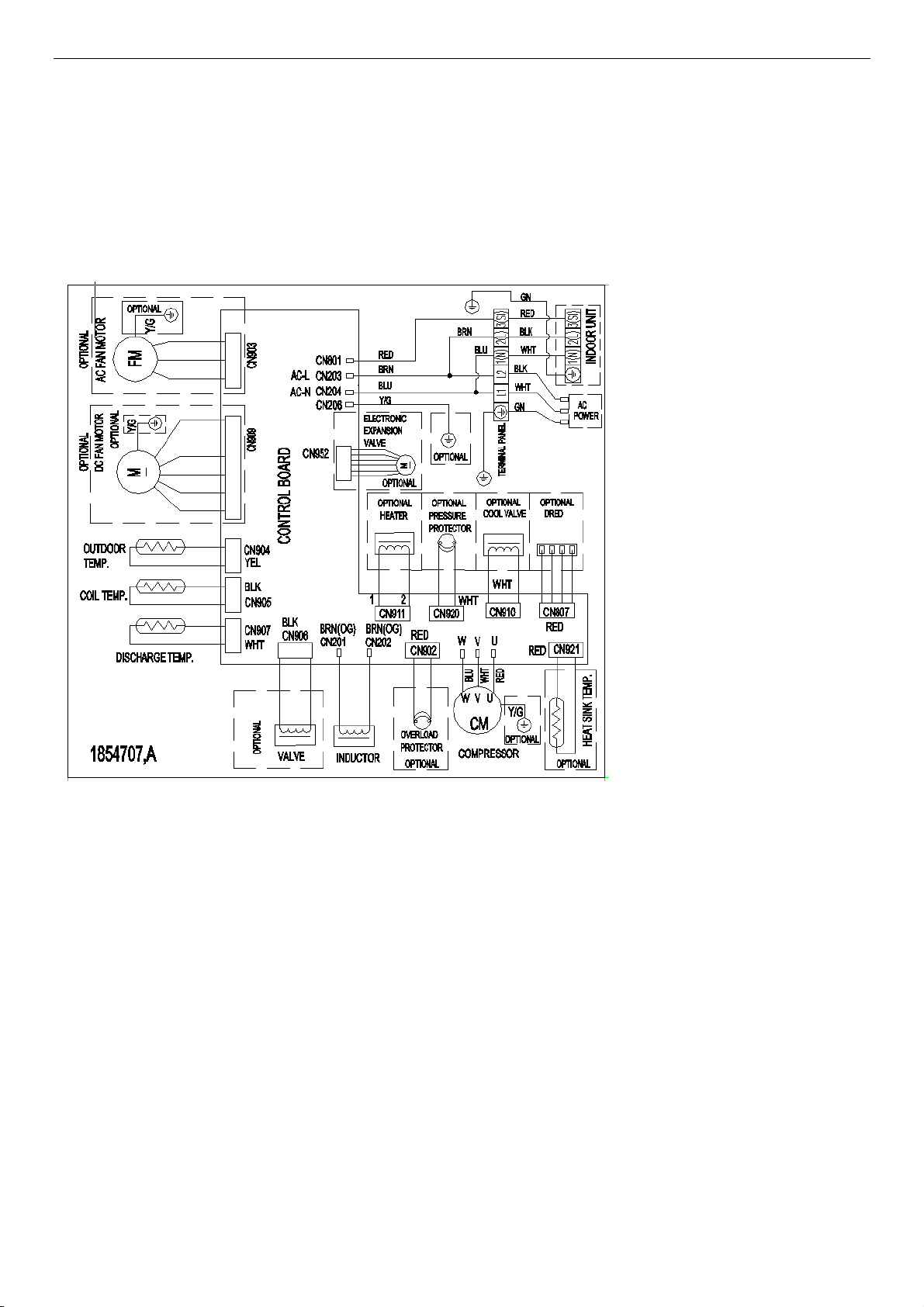
Outdoor:
1854707
15
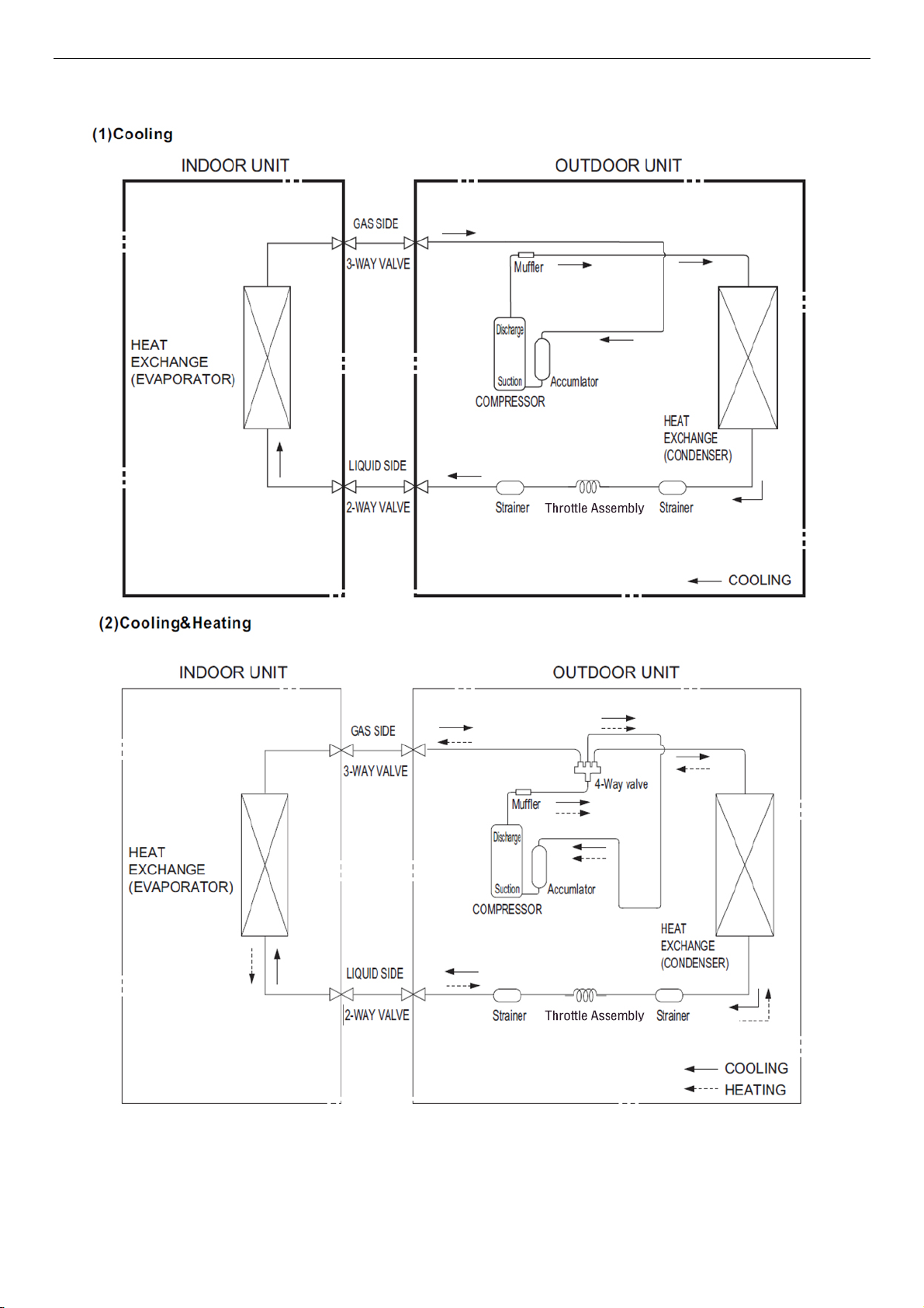
4-3. Refrigerant Flow System
NOTE: In different models, the throttle assembly may be Capillary or Electronic expansion valve.
16
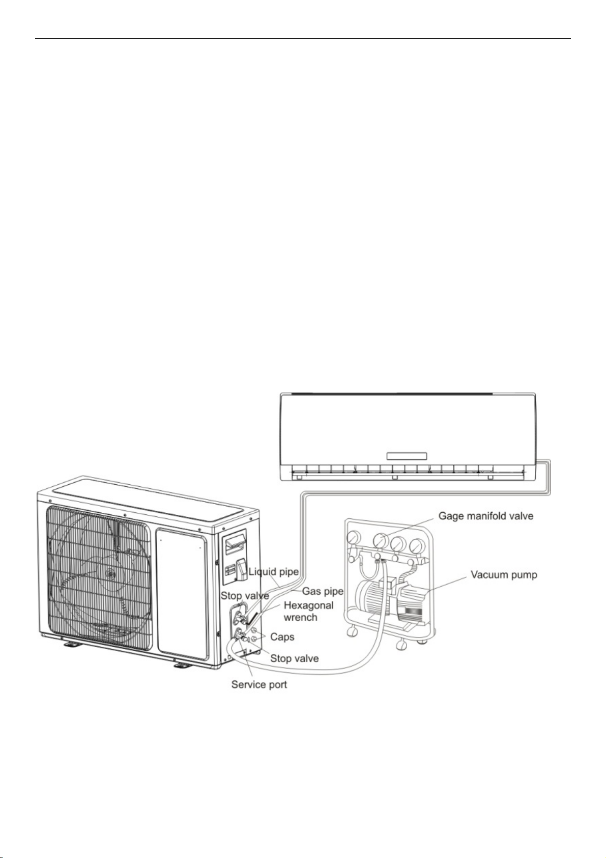
4-4. Air Purging and Leakage Test
1. Connect charging hose of manifold valve to charge end of low pressure valve (both high/low
pressure valves must be tightly shut).
2. Connect joint of charging hose to vacuum pump.
3. Fully open the handle of Lo manifold valve.
4. Open the vacuum pump to evacuate. At the beginning, slightly loosen joint nut of low pressure
valve to check if there is air coming inside. (If noise of vacuum pump has been changed, the reading
of multimeter is 0) Then tighten the nut.
5. Keep evacuating for more than 15mins and make sure the reading of multi-meter is -1.0 X10⁵ pa
(-76cmHg).
6. Check the vacuum with the gage manifold valve, then close the gage manifold valve, and stop the
vacuum pump.
7. Leave it for one or two minutes. Make sure the pointer of the gage manifold valve remains in the
same position.
8. Remove the gage manifold valve quickly from the service port of the stop valve.
After refrigerant pipes are connected and evacuated, fully open all stop valves on gas and liquid pipe
sides.
9. Opening without fully opening lowers the performance and cause dangerous.
10. Tighten the cap to the service port to obtain the initial status.
11. Retighten the cap
12. Leak test
17

4-5. Test Running
△ Check after Installation
Items to be checked Possible malfunction
Has it been fixed firmly? The unit may drop, shake or emit noise.
Have you done the refrigerant leakage test?
Is heat insulation sufficient? It may cause condensation and dripping.
Is water drainage satisfactory? It may cause condensation and dripping.
Is the voltage in accordance with the rated
voltage marked on the nameplate?
Is the electric wiring and piping connection
installed correctly and securely?
Has the unit been connected to a secure earth
connection?
Is the power cord specified?
Are the inlet and outlet openings blocked?
Is the length of connection pipes and
refrigerant capacity been recorded?
It may cause insufficient
cooling(heating)capacity
It may cause electric malfunction or damage the
product.
It may cause electric malfunction or damage the
part.
It may cause electrical leakage.
It may cause electric malfunction or damage the
part.
It may cause insufficient
cooling(heating)capacity.
The refrigerant capacity is not accurate.
△Operation Test
1. Before Operation Test
(1)Do not switch on power before installation is finished completely.
(2)Electric wiring must be connected correctly and securely.
(3)Cut-off valves of the connection pipes should be opened.
(4)All the impurities such as scraps and thrums must be cleared from the unit.
2. Operation Test Method
(1)Switch on power and press “ON/OFF” button on the remote controller to start the operation.
(2)Press MODE button to select the COOL, HEAT (Cooling only unit is not available), FAN to check
whether the operation is normal or not.
18

5. Function Operation
5-1. Operation Range (cooling and heating)
North America SEER 20 Model(9k-24k)&SEER16 Model(30k、36k):
Temperature Indoor Air Intake Temp. Outdoor Air Intake Temp
COOLING
Maximum
Minimum
Maximum
HEATING
Minimum /
North America SEER 28 Model:
Temperature Indoor Air Intake Temp. Outdoor Air Intake Temp
Maximum
COOLING
Minimum
Maximum
HEATING
Minimum /
30℃(86°F) 46 ℃(115°F)
16℃ (61°F) -15℃(5°F)
30℃ (86°F) 24℃ (75°F)
-15℃ (5°F)
30℃(86°F) 46 ℃(115°F)
16℃ (61°F) -18℃(-0.4°F)
30℃ (86°F) 24℃ (75°F)
-25℃ (5°F)
Note: The parameters for generic only, the exact value please refer to the product
specification.
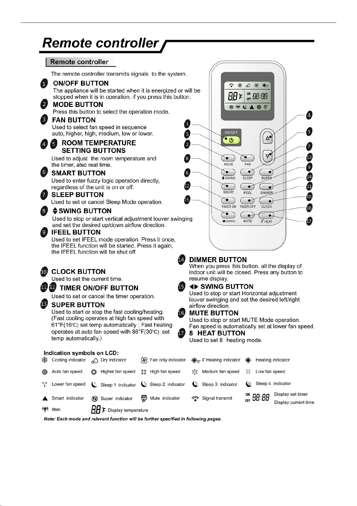
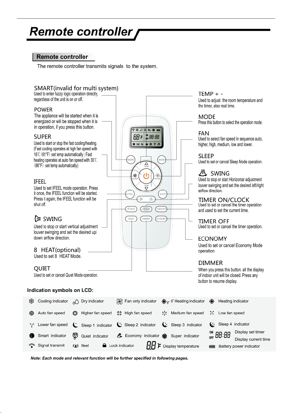
5-2. Remote Controller Operation & Function
△Remote Controller Instruction
J1-72
19
L1-04
20
Function Instruction
△
1.Major general technical parameters
21
 Loading...