

Air Comm Systems ACS 1278-300 Operations and Installation Manual
Air Comm Systems, Inc.
AirComm
Airborne Audio Products
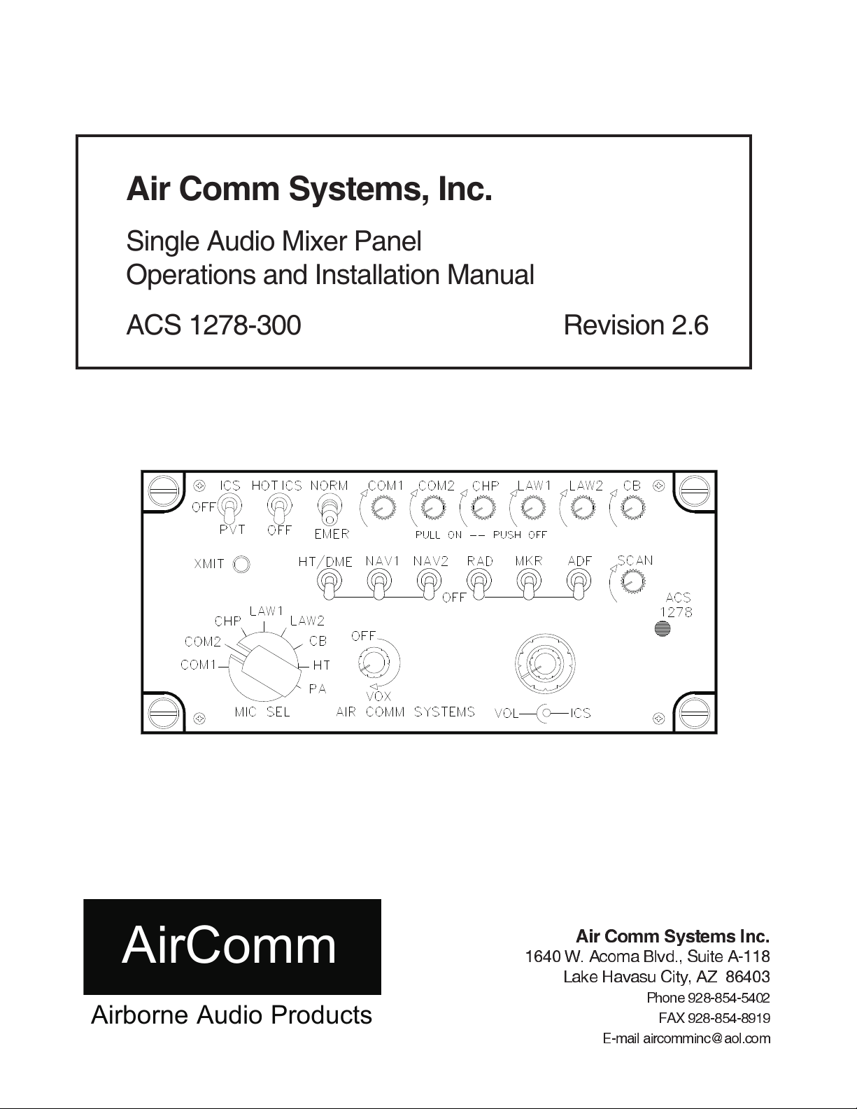
Single Audio Mixer Panel
Operations and Installation Manual
ACS 1278-300 Revision 2.6
Air Comm Systems Inc.
1640 W. Acoma Blvd., Suite A-118
Lake Havasu City, AZ 86403
Phone928-854-5402
FAX 928-854-8919
E-mail aircomminc@aol.com

ACS 1278-300 Operations and Installation Manual
Table of Contents
Installation
n
Physical and Operating Specifications Page 3
Physical Dimensions Page 4
InterfaceSchematic Page 5
Operation
n
Front Panel Controls Page 6-8
Front Panel ControlsPictorial
Addendum
n
Page 9
Instructions for Continued Airworthiness Page 10
n
Warranty Information
Warranty Information Page 11
n
Supplemental Information
Product Schematics ________
Air Comm Systems, Inc. Page 2
ACS 1278-300 Operations and Installation Manual
Physical and Operating Specifications
Physical Specifications
n
SIZE:
CONTROLS:
dimmer bus for adjustment. Amber transmit light indicates when unit is in transmit mode.
Operating Specifications
n
INPUTS:
DUTY CYCLE:
MAXIMUM OPERATING ALTITUDE:
OPERATING TEMPERATURE RANGE:
5.75 in. (14.61cm) W
2.62 in.( 6.67 cm) H
6.78 in.(17.22 cm) D
Panel mounted - transmit = rotary switch, audio inputs = potentiometer,
ILLUMINATION:
13 selectable receive audio inputs and up to 11 transmit selections.
toggle switch, VOX= on/off volume potentiometer,
ICS and headphone volume control = dual potentiometer
Edge lit front panel per MIL-P-7738E, type 5. Capable of connection to
Continuous
WEIGHT:
MOUNTING:
POWER REQUIREMENTS:
22,000 ft.
-40 C to +85 C (operating)
-65 C to +125 C (storage)
2.20 lb. (.99 kg)
Dzus rail mount (4)
28V DC +/- 10%
CURRENT DRAIN:
AUDIO OUTPUT:
FREQUENCY RESPONSE:
ICS INPUT IMPEDANCE:
RECEIVER INPUT IMPEDANCE:
INPUT ISOLATION:
AUDIO MUTING:
MIKE SENSITIVITY:
DISTORTION:
70 mA at 28V (standby) - 500mA at 28V (max. signal)
Minimum 250 mW into 600 ohms
Within 6 db - 300-3000Hz
600 ohms
600 ohms - matched to receiver
Not less than 50 db between inputs
Not less than 40 db during transmit/ICS (optional)
300 mV for rated output
Less than 10% at 1000 Hz for maximum output
Air Comm Systems, Inc. Page 3
ACS 1278-300 Operations and Installation Manual
Physical Dimensions
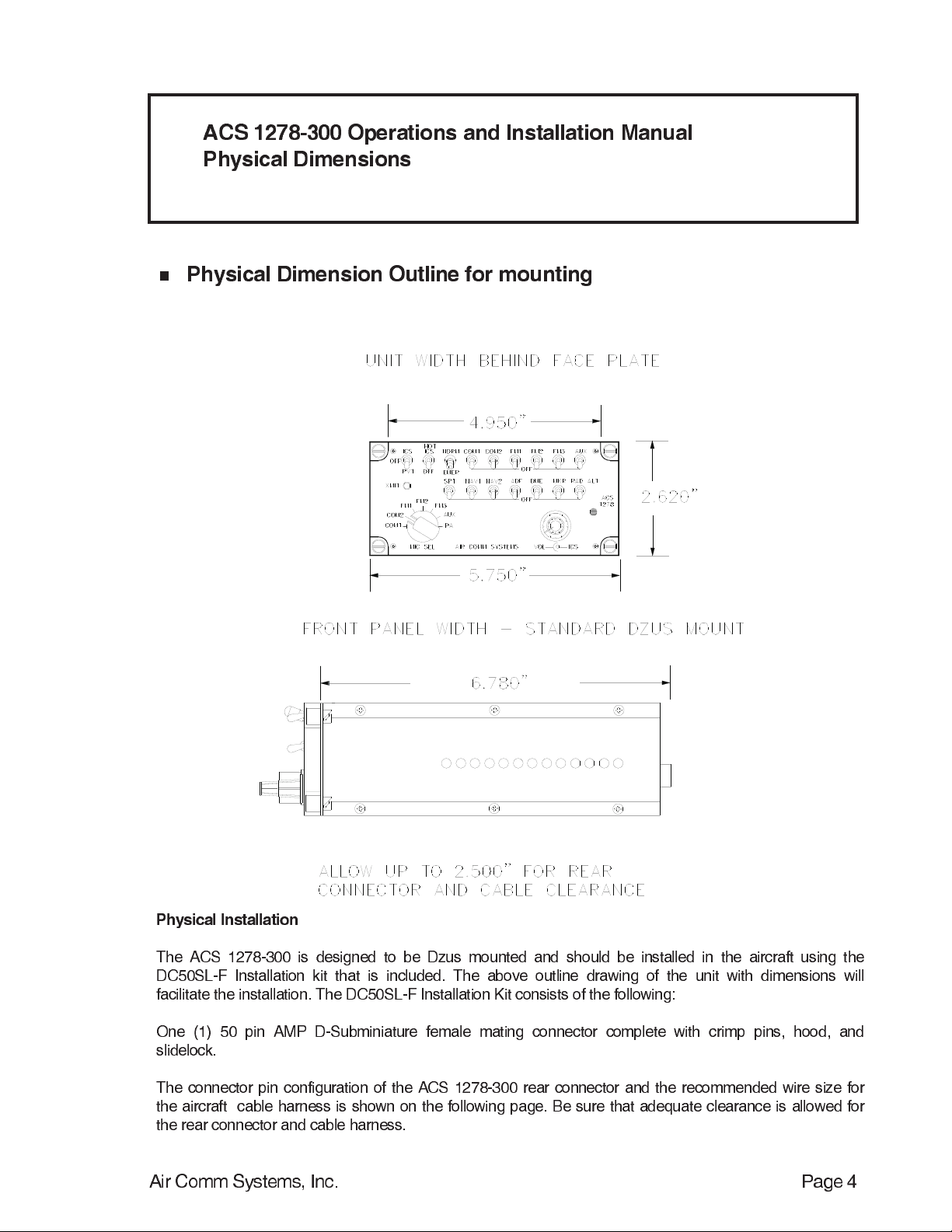
Physical Dimension Outline for mounting
n
Physical Installation
The ACS 1278-300 is designed to be Dzus mounted and should be installed in the aircraft using the
DC50SL-F Installation kit that is included. The above outline drawing of the unit with dimensions will
facilitate the installation. The DC50SL-F Installation Kit consists of the following:
One (1) 50 pin AMP D-Subminiature female mating connector complete with crimp pins, hood, and
slidelock.
The connector pin configuration of the ACS 1278-300 rear connector and the recommended wire size for
the aircraft cable harness is shown on the following page. Be sure that adequate clearance is allowed for
the rear connector and cable harness.
Air Comm Systems, Inc. Page 4
 Loading...