

Page 1
MODEL NO. 6265
1.0 HP Angle Die Grinder
Page 2
Important Warnings - Die Grinders
1. Only use mounted grinding stones or mounted carbide burrs that meet ANSI standards, ISO standards or both.
2. Never adjust the die grinder, adjust the collets or change the mounted stones or mounted burrs unless the air supply and air hose is
disconnected from the die grinder.
3. Only personnel trained in the correct methods to adjust collets and change mounted stones and mounted burrs should conduct these
operations.
4. Always ensure that you are aware of the direction of the sparks being created by the grinding operation and ensure that the sparks are
not directed toward the operator or other persons in the area.
5.
6. Only use mounted stones or carbide burrs that have the correct spindle diameter that matches the original collet size provided by the die
grinder manufacturer.
7. Particular care must be taken not to use metric size mounted stones and mounted burrs with die grinders that have imperial size collets,
or use imperial mounted stones and mounted burrs with die grinders that have metric collets.
SPECIFICATIONS
Model No.
6265 18,000 1.0 1/4 5:1 Bevel Gears Rear 9.5 1.8 4.2 3/8 1/4
Free Speed
(RPM)
Motor
(HP)
Collet / Spindle
Size (in.)
Gears Exhaust
Length
(in.)
Weight
(lbs.)
Air
Cons.
(CFM)
Rec.
Hose
Size (in.)
Air Inlet
(in.) NPT/
BSP
Air Supply
Tools of this class operate on a wide range of air pressure. It is recommended that air pressure of these tools measures 90 PSI at the tool while running free. Higher
pressure and unclean air will shorten the tool’s life because of faster wear and may create a hazardous condition and void the warranty. Water in the air line will
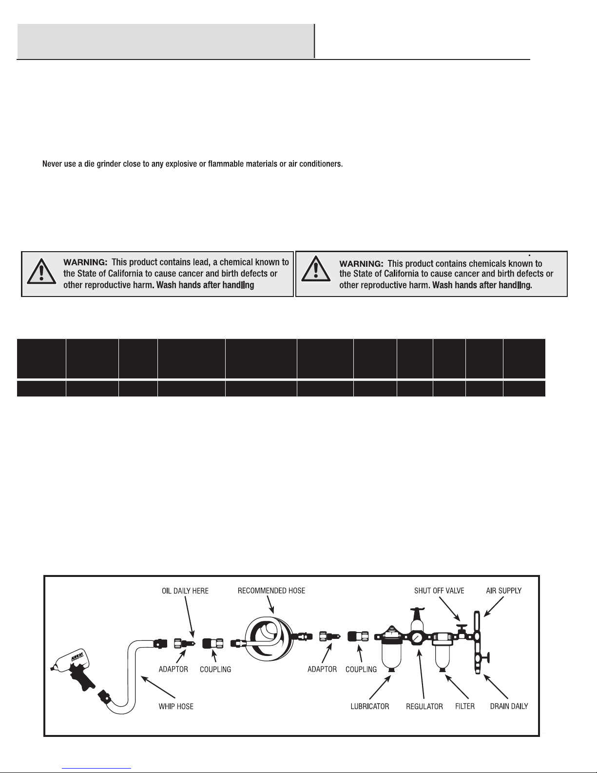
cause damage to the tool. Drain the air tank daily. Clean the air inlet lter screen on at least a weekly schedule. The recommended hookup procedure can be viewed
in the illustration below. The air inlet, used for connecting air supply, has standard 1/4” NPT / BSP. Line pressure should be increased to compensate for unusually
long air hoses (over 25 feet). Minimum hose diameter should be 3/8” I.D. and ttings should have the same inside dimensions.
Page 3
MODEL N0. 6265
1.0 HP Angle Die Grinder
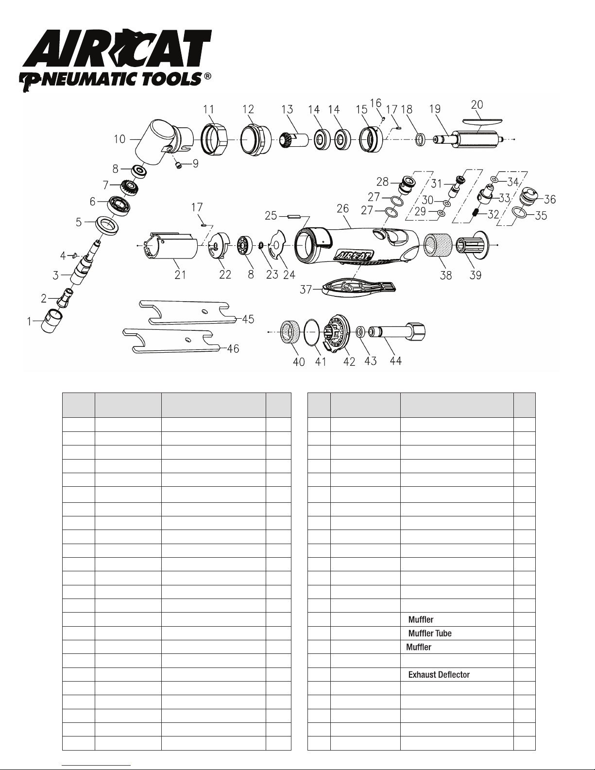
Exploded View & Parts List
Ref #Part Number Description Qty Ref #Part Number Description Qty.
1 501A-001 Collect Nut 1 24 218F-045-C Rear Gasket 1
2 511-002 Collect (6mm) 1 25 216-037 Seal Lump 1
511-002B Collect (1/4”) 26 541F-025 Motor Housing 1
3 541FA-003 Spindle 1 27 00-41121 O-Ring 2
4 00-3701 Key 1 28 218F-026 Bushing 1
5 541FA-002 Angle Housing Nut 1 29 00-41133 O-Ring 1
6 00-2396 Ball Bearing 1 30 00-41132 O-Ring 1
7 541FA-009 Spiral Bevel Gear 1 31 218F-027 Valve Stem 1
8 00-2323 Ball Bearing 2 32 218F-029 Spring 1
9 00-4605 Grease Fitting 1 33 551F-038 Regulator 1
10 541FA-004 Angle Housing 1 34 00-4102 O-Ring 1
11 541FA-005 Nut 1 35 00-41134 O-Ring 1
12 541FA-006 Clamp Nut 1 36 551F-030 Valve Plug 1
13 541FA-008 Spiral Bevel Gear 1 37 218F-043 Throttle Lever 1
14 00-2314 Ball Bearing 2 38 541F-038
15 541FA-019 Front End Plate 1 39 218F-039
16 00-3328 Spring Pin 1 40 541F-038B
17 00-3325 Spring Pin 2 41 00-4159 O-Ring 1
18 511-006 Spacer 1 42 218F-042
19 541FA-020 Rotor 1 43 218F-050 Bushing 1
20 541F-021 Rotor Blade 4 44 218F-034A Air Inlet (1/4” PF) 1
21 541F-022 Cylinder 1 218F-034C Air Inlet (1/4” NPT)
22 218F-023 Rear End Plate 1 45 511-007 Double Ended Wrench 1
23 00-3505 Snap Ring 1 46 411-034 Double Ended Wrench 1
1
1
1
1
Page 4
 Loading...