

OPERATING MANUAL
VACUUM/PRESSURE STATION
MODEL NO. 420-3901 (115V AC)
MODEL NO. 420-3902 (230V AC)
A-1299-5105
Edition 02
Thermo Fisher Scientific
1-800-637-3739 (U.S. and Canada only)
11 (847) 381-7050 (Outside U.S.) • (847) 381-7050 (Local)
www.thermo.com • bar.barnant@thermofisher.com

2

TABLE OF CONTENTS
Title Page
SAFETY PRECAUTIONS . . . . . . . . . . . . . . . . . . . . . . . . . . . . . . . . . . . . . 4
DESCRIPTION . . . . . . . . . . . . . . . . . . . . . . . . . . . . . . . . . . . . . . . . . . . . . 5
OPERATING INSTRUCTIONS . . . . . . . . . . . . . . . . . . . . . . . . . . . . . . . . . 6
Grounding Instructions . . . . . . . . . . . . . . . . . . . . . . . . . . . . . . . . . . 6
SPECIFICATIONS . . . . . . . . . . . . . . . . . . . . . . . . . . . . . . . . . . . . . . . . . .10
MAINTENANCE . . . . . . . . . . . . . . . . . . . . . . . . . . . . . . . . . . . . . . . . . . . .11
REPLACEMENT PARTS LIST . . . . . . . . . . . . . . . . . . . . . . . . . . . . . . . . .14
PUMP HEAD REPLACEMENT PARTS LIST . . . . . . . . . . . . . . . . . . . . .14
SPECIAL APPLICATIONS . . . . . . . . . . . . . . . . . . . . . . . . . . . . . . . . . . . .14
NOTE . . . . . . . . . . . . . . . . . . . . . . . . . . . . . . . . . . . . . . . . . . . . . . . . . . .14
WARRANTY . . . . . . . . . . . . . . . . . . . . . . . . . . . . . . . . . . . . . . . . . . . . . . .15
PRODUCT RETURN . . . . . . . . . . . . . . . . . . . . . . . . . . . . . . . . . . . . . . . .15
TECHNICAL ASSISTANCE . . . . . . . . . . . . . . . . . . . . . . . . . . . . . . . . . . .15
FLUOREL - Reg TM Minnesota Mining and Manufacturing Company
VAL OX - Reg TM General Electric Co.
VITON - Reg TM E.I. DuPont de Nemours and Company
Trademarks bearing the ® symbol in this publication
are registered in the U.S. and in other countries.
3

SAFETY PRECAUTIONS
DANGER: Improper use of grounding plug can result in a risk of electric
shock.
DANGER: Unplug power cord before any cleaning operation is started.
WARNING: Gas under pressure should not be used for supply as a haz-
ardous bursting condition could develop in the pump head.
Use only gases contained at atmospheric pressure.
CAUTION: Do not operate pump when pressure ports of both heads are
in a blocked condition.
4

DESCRIPTION
The Vacuum/Pressure Station is designed to provide a convenient,
portable source of regulated vacuum and/or pressure for bench-top laboratory or commercial use. Each function is regulated independently by
clearly identified valves and the easy-to-read compound function gauge
eliminates the need for an elaborate plumbing network. The convoluted
diaphragm and the unique head cavity of the pump are designed to provide
extended diaphragm life by minimizing stress, wear and heat buildup. This
has been done while ensuring and optimizing pressure and vacuum characteristics. The brushless pump motor is totally enclosed, thermally protected and has sealed ball bearings. No regular maintenance of the motor
is required. A six foot long, three conductor power supply cord is supplied
with the unit and the 115V AC motor is a U.L. recognized component.
Figure 1 shows the typical flow characteristics of the 115V station as related to pressure and vacuum. The corresponding flow data for the 230V station are 5/6 of the values shown in Figure 1. Also note that, even though
model 420-3902 is designed for 50 Hz applications, it can be run on 230V
AC, 60 Hz line current. In this condition, the flow data will equal that of the
420-3901 station but available torque will decrease. All units are intended
to be started without load (both ports open to atmosphere). If either a vacuum or pressure exists, the pump may not start.
Always consider material compatibility before running any service through
the Vacuum/Pressure Station.
The Materials in contact with the service are as follows:
1) Pump — VALOX
®
(polyester), FLUOREL®and VITON®.
2) Manifold chamber and fittings — PVC, silicone, linear polyethylene
and stainless steel 303.
3) Pressure/Vacuum Gauge — Bronze tubing and brass socket.
5

OPERATING INSTRUCTIONS
The pump supplied with the Vacuum/Pressure Station must always be
plugged into a grounded outlet. Both models are supplied complete with a
grounded plug and an on-off rocker switch.
Grounding Instructions
This product should be grounded. In the event of an electrical short circuit,
grounding reduces the risk of electric shock by providing an escape wire
for the electric current. This product is equipped with a cord having a
grounding wire with an appropriate grounding plug. The plug must be
plugged into an outlet that is properly installed and grounded in accordance
with all local codes and ordinances.
DANGER: Improper use of grounding plug can result in a risk of electric
shock.
6
FIGURE 1

If repair or replacement of the cord or plug is necessary, do not connect the
grounding wire to either flat blade terminal. The wire with insulation having
an outer surface that is green with or without yellow stripes is the grounding wire. Check with a qualified electrician or serviceman if the grounding
instructions are not completely understood, or if in doubt as to whether the
product is properly grounded. Do not modify the plug provided; if it will not
fit the outlet, have the proper outlet installed by a qualified electrician.
This product is for use on a nominal 120 volt circuit for Model 420-3901 and
a 230 volt, 50 cycle circuit for Model 420-3902. Model 42 0-3901 has a
grounding plug that looks like the adapter illustrated in Figure 2(A). A temporary adapter, which looks like the adapter illustrated in Figure 2(B) and
(C) may be used to connect this plug to a 2-pole receptacle as shown in
Figure 2(B) if a properly grounded outlet is not available. The temporary
adapter should be used only until a properly grounded outlet, Figure 2(A),
can be installed by a qualified electrician. The green colored rigid ear, lug
or the like extending from the adapter must be connected to a permanent
ground such as a properly grounded outlet box cover. Whenever the
adapter is used, it must be held in place by a metal screw.
7
FIGURE 2
GROUNDED OUTLET
ADAPTER
METAL
SCREW
COVER OF GROUNDED
OUTLET BOX
GROUNDING PIN
ADAPTER
GROUNDING
MEANS
(A)
(B)
(C)

Extension Cords
Use only a 3-wire extension cord that has a 3-blade grounding plug and a
3-slot receptacle that will accept the plug on the product. Make sure your
extension cord is in good condition. When using an extension cord, be sure
to use one heavy enough to carry the current your product will draw. An
undersized cord will cause a drop in line voltage resulting in loss of power
and overheating. The correct size to use depending on cord length and
nameplate ampere rating is No. 18 AWG, 3 conductor up to 100 feet. If in
doubt, use the next heavier gage. NOTE: The smaller the gage number, the
heavier the cord.
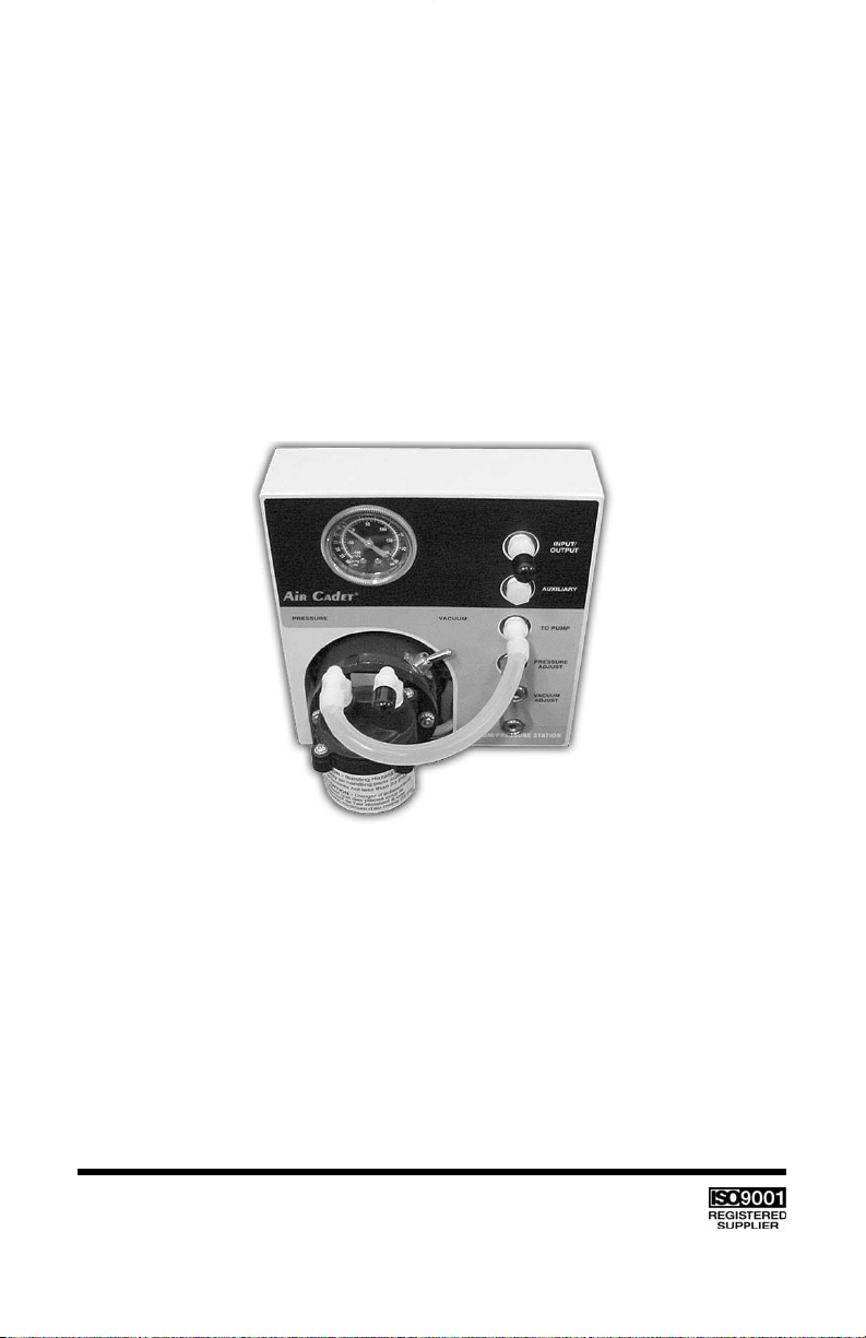
Operation (see Figure 3)
For pressure delivery, the manifold port marked “TO PUMP” should be
connected via the 9 inch long tube to the pump port marked “FOR PRESSURE,” with pressure regulated by the valve marked “PRESSURE
ADJUST.” The “INPUT/OUTPUT” port should be connected to suitable
containers for receiving pressurized air or gas. If a medium other than
ambient air is to be pressurized, the source of supply should be connected to the pump inlet port marked “FOR VACUUM.”
WARNING: Gas under pressure should not be used for supply as a haz-
ardous bursting condition could develop in the pump head.
Use only gases contained at atmospheric pressure.
CAUTION: Do not operate pump when pressure ports of both heads are
in a blocked condition.
To draw a regulated vacuum from a source, first, connect the source of
supply to the port marked “INPUT/OUTPUT” and then connect the “TO
PUMP” port to the pump inlet, marked “FOR VACUUM.” If the
Vacuum/Pressure Station was previously used for pressure delivery, be
sure all pressures are relieved before disconnecting tubing from the “FOR
PRESSURE” and/or the “INPUT/OUTPUT” port(s). This can be done best
by stopping the pump and gradually relieving pressure by turning the
“PRESSURE ADJUST” valve screw counterclockwise until the gauge
reads zero.
The motor is supplied with an internal thermal overload switch which may
trip if something happens to the pump. If this should occur, check the pump
to ensure that everything is normal. Allow motor to cool for approximately
30 minutes, then restart. If overload trips again, return the complete unit to
your dealer for repair. Refer to return policy in back of manual.
DANGER: Unplug power cord before any cleaning operation is started.
8

9
INPUT/
OUTPUT
AUXILIARY
TO PUMP
PRESSURE
ADJUST
VACUUM
ADJUST
FIGURE 3
PRESSURE
VACUUM
VACUUM PRESSURE STATION
When the pump is not in use, store in a clean, dry area. If ports on pump
are open, cover to keep dust and dirt from entering. Wipe power cord down
with dry towel and inspect for cracks in insulation after each use. Have
cord repaired, if found defective, prior to reusing.

10
SPECIFICATIONS
MODEL NO. 420-3901 420-3902
Power 100–115 +/- 10%, V AC, 60 Hz, 1.5A 230 +/- 10%, V AC, 50 Hz, 0.75A
Air Capacity (Vac.) 1050 Cu. Inch per min 900 Cu. Inch per min
Air Capacity (Press.) 900 Cu. Inch per min 750 Cu. Inch per min
Max. Pressure 18/21 psig* 18/21 psig*
Max. Suction 23 Inches Hg** 23 Inches Hg**
Housing Dimensions 9 in L x 8 in W x 8.75 in H 9 in L x 8 in W x 8.75 in H
Air capacity will depend on the application. Refer to Figure 1. It indicates the approximate flow with various input
and output conditions.
*Recommended Pressure: 18 psig Max.; continuous duty / 21 psig Max.; intermittent duty
**Recommended Vacuum: 23 in Hg continuous or intermittent

SPECIFICATIONS (CONT.)
Models 420-3901 and 420-3902
Operating Temperature Range: 0° to 40° C (32° to 104° F)
Humidity Range: 10% to 90% non-condensing
Altitude: Less than 2000 m
Pollution Degree: Pollution Degree 2
(Indoor usage - lab, office)
Enclosure Rating: IP 20 per IEC 60529
Weight: 4.1 kg (9 lbs)
Compliance: 230V (For CE Mark):
EN61010-1
(EU Low Voltage Directive) and
EN61326
( EU EMC Directive)
MAINTENANCE
DANGER: Unplug power cord before any cleaning operation is started.
For diaphragm replacement, disassemble top part of the Pump Head. Then
unscrew the diaphragm and install the new diaphragm. Reassemble the
Pump Head. It is good practice to replace the Pump Head when the
diaphragm is replaced. This ensures new, clean valves and maximum performance. Dirty valves will reduce performance.
Do not disassemble the pump housing from the motor. Proper assembly
(factory-adjusted) is critical for proper pump performance.
Keep the pump enclosure clean by using a mild detergent solution. Never
immerse nor use excessive fluid when cleaning the pump.
11

The regulation valves should be occasionally inspected for contamination
(frequency depends upon the application) by removing the adjustment
screw, spring and ball from each valve body—see Figure 4. Look for dirt or
grit around the venting holes in the adjustment screw and the valve body
and around the valve seating surfaces. These areas can easily be cleaned
with a cotton swab or clean cloth.
If vacuum cannot be regulated by adjusting the “VACUUM ADJUST” valve,
the valve’s O-ring has probably been damaged. Remove the adjustment
screw and replace the O-ring with a new one, Part No. B-1169-0011.
Always use caution when disassembling the regulation valves to avoid losing the valve ball and spring after the adjustment screw has been removed.
When reassembling, remember that in the “VACUUM ADJUST” valve, the
spring goes back in first, followed by the ball and the adjustment screw and
in the “PRESSURE ADJUST” valve, the ball must go in before the spring.
HELPFUL HINTS
1) If it is necessary to draw a vacuum or pressurize two lines simultaneously, the plastic pipe plug in the “AUXILIARY” port can be replaced by
any tube fitting with a standard 1/4 NPT male pipe thread on one end.
Be sure, however, to use a pipe thread sealant or tape on the male
thread to insure a leak-free fit.
2) The Station has been designed so the pump head can be serviced without removing the pump from the Station.
3) The easiest way to remove the silicone tubing from a barbed fitting is to
grasp the tubing around the fitting and twist it back and forth two or
three times. This releases the natural vacuum between the tube and the
fitting and minimizes stretching of the tubing.
4) The regulation valves can be adjusted with any narrow, flat instrument
such as a small coin or head of a key if a screwdriver is not available.
12
13

VALVE BODY
VALVE BODY
BALL
BALL
SPRING
SPRING
O-RING
O-RING
ADJUSTMENT SCREW
ADJUSTMENT SCREW
PRESSURE REGULATION VALVE
VACUUM REGULATION VALVE
FIGURE 4

REPLACEMENT PARTS LIST
Item Part No.
Vacuum regulation valve assembly B-2067-CR
Pressure regulation valve assembly B-2066-CR
Manifold Chamber Assy (with valves) D-1819
Vacuum/Pressure gauge B-2898
PUMP HEAD REPLACEMENT PARTS LIST
Item Part No.
Service Kit (Reinforced FLUOREL diaphragm only) 420-9004
Service Kit (Reinforced FLUOREL diaphragm, 420-9005
two retainers, two valves and plastic head)
Service Kit (Nitrile diaphragm, two retainers, 7530-06
two valves and plastic head)
Service Kit (FLUOREL diaphragm, two retainers, 7530-04
two valves and plastic head)
SPECIAL APPLICATIONS
Technical information and advice concerning the use of this product in specific applications may be obtained from our Engineering Department. If volume justifies, modifications can be made to adapt the unit to special customer applications. OEM inquiries are welcome and encouraged.
NOTE
The manufacturer reserves the right to make improvements in design,
construction and appearance of our products without notice.
14

15
WARRANTY
This product is warranted against defects in material or workmanship, and at the
option of the manufacturer or distributor, any defective product will be repaired or
replaced at no charge, or the purchase price will be refunded to the purchaser,
provided that: (a) the warranty claim is made in writing within the period of time
specified on this warranty card, (b) proof of purchase by bill of sale or receipted
invoice is submitted concurrently with the claim and shows that the product is
within the applicable warranty period, and (c) the purchaser complies with procedures for returns set forth in the general terms and conditions contained in the
manufacturer's or distributor's most recent catalog.
This warranty shall not apply to: (a) defects or damage resulting from: (i) misuse
of the product, (ii) use of the product in other than its normal and customary
manner, (iii) accident or neglect, (iv) improper testing, operation, maintenance,
service, repair, installation, or storage, (v) unauthorized alteration or modification,
or (b) post-expiration dated materials.
THIS WARRANTY IS THE EXCLUSIVE REMEDY OF THE PURCHASER, AND
THE MANUFACTURER AND DISTRIBUTOR DISCLAIM ALL OTHER
WARRANTIES, WHETHER EXPRESS, IMPLIED, OR STATUTORY, INCLUDING
WITHOUT LIMITATION, WARRANTIES OF MERCHANTABILITY AND FITNESS
FOR A PARTICULAR PURPOSE. NO EMPLOYEE, AGENT, OR REPRESENTATIVE OF THE MANUFACTURER OR DISTRIBUTOR IS AUTHORIZED TO BIND
THE MANUFACTURER OR DISTRIBUTOR TO ANY OTHER WARRANTY. IN NO
EVENT SHALL THE MANUFACTURER OR DISTRIBUTOR BE LIABLE FOR
INCIDENTAL, INDIRECT, SPECIAL OR CONSEQUENTIAL DAMAGES.
The warranty period for this product is two (2) years from date of purchase.
PRODUCT RETURN
To limit charges and delays, contact the seller or Manufacturer for authorization
and shipping instructions before returning the product, either within or outside of
the warranty period. When returning the product, please state the reason for the
return. For your protection, pack the product carefully and insure it against possible damage or loss. Any damages resulting from improper packaging are your
responsibility.
TECHNICAL ASSISTANCE
If you have any questions about the use of this product, contact the Manufacturer
or authorized seller.

16
Thermo Fisher Scientific
1-800-637-3739 (U.S. and Canada only)
11 (847) 381-7050 (Outside U.S.)
(847) 381-7050 (Local)
www.thermo.com
bar.barnant@thermofisher.com
Printed in U.S.A.
 Loading...